EP4006261A1 - Profil de plancher, ainsi qu'entretoise pour un profil de plancher à poser et procédé de pose d'un profil de plancher - Google Patents
Profil de plancher, ainsi qu'entretoise pour un profil de plancher à poser et procédé de pose d'un profil de plancher Download PDFInfo
- Publication number
- EP4006261A1 EP4006261A1 EP21209555.8A EP21209555A EP4006261A1 EP 4006261 A1 EP4006261 A1 EP 4006261A1 EP 21209555 A EP21209555 A EP 21209555A EP 4006261 A1 EP4006261 A1 EP 4006261A1
- Authority
- EP
- European Patent Office
- Prior art keywords
- floor
- profile
- profiles
- spacer
- tile
- Prior art date
- Legal status (The legal status is an assumption and is not a legal conclusion. Google has not performed a legal analysis and makes no representation as to the accuracy of the status listed.)
- Granted
Links
Images







Classifications
-
- E—FIXED CONSTRUCTIONS
- E04—BUILDING
- E04F—FINISHING WORK ON BUILDINGS, e.g. STAIRS, FLOORS
- E04F15/00—Flooring
- E04F15/02—Flooring or floor layers composed of a number of similar elements
- E04F15/02044—Separate elements for fastening to an underlayer
-
- E—FIXED CONSTRUCTIONS
- E04—BUILDING
- E04F—FINISHING WORK ON BUILDINGS, e.g. STAIRS, FLOORS
- E04F15/00—Flooring
- E04F15/02—Flooring or floor layers composed of a number of similar elements
- E04F15/02177—Floor elements for use at a specific location
- E04F15/02183—Floor elements for use at a specific location for outdoor use, e.g. in decks, patios, terraces, verandas or the like
-
- E—FIXED CONSTRUCTIONS
- E04—BUILDING
- E04F—FINISHING WORK ON BUILDINGS, e.g. STAIRS, FLOORS
- E04F15/00—Flooring
- E04F15/02—Flooring or floor layers composed of a number of similar elements
- E04F15/10—Flooring or floor layers composed of a number of similar elements of other materials, e.g. fibrous or chipped materials, organic plastics, magnesite tiles, hardboard, or with a top layer of other materials
- E04F15/102—Flooring or floor layers composed of a number of similar elements of other materials, e.g. fibrous or chipped materials, organic plastics, magnesite tiles, hardboard, or with a top layer of other materials of fibrous or chipped materials, e.g. bonded with synthetic resins
-
- E—FIXED CONSTRUCTIONS
- E04—BUILDING
- E04F—FINISHING WORK ON BUILDINGS, e.g. STAIRS, FLOORS
- E04F15/00—Flooring
- E04F15/02—Flooring or floor layers composed of a number of similar elements
- E04F15/02044—Separate elements for fastening to an underlayer
- E04F2015/0205—Separate elements for fastening to an underlayer with load-supporting elongated furring elements between the flooring elements and the underlayer
- E04F2015/02066—Separate elements for fastening to an underlayer with load-supporting elongated furring elements between the flooring elements and the underlayer with additional fastening elements between furring elements and flooring elements
- E04F2015/02077—Separate elements for fastening to an underlayer with load-supporting elongated furring elements between the flooring elements and the underlayer with additional fastening elements between furring elements and flooring elements the additional fastening elements located in-between two adjacent flooring elements
- E04F2015/02094—Engaging side grooves running along the whole length of the flooring elements
Definitions
- the invention relates to a floor profile, preferably to be laid outdoors, for forming a floor surface, in particular a terrace area, the floor profiles being produced as WPC profiles in an extrusion process and being fastened to a substructure formed by profile parts.
- the invention also relates to a spacer for floor profiles, which are preferably to be laid outdoors, for forming a floor area, in particular a terrace area, the floor profiles being produced as WPC profiles in an extrusion process and being fastened to a substructure formed by profile parts, the profile parts being in a laying state are arranged with a circumferential, joint-like distance from one another.
- the invention relates to a spacer for floor profiles, which are preferably to be laid outdoors, for forming a floor surface, in particular a terrace surface.
- the invention also relates to a method for laying floor profiles outdoors, for forming a floor area, in particular a terrace area, the floor profiles being produced as WPC profiles in an extrusion process and being fastened to a substructure formed by profile parts.
- Floor profiles of the type in question are known from practice, for example for forming a balcony or terrace floor.
- the floor profiles are preferably produced using the extrusion process, more preferably as profiles made from wood-plastic composites.
- the invention is concerned with the task of specifying a soil profile that is easy to handle.
- the invention is also concerned with the task of designing a spacer of the type in question in an improved manner.
- the elongated, rectangular or square floor profiles are formed according to tile profiles, with a length that is significantly smaller than an extension of the floor area formed in the direction of length and that the floor profiles are corresponding laid in a pattern known as a tile pattern.
- a tile-like laying pattern can be achieved by means of a variety of such floor profiles, with a possible length of a floor profile, which length exceeds the width of the same floor profile viewed transversely thereto, such a floor profile can be laid, for example, both in a direction of extension of the profile parts of the substructure and, as more preferably, transversely thereto.
- the ratio of the length of a soil profile to the width of the same soil profile viewed transversely to it can correspond, for example, to about 5:1 up to about 1:1, further for example, as is also preferred, about 3:1 or about 2:1
- the task can be solved first and foremost in that the spacer is supported on the profile parts.
- the result is preferably a quasi-floating arrangement of the spacer between the profile parts to be kept at a distance.
- the spacer there is preferably no direct contact with the substructure, for example in the form of a fastening or the like. Rather, as a result of this configuration, the spacer is suitable for moving within the floor area resulting from the floor profiles, for example in the event of any thermal changes in length.
- the spacer is preferably only supported on two or more profile parts, the latter optionally for example in a corner region in which more than two profile parts meet.
- the object can also be achieved with a spacer in that the spacer has one or more spring arms for elastically yielding contact with a floor profile, that the spacer has a gripping area for gripping under the floor profile and an engagement part for engaging in a groove of the floor profile, and that the undergripping area protrudes further than the engagement part in a deflection direction of the spring arm.
- the floor profiles can be arranged in the installation state with a circumferential, joint-like distance from one another.
- This gap-like distance between two floor or Tile profiles are formed the same all the way around when they are in an ideal laying condition.
- the distance in the region of a joint can correspond to approximately one fiftieth to approximately one two hundredth, further approximately one hundredth of the covering width viewed transversely to the longitudinal extension of the floor profiles.
- the covering width results preferably from the addition of the tile profile width and the dimension of the distance on one side of the tile profile to an immediately adjacent tile profile. Accordingly, with an exemplary cover width of about 350 to 450 mm, further for example 400 mm, there can be a distance of about 3.5 to 4.5 mm, further for example 4 mm, with a corresponding floor profile width of about 346.5 to 445 .5 mm, more for example 396 mm.
- the smallest distance between the soil profiles that is visible to the observer is essentially decisive, i.e. H.
- the above-described distance can also be designed to be continuous in a vertical direction over an entire thickness of the floor profile, aligned on a vertical plane. In a further preferred embodiment, this can result in an at least approximately constant distance over the above-described entire thickness of the floor profile. In this way, in particular, starting from the minimum visible distance described above Floor profiles to each other over the entire thickness of the floor profile, the distance may vary in a range of about 5 to 10%, viewed over the entire thickness of the floor profile, starting from an ideal installation state of the floor profiles, at least the visible distance is maintained.
- Floor profiles designed and laid in this way can be provided with a spacer which is only supported on the floor profiles.
- the result is preferably a quasi-floating arrangement of the spacer between the floor profiles.
- the preferably continuous distance can also preferably be provided essentially completely over the entire circumference of a soil profile. This at least as far as it is a floor profile that does not also form an edge of the floor surface at the same time.
- the distance can also be interrupted over the circumference by one or more spacers.
- the floor profiles can shift, for example due to thermal changes in length or also due to external mechanical influences on the substructure or on the profile parts forming the substructure. This can lead to some distances increasing and others decreasing, possibly even to the extent that the actually resulting joints may partially close. This can lead to an inconsistent joint pattern within the floor area, and also to injuries, for example in the case of children, and too large distances. This deficiency is counteracted by arranging the spacers described above.
- the spacer can also have one or more spring arms for elastically yielding contact with a floor profile. This can favorably result in an adjustment of the joint spacing, for example in the event of a thermal change in the length of the floor profiles. Due to the elastically restorable, correspondingly springy design of the spring arms, the joint pattern can be made more uniform overall, for example when the floor profiles lengthen as a result of temperature.
- the elastically resilient design of the spring arms can, as is also preferred, result from the design of the spring arm and also preferably from the selected material.
- the spring arm or arms can, as is also preferred, be formed in one piece and of the same material as the spacer overall, for example using a plastic injection molding process.
- the spacer can have a gripping area for gripping underneath the floor profile and an engagement part for engaging in the groove of the floor profile.
- the lower grip area can be designed, for example, in the form of a plate, more preferably for contact with the lower surface facing away from the visible surface of the soil profile.
- the engagement part can preferably extend at a distance above the undergrip area, so that a section of the tile profile can be enclosed in an approximately U-shaped cross-section between the engagement part that engages in the groove and the undergrip area.
- the spacer can form two mutually perpendicular ribs, which at the same time determine the distance between two mutually perpendicular separating surfaces of three soil profiles.
- the ribs of the spacer can be suitable for determining the distance between a longitudinally running joint, optionally continuous in the floor area, between essentially parallel floor profiles and a transverse joint between two longitudinally consecutive floor profiles.
- a substantially T-arrangement of the above-described joints can result in this area, the distances between which are defined by the corresponding positioning and design of the ribs of the spacer, at least with regard to a predetermined minimum dimension.
- the ribs of the spacer which run essentially perpendicularly to one another, can specify the same or also different minimum spacing dimensions.
- the ribs can run in a T-shape relative to one another, with a T-leg and a T-beam running transversely thereto.
- the T-beam can, as also preferred, serve to space two floor profiles running in the longitudinal direction and parallel to one another, while the T-leg preferably defines the spacing of two floor profiles following one another in the longitudinal direction in the region of the resulting transverse joint.
- the T-beam can be designed for elastically yielding contact with a floor profile. This can also result in an adjustment of the distance with further contact of the T-bar on the floor profile facing it, for example in the event of a thermal change in length of the floor profile.
- the T-beam or a differently designed section of the spacer which is designed to be elastically yielding, can yield elastically at a preferred and fundamentally assumed distance of, for example, 4 mm between the floor profiles such that with further contact of the T bar, a reduction in the distance by, for example, up to 50% or more, for example up to 60% or more, of the target distance of, for example, 4 mm can be achieved, so further, for example, a reduction in the distance to about 3 mm. Due to the elastically resilient, correspondingly resilient design of the T-beam or sections thereof, a reset of the distance to the desired nominal dimension is made possible, for example, in the event of a subsequent reduction in the width of the soil profile.
- the T-bar can be formed with one or more spring arms running at an angle to the extension of the T-bar.
- the spring arm or arms can, as is also preferred, be formed in one piece and of the same material with the T-beam and, via this, with the spacer as a whole, further for example in the plastic injection molding process.
- One or more lower grip areas can also be formed on the T-beam and/or on the T-leg.
- the engagement part can, as also preferred, be designed for engagement in the groove of the floor profile. Accordingly, the spacer can be held in a floating manner on the floor profile or profiles solely as a result of the engagement of the engagement part in the groove and the gripping under of the lower gripping arms.
- a lower gripping area is designed as a lower gripping arm with a length that can correspond to a multiple of the width of a lower gripping arm viewed transversely thereto.
- a second or a further lower gripping arm can extend, so that if necessary there is support on the underside on all the floor profiles kept at a distance from one another by the spacer.
- two lower gripping arms can be provided on both sides and running parallel to the T-leg, while a third lower gripping arm extending counter to these lower gripping arms can optionally be formed as an extension of the T-leg.
- the floor profiles can be fastened to the substructure formed by profile parts by means of a fixing part.
- a type of floating attachment can also result, as is preferred, which allows the floor profiles to be displaced relative to the profile parts, in particular in the longitudinal alignment of the profile parts, for example if the length of the floor profiles is thermally induced.
- a profile part of the substructure can also have a holding groove serving to hold the fixing part.
- Such a fixing part is, for example, from DE 20 2007 002 282 U1 known.
- This is preferably designed with engagement elements which are designed to engage in the same groove of the floor profile in which the engagement part of the spacer can also engage.
- the content of this utility model specification is hereby included in its entirety in the disclosure of the present invention, also for the purpose of including features of this utility model application in claims of the present invention.
- the floor profiles mounted in the edge area of the floor area can, for example, by mechanical action from the outside, further, for example, when movements in the longitudinal and/or width direction of the floor profile are stopped, without further measures be shifted outwards in the direction of the possibly open edge of the bottom surface, since correspondingly at the end (edge) no further support is provided, for example via a spacer.
- a fixing part is provided for the floor profile, which is held on the profile part of the substructure.
- the mounting of the fixing part on the substructure can, as is also preferred, be of the same or similar design as that of the fixing part.
- the fixing part prevents the undesired movement of the floor profile, for example in the event of external mechanical influences, but on the other hand allows the necessary movement, for example due to moisture-related length growth of the floor profile.
- the fixing part can more preferably be an aluminum part, for example an aluminum extruded part.
- the fixing part can be arranged adjacent to the fixing part in alignment of the profile part of the substructure. Fixing part and fixing part are preferably not connected. However, at least in a first installation position, there can be a partial vertical overlap of sections of the fixing part and the fixing part.
- fixing parts are provided on both sides adjacent to the fixing part, for interaction with the floor profiles connected to the substructure via the associated fixing part.
- the fixing part can have a profiling that brings about or increases the frictional connection between the fixing part and the floor profile.
- tooth-shaped elevations pointing in the direction of the underside of the soil profile can be formed, via which a mechanical anchoring in the area of the soil profile underside can be achieved in particular with a corresponding mechanical load on the soil profile.
- the profile parts of the substructure can extend transversely to a longitudinal direction of the floor profile.
- an extension of the profile parts directed longitudinally to the longitudinal extension of the floor profiles is also possible.
- the floor area formed in the laying state, can be formed, for example, by floor profiles which, with their longitudinal extent, extend both in Longitudinally the profile parts of the substructure as well as can be laid transversely thereto.
- floor profiles that have a length to width ratio of about 5:1 or less, for example up to a ratio of about 1:1, further for example as well as preferred, about 3:1 or about 2:1.
- floor profiles can be laid in a tile pattern that have a length of about 300 to 1300 mm, more preferably about 400 to 1200 mm, with a more preferred width of Floor profiles of about 350 to 450 mm, more preferably about 400 to mm.
- ranges or value ranges or multiple ranges specified above and below also include all intermediate values with regard to the disclosure, in particular in steps of 1/10 of the respective dimension, ie possibly also dimensionless.
- the specification 350 to 450 mm also includes the disclosure of 350.1 to 450 mm, 350 to 449.9 mm, 350.1 to 449.9 mm etc. This disclosure can be used to delimit a specified range limit from below and/or above, alternatively or additionally serve to disclose one or more singular values from a respectively specified range.
- This is preferably a substructure 3 for supporting floor profiles 1 arranged in a common horizontal plane, which are preferably produced in the extrusion process as so-called WPC profiles.
- WPC profiles preferably produced in the extrusion process as so-called WPC profiles.
- it can also be a two-layer, coextruded material or a hollow profile.
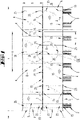
- the floor profiles 1 are formed with an elongated, rectangular plan, so that in the laying state, as shown in figure 1 is shown, for example, a tile-like pattern of the floor profiles 1 can be achieved.
- the floor profiles 1 are designed as tile profiles 4 .
- Such a tile profile 4 has a length a that is significantly smaller than an extension c of the floor surface 5 formed in the longitudinal direction of the tile profiles 4.
- the length a of a floor or Tile profile 1, 4, for example, correspond to a third or less, further, for example, a fifth or less to a tenth or less of the extension c.
- this above-described length a of a tile profile 4 corresponds to approximately two to three times the width b of the same tile profile 4 viewed transversely to the length a.
- a tile profile 4 with a length-width ratio of preferably 2:1 can have a length a of about 800 mm.
- the tile profiles 4 of a profile row 6 preferably have the same widths b, so that viewed in the longitudinal extension of such a profile row 6, there is a gap-like distance d that essentially runs continuously over the entire extension c in the area of a longitudinal gap 7 that forms as a result.
- Such a joint-like spacing e also occurs in the area of a transverse joint 8 in the direction of extension c between two consecutive tile profiles 4.
- the distances d and e of the longitudinal joints 7 and the transverse joints 8 can, as is also preferred, be chosen to be the same or at least approximately the same, at least in a first installation state, further for example in each case about 3 to 5 mm, more preferably about 4 mm in particular in the range the visible surface 12 of the floor profiles 1 amount.
- the distances preferably result over the entire thickness t of the tile profile 4.
- two rows of profiles 6 adjacent to one another are arranged with an offset relative to one another with respect to their transverse grooves 8 .
- This can result in an offset f viewed in the direction of extension c between two adjacent transverse grooves 8 of adjacent profile rows 6 in this direction, which offset f can be approximately 0.5 times or less, for example one third of the length a of a tile profile 4 .
- each tile profile 4 is preferably provided along both longitudinal side edges 9 with continuous grooves 10 running in the longitudinal direction.
- the narrow side edges 11 running transversely to the longitudinal side edges 9 can be designed without grooves.
- the relevant end faces of the narrow side edges 11 preferably run perpendicularly to the tile profile surface 12 with respect to a cross section through such a tile profile 4.
- the grooves 10 are more preferably open outwards in the direction of the longitudinal side edge 9, with reference to a cross-sectional view, for example according to FIG figure 3 a groove cover 21 preferably runs at an acute angle ⁇ to a horizontal plane when laid, such that, starting from a groove base 22, the groove 10 extends outwards in the direction of the longitudinal side edge 9 and upwards in the direction of the surface 10 extended.
- the groove base 39 is preferably aligned essentially parallel to the surface 12.
- top and bottom webs 23, 24 on the top and bottom of the groove 10 in the area of the longitudinal side edge 9, whereby, according to a preferred embodiment, the top web 23 extends the bottom web 24 by an amount of 1 up to 5 mm, for example about 3 to 3.5 mm.
- the substructure 3 is essentially made up of a plurality of profile parts 2, preferably with the same cross-section.
- a profile part 2 can, as is also preferred, be designed as an aluminum extrusion, whereby the same profile parts 2 can be produced in different dimensions with regard to their longitudinal extent L let reach.
- a plurality of such profile parts 2 can be provided in a parallel alignment, spaced evenly apart from one another. Depending on the area to be created, profile parts 2 can also be provided in a different alignment to the parallel arrangement.
- the profile rows 6 of the tile profiles 4 formed preferably run transversely to the longitudinal extension L of the profile parts 2.
- the tile profiles 4 can be aligned with respect to their length a in the transverse direction to the direction of extension of the profile parts 2. Alternatively or also in combination with this, alignment of tile profiles 4 with their longitudinal extent in the longitudinal direction of the profile parts 2 is also possible.
- the profile part 2 can have a receiving pocket 14 in the area of a support cover 13, which is preferably provided continuously with respect to the longitudinal extension L and for preferably latching receiving of an in figure 18 Fixing part 15 shown in a perspective individual view is used.
- the fixing part 15 can be constructed in tiers. Below, based on the installation condition, for example according to figure 16 , a rear gripping plate 16 is formed, which is formed substantially with a rectangular base. The narrow sides of the rear gripping plate 16 can be rounded. Overall, the dimensions of the rear gripping plate 16 are selected such that after the rear gripping plate 16 has been inserted into the receiving pocket 14 of the profile part 12, rotating the fixing part 15 by preferably 90° results in a form fit preventing the fixing part 15 from being pulled off.
- a preferably circular base section 17 is followed by a plate part 18 at the top, which forms engagement sections 19 in the direction of extension of the narrow side of the rear gripping plate 16 . These protrude well beyond the longitudinal edge of the rear gripping plate 16 .
- Spring elements 20 preferably formed on extend in the transverse direction to the alignment of the engagement sections 19.
- the attachment of the tile profiles 4 on the substructure 3 formed by the profile parts 2 is achieved by the fixing parts 15.
- the spring elements 20 of the fixing parts 15 move in an elastically deflectable manner against the facing end faces of the bottom webs 24 of the tile profiles 4. Accordingly, the spring elements 20 also determine the distance with respect to the longitudinal joint 7
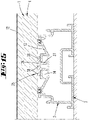
- Fixing part 15 attached tile profiles 4 resulting distance g can be a multiple of the cross-section according figure 16 correspond to the observed (visible) distance d above the groove 10 in the region of the top webs 23, for example approximately two to four times. This results in a deflection direction r of the spring elements 20 transverse to the joint (cf. figure 7 ).
- Spacers 25 are placed further between the rows of profiles 6 , preferably for evening out the distance d of the longitudinal joints 7 that is visible in the area of the surface 12 of the tile profiles 4 .
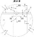
- the Figures 8 to 13 show the spacer 25 of the first embodiment in individual representations.
- This spacer 25 is used in particular when the floor profiles 1 are laid essentially in the same direction according to FIG figure 1 .
- the spacer 25 can also have a plate part 26 , similar to the fixing part 15 , which forms opposing plate-shaped engagement parts 27 for engagement in the facing tile profile groove 10 .
- Ribs 28 and 29 running towards one another in a T-shape are integrally formed on the underside of the plate part 26 , with the rib 29 forming a T-leg 30 being aligned essentially in the direction in which an engagement part 27 extends.
- the rib 28 forming a T-beam 31 running transversely to the T-leg 30 is formed on the plate part 26 approximately in the middle on the underside. Starting from this, the T-leg 30 or the rib 29 preferably extends up to a vertical overlap with the associated edge of the engagement part 27 (cf figure 11 ).
- these ribs 28 and 29 extend, starting from the underside of the plate part 26, over the thickness, viewed in the vertical direction, of the bottom web 24 delimiting the groove 10 at the bottom.
- grip areas 32, 33 are formed on the T-beam 31.
- the lower gripping areas 32, 33 are designed as lower gripping arms 32', 33', each with a length that can correspond to approximately 2 to 10 times the width viewed transversely thereto.
- These lower gripping arms 32, 33 extend towards the spacer 25 as shown in FIG figure 13 essentially preferably in the direction in which the T-leg 30 or the rib 29 extends.
- a lower gripping arm 32' is formed on the T-beam 31 essentially opposite the T-leg 30 or the rib 29, which extends over the facing edge of the engagement part with respect to its longitudinal extent and in the direction of deflection r of a spring arm 34 27 preferably protrudes.
- a projection dimension s can correspond approximately to the thickness of the lower gripping arm 32'.
- lower gripping arms 33′ can be formed on the T-beam 31, which lower gripping arms 33′ in turn preferably have a projection dimension s over the facing edge of the engagement part 27 can protrude.
- the dimensions of the lower gripping arms 32' and 33' are such that when the spacer 25 is in the assigned position, with the plate part 26 preferably resting on the groove base 22 of the tile profile groove 10, the respective lower gripping arm 32' or 33' grips the tile profile 4 in the area of its bottom web 24 engages below and thus enables sole support and retention of the spacer 25 on the tile profile 4 .
- the spacer 25 encloses the bottom web 24 quasi clamp-like, which clamp-like enclosing can be reached on both sides of the T-beam 31 .
- the rib 29 or the T-leg 30 engages in the transverse joint 8 between two tile profiles 4 arranged one behind the other in the direction of extension c. support.
- the thickness k of the rib 29 is preferably about 3 mm, for example, smaller than the usual distance e of, for example, about 4 mm between two profile ends. This contributes to the fact that a floor profile 1 can expand, for example due to the effect of temperature, without the neighboring floor profile 1 being displaced.
- the rib 29 or the T-leg 30, which is provided with a thickness k viewed transversely to the longitudinal extent, can thus also be designed to maintain a minimum distance e. This distance e can, as is also preferred, correspond approximately to the visible distance d between two profile rows 6 in the area of the ceiling webs 23 .
- the T-beam 31 (rib 28) reaching into the longitudinal joint 7 between two profile rows 6 in the arrangement position is further preferably designed for elastically yielding contact.
- the T-beam 31 can be provided with two spring arms 34 running at an angle in a V-shape. These spring arms 34 can, for example, be formed on the end of the longitudinal extension of the T-beam 31 on the latter and, starting therefrom, extend outwards and essentially in the direction of the lower gripping arm 32'.
- the spring arms 34 are part of the T-bar 31.
- the arrangement of the spacers 25 and the support via the spring arms 34 can compensate for the change in such a way that the entire floor surface 5 is preferably always considered set the same or at least approximately the same visible distances d, in particular with regard to the longitudinal joints 7 .
- a minimum distance specified at least by the thickness of the T-bar 31 is not fallen below.
- this minimum distance in the area of the bottom bars 24 is chosen so that, for example in the event of a thermal change in length, the longitudinal joint 7 is prevented from closing, particularly in the area of the ceiling webs 23 .
- fixing parts 35 can also be provided. These preferably serve to further secure the tile profiles 4 in a direction transverse to the longitudinal extent L of the profile parts 2 of the substructure 3.
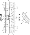
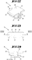
- FIG 17 shows such a fixing part 35 in a perspective individual representation.
- a plug-in projection 37 which is preferably U-shaped in a vertical cross section, extends downwards, via which the fixing part 35 is preferably inserted in the receiving pocket 14 of the profile part 2 can be plugged in.
- ribs 38 are formed on the upper side of the plate part 36 in the longitudinal extension of the fixing part 35 and thus in the longitudinal extension of the plug-in projection 37, which, with reference to a vertical cross section through the fixing part 35 as shown in FIG figure 15 can be formed approximately triangular with an upward pointing triangle tip. In the illustrated embodiment, three such ribs 38 are provided.
- each edge tile profile 4 is preferably assigned two such fixing parts 35 , which two fixing parts 35 of a tile profile 4 are more preferably plugged into the receiving pocket 14 of the same profile part 2 .
- fixing parts 35 can also be provided in the floor area 5, for example at a distance of 2 to 3 m from an edge of the floor area 5, with more preferably only one profile part per tile profile 4 2 is provided with such fixing parts 35.
- the relevant fixing parts 35 can be arranged on both sides of the fixing part 15 holding these tile profiles 4 (cf figures 4 and 16 ). With reference to a vertical projection, in this arrangement position the fixing parts 35 preferably reach under the area of the engagement sections 19 of the fixing part 15 (cf figure 16 ).
- the tile profiles 4 rest on the surface of the fixing part 35 that is formed with the ribs 38 .
- the profiling results in an increased frictional interaction and thus mechanical anchoring of the tile profile 4 and the fixing part 35, so that the tile profile 4 is prevented from shifting relative to the substructure 3.
- figure 20 1 shows an alternative laying arrangement of floor profiles 1, also designed here as tile profiles 4, with these tile profiles 4 also being able to have a length a which can correspond to approximately 2 to 3 times the width b viewed transversely thereto.
- tile profiles according to 4 figure 1 In contrast to the strictly serial arrangement of the tile profiles according to 4 figure 1 are in this laying arrangement different tile profiles 4, preferably in pairs, in the longitudinal extension L of the profile parts 2 and transversely thereto arranged. This can result in longitudinal joints 7 or transverse joints 8 that are essentially continuous, but also, as shown, longitudinal joints 7 or transverse joints 8 that are interrupted in their longitudinal extent by tile profiles 4 laid transversely.
- the spacers 25 that are preferably provided here are more preferably designed to be arranged between two side edges of the floor profiles 1 that run parallel to one another. In particular, all spacers 25 are aligned in the same way, such that the deflection direction r of the spring arms 34 , which are also provided here, points transversely to the longitudinal extension L of the profile parts 2 .
- two spacers 25 spaced apart from one another can be provided in the region of the narrow side edge 11, and in the case of a tile profile 4 oriented in the longitudinal extension L, four spacers, for example, can be provided along the longitudinal side edge 9 25
- this spacer 25 of the second embodiment has undergripping areas 32 and 33 spaced vertically downwards from the plate-shaped engagement parts 27 here too, which more preferably extend plate-shaped over the width of the spacer 25 viewed transversely to the avoidance direction r.
- the vertical spacing is also achieved in this embodiment by a rib 28 running in the direction of the width, on which rib protrudes on both sides beyond the engagement parts 27 and the gripping areas 32, 33 below Connect spring arms 34 according to the first embodiment described above.
- Floor profiles 1 which are characterized in that the floor profiles 1 are designed as elongated, rectangular or square tile profiles 4, with a length a that is significantly smaller than an extension of the designed floor area c, such that a tile-like pattern results in the laying state .
- a floor profile 1 which is characterized in that the floor profiles 1 are arranged in the laying state with a circumferential, joint-like distance d, e from one another.
- a floor profile which is characterized in that the distance d, e is continuous in a vertical direction over an entire thickness t of the floor profile 1, aligned on a vertical plane.
- a floor profile which is characterized in that the spacer 25 has one or more spring arms 34 for elastically yielding contact with a floor profile 1.
- a floor profile which is characterized in that the spacer 25 has a grip area 32, 33 for gripping the floor profile 1 below and an engagement part 27 for engaging in a groove 10 of the floor profile 1.
- a floor profile which is characterized in that the spacer 25 forms two mutually perpendicular ribs 28, 29, which at the same time determine the distance d, e between two mutually perpendicular separating surfaces of three floor profiles 1.
- a soil profile which is characterized in that the ribs 28, 29 run in a T-shape towards one another, with a T-leg 30 and a T-beam 31 running transversely thereto.
- a floor profile which is characterized in that the T-beam 31 is designed for elastically yielding contact with a floor profile 1.
- a soil profile which is characterized in that the T-bar 31 is formed with one or more spring arms 34 running at an angle to the extension of the T-bar 31 .
- a soil profile which is characterized in that one or more grip areas 32, 33 are formed on the T-beam 31 and/or on the T-leg 30.
- a floor profile which is characterized in that the engagement part 27 is designed to engage in the groove 10 of the floor profile 1 at a distance in the vertical direction from the undergripping areas 32, 33.
- a soil profile which is characterized in that a lower gripping area 32, 33 is designed as a lower gripping arm 32', 33'.
- a soil profile which is characterized in that a second or further lower gripping arm 33' can extend opposite to a first lower gripping arm 32'.
- a floor profile which is characterized in that the floor profiles 1 are fastened to the substructure 3 formed by profile parts 2 by means of a fixing part 15 .
- a floor profile which is characterized in that a fixing part 35 is provided for the floor profile 1, which is held on a profile part 2 of the substructure 3.
- a floor profile which is characterized in that the fixing part 35 is arranged adjacent to the fixing part 15 in the alignment of the profile part 2 of the substructure 3 .
- a floor profile which is characterized in that fixing parts 35 are provided adjacent to the fixing part 15 on both sides.
- a floor profile which is characterized in that the tile profile 4 interacts with the fixing part 35 in a non-positive manner.
- a floor profile which is characterized in that the profile parts 2 of the substructure 3 extend transversely to a longitudinal direction of the tile profiles 4 in the case of a rectangular design of a floor profile 1 .
- a spacer 25 which is characterized in that the spacer 25 is only supported on the floor profiles 1.
- a spacer 25 which is characterized in that the spacer 25 has one or more spring arms 34 for elastically yielding contact with a soil profile 1, that the spacer 25 has a gripping area 32, 33 for gripping underneath the soil profile 1 and an engagement part 27 for engaging in has a groove 10 of the floor profile 1, and that the gripping area 32, 33 projects further in a deflection direction r of the spring arm 34 than the engagement part 27.
- a method which is characterized in that the elongated, rectangular or square floor profiles 1 are formed in accordance with tile profiles 4, with a length a that is significantly smaller than an extension of the floor area formed c in the direction of length a and that the floor profiles 1 in accordance with a pattern known as a tile pattern.
- a method which is characterized in that in the course of laying a floor profile 1 an approximately equal distance d, e to all adjacent floor profiles 1 is formed all around.
- the invention also relates to designs in which some of the features mentioned in the above description are not implemented, in particular if they are clearly unnecessary for the respective application or can be replaced by other technically equivalent means.
- ⁇ b>List ⁇ /b> of reference numbers 1 soil profile 29 rib 2 profile part 30 T-shank 3 substructure 31 T bar 4 tile profile 32 lower reach 5 floor space 32' lower arm 6 profile series 33 lower reach 7 longitudinal joint 33' lower arm 8th transverse joint 34 spring arm 9 long margin 35 fixation part 10 groove 36 plate part 11 narrow margin 37 plug-in projection 12 surface 38 rib 13 carrier blanket 39 groove bottom 14 receiving bag 15 fixing part a length 16 rear grip plate b Broad 17 base section c extent 18 plate part i.e Distance 19 engagement section e Distance 20 spring element f offset dimension 21 groove cover G Distance 22 groove bottom k thickness 23 ceiling bar m thickness 24 bottom walkway right evasive direction 25 spacers s oversize 26 plate part t thickness 27 engaging part L longitudinal extent 28 rib a angle
Landscapes
- Engineering & Computer Science (AREA)
- Architecture (AREA)
- Civil Engineering (AREA)
- Structural Engineering (AREA)
- Floor Finish (AREA)
Priority Applications (1)
| Application Number | Priority Date | Filing Date | Title |
|---|---|---|---|
| DE102021130982.4A DE102021130982A1 (de) | 2020-11-25 | 2021-11-25 | Bodenprofil sowie Abstandshalter für ein zu verlegendes Bodenprofil und Verfahren zum Verlegen eines Bodenprofils |
Applications Claiming Priority (1)
| Application Number | Priority Date | Filing Date | Title |
|---|---|---|---|
| DE202020106783.4U DE202020106783U1 (de) | 2020-11-25 | 2020-11-25 | Bodenprofil sowie Abstandshalter für ein zu verlegendes Bodenprofil |
Publications (3)
| Publication Number | Publication Date |
|---|---|
| EP4006261A1 true EP4006261A1 (fr) | 2022-06-01 |
| EP4006261B1 EP4006261B1 (fr) | 2025-09-10 |
| EP4006261C0 EP4006261C0 (fr) | 2025-09-10 |
Family
ID=78725318
Family Applications (1)
| Application Number | Title | Priority Date | Filing Date |
|---|---|---|---|
| EP21209555.8A Active EP4006261B1 (fr) | 2020-11-25 | 2021-11-22 | Surface de sol, notamment surface de terrasse |
Country Status (2)
| Country | Link |
|---|---|
| EP (1) | EP4006261B1 (fr) |
| DE (2) | DE202020106783U1 (fr) |
Cited By (1)
| Publication number | Priority date | Publication date | Assignee | Title |
|---|---|---|---|---|
| AU2024205068B2 (en) * | 2023-07-26 | 2026-02-12 | Feeling Wood Ltd | Snap-In Member, Assembled Decking Combination And Method Of Assembling Decking |
Families Citing this family (1)
| Publication number | Priority date | Publication date | Assignee | Title |
|---|---|---|---|---|
| IT202200004895A1 (it) * | 2022-03-14 | 2022-06-14 | Pontarolo Eng S P A | Sistema per il fissaggio di doghe. |
Citations (4)
| Publication number | Priority date | Publication date | Assignee | Title |
|---|---|---|---|---|
| US20050193663A1 (en) * | 2003-01-30 | 2005-09-08 | David Lombardo | Structural interlocking exterior deck tile system |
| DE202007002282U1 (de) | 2007-02-16 | 2008-06-19 | Möller GmbH & Co. KG | Profilelemente |
| US20110203200A1 (en) * | 2009-10-30 | 2011-08-25 | Marquardt Robert H | Deck system |
| KR101378077B1 (ko) * | 2011-03-03 | 2014-03-27 | 김운정 | 목재 데크 연결용 클립 |
Family Cites Families (1)
| Publication number | Priority date | Publication date | Assignee | Title |
|---|---|---|---|---|
| JP3739255B2 (ja) * | 2000-07-18 | 2006-01-25 | 三洋工業株式会社 | 屋外床敷設工法及び屋外床敷設構造 |
-
2020
- 2020-11-25 DE DE202020106783.4U patent/DE202020106783U1/de active Active
-
2021
- 2021-11-22 EP EP21209555.8A patent/EP4006261B1/fr active Active
- 2021-11-25 DE DE102021130982.4A patent/DE102021130982A1/de active Pending
Patent Citations (4)
| Publication number | Priority date | Publication date | Assignee | Title |
|---|---|---|---|---|
| US20050193663A1 (en) * | 2003-01-30 | 2005-09-08 | David Lombardo | Structural interlocking exterior deck tile system |
| DE202007002282U1 (de) | 2007-02-16 | 2008-06-19 | Möller GmbH & Co. KG | Profilelemente |
| US20110203200A1 (en) * | 2009-10-30 | 2011-08-25 | Marquardt Robert H | Deck system |
| KR101378077B1 (ko) * | 2011-03-03 | 2014-03-27 | 김운정 | 목재 데크 연결용 클립 |
Cited By (1)
| Publication number | Priority date | Publication date | Assignee | Title |
|---|---|---|---|---|
| AU2024205068B2 (en) * | 2023-07-26 | 2026-02-12 | Feeling Wood Ltd | Snap-In Member, Assembled Decking Combination And Method Of Assembling Decking |
Also Published As
| Publication number | Publication date |
|---|---|
| DE102021130982A1 (de) | 2022-05-25 |
| EP4006261B1 (fr) | 2025-09-10 |
| EP4006261C0 (fr) | 2025-09-10 |
| DE202020106783U1 (de) | 2022-02-28 |
Similar Documents
| Publication | Publication Date | Title |
|---|---|---|
| DE20080141U1 (de) | Bauteile oder Anordnung mit derartigen Bauteilen und Klammer hierfür | |
| DE202007016585U1 (de) | Profilschienensystem | |
| DE2735901A1 (de) | Fassadenkonstruktion, bestehend aus plattenfoermigen, vorzugsweise keramischen bauelementen | |
| EP0443441B1 (fr) | Grillage | |
| EP2816172A2 (fr) | Système de montage pour un revêtement de sol | |
| EP4006261B1 (fr) | Surface de sol, notamment surface de terrasse | |
| DE3434069A1 (de) | Haltevorrichtung zur loesbaren fixierung von leisten- und/oder streifenfoermigen koerpern in, an, auf oder unter tragkonstruktionen | |
| DE3032359C2 (de) | Unterkonstruktion zur Befestigung einer Wandbekleidung | |
| AT1255U1 (de) | Fassade | |
| DE4239051C2 (de) | Gebäudewandverkleidung | |
| EP1394337B1 (fr) | Panneau | |
| DE2639552A1 (de) | Vorrichtung zur befestigung von hinterluefteten fassaden an gebaeudewaenden | |
| DE3641747C2 (de) | Fassadenplatten zur Befestigung an einem Lattengerüst sowie Halteklammer zum Festlegen derartiger Fassadenplatten an dem Lattengerüst | |
| DE4417970C2 (de) | Deckenelement und damit hergestellte Zwischendecke | |
| DE8617287U1 (de) | Verglasungsklotz | |
| EP0213451B1 (fr) | Rail pour une construction de support d'un bardage de mur ou plafond | |
| DE102020125702B4 (de) | Belag für den Außenbereich | |
| DE9420155U1 (de) | FAssadenbekleidung mit horizontalen Halteprofilen | |
| EP0045460B1 (fr) | Elément porteur en forme de barre profilée pour un support d'enduit | |
| DE102022115118A1 (de) | Tragprofilkonstruktion | |
| EP2901911A1 (fr) | Paillasson | |
| EP1069258A2 (fr) | Profilé de jointoiement | |
| DE29706055U1 (de) | Einrichtung zum Aufbringen von Putz- bzw. Mörtelschichten auf Wände sowie Bausatz und Blechkörper zu deren Herstellung | |
| DE1286282B (de) | Bausatz zum Verbinden von plattenfoermigen Bauelementen mit Baukonstruktionen | |
| DE102012025362A1 (de) | Firstprofilelement für ein Satteldach und Verfahren zum Montieren eines Satteldachs |
Legal Events
| Date | Code | Title | Description |
|---|---|---|---|
| PUAI | Public reference made under article 153(3) epc to a published international application that has entered the european phase |
Free format text: ORIGINAL CODE: 0009012 |
|
| STAA | Information on the status of an ep patent application or granted ep patent |
Free format text: STATUS: THE APPLICATION HAS BEEN PUBLISHED |
|
| AK | Designated contracting states |
Kind code of ref document: A1 Designated state(s): AL AT BE BG CH CY CZ DE DK EE ES FI FR GB GR HR HU IE IS IT LI LT LU LV MC MK MT NL NO PL PT RO RS SE SI SK SM TR |
|
| STAA | Information on the status of an ep patent application or granted ep patent |
Free format text: STATUS: REQUEST FOR EXAMINATION WAS MADE |
|
| 17P | Request for examination filed |
Effective date: 20221125 |
|
| RBV | Designated contracting states (corrected) |
Designated state(s): AL AT BE BG CH CY CZ DE DK EE ES FI FR GB GR HR HU IE IS IT LI LT LU LV MC MK MT NL NO PL PT RO RS SE SI SK SM TR |
|
| STAA | Information on the status of an ep patent application or granted ep patent |
Free format text: STATUS: EXAMINATION IS IN PROGRESS |
|
| 17Q | First examination report despatched |
Effective date: 20240513 |
|
| GRAP | Despatch of communication of intention to grant a patent |
Free format text: ORIGINAL CODE: EPIDOSNIGR1 |
|
| STAA | Information on the status of an ep patent application or granted ep patent |
Free format text: STATUS: GRANT OF PATENT IS INTENDED |
|
| INTG | Intention to grant announced |
Effective date: 20250515 |
|
| GRAS | Grant fee paid |
Free format text: ORIGINAL CODE: EPIDOSNIGR3 |
|
| GRAA | (expected) grant |
Free format text: ORIGINAL CODE: 0009210 |
|
| STAA | Information on the status of an ep patent application or granted ep patent |
Free format text: STATUS: THE PATENT HAS BEEN GRANTED |
|
| AK | Designated contracting states |
Kind code of ref document: B1 Designated state(s): AL AT BE BG CH CY CZ DE DK EE ES FI FR GB GR HR HU IE IS IT LI LT LU LV MC MK MT NL NO PL PT RO RS SE SI SK SM TR |
|
| REG | Reference to a national code |
Ref country code: GB Ref legal event code: FG4D Free format text: NOT ENGLISH |
|
| REG | Reference to a national code |
Ref country code: CH Ref legal event code: EP |
|
| REG | Reference to a national code |
Ref country code: IE Ref legal event code: FG4D Free format text: LANGUAGE OF EP DOCUMENT: GERMAN |
|
| U01 | Request for unitary effect filed |
Effective date: 20250910 |
|
| U07 | Unitary effect registered |
Designated state(s): AT BE BG DE DK EE FI FR IT LT LU LV MT NL PT RO SE SI Effective date: 20250915 |
|
| U20 | Renewal fee for the european patent with unitary effect paid |
Year of fee payment: 5 Effective date: 20251119 |
|
| PG25 | Lapsed in a contracting state [announced via postgrant information from national office to epo] |
Ref country code: NO Free format text: LAPSE BECAUSE OF FAILURE TO SUBMIT A TRANSLATION OF THE DESCRIPTION OR TO PAY THE FEE WITHIN THE PRESCRIBED TIME-LIMIT Effective date: 20251210 |
|
| PG25 | Lapsed in a contracting state [announced via postgrant information from national office to epo] |
Ref country code: HR Free format text: LAPSE BECAUSE OF FAILURE TO SUBMIT A TRANSLATION OF THE DESCRIPTION OR TO PAY THE FEE WITHIN THE PRESCRIBED TIME-LIMIT Effective date: 20250910 |
|
| PG25 | Lapsed in a contracting state [announced via postgrant information from national office to epo] |
Ref country code: GR Free format text: LAPSE BECAUSE OF FAILURE TO SUBMIT A TRANSLATION OF THE DESCRIPTION OR TO PAY THE FEE WITHIN THE PRESCRIBED TIME-LIMIT Effective date: 20251211 |
|
| PG25 | Lapsed in a contracting state [announced via postgrant information from national office to epo] |
Ref country code: PL Free format text: LAPSE BECAUSE OF FAILURE TO SUBMIT A TRANSLATION OF THE DESCRIPTION OR TO PAY THE FEE WITHIN THE PRESCRIBED TIME-LIMIT Effective date: 20250910 |
|
| PG25 | Lapsed in a contracting state [announced via postgrant information from national office to epo] |
Ref country code: RS Free format text: LAPSE BECAUSE OF FAILURE TO SUBMIT A TRANSLATION OF THE DESCRIPTION OR TO PAY THE FEE WITHIN THE PRESCRIBED TIME-LIMIT Effective date: 20251210 |
|
| PG25 | Lapsed in a contracting state [announced via postgrant information from national office to epo] |
Ref country code: ES Free format text: LAPSE BECAUSE OF FAILURE TO SUBMIT A TRANSLATION OF THE DESCRIPTION OR TO PAY THE FEE WITHIN THE PRESCRIBED TIME-LIMIT Effective date: 20250910 |
|
| PG25 | Lapsed in a contracting state [announced via postgrant information from national office to epo] |
Ref country code: SM Free format text: LAPSE BECAUSE OF FAILURE TO SUBMIT A TRANSLATION OF THE DESCRIPTION OR TO PAY THE FEE WITHIN THE PRESCRIBED TIME-LIMIT Effective date: 20250910 |
|
| PG25 | Lapsed in a contracting state [announced via postgrant information from national office to epo] |
Ref country code: IS Free format text: LAPSE BECAUSE OF FAILURE TO SUBMIT A TRANSLATION OF THE DESCRIPTION OR TO PAY THE FEE WITHIN THE PRESCRIBED TIME-LIMIT Effective date: 20260110 |
|
| PG25 | Lapsed in a contracting state [announced via postgrant information from national office to epo] |
Ref country code: CZ Free format text: LAPSE BECAUSE OF FAILURE TO SUBMIT A TRANSLATION OF THE DESCRIPTION OR TO PAY THE FEE WITHIN THE PRESCRIBED TIME-LIMIT Effective date: 20250910 |
|
| PG25 | Lapsed in a contracting state [announced via postgrant information from national office to epo] |
Ref country code: SK Free format text: LAPSE BECAUSE OF FAILURE TO SUBMIT A TRANSLATION OF THE DESCRIPTION OR TO PAY THE FEE WITHIN THE PRESCRIBED TIME-LIMIT Effective date: 20250910 |