EP4006265B1 - Anker für eine selbstkletternde struktur - Google Patents
Anker für eine selbstkletternde struktur Download PDFInfo
- Publication number
- EP4006265B1 EP4006265B1 EP20847135.9A EP20847135A EP4006265B1 EP 4006265 B1 EP4006265 B1 EP 4006265B1 EP 20847135 A EP20847135 A EP 20847135A EP 4006265 B1 EP4006265 B1 EP 4006265B1
- Authority
- EP
- European Patent Office
- Prior art keywords
- vertical
- self
- metal inserts
- interlocking
- spikes
- Prior art date
- Legal status (The legal status is an assumption and is not a legal conclusion. Google has not performed a legal analysis and makes no representation as to the accuracy of the status listed.)
- Active
Links
Images




Classifications
-
- B—PERFORMING OPERATIONS; TRANSPORTING
- B66—HOISTING; LIFTING; HAULING
- B66C—CRANES; LOAD-ENGAGING ELEMENTS OR DEVICES FOR CRANES, CAPSTANS, WINCHES, OR TACKLES
- B66C23/00—Cranes comprising essentially a beam, boom, or triangular structure acting as a cantilever and mounted for translatory of swinging movements in vertical or horizontal planes or a combination of such movements, e.g. jib-cranes, derricks, tower cranes
- B66C23/18—Cranes comprising essentially a beam, boom, or triangular structure acting as a cantilever and mounted for translatory of swinging movements in vertical or horizontal planes or a combination of such movements, e.g. jib-cranes, derricks, tower cranes specially adapted for use in particular purposes
- B66C23/20—Cranes comprising essentially a beam, boom, or triangular structure acting as a cantilever and mounted for translatory of swinging movements in vertical or horizontal planes or a combination of such movements, e.g. jib-cranes, derricks, tower cranes specially adapted for use in particular purposes with supporting couples provided by walls of buildings or like structures
- B66C23/208—Cranes comprising essentially a beam, boom, or triangular structure acting as a cantilever and mounted for translatory of swinging movements in vertical or horizontal planes or a combination of such movements, e.g. jib-cranes, derricks, tower cranes specially adapted for use in particular purposes with supporting couples provided by walls of buildings or like structures with supporting couples provided from the side, e.g. by walls of buildings
-
- B—PERFORMING OPERATIONS; TRANSPORTING
- B66—HOISTING; LIFTING; HAULING
- B66C—CRANES; LOAD-ENGAGING ELEMENTS OR DEVICES FOR CRANES, CAPSTANS, WINCHES, OR TACKLES
- B66C23/00—Cranes comprising essentially a beam, boom, or triangular structure acting as a cantilever and mounted for translatory of swinging movements in vertical or horizontal planes or a combination of such movements, e.g. jib-cranes, derricks, tower cranes
- B66C23/18—Cranes comprising essentially a beam, boom, or triangular structure acting as a cantilever and mounted for translatory of swinging movements in vertical or horizontal planes or a combination of such movements, e.g. jib-cranes, derricks, tower cranes specially adapted for use in particular purposes
- B66C23/20—Cranes comprising essentially a beam, boom, or triangular structure acting as a cantilever and mounted for translatory of swinging movements in vertical or horizontal planes or a combination of such movements, e.g. jib-cranes, derricks, tower cranes specially adapted for use in particular purposes with supporting couples provided by walls of buildings or like structures
- B66C23/24—Mobile wall cranes
-
- B—PERFORMING OPERATIONS; TRANSPORTING
- B66—HOISTING; LIFTING; HAULING
- B66C—CRANES; LOAD-ENGAGING ELEMENTS OR DEVICES FOR CRANES, CAPSTANS, WINCHES, OR TACKLES
- B66C23/00—Cranes comprising essentially a beam, boom, or triangular structure acting as a cantilever and mounted for translatory of swinging movements in vertical or horizontal planes or a combination of such movements, e.g. jib-cranes, derricks, tower cranes
- B66C23/18—Cranes comprising essentially a beam, boom, or triangular structure acting as a cantilever and mounted for translatory of swinging movements in vertical or horizontal planes or a combination of such movements, e.g. jib-cranes, derricks, tower cranes specially adapted for use in particular purposes
- B66C23/26—Cranes comprising essentially a beam, boom, or triangular structure acting as a cantilever and mounted for translatory of swinging movements in vertical or horizontal planes or a combination of such movements, e.g. jib-cranes, derricks, tower cranes specially adapted for use in particular purposes for use on building sites; constructed, e.g. with separable parts, to facilitate rapid assembly or dismantling, for operation at successively higher levels, for transport by road or rail
- B66C23/28—Cranes comprising essentially a beam, boom, or triangular structure acting as a cantilever and mounted for translatory of swinging movements in vertical or horizontal planes or a combination of such movements, e.g. jib-cranes, derricks, tower cranes specially adapted for use in particular purposes for use on building sites; constructed, e.g. with separable parts, to facilitate rapid assembly or dismantling, for operation at successively higher levels, for transport by road or rail constructed to operate at successively higher levels
- B66C23/32—Self-hoisting cranes
-
- E—FIXED CONSTRUCTIONS
- E04—BUILDING
- E04G—SCAFFOLDING; FORMS; SHUTTERING; BUILDING IMPLEMENTS OR AIDS, OR THEIR USE; HANDLING BUILDING MATERIALS ON THE SITE; REPAIRING, BREAKING-UP OR OTHER WORK ON EXISTING BUILDINGS
- E04G3/00—Scaffolds essentially supported by building constructions, e.g. adjustable in height
- E04G3/28—Mobile scaffolds; Scaffolds with mobile platforms
-
- E—FIXED CONSTRUCTIONS
- E04—BUILDING
- E04G—SCAFFOLDING; FORMS; SHUTTERING; BUILDING IMPLEMENTS OR AIDS, OR THEIR USE; HANDLING BUILDING MATERIALS ON THE SITE; REPAIRING, BREAKING-UP OR OTHER WORK ON EXISTING BUILDINGS
- E04G5/00—Component parts or accessories for scaffolds
- E04G5/04—Means for fastening, supporting, or bracing scaffolds on or against building constructions
- E04G5/046—Means for fastening, supporting, or bracing scaffolds on or against building constructions for fastening scaffoldings on walls
-
- E—FIXED CONSTRUCTIONS
- E04—BUILDING
- E04G—SCAFFOLDING; FORMS; SHUTTERING; BUILDING IMPLEMENTS OR AIDS, OR THEIR USE; HANDLING BUILDING MATERIALS ON THE SITE; REPAIRING, BREAKING-UP OR OTHER WORK ON EXISTING BUILDINGS
- E04G11/00—Forms, shutterings, or falsework for making walls, floors, ceilings, or roofs
- E04G11/06—Forms, shutterings, or falsework for making walls, floors, ceilings, or roofs for walls, e.g. curved end panels for wall shutterings; filler elements for wall shutterings; shutterings for vertical ducts
- E04G11/20—Movable forms; Movable forms for moulding cylindrical, conical or hyperbolical structures; Templates serving as forms for positioning blocks or the like
- E04G11/28—Climbing forms, i.e. forms which are not in contact with the poured concrete during lifting from layer to layer and which are anchored in the hardened concrete
-
- E—FIXED CONSTRUCTIONS
- E04—BUILDING
- E04G—SCAFFOLDING; FORMS; SHUTTERING; BUILDING IMPLEMENTS OR AIDS, OR THEIR USE; HANDLING BUILDING MATERIALS ON THE SITE; REPAIRING, BREAKING-UP OR OTHER WORK ON EXISTING BUILDINGS
- E04G3/00—Scaffolds essentially supported by building constructions, e.g. adjustable in height
- E04G3/28—Mobile scaffolds; Scaffolds with mobile platforms
- E04G2003/286—Mobile scaffolds; Scaffolds with mobile platforms mobile vertically
Definitions
- This description relates, as its title indicates, to an anchor for the type of self-climbing structure used on vertical and near-vertical concrete surfaces, for example in the assembly and maintenance of totally or partially precast concrete towers, the self-climbing structure being able to be used for the support of cranes, platforms, and other auxiliary elements.
- the anchor uses metal inserts in the precast concrete tower and interlocking spikes in the self-climbing structure that are provided with rotary and rocking movement.
- the invention refers to the field of self-climbing structures used by vertical and near-vertical concrete surfaces.
- GB2363817 (A ) discloses a modular building element such as a brick or block comprising an anchor means such as a hook, a ring, or a channel to permit the attachment of an object, e.g. a safety net.
- the bricks bearing rings are built into the wall of a building along with conventional bricks, and are used to support a safety net to protect workers during construction. After construction, the anchors may be removed and the wall plastered in conventional manner.
- CN107512668 (A ) discloses a climbing device, in particular a self-locking type wall attachment climbing device, and discloses a gravity self-locking type wall attachment climbing device.
- the gravity self-locking type wall attachment climbing device comprises a bottom climbing counter-force steel frame, an upper climbing structure steel frame, a large-stroke counter-force jack, wall attachment embedded parts, wall attachment climbing rails, gravity self-locking pin shafts and steel claws.
- WO2017055598 discloses a hoisting system for the installation of a wind turbine wherein said hoisting system comprises measures to achieve a load bearing connection to the tower of the wind turbine and comprises measures to move the hoisting system up and down along the tower wherein the hoisting system, when it is fixed to an already installed part of the wind turbine tower with said load bearing connection, is arranged to install or remove any of a tower segment, a nacelle, a generator, a hub, and a blade in one or more combined hoists or in a single hoist.
- This type of anchor that is used presents the problem of requiring great precision, both in positioning the anchor elements in the tower modules, and aligning the lateral locking elements for their actuation, which in the event of any slight deviations in measurements, any dirt or dilatations in materials, or misalignments, may lead to coupling failures which prevent the correct operation of the self-supporting structure, and which may be impossible to resolve or offset.
- the anchoring of the crane in the concrete tower is delicate as concrete does not withstand tensile or shear loads well, so that, in order not to weaken the tower, the effect of the connection of the crane on the segment must be minimal, which is not the case in these embodiments.
- the interlocking spikes are inserted into various metal inserts in such a way that the lower part of each main body of the interlocking spike is in contact with the inner part of the hollow body of its corresponding metal insert, transmitting the weight of the self-climbing structure to the tower and maintaining its position due to that weight, while the end plates fit against the peripheral end surfaces of the metal inserts, blocking any horizontal displacement of the interlocking spikes, and thus preventing them from coming loose.
- the interlocking spikes are fixed, if in pairs, on both ends of a central arm, provided with free rotation movement, by means of a shaft, with respect to the main support of the assembly.
- the interlocking spikes are provided with multiple chamfers, both on the main body and on the end plates.
- This anchor for self-climbing structure provides multiple advantages over the equipment currently available, the most important being that as it uses appropriately-sized, round metal inserts, the tensile and shear loads on the concrete of the vertical and near-vertical concrete surface are minimised.
- Another notable advantage is that in order to ensure the even, centred distribution of loads, a spherical support has been used, which has the same radius at the point of support and on the support, guaranteeing maximum contact and optimal load distribution.
- rocking system of the central arm enables alignment errors between the crane and the vertical or near-vertical concrete surface, or between tower anchors (or concrete surface) and the crane climbing frames to be absorbed to a certain extent.
- the tilting of the spherical supports together with the tilting of the central support arm of the "spikes" provides support even when they are off-centre and facilitates the self-correction of any possible coupling position and alignment errors.
- the very design of the spikes also favours their entry and centring in vertical and near-vertical concrete surfaces. To this end, they have a series of lead chamfers to guide their entry and, following this effect, the free rotations of the spherical support on the central shaft and of the central arm facilitate entry and correct support of the spikes in the metal inserts.
- Another advantage of this invention is that since there is a spherical support on the interlockings that can absorb manufacturing and alignment errors and transfer the support loads in the central zone of the segment of the vertical and near-vertical concrete surface, load transmission to the segment is mainly compression which is that best withstood by concrete.
- the support on the vertical and near-vertical concrete surface is by simply adding metal inserts that are welded, secured with wire or another means to the internal reinforcement of the segment, so that lateral loads are transferred to the concrete through the concrete reinforcement, and they are, in their simplest solution, turned parts that can be fixed to the mould when the segment is concreted during its manufacturing process, with practically no variation or increase in cost.
- Another additional advantage is that, in the alternative embodiment in a buttonhole shape, greater alignment errors are able to be absorbed, so that there are greater entry tolerances at the top part of these, this way providing an even better guarantee that the interlocking spikes enter the tower and then, upon descending, support and centre in the same way as if they were totally round in shape.
- any self-climbing structure that supports any device or machine, such as, for example, a crane or a work platform, and that it is applicable and usable both on flat or curved, vertical and near-vertical surfaces with a free form and variable incline, with progressions or individual movements of variable length, adapted to the structure or zone to be climbed.
- FIG. 1 a system is illustrated, of the type used on vertical and near-vertical concrete surfaces, for example in the assembly and maintenance of precast concrete towers (1), the self-climbing structure (2) being able to be used for the support of cranes (3), platforms, and other auxiliary elements.
- the self-climbing structure (2) being able to be used for the support of cranes (3), platforms, and other auxiliary elements.
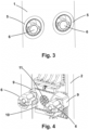
- the openings in the wall can be through-hole openings, and in this case the metal inserts (5), as shown in figures 7a and 7b are shaped as a hollow body (15) finished at both its ends by two peripheral end surfaces (16) of a larger size, defining a common through-hole opening.
- the wall openings are not through-holes and adopt the form of a hollow or niche. In both cases they can adopt a circular shape, as shown in figure 10a or alternatively as shown in figure 10b , a buttonhole shape, in which the top part is wider than the lower part, the lower part being semi-circular in shape.
- the interlocking spikes (6) comprise, as is shown in figures 8a, 8b and 8c ,
- the interlocking spikes (6) are inserted in some of the metal inserts (5), in such a way that the lower part of each main body (12) of the interlocking spike (6) is in contact with the inner part of the hollow body (15) of its corresponding metal insert (5), while the end plates (14) remain fitted against the peripheral end surfaces (16) of the metal inserts (5).
- the interlocking spikes (6) are distributed in pairs, at the same height, on each frame (4a, 4b and 4c), the metal inserts (5) being distributed vertically aligned in groups of two at the same height, at each height established for coupling on the vertical or near-vertical concrete surface (1).
- the interlocking spikes (6) are distributed as one per frame (4a, 4b and 4c), the metal inserts (5) being distributed vertically aligned, as one at each height established for coupling on the vertical or near-vertical concrete surface (1). It is technically possible to carry out other variants with groups of three or more interlocking spikes (6) on each frame and, correspondingly, with groups of three or more metal inserts (5) at each height.
- two of the frames (4b and 4c) are self-motorised and movable along the self-climbing structure (2) and at least one of them is a frame (4a) fixed to the self-climbing structure (2).
- An alternative embodiment is also envisaged in which all of the frames (4a, 4b and 4c) are self-motorised and movable along the self-climbing structure (2).
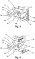
- interlocking spikes (6) if grouped in pairs, are fixed by pairs, as shown in figures 4 , 5 and 6 , by means of the rear end of the inner shaft (13) on both ends of a central arm (9), provided with free rotation movement by means of a shaft (11), with respect to the main support (10) of the assembly.
- the interlocking spikes (6) are provided with multiple chamfers both on the main body (12) and on the end plates (14).
Landscapes
- Engineering & Computer Science (AREA)
- Architecture (AREA)
- Structural Engineering (AREA)
- Mechanical Engineering (AREA)
- Civil Engineering (AREA)
- Transportation (AREA)
- Joining Of Building Structures In Genera (AREA)
- Forms Removed On Construction Sites Or Auxiliary Members Thereof (AREA)
- Conveying And Assembling Of Building Elements In Situ (AREA)
- Movable Scaffolding (AREA)
Claims (12)
- - System, aufweisend- eine selbstkletternde Struktur für eine senkrechte oder nahezu senkrechte Betonfläche, wobei die Kletterstruktur Rahmen (4a, 4b und 4c) aufweist und- eine Ankeranordnung,wobei die Ankeranordnung aufweist- mehrere Metalleinsätze (5), die an einer inneren Bewehrung eines Segments der vertikalen oder nahezu vertikalen Betonoberfläche befestigbar sind, die so konfiguriert sind, dass sie Öffnungen in einer Wand des Segments bilden, und die in verschiedenen Höhen auf der vertikalen oder nahezu vertikalen Betonoberfläche (1) verteilbar sind,- ineinandergreifende Dornen (6), die zum Einstecken und Ankuppeln in die Metalleinsätze (5) geeignet sind und sich in den Rahmen (4a, 4b und 4c) der selbstkletternden Konstruktion (2) befinden, wobei die ineinandergreifenden Dorne (6) mit Mitteln zur horizontalen und vertikalen Verschiebung (7) und mit Annäherungs- und Abstandsvorrichtungen (8) in Bezug auf die senkrechte oder nahezu senkrechte Betonoberfläche (1) vorgesehen sind,dadurch gekennzeichnet, dass
die ineinandergreifenden Dornen (6) aufweisen- eine innere Welle (13), die mit einem kugelförmigen Ende versehen ist,- einen Hauptkörper (12), der das kugelförmige Ende der inneren Welle (13) umhüllt und in Bezug auf dieses mit einer freien Rotationsbewegung versehen ist, wobei der untere Teil des Hauptkörpers (12) halbkreisförmig ist, und- Endplatten (14), die an den vorderen und hinteren Enden des Hauptkörpers (12) befestigt sind und an der Unterseite aus dem Hauptkörper (12) herausragen. - - System nach Anspruch 1, wobei die Metalleinsätze (5) als Hohlkörper (15) ausgebildet sind, die an beiden Enden durch zwei umlaufende Endflächen (16) einer größeren Größe abgeschlossen sind, die eine gemeinsame Durchgangsöffnung definieren.
- - System nach Anspruch 1 oder 2, wobei die durch die Metalleinsätze (5) gebildeten Öffnungen in der Wand Durchgangsöffnungen sind.
- - System nach Anspruch 1 oder 2, wobei die durch die Metalleinsätze (5) gebildeten Öffnungen in der Wand keine Durchgangsöffnungen sind und eine Mulde oder Nische bilden.
- - System nach einem der vorhergehenden Ansprüche, wobei die ineinandergreifenden Dorne (6) jeweils einer für jeden Rahmen (4a, 4b und 4c) verteilt sind, wobei die Metalleinsätze (5) vertikal ausgerichtet angeordnet sind, wobei einer in jeder Höhe für das Herstellen einer Kopplung auf der vertikalen oder nahezu vertikalen Betonoberfläche (1) vorgesehen ist.
- - System nach einem der vorhergehenden Ansprüche, wobei die ineinandergreifenden Dorne (6) paarweise in gleicher Höhe auf jeden Rahmen (4a, 4b und 4c) verteilt sind, wobei die Metalleinsätze (5) vertikal ausgerichtet in Zweiergruppen auf gleicher Höhe verteilt sind, wobei jede für die Kopplung auf der vertikalen oder nahezu senkrechten Betonoberfläche (1) festgelegte Höhe festgelegt ist.
- - System nach einem der vorhergehenden Ansprüche, wobei die ineinandergreifenden Dorne (6) paarweise mittels des hinteren Endes der inneren Welle (13) an beiden Enden eines Mittelarms (9) befestigt sind, der mittels einer Welle (11) in Bezug auf die Hauptstütze (10) der Baugruppe mit einer freien Drehbewegung versehen ist.
- - System nach einem der vorhergehenden Ansprüche, wobei die Rahmen (4a, 4b und 4c) selbstmotorisch und entlang der selbstkletternden Struktur (2) beweglich sind.
- - System nach einem der vorhergehenden Ansprüche, wobei zwei der Rahmen (4b und 4c) selbstmotorisch und entlang der selbstkletternden Struktur (2) beweglich sind, und mindestens einer von ihnen ein Rahmen (4a) ist, der an der selbstkletternden Struktur (2) befestigt ist.
- - System nach einem der vorhergehenden Ansprüche, wobei die ineinandergreifenden Dorne (6) sowohl am Hauptkörper (12) als auch an den Endplatten (14) mit mehreren Fasen versehen sind.
- - System nach einem der vorhergehenden Ansprüche, wobei die Metalleinsätze (5) eine Form annehmen, die aus der Gruppe aus einer kreisförmigen Form und einer Knopflochform ausgewählt ist, bei der der obere Teil breiter ist als der untere, wobei der untere Teil halbkreisförmig ist.
- - System nach Anspruch 1, wobei in einer Kupplungsposition die ineinandergreifenden Dorne (6) in einige der Metalleinsätze (5) eingesetzt werden, und zwar in der Weise, dass der untere Teil jedes Hauptkörpers (12) des ineinandergreifenden Dorns (6) mit dem inneren Teil des Hohlkörpers (15) des entsprechenden Metalleinsatzes (5) in Berührung kommt, wobei die Endplatten (14) an den umlaufenden Endflächen (16) der Metalleinsätze (5) anliegen.
Applications Claiming Priority (2)
| Application Number | Priority Date | Filing Date | Title |
|---|---|---|---|
| ES201930707A ES2804038B2 (es) | 2019-07-30 | 2019-07-30 | Anclaje para estructura autotrepante |
| PCT/ES2020/070463 WO2021019114A1 (es) | 2019-07-30 | 2020-07-16 | Anclaje para estructura autotrepante |
Publications (3)
| Publication Number | Publication Date |
|---|---|
| EP4006265A1 EP4006265A1 (de) | 2022-06-01 |
| EP4006265A4 EP4006265A4 (de) | 2023-07-19 |
| EP4006265B1 true EP4006265B1 (de) | 2025-02-19 |
Family
ID=74215577
Family Applications (1)
| Application Number | Title | Priority Date | Filing Date |
|---|---|---|---|
| EP20847135.9A Active EP4006265B1 (de) | 2019-07-30 | 2020-07-16 | Anker für eine selbstkletternde struktur |
Country Status (13)
| Country | Link |
|---|---|
| US (1) | US20220251858A1 (de) |
| EP (1) | EP4006265B1 (de) |
| JP (1) | JP2022542026A (de) |
| KR (1) | KR20220040457A (de) |
| CN (1) | CN114599848A (de) |
| AU (1) | AU2020320042A1 (de) |
| BR (1) | BR112022001486A2 (de) |
| CA (1) | CA3145781A1 (de) |
| CL (1) | CL2022000059A1 (de) |
| ES (1) | ES2804038B2 (de) |
| MX (1) | MX2022000537A (de) |
| WO (1) | WO2021019114A1 (de) |
| ZA (1) | ZA202200286B (de) |
Families Citing this family (10)
| Publication number | Priority date | Publication date | Assignee | Title |
|---|---|---|---|---|
| ES2695626B2 (es) * | 2017-06-30 | 2020-05-19 | Hws Concrete Towers S L | Dispositivo auto-trepante por superficies de hormigón verticales y cuasi-verticales y procedimiento de operación. |
| ES2804038B2 (es) * | 2019-07-30 | 2021-11-18 | Hws Concrete Towers S L | Anclaje para estructura autotrepante |
| CN116749110A (zh) * | 2022-10-21 | 2023-09-15 | 广东电网有限责任公司韶关供电局 | 电力杆塔导轨拆卸装置 |
| DE102023112172A1 (de) | 2023-03-02 | 2024-09-05 | Liebherr-Werk Biberach Gmbh | Turmdrehkran sowie Verfahren zum Beklettern eines Bauwerks mit einem Turmdrehkran |
| EP4673392A1 (de) | 2023-03-02 | 2026-01-07 | Liebherr-Werk Biberach GmbH | Turmdrehkran sowie verfahren zum beklettern eines bauwerks mit einem turmdrehkran |
| WO2024189465A1 (en) * | 2023-03-10 | 2024-09-19 | Soudure Metalco Inc. | Climbing device |
| CN116677180B (zh) * | 2023-05-25 | 2024-02-09 | 海南大学 | 一种自由移动的施工平台 |
| DE102024124864A1 (de) | 2024-08-30 | 2026-03-05 | Liebherr-Werk Biberach Gmbh | Kran sowie Verfahren zum Beklettern eines Bauwerks mit einem Turmdrehkran |
| DE102024124820A1 (de) | 2024-08-30 | 2026-03-05 | Liebherr-Werk Biberach Gmbh | Kran sowie Verfahren zu dessen Montage an einem Bauwerk |
| DE102024125015A1 (de) | 2024-09-02 | 2026-03-05 | Liebherr-Werk Biberach Gmbh | Kran sowie Verfahren zum Beklettern eines Bauwerks mit einem Turmdrehkran |
Family Cites Families (46)
| Publication number | Priority date | Publication date | Assignee | Title |
|---|---|---|---|---|
| US4770456A (en) * | 1986-12-19 | 1988-09-13 | General Motors Corporation | Robotic end of arm tooling internal gripper |
| US4955655A (en) * | 1988-08-01 | 1990-09-11 | General Motors Corporation | Robotic end-of-arm tooling multiple workpiece internal gripper |
| DE3903575A1 (de) * | 1989-02-07 | 1990-08-09 | Wolfgang Baumann | Im bauwesen zu verwendende haltevorrichtung zum halten von hilfseinrichtungen, insbesondere von gelaenderbrettern oder schalbrettern |
| JPH0470163U (de) * | 1990-09-17 | 1992-06-22 | ||
| DE4200669A1 (de) * | 1992-01-14 | 1993-07-15 | Putzmeister Maschf | Anordnung zum foerdern von beton mit hoehenverstellbarem betonverteilermast |
| ES2085196B1 (es) | 1992-11-12 | 1998-01-16 | Tecnologias Mecanicas De Const | Sistema de encofrado autotrepante y sostenimiento continuo del hormigon. |
| US5645395A (en) * | 1995-06-06 | 1997-07-08 | Huang; Hsin-Tsung | Building crane apparatus climbable on building walls |
| FR2750464B3 (fr) * | 1996-06-25 | 1998-06-05 | Chiou Hsiu Hsing | Attache de securite |
| DE19639038C1 (de) * | 1996-09-23 | 1998-06-04 | Doka Ind Gmbh | Kletterschalungssystem und Verfahren zum sukzessiven Betonieren von hohen vertikalen Wänden |
| JP2000303695A (ja) * | 1999-04-16 | 2000-10-31 | Kumagai Gumi Co Ltd | 免震ビル構築用タワークレーン及びその据付け方法 |
| ES1042982Y (es) * | 1999-05-26 | 2000-02-16 | Peri S A | Anclaje para andamios trepadores. |
| US6557817B2 (en) * | 2000-01-18 | 2003-05-06 | Wilian Holding Company | Wall climbing form hoist |
| CA2317987A1 (en) * | 2000-09-11 | 2002-03-11 | Jean G. Robillard | Improved self-raising platform assembly |
| GB2363817B (en) * | 2001-06-22 | 2002-05-15 | Shire Precast Erection Ltd | Modular building element |
| DE102005030335A1 (de) | 2005-06-29 | 2007-01-04 | Peri Gmbh | Kletterzylinder einer Selbstkletterschalung |
| US7896133B2 (en) * | 2006-02-17 | 2011-03-01 | Jerry Castle | Self-elevating platform scaffolding |
| DE102006040092A1 (de) * | 2006-08-28 | 2008-03-06 | Putzmeister Ag | Anordnung zum Fördern von Beton mit höhenverstellbarem Betonverteilermast |
| DE102006055374B3 (de) | 2006-11-23 | 2008-07-10 | Doka Industrie Gmbh | Kletter-oder Führungsschuh eines Klettersystems im Bauwesen und Klettersystem mit einem derartigen Kletter-oder Führungsschuh |
| DE102008015682A1 (de) | 2008-03-25 | 2009-10-08 | Peri Gmbh | Schienengeführtes Selbstkletterschalungssystem mit Kletterschienen-Verlängerungsstücken |
| PL2365159T3 (pl) * | 2010-03-05 | 2013-07-31 | Ulma C Y E S Coop | Samowznoszący, obwodowy system zabezpieczania dla prac budowlanych w budynkach |
| AU2010350864B2 (en) * | 2010-04-14 | 2016-07-21 | Vsl International Ag | Adjustable formwork climber |
| US9802325B2 (en) * | 2012-03-02 | 2017-10-31 | Magna International Inc. | Robotic end effector tool with one piece fixed frame system |
| DE102012209921A1 (de) * | 2012-06-13 | 2013-12-19 | Areva Gmbh | Greifer |
| RU2015116874A (ru) * | 2012-10-05 | 2016-11-27 | Фипа Гмбх | Манипуляционное устройство, имеющее по меньшей мере один управляемо деформируемый упругий элемент |
| US20160108616A1 (en) * | 2013-05-28 | 2016-04-21 | Total Kankyo Co Ltd | High-rise architectural structure and maintenance method therefor |
| PL2871304T3 (pl) * | 2013-11-12 | 2017-07-31 | Ulma C Y E, S. Coop. | System samowznoszący do zespołów rusztowań w budowie budynków |
| EP3099866B1 (de) * | 2014-01-31 | 2020-09-09 | Gregory John Neighbours | Betonturm und zugehörige schalung sowie zugehöriges konstruktionsverfahren |
| DE202014011125U1 (de) * | 2014-05-26 | 2018-01-11 | Fipa Gmbh | Innengreifer |
| CN204024009U (zh) * | 2014-07-16 | 2014-12-17 | 中国电建集团西北勘测设计研究院有限公司 | 一种风力发电预制混凝土塔架拼装操作平台 |
| IL238098A (en) * | 2015-04-01 | 2016-04-21 | Sky Line Cranes & Technologies Ltd | Modular equipment is adjustable and foldable for climbing crane |
| JP6873144B2 (ja) * | 2015-10-01 | 2021-05-19 | ラガウェイ ウインド ベー.フェー.Lagerwey Wind B.V. | 風力タービンの設置のためのホイスティングシステム |
| CN105484505B (zh) * | 2015-11-24 | 2017-07-21 | 中建三局集团有限公司 | 一种可变角度竖向混凝土结构爬升装置及其使用方法 |
| CN205314542U (zh) * | 2015-11-27 | 2016-06-15 | 中南城建(海南)建设有限公司 | 一种建筑施工液压模板爬升装置 |
| CN107512668A (zh) * | 2016-06-17 | 2017-12-26 | 上海宝冶集团有限公司 | 重力自锁式附墙爬升装置 |
| ES2695626B2 (es) * | 2017-06-30 | 2020-05-19 | Hws Concrete Towers S L | Dispositivo auto-trepante por superficies de hormigón verticales y cuasi-verticales y procedimiento de operación. |
| CN109267738B (zh) * | 2018-12-20 | 2019-03-15 | 上海建工集团股份有限公司 | 一种整体钢平台支撑结构及其调节方法 |
| ES2804038B2 (es) * | 2019-07-30 | 2021-11-18 | Hws Concrete Towers S L | Anclaje para estructura autotrepante |
| US20210362980A1 (en) * | 2020-05-21 | 2021-11-25 | The Tisdale Group, LLC | Mast Climber |
| CN112127613A (zh) * | 2020-09-08 | 2020-12-25 | 深圳市特辰科技股份有限公司 | 一种自动棘轮定位协同受力离心防坠导座的爬架 |
| PL4124366T3 (pl) * | 2021-07-26 | 2024-02-26 | Marcin Pery | Ścianka wspinaczkowa |
| US12337222B2 (en) * | 2022-05-27 | 2025-06-24 | Roy Kaner | Climbing wall in which the climbing route is changed by an automated mechanism |
| DE202022105351U1 (de) * | 2022-09-23 | 2023-01-18 | Dipl.-Ing. Hans Oehm Gesellschaft mit beschränkter Haftung & Co. Kommanditgesellschaft Hoch- und Tiefbau Meppen | Bühne zum Rückbau des Turms einer Windkraftanlage, und Verwendung einer solchen Bühne |
| DE102022126929B3 (de) * | 2022-10-14 | 2024-02-29 | Liebherr-Werk Ehingen Gmbh | Mobilkran mit abnehmbarem Teleskopausleger und Verfahren zum Errichten eines Bauwerks |
| CN116677180B (zh) * | 2023-05-25 | 2024-02-09 | 海南大学 | 一种自由移动的施工平台 |
| CN117646549A (zh) * | 2023-12-25 | 2024-03-05 | 上海建工一建集团有限公司 | 一种整体式升降钢平台系统 |
| CN118065605A (zh) * | 2024-04-02 | 2024-05-24 | 上海宝冶工程技术有限公司 | 用于电梯井道构建工程的自爬升施工系统 |
-
2019
- 2019-07-30 ES ES201930707A patent/ES2804038B2/es active Active
-
2020
- 2020-07-16 MX MX2022000537A patent/MX2022000537A/es unknown
- 2020-07-16 EP EP20847135.9A patent/EP4006265B1/de active Active
- 2020-07-16 KR KR1020227002661A patent/KR20220040457A/ko not_active Ceased
- 2020-07-16 US US17/628,878 patent/US20220251858A1/en not_active Abandoned
- 2020-07-16 CN CN202080055829.5A patent/CN114599848A/zh active Pending
- 2020-07-16 WO PCT/ES2020/070463 patent/WO2021019114A1/es not_active Ceased
- 2020-07-16 CA CA3145781A patent/CA3145781A1/en active Pending
- 2020-07-16 BR BR112022001486A patent/BR112022001486A2/pt not_active Application Discontinuation
- 2020-07-16 JP JP2022503445A patent/JP2022542026A/ja active Pending
- 2020-07-16 AU AU2020320042A patent/AU2020320042A1/en not_active Abandoned
-
2022
- 2022-01-05 ZA ZA2022/00286A patent/ZA202200286B/en unknown
- 2022-01-10 CL CL2022000059A patent/CL2022000059A1/es unknown
Also Published As
| Publication number | Publication date |
|---|---|
| CL2022000059A1 (es) | 2022-08-26 |
| WO2021019114A1 (es) | 2021-02-04 |
| ES2804038B2 (es) | 2021-11-18 |
| CN114599848A (zh) | 2022-06-07 |
| US20220251858A1 (en) | 2022-08-11 |
| AU2020320042A1 (en) | 2022-02-17 |
| ZA202200286B (en) | 2022-09-28 |
| EP4006265A4 (de) | 2023-07-19 |
| EP4006265A1 (de) | 2022-06-01 |
| ES2804038A1 (es) | 2021-02-02 |
| MX2022000537A (es) | 2022-02-10 |
| JP2022542026A (ja) | 2022-09-29 |
| BR112022001486A2 (pt) | 2022-06-07 |
| CA3145781A1 (en) | 2021-02-04 |
| KR20220040457A (ko) | 2022-03-30 |
Similar Documents
| Publication | Publication Date | Title |
|---|---|---|
| EP4006265A1 (de) | Anker für eine selbstkletternde struktur | |
| EP3647512B1 (de) | Selbstklettervorrichtung für vertikale und quasi-vertikale betonoberflächen | |
| CN107155336B (zh) | 混凝土塔和相关模架及相关构造方法 | |
| US8297025B2 (en) | Method of building a hybrid tower for a wind generator | |
| CN110230393B (zh) | 一种大型混凝土罐穹顶可爬升高支模支撑体系及安装方法 | |
| EP3660220B1 (de) | Ankerkorb für ein fundament einer windturbine, montageverfahren dafür und fundament einer windturbine | |
| CN111894272A (zh) | 一种智能型施工平台及其安装工艺和施工工艺 | |
| KR20140130688A (ko) | 자동 설치 특성을 갖는 비계 | |
| CN203924662U (zh) | 一种附着式整体升降脚手架 | |
| CN106150057A (zh) | 一种分片式液压提升爬架 | |
| AU6559600A (en) | Method for the production of high, large diameter towers in sliding molding | |
| CN206110636U (zh) | 一种分片式液压提升爬架 | |
| KR101034424B1 (ko) | 추락 방지 기능을 가진 갱폼 가이더 | |
| CN210366717U (zh) | 一种应用于落地式和自爬式整体施工作业平台 | |
| WO2009127007A1 (en) | Climbing mast assembly | |
| KR100539829B1 (ko) | 형강을 이용한 거푸집용 갱폼 인양방법 | |
| KR102810439B1 (ko) | 기초 가이드 프레임을 이용한 교각의 조립 철근 구조체 및 그 시공방법 | |
| KR102786962B1 (ko) | 작업용 케이지가 구비된 거푸집 자동인양시스템 및 이를 이용한 콘크리트 벽체 시공방법 | |
| CN224132516U (zh) | 一种盖梁钢筋骨架安装吊具 | |
| CN116591466B (zh) | 用于设备保护的模板施工方法 | |
| CN212866929U (zh) | 液压自爬升式卸料平台 | |
| KR101101355B1 (ko) | 스페셜 타워 크레인 시스템 | |
| CN121990475A (zh) | 基坑施工升降设备及使用方法 | |
| BR102023015754A2 (pt) | Sistema construtivo para torre telescópica com juntas flutuantes e método de montagem e estabilização | |
| KR200432806Y1 (ko) | 개방 구조물 시공용 갱폼 |
Legal Events
| Date | Code | Title | Description |
|---|---|---|---|
| STAA | Information on the status of an ep patent application or granted ep patent |
Free format text: STATUS: THE INTERNATIONAL PUBLICATION HAS BEEN MADE |
|
| PUAI | Public reference made under article 153(3) epc to a published international application that has entered the european phase |
Free format text: ORIGINAL CODE: 0009012 |
|
| STAA | Information on the status of an ep patent application or granted ep patent |
Free format text: STATUS: REQUEST FOR EXAMINATION WAS MADE |
|
| 17P | Request for examination filed |
Effective date: 20220119 |
|
| AK | Designated contracting states |
Kind code of ref document: A1 Designated state(s): AL AT BE BG CH CY CZ DE DK EE ES FI FR GB GR HR HU IE IS IT LI LT LU LV MC MK MT NL NO PL PT RO RS SE SI SK SM TR |
|
| DAV | Request for validation of the european patent (deleted) | ||
| DAX | Request for extension of the european patent (deleted) | ||
| A4 | Supplementary search report drawn up and despatched |
Effective date: 20230615 |
|
| RIC1 | Information provided on ipc code assigned before grant |
Ipc: B66C 23/32 20060101ALI20230609BHEP Ipc: B66C 23/20 20060101ALI20230609BHEP Ipc: E04G 3/28 20060101ALI20230609BHEP Ipc: E04G 11/28 20060101ALI20230609BHEP Ipc: E04G 5/04 20060101AFI20230609BHEP |
|
| STAA | Information on the status of an ep patent application or granted ep patent |
Free format text: STATUS: EXAMINATION IS IN PROGRESS |
|
| RIN1 | Information on inventor provided before grant (corrected) |
Inventor name: DIEGO GARAMENDI, RICARDO Inventor name: SAIZ GARCIA, SERGIO Inventor name: MARTINEZ MARTINEZ, AMAIA Inventor name: SORAZU ECHAVE, JOSE MANUEL Inventor name: PEREZ ABADIA, MARIANO Inventor name: MONTANER FRAGUEET, JESUS |
|
| 17Q | First examination report despatched |
Effective date: 20240227 |
|
| GRAP | Despatch of communication of intention to grant a patent |
Free format text: ORIGINAL CODE: EPIDOSNIGR1 |
|
| STAA | Information on the status of an ep patent application or granted ep patent |
Free format text: STATUS: GRANT OF PATENT IS INTENDED |
|
| INTG | Intention to grant announced |
Effective date: 20240916 |
|
| GRAS | Grant fee paid |
Free format text: ORIGINAL CODE: EPIDOSNIGR3 |
|
| GRAA | (expected) grant |
Free format text: ORIGINAL CODE: 0009210 |
|
| STAA | Information on the status of an ep patent application or granted ep patent |
Free format text: STATUS: THE PATENT HAS BEEN GRANTED |
|
| AK | Designated contracting states |
Kind code of ref document: B1 Designated state(s): AL AT BE BG CH CY CZ DE DK EE ES FI FR GB GR HR HU IE IS IT LI LT LU LV MC MK MT NL NO PL PT RO RS SE SI SK SM TR |
|
| REG | Reference to a national code |
Ref country code: GB Ref legal event code: FG4D |
|
| REG | Reference to a national code |
Ref country code: CH Ref legal event code: EP |
|
| REG | Reference to a national code |
Ref country code: IE Ref legal event code: FG4D |
|
| REG | Reference to a national code |
Ref country code: DE Ref legal event code: R096 Ref document number: 602020046489 Country of ref document: DE |
|
| REG | Reference to a national code |
Ref country code: NL Ref legal event code: MP Effective date: 20250219 |
|
| PG25 | Lapsed in a contracting state [announced via postgrant information from national office to epo] |
Ref country code: RS Free format text: LAPSE BECAUSE OF FAILURE TO SUBMIT A TRANSLATION OF THE DESCRIPTION OR TO PAY THE FEE WITHIN THE PRESCRIBED TIME-LIMIT Effective date: 20250519 |
|
| PG25 | Lapsed in a contracting state [announced via postgrant information from national office to epo] |
Ref country code: FI Free format text: LAPSE BECAUSE OF FAILURE TO SUBMIT A TRANSLATION OF THE DESCRIPTION OR TO PAY THE FEE WITHIN THE PRESCRIBED TIME-LIMIT Effective date: 20250219 |
|
| PG25 | Lapsed in a contracting state [announced via postgrant information from national office to epo] |
Ref country code: PL Free format text: LAPSE BECAUSE OF FAILURE TO SUBMIT A TRANSLATION OF THE DESCRIPTION OR TO PAY THE FEE WITHIN THE PRESCRIBED TIME-LIMIT Effective date: 20250219 |
|
| PG25 | Lapsed in a contracting state [announced via postgrant information from national office to epo] |
Ref country code: ES Free format text: LAPSE BECAUSE OF FAILURE TO SUBMIT A TRANSLATION OF THE DESCRIPTION OR TO PAY THE FEE WITHIN THE PRESCRIBED TIME-LIMIT Effective date: 20250219 |
|
| REG | Reference to a national code |
Ref country code: LT Ref legal event code: MG9D |
|
| PG25 | Lapsed in a contracting state [announced via postgrant information from national office to epo] |
Ref country code: NO Free format text: LAPSE BECAUSE OF FAILURE TO SUBMIT A TRANSLATION OF THE DESCRIPTION OR TO PAY THE FEE WITHIN THE PRESCRIBED TIME-LIMIT Effective date: 20250519 Ref country code: IS Free format text: LAPSE BECAUSE OF FAILURE TO SUBMIT A TRANSLATION OF THE DESCRIPTION OR TO PAY THE FEE WITHIN THE PRESCRIBED TIME-LIMIT Effective date: 20250619 |
|
| PG25 | Lapsed in a contracting state [announced via postgrant information from national office to epo] |
Ref country code: NL Free format text: LAPSE BECAUSE OF FAILURE TO SUBMIT A TRANSLATION OF THE DESCRIPTION OR TO PAY THE FEE WITHIN THE PRESCRIBED TIME-LIMIT Effective date: 20250219 |
|
| PG25 | Lapsed in a contracting state [announced via postgrant information from national office to epo] |
Ref country code: HR Free format text: LAPSE BECAUSE OF FAILURE TO SUBMIT A TRANSLATION OF THE DESCRIPTION OR TO PAY THE FEE WITHIN THE PRESCRIBED TIME-LIMIT Effective date: 20250219 |
|
| PG25 | Lapsed in a contracting state [announced via postgrant information from national office to epo] |
Ref country code: LV Free format text: LAPSE BECAUSE OF FAILURE TO SUBMIT A TRANSLATION OF THE DESCRIPTION OR TO PAY THE FEE WITHIN THE PRESCRIBED TIME-LIMIT Effective date: 20250219 Ref country code: PT Free format text: LAPSE BECAUSE OF FAILURE TO SUBMIT A TRANSLATION OF THE DESCRIPTION OR TO PAY THE FEE WITHIN THE PRESCRIBED TIME-LIMIT Effective date: 20250620 |
|
| PG25 | Lapsed in a contracting state [announced via postgrant information from national office to epo] |
Ref country code: GR Free format text: LAPSE BECAUSE OF FAILURE TO SUBMIT A TRANSLATION OF THE DESCRIPTION OR TO PAY THE FEE WITHIN THE PRESCRIBED TIME-LIMIT Effective date: 20250520 Ref country code: BG Free format text: LAPSE BECAUSE OF FAILURE TO SUBMIT A TRANSLATION OF THE DESCRIPTION OR TO PAY THE FEE WITHIN THE PRESCRIBED TIME-LIMIT Effective date: 20250219 |
|
| REG | Reference to a national code |
Ref country code: AT Ref legal event code: MK05 Ref document number: 1768402 Country of ref document: AT Kind code of ref document: T Effective date: 20250219 |
|
| PG25 | Lapsed in a contracting state [announced via postgrant information from national office to epo] |
Ref country code: SE Free format text: LAPSE BECAUSE OF FAILURE TO SUBMIT A TRANSLATION OF THE DESCRIPTION OR TO PAY THE FEE WITHIN THE PRESCRIBED TIME-LIMIT Effective date: 20250219 |
|
| PG25 | Lapsed in a contracting state [announced via postgrant information from national office to epo] |
Ref country code: SM Free format text: LAPSE BECAUSE OF FAILURE TO SUBMIT A TRANSLATION OF THE DESCRIPTION OR TO PAY THE FEE WITHIN THE PRESCRIBED TIME-LIMIT Effective date: 20250219 |
|
| PG25 | Lapsed in a contracting state [announced via postgrant information from national office to epo] |
Ref country code: DK Free format text: LAPSE BECAUSE OF FAILURE TO SUBMIT A TRANSLATION OF THE DESCRIPTION OR TO PAY THE FEE WITHIN THE PRESCRIBED TIME-LIMIT Effective date: 20250219 |
|
| PG25 | Lapsed in a contracting state [announced via postgrant information from national office to epo] |
Ref country code: IT Free format text: LAPSE BECAUSE OF FAILURE TO SUBMIT A TRANSLATION OF THE DESCRIPTION OR TO PAY THE FEE WITHIN THE PRESCRIBED TIME-LIMIT Effective date: 20250219 |
|
| PG25 | Lapsed in a contracting state [announced via postgrant information from national office to epo] |
Ref country code: AT Free format text: LAPSE BECAUSE OF FAILURE TO SUBMIT A TRANSLATION OF THE DESCRIPTION OR TO PAY THE FEE WITHIN THE PRESCRIBED TIME-LIMIT Effective date: 20250219 |
|
| PG25 | Lapsed in a contracting state [announced via postgrant information from national office to epo] |
Ref country code: EE Free format text: LAPSE BECAUSE OF FAILURE TO SUBMIT A TRANSLATION OF THE DESCRIPTION OR TO PAY THE FEE WITHIN THE PRESCRIBED TIME-LIMIT Effective date: 20250219 Ref country code: CZ Free format text: LAPSE BECAUSE OF FAILURE TO SUBMIT A TRANSLATION OF THE DESCRIPTION OR TO PAY THE FEE WITHIN THE PRESCRIBED TIME-LIMIT Effective date: 20250219 |
|
| PG25 | Lapsed in a contracting state [announced via postgrant information from national office to epo] |
Ref country code: RO Free format text: LAPSE BECAUSE OF FAILURE TO SUBMIT A TRANSLATION OF THE DESCRIPTION OR TO PAY THE FEE WITHIN THE PRESCRIBED TIME-LIMIT Effective date: 20250219 |
|
| PG25 | Lapsed in a contracting state [announced via postgrant information from national office to epo] |
Ref country code: SK Free format text: LAPSE BECAUSE OF FAILURE TO SUBMIT A TRANSLATION OF THE DESCRIPTION OR TO PAY THE FEE WITHIN THE PRESCRIBED TIME-LIMIT Effective date: 20250219 |
|
| REG | Reference to a national code |
Ref country code: DE Ref legal event code: R097 Ref document number: 602020046489 Country of ref document: DE |
|
| PLBE | No opposition filed within time limit |
Free format text: ORIGINAL CODE: 0009261 |
|
| STAA | Information on the status of an ep patent application or granted ep patent |
Free format text: STATUS: NO OPPOSITION FILED WITHIN TIME LIMIT |
|
| REG | Reference to a national code |
Ref country code: CH Ref legal event code: L10 Free format text: ST27 STATUS EVENT CODE: U-0-0-L10-L00 (AS PROVIDED BY THE NATIONAL OFFICE) Effective date: 20251231 |
|
| 26N | No opposition filed |
Effective date: 20251120 |
|
| REG | Reference to a national code |
Ref country code: DE Ref legal event code: R119 Ref document number: 602020046489 Country of ref document: DE |
|
| REG | Reference to a national code |
Ref country code: CH Ref legal event code: H13 Free format text: ST27 STATUS EVENT CODE: U-0-0-H10-H13 (AS PROVIDED BY THE NATIONAL OFFICE) Effective date: 20260224 |
|
| PG25 | Lapsed in a contracting state [announced via postgrant information from national office to epo] |
Ref country code: LU Free format text: LAPSE BECAUSE OF NON-PAYMENT OF DUE FEES Effective date: 20250716 |
|
| GBPC | Gb: european patent ceased through non-payment of renewal fee |
Effective date: 20250716 |
|
| REG | Reference to a national code |
Ref country code: BE Ref legal event code: MM Effective date: 20250731 |
|
| PG25 | Lapsed in a contracting state [announced via postgrant information from national office to epo] |
Ref country code: GB Free format text: LAPSE BECAUSE OF NON-PAYMENT OF DUE FEES Effective date: 20250716 |
|
| PG25 | Lapsed in a contracting state [announced via postgrant information from national office to epo] |
Ref country code: DE Free format text: LAPSE BECAUSE OF NON-PAYMENT OF DUE FEES Effective date: 20260203 |
|
| PG25 | Lapsed in a contracting state [announced via postgrant information from national office to epo] |
Ref country code: BE Free format text: LAPSE BECAUSE OF NON-PAYMENT OF DUE FEES Effective date: 20250731 |
|
| PG25 | Lapsed in a contracting state [announced via postgrant information from national office to epo] |
Ref country code: FR Free format text: LAPSE BECAUSE OF NON-PAYMENT OF DUE FEES Effective date: 20250731 |
|
| PG25 | Lapsed in a contracting state [announced via postgrant information from national office to epo] |
Ref country code: CH Free format text: LAPSE BECAUSE OF NON-PAYMENT OF DUE FEES Effective date: 20250731 |