EP4006266B1 - Haltevorrichtungen für transportanker und transportanker - Google Patents
Haltevorrichtungen für transportanker und transportanker Download PDFInfo
- Publication number
- EP4006266B1 EP4006266B1 EP20210558.1A EP20210558A EP4006266B1 EP 4006266 B1 EP4006266 B1 EP 4006266B1 EP 20210558 A EP20210558 A EP 20210558A EP 4006266 B1 EP4006266 B1 EP 4006266B1
- Authority
- EP
- European Patent Office
- Prior art keywords
- transport anchor
- holding device
- transport
- projection
- magnetic
- Prior art date
- Legal status (The legal status is an assumption and is not a legal conclusion. Google has not performed a legal analysis and makes no representation as to the accuracy of the status listed.)
- Active
Links
Images


Classifications
-
- E—FIXED CONSTRUCTIONS
- E04—BUILDING
- E04G—SCAFFOLDING; FORMS; SHUTTERING; BUILDING IMPLEMENTS OR AIDS, OR THEIR USE; HANDLING BUILDING MATERIALS ON THE SITE; REPAIRING, BREAKING-UP OR OTHER WORK ON EXISTING BUILDINGS
- E04G21/00—Preparing, conveying, or working-up building materials or building elements in situ; Other devices or measures for constructional work
- E04G21/14—Conveying or assembling building elements
- E04G21/142—Means in or on the elements for connecting same to handling apparatus
-
- B—PERFORMING OPERATIONS; TRANSPORTING
- B66—HOISTING; LIFTING; HAULING
- B66C—CRANES; LOAD-ENGAGING ELEMENTS OR DEVICES FOR CRANES, CAPSTANS, WINCHES, OR TACKLES
- B66C1/00—Load-engaging elements or devices attached to lifting or lowering gear of cranes or adapted for connection therewith for transmitting lifting forces to articles or groups of articles
- B66C1/10—Load-engaging elements or devices attached to lifting or lowering gear of cranes or adapted for connection therewith for transmitting lifting forces to articles or groups of articles by mechanical means
- B66C1/62—Load-engaging elements or devices attached to lifting or lowering gear of cranes or adapted for connection therewith for transmitting lifting forces to articles or groups of articles by mechanical means comprising article-engaging members of a shape complementary to that of the articles to be handled
- B66C1/66—Load-engaging elements or devices attached to lifting or lowering gear of cranes or adapted for connection therewith for transmitting lifting forces to articles or groups of articles by mechanical means comprising article-engaging members of a shape complementary to that of the articles to be handled for engaging holes, recesses, or abutments on articles specially provided for facilitating handling thereof
- B66C1/666—Load-engaging elements or devices attached to lifting or lowering gear of cranes or adapted for connection therewith for transmitting lifting forces to articles or groups of articles by mechanical means comprising article-engaging members of a shape complementary to that of the articles to be handled for engaging holes, recesses, or abutments on articles specially provided for facilitating handling thereof for connection to anchor inserts embedded in concrete structures
-
- E—FIXED CONSTRUCTIONS
- E04—BUILDING
- E04G—SCAFFOLDING; FORMS; SHUTTERING; BUILDING IMPLEMENTS OR AIDS, OR THEIR USE; HANDLING BUILDING MATERIALS ON THE SITE; REPAIRING, BREAKING-UP OR OTHER WORK ON EXISTING BUILDINGS
- E04G15/00—Forms or shutterings for making openings, cavities, slits, or channels
- E04G15/04—Cores for anchor holes or the like around anchors embedded in the concrete
Definitions
- Concrete parts are manufactured as precast concrete components in precast concrete plants and then transported to construction sites for installation.
- a transport anchor is used to transport these precast concrete parts to and on the construction site. This is cast into the concrete shells and can be brought into engagement with external transport means.
- Such transport anchors can have a connecting sleeve with an internal thread as a threaded anchor, whereby a threaded bolt, threaded pin or threaded mandrel of the external transport means can be screwed into the connecting sleeve for transport.
- the transport anchors are detachably and temporarily fixed to the formwork wall before the formwork is poured with flowable concrete, so that the connecting sleeve is accessible for the means of transport after the concrete has hardened and the formwork wall has been removed.
- the anchors can be fixed to the formwork wall using a magnetic holding force provided by a permanent magnetic holding magnet.
- holding discs are known in which permanent magnets are inserted or sunk on a first side, so that a magnetic holding force with a magnetizable, in particular ferromagnetic or soft magnetic, formwork wall.
- Devices for forming a detachable plug or screw connection with the connecting sleeve are arranged on a second side of the holding disks.
- the base has permanent magnets attached to the side associated with the formwork wall for detachably fastening a threaded anchor to the formwork wall while the formwork is being poured with concrete.
- the base has a threaded mandrel on the side facing away from the formwork wall, onto which the threaded anchor is screwed.
- Another base is in the EP 3 147 094 A2 designed as a base plate.
- the base plate is permanently magnetic in order to adhere to a ferromagnetic receiving area of a formwork wall.
- the base plate has a threaded bolt for coupling to a threaded sleeve of a transport anchor.
- Screwing the connecting sleeves onto the threaded mandrel or the threaded bolt is time-consuming and susceptible to wear and damage.
- the one-sided magnetic holding devices known in the state of the art must be removed from the connecting sleeve by unscrewing the thread.
- the problem is often that the worker incorrectly determines the loosening direction of the thread and, as a result of improper force, breaks off the threaded mandrel, making the holding device unusable. If the threaded mandrel cannot be replaced, the entire magnetic holding device must be replaced, which increases the manufacturing costs for concrete parts.
- Plug-in connections between the holding device and a threaded sleeve of the transport anchor can avoid the problem of the threaded connection.
- plug-in systems in which the threaded sleeve is plugged onto a projection of the one-sided magnetic holding device with an O-ring (https://www.pfei-fer.info/de/ effort-worth/ effort/betoneinbaumaschinemaschine/befest Trentstechnik/schraegstuetzen-befest Trent-fuer-mofi.html, (accessed on November 17, 2020).
- plug connections are often not suitable for holding a threaded sleeve during concreting, i.e.
- the AU 725 226 B3 relates to a double-sided magnetic holding device with a base and a projection.
- the holding device is made of a strong magnetic material, e.g. neodymium.
- the diameter of the projection is designed so that it can be slid into a threaded receptacle of an anchor sleeve.
- the magnets on the second side of the magnetic holding device are weaker than the magnet on the first side. This is to ensure that the holding device remains on the formwork.
- the AU 2009217422 B2 concerns a hemispherical, multi-part holding device.
- the hemisphere can be folded open using a hinge, and when folded up it holds a flat transport anchor. Magnetic holding forces are used to attach the hemisphere halves to each other and to the transport anchor in addition to frictional and positive locking connections.
- the EP 20 210 558 A1 relates to a hemispherical holding device with a recess for a transport anchor. The transport anchor is held magnetically in the holding device.
- An anchor is attached to a steel casing using a magnetic body.
- the magnetic body is covered by a protective cap, whereby several protective caps can be formed as part of a frame body.
- the US 6 434 894 B2 relates to an arrangement for temporarily and/or detachably holding a formwork element with a U-shaped cross-section on a formwork wall.
- a permanent magnet can be inserted into the formwork element. In an assembled state, the permanent magnet forms a magnetically adhesive connection with a formwork wall and closes with the U-legs of the formwork element flush.
- the invention is based on the object of improving the state of the art and providing a magnetic holding device that simplifies and accelerates the assembly and disassembly of the transport anchors in the formwork.
- a further object of the invention is an arrangement for realizing a recessed installation of transport anchors in a concrete part.
- the invention relates to a double-sided or multi-sided permanent magnetic holding device, according to claim 1, for temporarily and/or detachably holding a magnetizable transport anchor on a magnetizable formwork wall of a formwork for producing a concrete part.
- the holding device has a base that is completely or partially made of permanent magnetic material to generate a magnetic adhesive force, wherein the base has a first side for forming a magnetic adhesive force with the formwork wall by magnetizing the formwork wall and a second side, facing away from the formwork wall or not associated with it, for forming a magnetic adhesive force with the transport anchor.
- the second side of the base or the base has a projection or a recess that can be coupled to a recess or a projection of the transport anchor to form a plug connection held together by a magnetic adhesive force.
- the screw connections or frictionally held plug connections between the holding device and the transport anchor known in the prior art are replaced by a connection provided by magnetic adhesive force.
- the base has a projection or a recess which engages in a complementary recess or a complementary projection of the transport anchor and thereby provides a guide for the transport anchor against lateral slipping of the transport anchor.
- the external shape of the holding device is preferably rotationally symmetrical about a body axis, whereby the projection of the base enables the transport anchor or its connecting sleeve to be aligned coaxially or axially parallel to the body axis of the holding device in the plug connection held together by a magnetic adhesive force.
- the second side of the holding device which is permanently magnetic by means of a permanent magnet, in connection with the projection, always ensures a uniform, firm fit of a connecting sleeve, in particular the threaded sleeve of the transport anchor, in the area of the second side of the base. This is particularly important when the holding device and/or transport anchor are removed from a loading magazine by robots and placed precisely on the formwork wall. By omitting a screw connection between the transport anchor and the holding device, a major cause of wear and damage is eliminated, which means that material costs for assembly and thus production costs for a concrete part can be saved.
- the double-sided magnetic holding device is ready for use again after being removed from the young, freshly hardened concrete part.
- the time required to equip the formwork wall with the holding device and transport anchor can thus be reduced overall.
- the magnetic forces on both sides of the holding device, in particular on the first side and the second side of the base are substantially equal.
- the permanent magnetic material and the magnetizable material are designed and arranged in such a way that the magnetic adhesive force, in particular the magnetic flux density, for adhering the holding device to the formwork wall and the magnetic adhesive force for adhering the transport anchor to the holding device are essentially the same.
- a magnetizable material with a high magnetic conductivity or a high permeability is used for this, in particular ferromagnetic material or soft magnetic material. If the permanent magnetic material is arranged in the area of the first side of the holding device, the magnetic field is still sufficiently strong in the area of the second side by using a one-piece or multi-piece ferromagnetic or soft magnetic iron body to form the magnetic adhesive force for the plug connection with the transport anchor.
- the permanent magnetic material for generating a magnetic holding force is arranged as a one-piece permanent magnet in the holding device.
- the manufacture or assembly of the holding device is simplified, which can reduce the manufacturing costs. At the same time, a strong and evenly distributed magnetic holding force can be realized.
- a single permanent magnet e.g. an iron body or neodymium body
- the holding device in particular the base and the projection, comprise permanently magnetic material and, by means of the permanently magnetic material, magnetizable material, wherein the magnetizable material is formed in one piece.
- the permanent magnet is preferably designed as a disk that is sunk into a recess in the first side of the base.
- a preferably flat contact surface is arranged to form a flat magnetic adhesive contact with a contact wall of the transport anchor.
- the contact surface is arranged on a shoulder of the projection.
- the contact wall of the transport anchor which is magnetically attached to the contact surface, seals against concrete penetrating into the transport anchor, in particular into the connecting sleeve, on the magnetic surface of the double-sided magnetic base, because this magnetic surface and the contact wall of the transport anchor are brought into contact with each other in a flat and sealing manner by the magnetic adhesive force.
- This ensures that the transport anchor, in particular the connecting sleeve or the magnetic contact surface, is seated evenly and firmly. This reduces the risk of incorrect assembly of the transport anchor on the holding device and facilitates the use of assembly robots, in which the holding device and/or transport anchor are taken by robots from an assembly magazine and placed precisely on the steel formwork of the formwork wall.
- the projection is arranged in the region of the second side of the base and is designed such that it can be coupled to a connecting sleeve of the transport anchor to form a plug connection held together by a magnetic adhesive force.
- the connecting sleeve of the transport anchor is preferably designed as a threaded sleeve with an internal thread.
- the projection can be designed as a circular cylindrical projection and can thus be inserted into the hole in the connecting sleeve or the threaded sleeve in a form-fitting manner.
- the projection can also be designed with a different geometry, e.g. with a hexagon, because the plug connection between the projection and the connecting sleeve is held together by the magnetic adhesive force between the projection and the connecting sleeve. A form-fitting connection is therefore not absolutely necessary.
- the projection has a lateral surface or outer surface for forming a magnetic adhesive contact with an internal thread of the transport anchor.
- the projection is designed with a circular cylindrical projection and can therefore be inserted into the bore of the connecting sleeve or threaded sleeve in a form-fitting manner. This increases the contact area between the projection and the connecting sleeve, which optimizes the magnetic adhesive force between the connecting sleeve and the projection for a particularly stable plug connection.
- the projection can be divided into a first projection section and a second projection section, wherein the first projection section is designed for connection to a transport anchor and the second projection section provides a distance between the base or the formwork wall and the first projection section for a recessed installation of the transport anchor in the concrete part.
- the first projection portion is tapered relative to the second projection portion.
- the contact surface is designed as the front wall of the second projection section to form an adhesive contact with the contact wall of the transport anchor.
- the second projection section starting from the base towards the first projection section is conically tapered.
- the holding device has a channel, a line or another fluid-conducting access for the fluid-conducting connection of the first side with the second side of the holding device.
- the separation of the double-sided magnetic holding device from the transport anchor or from the formwork wall can thus be made even easier.
- the first side is freely accessible to the worker after the formwork wall has been removed.
- a worker can then attach a compressed air or pneumatic gun to the holding device in order to introduce compressed air or compressed air into the channel, the line or the other fluid-conducting access.
- the compressed air means that the pressure in the area of the connecting sleeve and in the area of the second side of the holding device is sufficient to quasi-pneumatically separate the holding device from the transport anchor and throw it out of the concrete part.
- the removal of the holding device from the concreted-in transport anchor is effortless, quick and non-destructive.
- the base and/or the projection are penetrated by one or more bores to form the channel, the line or the other fluid-conducting access, preferably along or axially parallel to a body axis of the rotationally symmetrical holding device.
- the fluid-conducting connection can be realized using a through hole with a small diameter.
- the compressed air gun can be placed on an opening in the hole in the area of the first side of the holding device and compressed air can be introduced into the holding device.
- the transport anchor has a magnetizable flange disk or other device for enlarging a magnetizable contact wall of the transport anchor to enlarge the contact area between the transport anchor and the holding device.
- a flat disk or other surface is attached to one end of the transport anchor to enlarge the contact wall between the transport anchor and the holding device, along which the magnetic holding force acts.
- the enlarged contact wall can be ring-shaped or have another geometry.
- the enlarged contact wall is made of magnetizable, in particular ferromagnetic or soft magnetic, material.
- a transport anchor comprising a connecting device, in particular a connecting sleeve, for connecting the transport anchor to an external means of transport, an anchoring section for anchoring the transport anchor in a concrete part, wherein the anchoring section has at least one barb element which is produced by bending the anchoring section by more than 90° or is realized in another way, for example by bending, buckling, curving, joining or casting.
- the advantage of creating a barb element is particularly evident when the transport anchor is installed in thin concrete parts, e.g. concrete shells of double walls. If the anchoring section is angled by more than 90°, the anchoring section remains covered by concrete in the concrete part even if a middle section of the anchoring section is no longer covered by concrete. To create the barb, the end of the anchoring section is bent back in the direction of the connecting sleeve. These sections hook into the concrete body and thus reduce the risk of tearing out of the concrete body.
- the anchoring section is divided into two or more anchoring legs, which are each angled by more than 90° in different, preferably opposite, directions or are otherwise realized as barb elements.
- the anchoring section By spreading the anchoring section into several anchoring legs, each of which is designed as barb elements, the anchoring of the anchor in the concrete part is further improved.
- a transport anchor comprising a, preferably cylindrical, connecting sleeve for connecting to an external transport means, wherein the connection between the connecting sleeve and the transport means can preferably be implemented as a screw connection, an anchoring section formed with an anchoring disc for anchoring the transport anchor in a concrete part, wherein the anchoring disc is arranged on or in the region of an end face of the connecting sleeve and wherein, when the concrete part is lifted, the anchoring disc is penetrated or can be penetrated by the transport means and the connecting sleeve exerts or transmits or distributes a compressive force on the anchoring disc during lifting.
- the connecting sleeve in particular the threaded sleeve, is arranged under the anchoring disc when the concrete part is lifted with the transport means.
- the transport means transfers the load to the connecting sleeve and the connecting sleeve in turn to the anchoring disc arranged above the connecting sleeve.
- the connecting sleeve rests against the anchoring disc.
- the connecting sleeve would have to be pulled through the anchoring disc for the transport anchor to fail.
- the transport anchor according to the invention is therefore significantly more reliable than the flat steel anchors known in the prior art.
- the connecting sleeves of the transport anchors can also be used to attach inclined supports of double walls.
- the connecting sleeve is manufactured in one piece with the anchoring disc, preferably by deep drawing.
- the connecting sleeve is welded onto the anchoring disc, which is complex and requires a lot of energy.
- a deep-drawing step simplifies the manufacturing process and reduces energy consumption.
- a cap preferably made of plastic, is attached to the connecting sleeve in a fluid-tight manner to provide a cavity for the transport means.
- such a plastic cap prevents flowable concrete from entering the connecting sleeve when the formwork is poured.
- the plastic cap can leave a cavity in the concrete part into which a threaded mandrel or threaded bolt for transport equipment or other assembly supports can be screwed when the connecting sleeve is completely penetrated by the threaded mandrel or threaded bolt. With such transport anchors, the amount of material used is minimal.
- the cap is placed on the connecting sleeve on a side of the connecting sleeve facing away from the anchoring disc.
- the anchoring disc is arranged or can be arranged between the connecting device, in particular the connecting sleeve, and the formwork wall and is completely penetrated by the first projection section of the holding device during the pouring of the formwork with flowable concrete.
- the arrangement between the transport anchor and the holding device can be implemented with a double-sided magnetic holding device forming a plug connection held by a magnetic adhesive force or with a magnetic holding disk already known in the prior art, in which the connecting sleeve is plugged or screwed onto the threaded mandrel or threaded bolt.
- the anchoring disk is arranged in the area of the upper edge of the concrete.
- the arrangement according to the invention allows the anchoring disk and connecting sleeve to be arranged recessed in the concrete part. Because the transport anchor is arranged recessed, the transport anchor no longer has contact with the environment and is therefore less exposed to environmental influences, in particular corrosive conditions. Access to the recessed transport anchor can be sealed, in particular watertight, with a cap or other prescribed closure. Stainless steel anchors for rust protection reasons can be omitted with a recessed installation.
- a transport anchor in particular a transport anchor in which the threaded sleeve is made by deep-drawing the anchoring disc, has proven particularly advantageous in this arrangement.
- Such a transport anchor in such an arrangement is particularly suitable for recessed installation in the concrete part for fastening supports and struts and for attaching transport equipment.
- the area of the anchoring disc is larger than a contact area of the second projection portion or a cross-sectional area of the second projection portion on or in the region of the anchoring disc.
- the projection can be realized in several parts, wherein an adapter forms the first projection section and at least partially the second projection section.
- one or more adapters can be provided which can be arranged alternatively or cumulatively between the holding device and the transport anchor in order to achieve the planned installation depth.
- the adapter extends the second and/or the first projection section so that the first projection section can be placed sufficiently deep in the flowable concrete to accommodate the connecting sleeve of the transport anchor.
- the adapter i.e. the second projection section
- the adapter can be formed in one piece with the holding device, in particular in one piece with the double-sided magnetic holding disk, in particular as a conical pin.
- the adapter then has a plug-in section at a first end for forming a plug-in connection, preferably held together by a magnetic adhesive force, and a threaded section at a second end for forming a screw connection with the connecting sleeve of the transport anchor.
- a concrete part made of reinforced concrete has a reinforcement insert made of structural steel, with the concrete taking on the pressure and the steel taking on the tension.
- the transport anchors are arranged in the concrete part relative to the steel reinforcement insert in such a way that the steel reinforcement is available to absorb the tensile forces on the transport anchor when the concrete part is lifted or erected.
- the transport anchor is therefore no longer an independent component in the concrete part, but rather the reinforced concrete and transport anchor form a unit, with the reinforcement being used for the transport anchor.
- Figure 1 shows a double-sided magnetic holding device 210 for temporarily and/or releasably holding a magnetizable transport anchor 110, 120, 130 (cf. Fig. 3-7 ) on a magnetizable formwork wall 300 (cf. Fig.4 , 6 , 7 ).
- the external shape of the holding device 210 is rotationally symmetrical about a body axis 215.
- the holding device 210 has a base 211 which is completely or partially covered with permanent magnetic material for generating a magnetic adhesive force with the formwork wall 300 by magnetizing the formwork wall 300 (cf. Fig.6 , 8 , 9 ) is formed.
- the base 211 has a first side 211a for forming a flat magnetic adhesive force with the formwork wall 300.
- the base 211 also has a second side 211b for forming a Plug connection with the transport anchor 110, 120, 130.
- the second side 211b is designed without a thread, the formation of a screw connection between the holding device 210 and the transport anchor 110, 120, 130 is therefore excluded.
- the second side 211b of the base 211 has a permanently magnetic or permanent magnetizable flat contact surface 212 for forming an adhesive contact with a flat contact wall 112, 122 of a connecting sleeve 115, 125, 135 of a transport anchor 110, 120, 130, which seals off flowable concrete.
- a circular cylindrical projection 213 arranged in the area of the second side 211b and parallel to the axis of rotation 215 can be inserted into a connecting sleeve 115, 125, 135.
- the projection 213 forms a guide for the attached transport anchor 110, 120, 130 and centers it on the base 211.
- the projection 213 has a surface 214 for forming a permanent magnetic contact surface or a contact surface that can be magnetized by a permanent magnet for forming a magnetic adhesive contact with an internal thread of the transport anchor 110, 120, 130.
- the connecting sleeve 115, 125, 135 adheres magnetically to the projection 213 without a screw connection or other snap or locking connection being necessary.
- Figure 2 shows a second embodiment of a double-sided magnetic holding device 220.
- the outer shape of the holding device 220 is also rotationally symmetrical about a rotation axis 225.
- the base 221 On or in the area of the second side 221b of the base 221, the base 221 has a projection 223 which can be divided into a first projection section 223a and a second projection section 223b.
- the first projection section 223a preferably corresponds to the projection 213 according to Fig.1 and has a shell surface 224 for forming the magnetic adhesive contact with the internal thread of the transport anchor 110, 120, 130.
- the second projection section 223b provides a distance between the base 221 or the formwork wall 300 and the first projection section 223a for a recessed installation of the transport anchor 110, 120, 130 in the concrete part 301. Therefore, the contact surface 222 is on an end wall of the second projection section 223b and at the base of the first projection section 223a for forming a flat adhesive contact, which seals against flowable concrete, with the contact wall 112, 122 of the connecting sleeve 115, 125, 135 or a flange or anchoring disk 114, 124, 134 of the Transport anchor 110, 120, 130.
- the first projection section 223a is tapered compared to the second projection section 223b or is designed with a reduced radial extension with respect to the rotation axis 225.
- the second projection section 223b tapers evenly from the base 221 to the first projection section 223a.
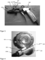
- Fig.3 shows a possibility of quickly and non-destructively releasing the plug connection between the holding device 220 and the transport anchor 110, 120, 130, which is held together by the magnetic adhesive force, in order to be able to reuse the holding device 220.
- the holding device 220 has a channel, a line or another fluid-conducting access 232, wherein a compressed air gun or compressed air pistol 305 can be attached in a fluid-tight manner to an opening of the channel, the line or the access as an inlet 232a for compressed air on or in the area of the first side 221a for fluid-conducting connection of the first side 221a to the second side 221b.
- Fig.3 further shows the permanent magnet 231 designed as a disk that is sunk into a depression 233 of the first side 221a of the base 221. Both the permanent magnet 230 and the magnetizable material 231 are penetrated by the channel, the line or the fluid-conducting access 232. To form the channel, the line or the other fluid-conducting access, the base 221 and the projection 223 are penetrated by a bore that runs along the body axis 225 of the holding device 220.
- an outlet 223b for the compressed air is arranged on the front side of the first projection section 223a or the holding device 220.
- the transport anchor 120 and the holding device 220 please refer to the Figures 2 and 7 referred to.
- Figure 5 shows a transport anchor 110 with a cylindrical connecting sleeve 115, which has an internal thread for screwing in a complementary external thread of a transport means.
- the body axis 111 of the transport anchor preferably coincides with the rotation axis 215,225 of the holding devices 210,220 during installation.
- the connecting sleeve 115 is pressed with an anchoring section 116.
- the back anchoring of the anchoring section 116 is by bending the anchoring section 116 by approximately 45°, but in any case less than 90°.
- a flange disk 114 is mounted in the area of the front side or an opening of the connecting sleeve 115 in order to enlarge the contact wall 112 of the transport anchor 110 for fastening by means of magnetic adhesive force to the flat contact surface 212 of the holding device 210.
- the flange disk 114 forms an anchoring disk 114 as part of the anchoring section 116.
- FIG 6 is part of an arrangement of the transport anchors 110 according to Figure 5 placed on the projection 213 (hidden) in the area of the second side 211b of the holding device 210.
- the holding device 210 is designed with permanent magnetic material in such a way that the first side 211a forms a magnetic adhesive contact with the formwork wall 300 and the second side 211b of the base 211 forms an adhesive contact with the flat front wall 112 of the transport anchor 110, 120, 130.
- the flange-like widening of the transport anchor 110 by means of the flange disk 114 increases the contact wall 112 and consequently the magnetic adhesive force. Fixed in this way, the transport anchor 110 can no longer slip while the formwork is filled with flowable concrete.
- Figure 7 shows a transport anchor 120 with a cylindrical connecting sleeve 125, which has an internal thread as a recess 123 for screwing in a complementary external thread of a threaded mandrel or threaded bolt of an external transport means.
- the body axis 121 of the transport anchor preferably coincides with the rotation axis 215,225 of the holding devices 210,220 during installation.
- the connecting sleeve 125 is produced by deep-drawing the anchoring disk 124 designed as an anchoring section 126 and is thus formed in one piece with the anchoring disk 124.
- a cap 127 made of plastic is placed on the connecting sleeve 125 to seal against the penetration of flowable concrete.
- the cap 127 creates a cavity in the concrete part 301 (cf. Figure 10 ) for screwing a threaded bolt of a means of transport into the connecting sleeve 125.
- the cap 127 is placed on the connecting sleeve 125 on the end face of the connecting sleeve 125 facing away from the anchoring disk 124.
- Figure 8 is part of an arrangement of the transport anchor 125 according to Figure 7 on a contact surface 222 of the second projection portion 223b of a holding device 220 according to Figure 2 fixed magnetically.
- the cap 127 is pushed onto the connecting sleeve 125 so that the connecting sleeve 125 is completely covered.
- the base 221 adheres with its first side 221a (concealed) to the formwork wall 300 so that the holding device 221 and the transport anchor 120 are completely enclosed when the formwork is poured with concrete.
- the anchoring disk 124 thus forms the anchoring section 126 of the transport anchor 120 in the concrete part 301.
- a further transport anchor 130 is mounted on a holding device 210 according to Figure 1 magnetically fixed.
- the body axis 131 of the transport anchor preferably coincides with the rotation axis 215 of the holding devices 210 during installation.
- the transport anchor 130 has an anchoring section 136 produced by pressing with a tubular sleeve for anchoring the transport anchor 130 in a concrete part 301.
- the anchoring section 136 is divided into two or more anchoring legs 137, each of which is bent by more than 90° and is thus implemented as barb elements (139).
- the anchoring section 136 can be formed, for example, by cutting into a compressed section of the anchoring section 136 and spreading the resulting free anchoring legs 137 in different or opposite directions.
- the ends of the anchoring legs 137 thus point essentially in the direction of the concrete upper edge 304.
- the anchoring legs 137 enclose an angle ⁇ of more than 90°, e.g. 135°, with an imaginary extension of the body axis 131.
- the anchoring section 136 or the anchoring legs 137 can be bent, kinked, curved or angled in such a way that an imaginary extension of the bent, curved or angled region or a tangent 138 applied to an outer wall of the bent, curved or angled region facing away from the body axis 131 of the transport anchor 130 encloses a secondary angle ⁇ of more than 90°, preferably 135°, with an imaginary extension of the body axis 131 of the transport anchor facing away from a formwork wall 300 or concrete upper edge 304.
- Figure 10 shows an exemplary concrete part 301 with a transport anchor 120 according to Figure 7 , preferably by means of an arrangement according to Figure 8 manufactured
- a reinforcement insert 303 preferably made of structural steel, is arranged in the concrete part 301 between the upper edge 304 of the concrete and the anchoring disk 124 of the transport anchor 120.
- a holding device 220 with a second projection section 223b to provide a distance between the formwork wall 300 (cf. Fig.8 ) and the transport anchor 120, a recessed installation in the concrete part 301 is realized.
- the second projection section 223b and the base 221 thus simultaneously serve as a recess body for a recess 302 in the concrete body 301.
- This recess 302 forms the access for the external means of transport, so that the threaded bolt of the means of transport can be screwed through the connecting sleeve 125 and into the cavity provided by the cap 127.
- the cap 127 prevents flowable concrete from getting into the recess 123 of the threaded sleeve 125 when the formwork is poured.
- the anchoring disk 124 is firmly anchored in the hardened concrete part 301. No further transport anchor material is required in the area of the recess 302, so material can be saved.
- a connecting sleeve 125 designed as a threaded sleeve has an axial length with respect to the body axis 125 that corresponds to 80% of the dimension of the diameter of the connecting sleeve 125.
- the reinforcement insert 303 between the transport anchor 120 and the concrete upper edge 301 runs along the anchoring disk 124 of the transport anchor 120.
- the connecting sleeve 125 is also arranged on the side of the anchoring disk 124 facing away from the concrete upper edge 304, i.e. when the concrete part 301 is lifted, it is virtually underneath the anchoring disk 124. In order for the transport anchor 120 to fail, the connecting sleeve 125 would have to be pulled through the anchoring disk 124. The load during lifting is distributed from the connecting sleeve 125 to the anchoring disc 124 and from the anchoring disc 124 to the reinforcement insert 303 of the concrete part 301.
- FIG 11 shows an exploded view of an arrangement according to Figure 6 (without formwork wall 300), to which reference is made accordingly.
- Fig.12 shows an exploded view of an arrangement according to Figure 8 (without formwork wall 300), to which reference is made accordingly.
- Fig.13 shows an exploded view of an arrangement according to Figure 12 , wherein an adapter 140 is arranged between the holding device 220 and the transport anchor 120 in order to increase the distance between the base 221 and the anchoring disk 124.
- the adapter 140 has a plug-in section 141 at a first end for forming a plug-in connection held together by a magnetic adhesive force with the second side 221b of the holding device 221.
- the recess for this plug-in connection can have the cross-section of a regular hexagon, suitable for a positive engagement of a tool for unscrewing the adapter 140 from the transport anchor 120 after the concrete part 301 has hardened.
- the adapter 140 has a threaded section for forming a screw connection with the connecting sleeve 125 of the transport anchor 120.
Landscapes
- Engineering & Computer Science (AREA)
- Architecture (AREA)
- Mechanical Engineering (AREA)
- Civil Engineering (AREA)
- Structural Engineering (AREA)
- Joining Of Building Structures In Genera (AREA)
Description
- Die Erfindung betrifft:
- eine doppel- oder mehrseitig dauermagnetische Haltevorrichtung, zum temporären und/oder lösbaren Halten eines magnetisierbaren Transportankers an einer magnetisierbaren Schalungswandung einer Verschalung zur Herstellung eines Betonteils,
- eine Anordnung mit einer doppel- oder mehrseitig dauermagnetischen Haltevorrichtung und einem Transportanker,
- eine Anordnung mit einem Transportanker und einer Haltevorrichtung für einen vertieften Einbau.
- Betonteile werden als Betonfertigbauteile in Betonfertigteilwerken hergestellt und anschließend für den Einbau auf Baustellen transportiert. Zum Transport dieser Betonfertigteile auf die und auf der Baustelle dient ein Transportanker, der in die Betonschalen einbetoniert wird und mit externen Transportmitteln in Eingriff bringbar ist. Solche Transportanker können als Gewindeanker eine Verbindungshülse mit einem Innengewinde aufweisen, wobei in die Verbindungshülse zum Transport ein Gewindebolzen, Gewindezapfen oder Gewindedorn des externen Transportmittels einschraubbar ist.
- Um die Transportanker im Betonteil zu platzieren, werden die Transportanker vor dem Ausgießen der Verschalung mit fließfähigem Beton an der Verschalungswandung lösbar und temporär fixiert, sodass die Verbindungshülse nach dem Aushärten des Betons und dem Entfernen der Verschalungswandung für das Transportmittel zugänglich ist. Das Fixieren an der Verschalungswandung kann mittels einer magnetischen Haftkraft erfolgen, die durch einen dauermagnetischen Haftmagneten bereitgestellt wird.
- Im Stand der Technik sind Haltescheiben bekannt, in die auf einer ersten Seite Dauermagneten eingesetzt oder versenkt sind, sodass eine magnetische Haftkraft mit einer magnetisierbaren, insbesondere ferromagnetischen oder weichmagnetischen, Verschalungswandung ausbildbar ist. Auf einer zweiten Seite der Haltescheiben sind Vorrichtungen zum Ausbilden einer lösbaren Steck- oder Schraubverbindung mit der Verbindungshülse angeordnet.
- In der
DE 102 28 082 A1 ist ein Sockel mit, auf der, der Verschalungswandung zugeordneten, Seite angebrachten, Dauermagneten zur lösbaren Befestigung eines Gewindeankers an der Verschalungswandung während des Ausgießens der Verschalung mit Beton offenbart. Hierfür weist der Sockel auf der, der Verschalungswandung abgewandten, Seite einen Gewindedorn auf, auf dem der Gewindeanker aufgeschraubt ist. - Ein anderer Sockel ist in der
EP 3 147 094 A2 als Sockelscheibe ausgebildet. Die Sockelscheibe ist dauermagnetisch, um an einem ferromagnetischen Aufnahmebereich einer Verschalungswandung anzuhaften. Zu Kopplung mit einer Gewindehülse eines Transportankers weist die Sockelscheibe einen Gewindebolzen auf. - Das Aufschrauben der Verbindungshülsen auf den Gewindedorn bzw. den Gewindebolzen ist zeitaufwändig und anfällig für Verschleiß und Beschädigung. Nach dem das Betonteil gegossen und aus der Verschalung befreit ist, müssen im Stand der Technik bekannte einseitig magnetische Haltemittel durch das Herausschrauben des Gewindes wieder von der Verbindungshülse entfernt werden. Das Problem ist oft, dass der Werker die Löserichtung des Gewindes falsch erfasst und infolge unsachgemäßen Kraftaufwands den Gewindedorn abbricht, sodass die Haltevorrichtung unbrauchbar wird. Kann der Gewindedorn nicht ausgetauscht werden, muss die komplette magnetische Haltevorrichtung ersetzt werden, was die Herstellungskosten für Betonteile erhöht.
- Steckverbindungen zwischen Haltevorrichtung und einer Gewindehülse des Transportankers können das Problem der Gewindeverbindung zwar vermeiden. Es gibt Stecksysteme, bei denen die Gewindehülse auf einen Vorsprung der einseitig magnetischen Haltevorrichtung mit einem O-Ring aufgesteckt wird (https://www.pfei-fer.info/de/produkte-leistungen/produkte/betoneinbauteile/befestigungstechnik/schraegstuetzen-befestigung-mofi/zubehoer/pfeifer-magnetaussparung-fuer-mofi.html, aufgerufen am 17.11.2020). Steckverbindungen sind jedoch oft nicht geeignet, um eine Gewindehülse beim Betonieren, also beim Einfüllen des fließfähigen Betons in die Verschalung, beim Verdichten oder beim Entgasen des Betonteils durch Rütteln zu halten. Es besteht die Gefahr, dass sich die Gewindehülse von dem Steckzapfen löst und aufschwimmt. Dann würde noch fließfähiger Beton in die Gewindehülse eindringen.
- Die
AU 725 226 B3 - Die
AU 2009217422 B2 EP 20 210 558 A1 - In der
KR 102 108 417 B1 - Die
US 6 434 894 B2 betrifft eine Anordnung zum temporären und/oder lösbaren Halten eines Schalungselements mit einem U-förmigen Querschnitt an einer Schalungswandung. In das Schalungselement kann ein Dauermagnet eingesetzt werden. In einem montierten Zustand bildet der Dauermagnet mit einer Schalungswandung eine magnetisch haftende Verbindung aus und schließt dabei mit den U-Schenkeln des Schalungselements bündig ab. - Der Erfindung liegt die Aufgabe zu Grunde, den Stand der Technik zu verbessern und eine magnetische Haltevorrichtung bereitzustellen, die das Montieren und Demontieren der Transportanker in der Verschalung vereinfacht und beschleunigt. Eine weitere Aufgabe der Erfindung besteht in einer Anordnung zur Realisierung eines vertieften Einbaus von Transportankern in einem Betonteil.
- Zur Lösung wird die im Anspruch 1 angegebene doppel- oder mehrseitig dauermagnetische Haltevorrichtung, die im Anspruch 5 angegebene Anordnung mit doppel- oder mehrseitig dauermagnetischer Haltevorrichtung und Transportanker und die im Anspruch 6 angegebene Anordnung vorgeschlagen. Optionale Ausgestaltungen der Erfindung ergeben sich aus den abhängigen Ansprüchen.
- Die Erfindung betrifft eine doppel- oder mehrseitig dauermagnetische Haltevorrichtung, gemäß Anspruch 1, zum temporären und/oder lösbaren Halten eines magnetisierbaren Transportankers an einer magnetisierbaren Schalungswandung einer Verschalung zur Herstellung eines Betonteils. Die Haltevorrichtung weist einen Sockel auf, der ganz oder teilweise mit dauermagnetischem Material zur Erzeugung einer magnetischen Haftkraft ausgebildet ist, wobei der Sockel eine erste Seite zur Ausbildung einer magnetischen Haftkraft mit der Schalungswandung durch Magnetisierung der Schalungswandung und eine zweite, der Schalungswandung abgewandte oder nicht zugeordnete, Seite zur Ausbildung einer magnetischen Haftkraft mit dem Transportanker aufweist. Dabei weist die zweite Seite des Sockels oder der Sockel einen Vorsprung oder eine Vertiefung auf, der mit einer Vertiefung oder einem Vorsprung des Transportankers unter Ausbildung einer durch eine magnetische Haftkraft zusammengehaltenen Steckverbindung koppelbar ist.
- Die im Stand der Technik bekannten Schraubverbindungen oder reibschlüssig zusammengehaltenen Steckverbindungen zwischen der Haltevorrichtung und dem Transportanker werden durch eine magnetische Haftkraft bereitgestellte Verbindung ersetzt. Zusätzlich weist der Sockel einen Vorsprung oder eine Vertiefung auf, die in eine komplementäre Vertiefung oder einen komplementären Vorsprung des Transportankers eingreift und dadurch eine Führung für den Transportanker gegen seitliches Verrutschen des Transportankers bereitstellt. Die äußere Form der Haltevorrichtung ist vorzugsweise rotationssymmetrisch um eine Körperachse ausgebildet, wobei durch den Vorsprung des Sockels der Transportanker bzw. dessen Verbindungshülse in der durch eine magnetische Haftkraft zusammengehaltenen Steckverbindung koaxial oder achsparallel zur Körperachse der Haltevorrichtung ausrichtbar ist. Durch die mittel eines Dauermagneten dauermagnetisch ausgebildete zweite Seite der Haltevorrichtung in Verbindung mit dem Vorsprung ist stets ein gleichmäßiger fester Sitz der einer Verbindungshülse, insbesondere der Gewindehülse der Transportankers, im Bereich der zweiten Seite des Sockels gewährleistet. Die ist besonders dann wichtig, wenn Haltevorrichtung und/oder Transportanker mit Robotern aus einem Bestückungsmagazin entnommen und auf der Verschalungswandung punktgenau platziert werden. Durch den Verzicht auf eine Verschraubung zwischen Transportanker und Haltevorrichtung ist eine wesentliche Ursache für Verschleiß und Beschädigung eliminiert, wodurch Materialkosten für die Montage und damit Herstellungskosten für ein Betonteil eingespart werden können.
- Ebenso entfällt das auswendige Lösen der Schraubverbindung und Trennen der Haltevorrichtung vom Transportanker. Das Trennen der doppelseitig magnetischen Haltevorrichtung vom Transportanker bzw. von der Verschalungswandung erfolgt wie folgt.
- Ist die Haltevorrichtung nach dem Trennen des gehärteten Betonteils von der Verschalungswandung magnetisch haftend am Transportanker geblieben, wird auf der jetzt sichtbaren bzw. frei zugänglichen ersten Seite der Haltevorrichtung eine magnetisierbare oder dauermagnetische Vorrichtung zur Anlage gebracht. Insbesondere wenn die magnetische Haftkraft der ersten Seite stärker ausgebildet ist als die magnetische Haftkraft im Bereich der zweiten Seite, lässt sich nach Anlage der magnetisierbaren oder dauermagnetischen Vorrichtung die doppelseitig magnetische Haltevorrichtung vom Transportanker im Betonteil lösen und die Haltevorrichtung kann von dem im Beton eingebauten Transportanker, insbesondere aus der Gewindehülse genommen werden.
- Haftet die doppelseitig magnetische Haltevorrichtung auf der magnetisierbaren, also ferromagnetischen oder weichmagnetischen Verschalungswandung, kann die Haltevorrichtung entfernt werden, indem auf den Vorsprung der Haltevorrichtung wieder ein Transportanker unter Ausbildung einer durch eine magnetische Haftkraft gehaltenen Steckverbindung gesteckt wird und dieser Transportanker als Hebel zum Kippen und Ablösen der Haltevorrichtung genutzt wird.
- Die doppelseitig magnetische Haltevorrichtung ist nach dem Entfernen aus dem jungen, frisch ausgehärteten, Betonteil wieder einsatzbereit. Die Zeit, die zum Bestücken der Verschalungswandung mit Haltevorrichtung und Transportanker benötigt wird, lässt sich so insgesamt reduzieren.
- Vorzugsweise sind die magnetischen Kräfte auf beiden Seiten der Haltevorrichtung, insbesondere auf der ersten Seite und der zweiten Seite des Sockels, im Wesentlichen gleich.
- Das dauermagnetische Material und das magnetisierbare Material sind so ausgebildet und angeordnet, dass die magnetische Haftkraft, insbesondere die magnetische Flussdichte, zum Haften der Haltevorrichtung an der Verschalungswandung und die magnetische Haftkraft zum Haften des Transportankers an der Haltevorrichtung im Wesentlichen gleich ist. Dafür wird ein magnetisierbares Material mit einer hohen magnetischen Leitfähigkeit bzw. einer hohen Permeabilität verwendet, insbesondere ferromagnetisches Material oder weichmagnetisches Material. Wird das dauermagnetische Material im Bereich der ersten Seite der Haltevorrichtung angeordnet, so ist das Magnetfeld auch im Bereich der zweiten Seite durch Verwendung eines einstückigen oder mehrteiligen ferromagnetischen oder weichmagnetischen Eisenkörpers noch ausreichend stark, um die magnetische Haftkraft für die Steckverbindung mit dem Transportanker auszubilden.
- In einer optionalen Weiterbildung der Erfindung ist das dauermagnetische Material zur Erzeugung einer magnetischen Haftkraft als einstückiger Dauermagnet in der Haltevorrichtung angeordnet.
- Durch die Anordnung eines einzigen Dauermagneten, bspw. ein Eisenkörper oder Neodymkörper, in der Haltevorrichtung ist die Herstellung oder Montage der Haltevorrichtung vereinfacht, womit die Herstellungskosten gesenkt werden können. Gleichzeitig ist entlang der gesamten Oberfläche der Haltevorrichtung eine starke und gleichmäßig verteilte magnetische Haftkraft realisierbar.
- Die Haltevorrichtung, insbesondere der Sockel und der Vorsprung, weisen dauermagnetisches Material und, durch das dauermagnetische Material, magnetisierbares Material auf, wobei das magnetisierbare Material einstückig ausgebildet ist.
- Durch die Anordnung eines einzigen Stücks magnetisierbaren Materials, insbesondere weichmagnetischen oder ferromagnetischen Materials, bspw. eines Eisenkörpers kann das Herstellungsverfahren weiter vereinfacht werden, womit die Herstellungskosten gesenkt werden können. Vorzugsweise ist der Dauermagnet als Scheibe ausgebildet, die in einer Einsenkung der ersten Seite des Sockels versenkt ist.
- Im Bereich der zweiten Seite des Sockels ist eine, vorzugsweise ebene, Kontaktfläche zur Ausbildung eines satt flächigen magnetischen Haftkontakts mit einer Anlagewandung des Transportankers angeordnet.
- Die Kontaktfläche ist an einem Ansatz des Vorsprungs angeordnet. Die an der Kontaktfläche magnetisch haftend angelegte Anlagewandung des Transportankers dichtet auf der magnetischen Oberfläche des doppelseitig magnetischen Sockels gegenüber in den Transportanker, insbesondere in die Verbindungshülse, eindringenden Beton ab, weil diese magnetische Oberfläche und die Anlagewandung des Transportankers durch die magnetische Haftkraft satt flächig und dichtend zur Anlage gebracht werden. Dadurch wird ein gleichmäßiger und fester Sitz des Transportankers, insbesondere der Verbindungshülse oder der magnetischen Kontaktfläche, erreicht. Damit wird die Gefahr einer fehlerhaften Montage des Transportankers an der Haltevorrichtung reduziert und der Einsatz von Bestückungsrobotern erleichtert, bei denen Haltevorrichtung und/oder Transportanker von Robotern aus einem Bestückungsmagazin entnommen und auf der Stahlschalung der Verschalungswandung punktgenau platziert wird.
- Der Vorsprung ist im Bereich der zweiten Seite des Sockels angeordnet und derart ausgebildet, dass er mit einer Verbindungshülse des Transportankers unter Ausbildung einer durch eine magnetische Haftkraft zusammengehaltenen Steckverbindung koppelbar ist.
- Die Verbindungshülse des Transportankers ist vorzugsweise als Gewindehülse mit einem Innengewinde ausgebildet. Der Vorsprung kann als kreiszylindrischer Vorsprung ausgebildet sein und dadurch formschlüssig in die Bohrung der Verbindungshülse bzw. der Gewindehülse eingeschoben werden. Alternativ kann der Vorsprung auch mit einer anderen Geometrie, bspw. mit einem Sechskant ausgebildet sein, weil die Steckverbindung zwischen Vorsprung und Verbindungshülse durch die magnetische Haftkraft zwischen Vorsprung und Verbindungshülse zusammengehalten ist. Ein Formschluss ist daher nicht zwingend nötig.
- Optional weist der Vorsprung eine Mantelfläche oder Außenfläche zur Ausbildung eines magnetischen Haftkontakts mit einem Innengewinde des Transportankers auf.
- Der Vorsprung ist mit kreiszylindrischem Vorsprung ausgebildet und dadurch formschlüssig in die Bohrung der Verbindungshülse bzw. der Gewindehülse einschiebbar. Dadurch wird die Kontaktfläche zwischen dem Vorsprung und der Verbindungshülse vergrößert, womit die magnetische Haftkraft zwischen Verbindungshülse und Vorsprung für eine besonders stabile Steckverbindung optimiert wird.
- Der Vorsprung ist in einen ersten Vorsprung-Abschnitt und in einen zweiten Vorsprung-Abschnitt unterteilbar ist, wobei der erste Vorsprung-Abschnitt zum Verbinden mit einem Transportanker ausgebildet ist und der zweite Vorsprung-Abschnitt einen Abstand zwischen dem Sockel oder der Verschalungswandung und dem ersten Vorsprung-Abschnitt für einen vertieften Einbau des Transportankers im Betonteil bereitstellt.
- Vorzugsweise ist der erste Vorsprung-Abschnitt gegenüber dem zweiten Vorsprung-Abschnitt verjüngt ausgebildet.
- Die Kontaktfläche ist zur Ausbildung eines Haftkontakts mit der Anlagewandung des Transportankers als Stirnwandung des zweiten Vorsprung-Abschnitts ausgebildet.
- Optional ist der zweite Vorsprung-Abschnitt ausgehend von dem Sockel hin zum ersten Vorsprung-Abschnitt konisch verjüngt.
- In einer bevorzugten Ausführungsform der Erfindung weist die Haltevorrichtung einen Kanal, eine Leitung oder einen sonstigen fluidleitenden Zugang zum fluidleitenden Verbinden der ersten Seite mit der zweiten Seite der Haltevorrichtung auf. Das Trennen der doppelseitig magnetischen Haltevorrichtung vom Transportanker bzw. von der Verschalungswandung kann damit weiter vereinfacht werden. Die erste Seite ist nach dem Entfernen der Verschalungswandung für den Werker frei zugänglich. Dann kann ein Werker eine Druckluft- oder Pressluftpistole an der der Haltevorrichtung ansetzen um in den Kanal, die Leitung oder den sonstigen fluidleitenden Zugang Pressluft oder Druckluft einzuleiten. Durch die Druckluft ist der Druck im Bereich der Verbindungshülse und im Bereich der zweiten Seite der Haltevorrichtung ausreichend, um die Haltevorrichtung quasi pneumatisch vom Transportanker zu trennen und aus dem Betonteil zu werfen. Das Entfernen der Haltevorrichtung vom einbetonierten Transportanker erfolgt kraftlos, schnell und zerstörungsfrei.
- In einer optionalen Weiterbildung davon ist zur Ausbildung des Kanals, der Leitung oder des sonstigen fluidleitenden Zugangs der Sockel und/oder der Vorsprung von einer oder mehreren Bohrungen durchsetzt, vorzugsweise entlang oder achsparallel zu einer Körperachse der rotationssymmetrischen Haltevorrichtung.
- Bereits durch eine Durchgangsbohrung mit geringem Durchmesser kann die fluidleitende Verbindung realisiert werden. Die Druckluftpistole kann an einer Öffnung der Bohrung im Bereich der ersten Seite der Haltevorrichtung angesetzt und so Druckluft in die Haltevorrichtung eingeleitet werden.
- Eigenständiger Erfindungsschutz wird beansprucht für eine Anordnung nach Anspruch 5, zum temporären und/oder lösbaren Halten eines Transportankers an einer magnetisierbaren Schalungswandung einer Verschalung zur Herstellung eines Betonteils, aufweisend
- eine doppel- oder mehrseitig dauermagnetische Haltevorrichtung in einer der bereits beschriebenen Ausführungen, ,
- den Transportanker mit einer Einrichtung zum Verbinden mit einem externen Transportmittel, wobei der Transportanker magnetisierbares, insbesondere ferromagnetisches oder weichmagnetisches Material zur Ausbildung einer durch eine magnetische Haftkraft zusammengehaltenen Steckverbindung mit der Haltevorrichtung aufweist.
- In einer bevorzugten Ausführung der Anordnung weist der Transportanker eine magnetisierbare Flanschscheibe oder sonstige Einrichtung zur Vergrößerung einer magnetisierbaren Anlagewandung des Transportankers zur Vergrößerung der Kontaktfläche zwischen dem Transportanker und der Haltevorrichtung auf.
- In anderen Worten, an einer Stirnseite des Transportankers ist eine ebene Scheibe oder sonstige Fläche zur Vergrößerung der Anlagewandung zwischen Transportanker und Haltevorrichtung angebracht, entlang der die magnetische Haftkraft wirkt. Die vergrößerte Anlagewandung kann ringförmig ausgebildet sein oder eine sonstige Geometrie aufweisen. Die vergrößerte Anlagewandung ist aus magnetisierbarem, insbesondere ferromagnetischem oder weichmagnetischem, Material ausgebildet.
- Nicht Teil der Erfindung ist ein Transportanker, aufweisend eine Verbindungseinrichtung, insbesondere eine Verbindungshülse, zum Verbinden des Transportankers mit einem externen Transportmittel, einen Verankerungsabschnitt zur Verankerung des Transportankers in einem Betonteil, wobei der Verankerungsabschnitt mindestens ein Widerhakenelement aufweist, das durch Abwinkeln des Verankerungsabschnitts um mehr als 90° hergestellt ist oder in sonstiger Weise, bspw. durch Biegen, Knicken, Krümmen, Fügen oder Gießen realisiert ist.
- Der Vorteil der Ausbildung eines Widerhakenelements tritt vor Allem dann hervor, wenn der Transportanker in dünne Betonteile, z.B. Betonschalen von Doppelwänden eingebaut wird. Wird der Verankerungsabschnitt um mehr als 90° abgewinkelt, dann bleibt der Verankerungsabschnitt auch dann im Betonteil von Beton bedeckt, wenn ein Mittelabschnitt des Verankerungsabschnitts nicht mehr von Beton bedeckt ist. Zur Realisierung des Widerhakens ist das Ende des Verankerungsabschnitts zurück in die Richtung der Verbindungshülse gebogen. Diese Abschnitte verhaken sich im Betonkörper und verringern so die Gefahr eines Ausreißens aus dem Betonkörper.
- In einer bevorzugten Ausführungsform ist der Verankerungsabschnitt in zwei oder mehr Verankerungsschenkel unterteilt, die in verschiedene, vorzugsweise entgegengesetzte, Richtungen jeweils um mehr als 90° abgewinkelt oder in sonstiger Weise als Widerhakenelemente realisiert sind.
- Durch die Aufspreizung des Verankerungsabschnitts in mehrere Verankerungsschenkel, die jeweils als Widerhakenelemente ausgeführt sind, wird die Rückverankerung des Ankers im Betonteil weiter verbessert.
- Nicht Teil der Erfindung ist ein Transportanker aufweisend eine, vorzugsweise zylindrische, Verbindungshülse zum Verbinden mit einem externen Transportmittel, wobei die Verbindung zwischen der Verbindungshülse und dem Transportmittel vorzugsweise als Schraubverbindung realisierbar ist, einen mit einer Verankerungsscheibe gebildeten Verankerungsabschnitt zur Verankerung des Transportankers in einem Betonteil, wobei die Verankerungsscheibe an oder im Bereich einer Stirnseite der Verbindungshülse angeordnet ist und wobei beim Anheben des Betonteils die Verankerungsscheibe vom Transportmittel durchsetzt oder dursetzbar ist und die Verbindungshülse beim Anheben eine Druckkraft auf den die Verankerungsscheibe ausübt oder überträgt oder verteilt.
- Im Unterschied zu bereits bekannten Flachstahlankern ist die Verbindungshülse, insbesondere die Gewindehülse beim Anheben des Betonteils mit dem Transport mittel unter der Verankerungsscheibe angeordnet. Beim Anheben des Betonteils überträgt das Transportmittel die Last auf die Verbindungshülse und die Verbindungshülse wiederum auf die über der Verbindungshülse angeordnete Verankerungsscheibe. Die Verbindungshülse liegt dabei an der Verankerungsscheibe an. Die Verbindungshülse müsste durch die Verankerungsscheibe gezogen werden, damit der Transportanker versagen würde. Der erfindungsgemäße Transportanker ist daher deutlich betriebssicherer als im Stand der Technik bekannte Flachstahlanker. Die Verbindungshülsen der Transportanker können auch genutzt werden, um Schrägstützen von Doppelwänden zu befestigen.
- Insbesondere ist die Verbindungshülse, vorzugsweise durch Tiefziehen, einstückig mit der Verankerungsscheibe hergestellt.
- Bei im Stand der Technik bekannten Flachstahlankern wird die Verbindungshülse aufwendig und mit hohem Energieverbrauch auf die Verankerungsscheibe geschweißt. Durch einen Tiefziehschritt wird das Herstellungsverfahren vereinfacht und der Energieverbrauch gesenkt.
- In einer bevorzugten Ausführungsform ist an die Verbindungshülse eine Kappe, vorzugsweise aus Kunststoff, zur Bereitstellung eines Hohlraums für das Transportmittel fluiddichtend aufgesteckt.
- Durch eine solche Kunststoffkappe wird einerseits verhindert, dass fließfähiger Beton beim Ausgießen der Verschalung in die Verbindungshülse gelangt. Gleichzeitig kann durch die Kunststoffkappe ein Hohlraum im Betonteil ausgespart bleiben, in den ein Gewindedorn oder Gewindebolzen für Transportmittel oder sonstige Montagestützen einschraubbar ist, wenn die Verbindungshülse von dem Gewindedorn oder Gewindebolzen vollständig durchsetzt ist. Bei solchen Transportankern ist der Materialeinsatz minimal.
- Vorzugsweise ist die Kappe auf einer der Verankerungsscheibe abgewandten Seite der Verbindungshülse auf die Verbindungshülse aufgesteckt.
- Eigenständiger Erfindungsschutz wird beansprucht für eine Anordnung gemäß Anspruch 6, zum temporären und/oder lösbaren Halten eines Transportankers an einer Schalungswandung einer Verschalung zur Herstellung eines Betonteils, aufweisend
- den Transportanker, aufweisend eine Verbindungseinrichtung, insbesondere eine Verbindungshülse, zum Verbinden des Transportankers mit einem externen Transportmittel, eine Verankerungsscheibe als Verankerungsabschnitt zur Verankerung in einem Betonteil,
- eine Haltevorrichtung zur Befestigung des Transportankers an der Verschalungswandung in einer der bereits beschriebenen Ausführungen.
- Dabei ist die Verankerungsscheibe zwischen der Verbindungseinrichtung, insbesondere der Verbindungshülse, und der Verschalungswandung angeordnet oder anordenbar und vom ersten Vorsprung-Abschnitt der Haltevorrichtung, während des Ausgießens der Verschalung mit fließfähigem Beton, vollständig durchsetzt.
- Die Anordnung zwischen Transortanker und Haltevorrichtung kann mit einer doppelseitig magnetischen Haltevorrichtung unter Ausbildung einer durch eine magnetische Haftkraft gehaltenen Steckverbindung oder mit einer im Stand der Technik bereits gekannten Magnethaftscheibe realisiert werden, bei der die Verbindungshülse auf den Gewindedorn oder Gewindebolzen aufgesteckt oder aufgeschraubt wird. Bei den im Stand der Technik bekannten Transportankern ist die Verankerungsscheibe im Bereich der Betonoberkante angeordnet. Durch die erfindungsgemäße Anordnung können Verankerungsscheibe und Verbindungshülse vertieft im Betonteil angeordnet werden. Dadurch, dass der Transportanker vertieft angeordnet ist, hat der Transportanker keinen Kontakt mehr zur Umgebung und ist daher Umgebungseinflüssen, insbesondere korrosiven Bedingungen, weniger stark ausgesetzt. Der Zugang zu dem vertieft eingebauten Transportanker kann mit einer Kappe oder einem sonstigen vorgeschriebenen Abschluss dichtend, insbesondere wasserdicht, verschlossen werden. Edelstahlanker aus Rostschutzgründen können bei einem vertieften Einbau entfallen.
- Besonders vorteilhaft erweist sich im Rahmen dieser Anordnung die Verwendung eines Transportankers, insbesondere eines Transportankers, bei dem die Gewindehülse durch ein Tiefziehen der Verankerungsscheibe realisiert ist. Ein solcher Transportanker in einer solchen Anordnung ist besonders gut zum vertieften Einbau im Betonteil zum Befestigen von Stützen und Streben und zum Anschlagen von Transportmitteln geeignet.
- In einer besonders bevorzugten Ausführungsform der Erfindung ist die Fläche der Verankerungsscheibe größer ist als eine Kontaktfläche des zweiten Vorsprung-Abschnitts oder eine Querschnittsfläche des zweiten Vorsprung-Abschnitts an oder im Bereich der Verankerungsscheibe.
- Dadurch kann die Verankerungsscheibe beidseitig von fließfähigem Beton umströmt werden, sodass die Verankerungsscheibe beidseitig von Beton bedeckt und nach dem Aushärten fest im Betonteil verankert ist. In anderen Worten, Beton gelangt zwischen den Verankerungsabschnitt und die Betonoberkante und spart lediglich einen Zugang zum Einschrauben eines externen Transportmittels oder von Schrägstützen oder Streben aus.
- Der Vorsprung kann mehrteilig realisiert sein, wobei ein Adapter den ersten Vorsprung-Abschnitt und wenigstens bereichsweise den zweiten Vorsprung-Abschnitt ausbildet.
- Im Rahmen der Anordnung können ein oder mehrere Adapter vorgesehen sein, die alternativ oder kumulativ zwischen der Haltevorrichtung und dem Transportanker angeordnet werden können, um so die geplante Einbautiefe zu realisieren. Der Adapter verlängert den zweiten und/oder den ersten Vorsprung-Abschnitt, damit der erste Vorsprung-Abschnitt zur Aufnahme der Verbindungshülse des Transportankers ausreichend tief im fließfähigen Beton platzierbar ist.
- Alternativ kann der Adapter, also der zweite Vorsprung-Abschnitt einstückig mit der Haltevorrichtung, insbesondere einstückig mit der doppelseitig magnetischen Haltescheibe ausgebildet werden, insbesondere als konischer Zapfen. Bezüglich dieser Variante wird auf die obigen Erläuterungen zur doppelseitig magnetischen Haltevorrichtung verwiesen.
- Vorzugsweise weist der Adapter dann an einem ersten Ende einen Steckabschnitt zur Ausbildung einer, vorzugsweise durch eine magnetische Haftkraft zusammengehaltenen, Steckverbindung und an einem zweiten Ende einen Gewindeabschnitt zur Ausbildung einer Schraubverbindung mit der Verbindungshülse des Transportankers auf.
- Kein Teil der Erfindung ist ein Betonteil mit einem Transportanker, wobei der Transportanker eine Verbindungshülse und eine Flansch- oder Verankerungsscheibe aufweist, wobei das Betonteil wiederum aufweist:
- eine Aussparung für einen Zugang für ein externes Transportmittel zum Transportanker im Betonteil, wobei der Transportanker, insbesondere die Verbindungshülse und die Verankerungsscheibe des Transportankers, gegenüber einer Oberkante des Betonteils vertieft oder mit Abstand angeordnet ist,
- eine Bewehrungseinlage, wobei die Bewehrungseinlage entlang der Verankerungsscheibe des Transportankers verläuft oder zwischen der Verankerungsscheibe des Transportankers und der Oberkante angeordnet ist, sodass beim Anheben des Betonteils mit dem Transportmittel die dabei entstehenden Kräfte auf die Bewehrungseinlage verteilt sind.
- Ein Betonteil aus Stahlbeton weist eine Bewehrungseinlage aus Baustahl auf, wobei der Beton den Druck und der Stahl den Zug übernimmt. Bei einem erfindungsgemäßen Betonteil werden die Transportanker so im Betonteil relativ zur Stahlbewehrungseinlage angeordnet, dass die Stahlbewehrung beim Anheben oder Aufrichten des Betonteils zur Aufnahme der Zugkräfte am Transportanker zur Verfügung steht. Der Transportanker bildet also kein eigenständiges Bauteil mehr im Betonteil, vielmehr bilden Stahlbeton und Transportanker eine Einheit, wobei die Bewehrung für den Transportanker genutzt wird.
- Weitere Einzelheiten, Merkmale, Merkmals(unter)kombinationen, Vorteile und Wirkungen auf der Basis der Erfindung ergeben sich aus der nachfolgenden Beschreibung bevorzugter Ausführungsformen der Erfindung und den Zeichnungen. Diese zeigen in
- Fig. 1
- eine nicht erfindungsgemäße magnetische Haltevorrichtung in einer ersten beispielhaften Ausführungsform in perspektivischer Darstellung,
- Fig. 2
- eine erfindungsgemäße magnetische Haltevorrichtung in einer zweiten beispielhaften Ausführungsform in perspektivischer Darstellung,
- Fig. 3
- eine Anordnung der erfindungsgemäßen magnetischen Haltevorrichtung der zweiten beispielhaften Ausführungsform mit Druckluftpistole in perspektivischer Darstellung,
- Fig. 4
- eine Explosionsdarstellung der Anordnung aus magnetischer Haltevorrichtung und Transportanker einer zweiten beispielhaften erfindungsgemäßen Ausführungsform in perspektivischer Darstellung,
- Fig. 5
- einen Transportanker in einer ersten beispielhaften Ausführungsform in perspektivischer Darstellung,
- Fig. 6
- eine nicht erfindungsgemäße Anordnung mit Transportanker und Haltevorrichtung in einer ersten beispielhaften Ausführungsform der Erfindung in perspektivischer Darstellung,
- Fig. 7
- einen nicht erfindungsgemäßen Transportanker in einer zweiten beispielhaften Ausführungsform in perspektivischer Darstellung,
- Fig. 8
- eine erfindungsgemäße Anordnung mit Transportanker und Haltevorrichtung in einer zweiten beispielhaften Ausführungsform in perspektivischer Darstellung,
- Fig. 9
- eine nicht erfindungsgemäße Anordnung mit Transportanker und Haltevorrichtung in einer dritten beispielhaften Ausführungsform in perspektivischer Darstellung,
- Fig. 10
- ein nicht erfindungsgemäßes Betonteil mit Transportanker in einer beispielhaften Ausführungsform als Prinzipskizze, und in
- Fig.11-13
- beispielhafte erfindungsgemäße Anordnungen mit Transportanker und Haltevorrichtung in perspektivischer Explosionsdarstellung.
- Die Figuren sind lediglich beispielhafter Natur und dienen nur dem Verständnis der Erfindung. Die gleichen Elemente sind mit denselben Bezugszeichen versehen.
-
Figur 1 zeigt eine doppelseitige magnetische Haltevorrichtung 210 zum temporären und/oder lösbaren Halten eines magnetisierbaren Transportankers 110, 120, 130 (vgl.Fig. 3-7 ) an einer magnetisierbaren Schalungswandung 300 (vgl.Fig. 4 ,6 ,7 ). Die äußere Form der Haltevorrichtung 210 ist rotationsymmetrisch um eine Körperachse 215 ausgebildet. Die Haltevorrichtung 210 weist einen Sockel 211 auf, der ganz oder teilweise mit dauermagnetischem Material zur Erzeugung einer magnetischen Haftkraft mit der Schalungswandung 300 durch Magnetisierung der Schalungswandung 300 (vgl.Fig. 6 ,8 ,9 ) ausgebildet ist. Dafür weist der Sockel 211 eine erste Seite 211a zur Ausbildung einer flächigen magnetischen Haftkraft mit der Schalungswandung 300 auf. Der Sockel 211 weist ferner eine zweite Seite 211b, zum Ausbilden einer durch eine magnetische Haftkraft zusammengehaltenen Steckverbindung mit dem Transportanker 110, 120, 130 auf. Die zweite Seite 211b ist ohne Gewinde ausgebildet, die Ausbildung einer Schraubverbindung zwischen der Haltevorrichtung 210 und dem Transportanker 110, 120, 130 ist damit ausgeschlossen. Vielmehr weist die zweite Seite 211b des Sockels 211 eine dauermagnetische oder durch einen Dauermagneten magnetisierbare ebene Kontaktfläche 212 zur Ausbildung eines, gegenüber fließfähigem Beton abdichtenden, Haftkontakts mit einer ebenen Anlagewandung 112, 122 einer Verbindungshülse 115, 125, 135 eines Transportankers 110, 120, 130 auf. Zusätzlich ist ein im Bereich der zweiten Seite 211b und achsparallel zur Rotationsachse 215 angeordneter kreiszylindrischer Vorsprung 213 in eine Verbindungshülse 115, 125, 135 einschiebbar. Der Vorsprung 213 bildet eine Führung für den aufgesteckten Transportanker 110, 120, 130 und zentriert ihn auf dem Sockel 211. Der Vorsprung 213 weist eine Mantelfläche 214 zur Ausbildung einer dauermagnetischen oder durch einen Dauermagneten magnetisierbaren Kontaktfläche zur Ausbildung eines magnetischen Haftkontakts mit einem Innengewinde des Transportankers 110, 120, 130 auf. Dadurch haftet die Verbindungshülse 115, 125, 135 magnetisch am Vorsprung 213, ohne dass eine Schraubverbindung oder eine sonstige Schnapp- oder Rastverbindung notwendig wäre. -
Figur 2 zeigt eine zweite Ausführungsform einer doppelseitigen magnetischen Haltevorrichtung 220. Die äußere Form der Haltevorrichtung 220 ist ebenfalls rotationssymmetrisch um eine Rotationsachse 225 ausgebildet. Auf oder im Bereich der zweiten Seite 221b des Sockels 221 weist der Sockel 221 einen Vorsprung 223 auf, der in einen ersten Vorsprung-Abschnitt 223a und in einen zweiten Vorsprung-Abschnitt 223b unterteilbar ist. Der erste Vorsprung-Abschnitt 223a entspricht vorzugsweise dem Vorsprung 213 gemäßFig. 1 und weist eine Mantelfläche 224 zur Ausbildung des magnetischen Haftkontakts mit dem Innengewinde des Transportankers 110, 120, 130 auf. Der zweite Vorsprung-Abschnitt 223b stellt einen Abstand zwischen dem Sockel 221 bzw. der Verschalungswandung 300 und dem ersten Vorsprung-Abschnitt 223a für einen vertieften Einbau des Transportankers 110, 120, 130 im Betonteil 301 bereit. Daher ist die Kontaktfläche 222 an einer Stirnwandung des zweiten Vorsprung-Abschnitts 223b und am Ansatz des ersten Vorsprung-Abschnitts 223a zur Ausbildung eines flächigen, und gegenüber fließfähigem Beton abdichtenden, Haftkontakts mit der Anlagewandung 112, 122 der Verbindungshülse 115, 125, 135 bzw. einer Flansch- oder Verankerungsscheibe 114, 124, 134 des Transportankers 110, 120, 130 ausgebildet. Hierfür ist der erste Vorsprung-Abschnitt 223a gegenüber dem zweiten Vorsprung-Abschnitt 223b verjüngt oder mit bzgl. der Rotationsachse 225 reduzierter radialer Erstreckung ausgebildet. Der zweite Vorsprung-Abschnitt 223b verjüngt sich gleichmäßig ausgehend von dem Sockel 221 hin zum ersten Vorsprung-Abschnitt 223a konisch. Im Übrigen wird auf die Ausführungen zurFigur 1 verwiesen. -
Fig. 3 zeigt eine Möglichkeit, die durch die magnetische Haftkraft zusammengehaltene Steckverbindung zwischen Haltevorrichtung 220 und Transportanker 110, 120, 130 schnell und zerstörungsfrei zu lösen, um die Haltevorrichtung 220 wiederverwenden zu können. Die Haltevorrichtung 220 weist einen Kanal, eine Leitung oder einen sonstigen fluidleitenden Zugang 232 auf, wobei an einer Öffnung des Kanals, der Leitung oder des Zugangs als Einlass 232a für Druckluft an oder im Bereich der ersten Seite 221a eine Druckluftpistole oder Pressluftpistole 305 fluiddicht zum fluidleitenden Verbinden der ersten Seite 221a mit der zweiten Seite 221b angesetzt werden kann. Die durch die Druckluft erzeugte Kraft im Bereich der zweiten Seite 221b übersteigt die magnetische Haftkraft und löst die Steckverbindung. Die Haltevorrichtung 220 wird durch die eingeleitete Druckluft aus dem ausgehärteten Betonteil 301 ausgeworfen.Fig. 3 zeigt ferner den Dauermagneten 231 als Scheibe ausgebildet, die in einer Einsenkung 233 der ersten Seite 221a des Sockels 221 versenkt ist. Sowohl der Dauermagnet 230, als auch das magnetisierbare Material 231 sind von dem Kanal, der Leitung oder dem fluidleitenden Zugang 232 durchsetzt. Zur Ausbildung des Kanals, der Leitung oder des sonstigen fluidleitenden Zugangs sind der Sockel 221 und der Vorsprung 223 von einer Bohrung durchsetzt, die entlang der Körperachse 225 der Haltevorrichtung 220 verläuft. Dadurch ist, wie in Figur 4 dargestellt, stirnseitig des ersten Vorsprung-Abschnitts 223a bzw. der Haltevorrichtung 220 ein Auslass 223b für die Druckluft angeordnet. Für weitere Informationen zu Transportanker 120 und Haltevorrichtung 220 ist auf dieFiguren 2 und7 verwiesen. -
Figur 5 zeigt einen Transportanker 110 mit einer zylindrischen Verbindungshülse 115, die ein Innengewinde zum Einschrauben eines komplementären Außengewindes eines Transportmittels aufweist. Die Körperachse 111 des Transportankers fällt vorzugsweise beim Einbau mit der Rotationsachse 215,225 der Haltevorrichtungen 210,220 zusammen. Die Verbindungshülse 115 ist mit einem Verankerungsabschnitt 116 verpresst. Die Rückverankerung des Verankerungsabschnitts 116 ist durch Biegen des Verankerungsabschnitts 116 um ca. 45°, jedenfalls weniger als 90° realisiert. Im Bereich der Stirnseite oder einer Öffnung der Verbindungshülse 115 ist eine Flanschscheibe 114 montiert, um die Anlagewandung 112 des Transportankers 110 zur Befestigung mittels magnetischer Haftkraft an der ebenen Kontaktfläche 212 der Haltevorrichtung 210 zu vergrößern. Bei vertieftem Einbau (vgl.Fig. 10 ) bildet die Flanschscheibe 114 eine Verankerungsscheibe 114 als Teil des Verankerungsabschnitts 116. - In
Figur 6 ist im Rahmen einer Anordnung der Transportanker 110 gemäßFigur 5 auf den Vorsprung 213 (verdeckt) im Bereich der zweiten Seite 211b der Haltevorrichtung 210 aufgesteckt. Die Haltevorrichtung 210 ist derart mit dauermagnetischem Material ausgebildet, dass die erste Seite 211a einen magnetischen Haftkontakt mit der Verschalungswandung 300 und die zweite Seite 211b der Sockel 211 einen Haftkontakt mit der planebenen Stirnwandung 112 des Transportankers 110, 120, 130 ausbildet. Durch die flanschartige Verbreiterung des Transportankers 110 mittels der Flanschscheibe 114 ist die Anlagewandung 112 und folglich die magnetische Haftkraft vergrößert. Derart fixiert, kann der Transportanker 110 nicht mehr verrutschen, während die Verschalung mit fließfähigem Beton ausgefüllt wird. -
Figur 7 zeigt einen Transportanker 120 mit einer zylindrischen Verbindungshülse 125, die als Vertiefung 123 ein Innengewinde zum Einschrauben eines komplementären Außengewindes eines Gewindedorns oder Gewindebolzens eines externen Transportmittels aufweist. Die Körperachse 121 des Transportankers fällt vorzugsweise beim Einbau mit der Rotationsachse 215,225 der Haltevorrichtungen 210,220 zusammen. Die Verbindungshülse 125 ist durch Tiefziehen der als Verankerungsabschnitt 126 ausgebildeten Verankerungsscheibe 124 hergestellt und damit einstückig mit der Verankerungsscheibe 124 ausgebildet. Auf die Verbindungshülse 125 ist zur Abdichtung gegenüber eindringendem fließfähigem Beton eine Kappe 127 aus Kunststoff aufgesteckt. Durch die Kappe 127 wird ein Hohlraum im Betonteil 301 (vgl.Figur 10 ) zum Einschrauben eines Gewindebolzens eines Transportmittel in die Verbindungshülse 125 freigehalten. Die Kappe 127 ist dabei auf der der Verankerungsscheibe 124 abgewandten Stirnseite der Verbindungshülse 125 auf die Verbindungshülse 125 aufgesteckt. - In
Figur 8 ist im Rahmen einer Anordnung der Transportanker 125 gemäßFigur 7 an einer Kontaktfläche 222 des zweiten Vorsprung-Abschnitts 223b einer Haltevorrichtung 220 gemäßFigur 2 magnetisch haftend fixiert. Die Kappe 127 ist auf die Verbindungshülse 125 aufgeschoben, sodass die Verbindungshülse 125 vollständig bedeckt ist. Der Sockel 221 haftet mit seiner ersten Seite 221a (verdeckt) an der Verschalungswandung 300 an, sodass die Haltevorrichtung 221 und der Transportanker 120 vollständig beim Ausgießen der Verschalung mit Beton umschlossen werden. Dadurch bildet die Verankerungsscheibe 124 den Verankerungsabschnitt 126 des Transportankers 120 im Betonteil 301. - In
Figur 9 ist im Rahmen einer Anordnung ein weiterer Transportanker 130 auf einer Haltevorrichtung 210 gemäßFigur 1 magnetisch haftend fixiert. Die Körperachse 131 des Transportankers fällt vorzugsweise beim Einbau mit der Rotationsachse 215 der Haltevorrichtungen 210 zusammen. Der Transportanker 130 weist einen durch Verpressen mit einer Rohrhülse hergestellten Verankerungsabschnitt 136 zur Verankerung des Transportankers 130 in einem Betonteil 301 auf. Der Verankerungsabschnitt 136 ist in zwei oder mehr Verankerungsschenkel 137 unterteilt, die jeweils um mehr als 90° umgebogen und dadurch als Widerhakenelemente (139) realisiert sind. Der Verankerungsabschnitt 136 kann bspw. ausgebildet werden, indem ein zusammengedrückter Abschnitt der Verankerungsabschnitts 136 eingeschnitten wird und die dadurch entstehenden freien Verankerungsschenkel 137 in unterschiedliche oder entgegengesetzte Richtungen aufgespreizt werden. Die Enden der Verankerungsschenkel 137 weisen damit im Wesentlichen in Richtung der Betonoberkante 304. Die Verankerungsschenkel 137 schließen mit einer gedachten Verlängerung der Körperachse 131 einen Winkel ρ von mehr als 90°, bspw. 135°, ein. In anderen Worten, der Verankerungsabschnitt 136 bzw. die Verankerungsschenkel 137 können derart gebogen, geknickt, gekrümmt oder abgewinkelt sein, dass eine gedachte Verlängerung des gebogenen, gekrümmten oder abgewinkelten Bereichs oder eine, an eine der Körperachse 131 des Transportankers 130 abgewandte Außenwandung des gebogenen, gekrümmten oder abgewinkelten Bereichs angelegte, Tangente 138 mit einer gedachten Verlängerung der Körperachse 131 des Transportankers einen, von einer Verschalungswandung 300 oder Betonoberkante 304 abgewandten, Nebenwinkel ρ von mehr als 90°, vorzugsweise 135°, einschließt. -
Figur 10 zeigt ein beispielhaftes Betonteil 301 mit einem Transportanker 120 gemäßFigur 7 , das vorzugsweise mit Hilfe einer Anordnung gemäßFigur 8 hergestellt wurde. Nach dem Aushärten des Betons ist im Betonteil 301 zwischen der Betonoberkante 304 und der Verankerungsscheibe 124 des Transportankers 120 eine Bewehrungseinlage 303, vorzugsweise aus Baustahl, angeordnet. Durch die Verwendung einer Haltevorrichtung 220 mit einem zweiten Vorsprung-Abschnitt 223b zur Bereitstellung eines Abstands zwischen der Verschalungswandung 300 (vgl.Fig. 8 ) und dem Transportanker 120 ist ein vertiefter Einbau im Betonteil 301 realisiert. Der zweite Vorsprung-Abschnitt 223b und der Sockel 221 dienen damit gleichzeitig als Aussparungskörper für eine Aussparung 302 im Betonkörper 301. Diese Aussparung 302 bildet den Zugang für das externe Transportmittel, sodass der Gewindebolzen des Transportmittels durch die Verbindungshülse 125 und in den durch die Kappe 127 bereitgestellten Hohlraum eingedreht werden kann. Die Kappe 127 verhindert, dass beim Ausgießen der Verschalung fließfähiger Beton in die Vertiefung 123 der Gewindehülse 125 gelangt. Die Verankerungsscheibe 124 ist fest im ausgehärteten Betonteil 301 verankert. Im Bereich der Aussparung 302 ist kein weiteres Transportankermaterial notwendig, sodass Material eingespart werden kann. Es ist ausreichend, wenn eine als Gewindehülse ausgebildete Verbindungshülse 125 bzgl. der Körperachse 125 eine axiale Länge aufweist, die 80% der Abmessung des Durchmessers der Verbindungshülse 125 entspricht. - Die Bewehrungseinlage 303 zwischen Transportanker 120 und Betonoberkante 301 verläuft entlang der Verankerungsscheibe 124 des Transportankers 120. Beim Anheben des Betonteils 301 mit dem Transportmittel in oder entlang der mit der Pfeilrichtung gekennzeichneten Zugrichtung werden die Zugkräfte des Transportankers 120 auf die Bewehrungseinlage 303 verteilt. Die Verbindungshülse 125 ist ferner auf der der Betonoberkante 304 abgewandten Seite der Verankerungsscheibe 124 angeordnet, also beim Anheben des Betonteils 301 quasi unterhalb der Verankerungsscheibe 124. Damit der Transportanker 120 versagt, müsste die Verbindungshülse 125 durch die Verankerungsscheibe 124 gezogen werden. Die Last beim Anheben wird von der Verbindungshülse 125 auf die Verankerungsscheibe 124 verteilt und von der Verankerungsscheibe 124 auf die Bewehrungseinlage 303 des Betonteils 301.
-
Figur 11 zeigt eine Explosionsdarstellung einer Anordnung gemäßFigur 6 (ohne Verschalungswandung 300), auf die entsprechend Bezug genommen wird.Fig.12 zeigt eine Explosionsdarstellung einer Anordnung gemäßFigur 8 (ohne Verschalungswandung 300), auf die entsprechend Bezug genommen wird.Fig.13 zeigt eine Explosionsdarstellung einer Anordnung gemäßFigur 12 , wobei zwischen der Haltevorrichtung 220 und dem Transprotanker 120 ein Adapter 140 angeordnet ist, um den Abstand zwischen dem Sockel 221 und der Verankerungsscheibe 124 zu vergrößern. Der Adapter 140 weist an einem ersten Ende einen Steckabschnitt 141 zur Ausbildung einer durch eine magnetische Haftkraft zusammengehaltenen Steckverbindung mit der zweiten Seite 221b der Haltevorrichtung 221 aus. Die Vertiefung für diese Steckverbindung kann den Querschnitt eines regelmäßigen Sechsecks aufweisen, geeignet für einen formschlüssigen Eingriff eines Werkzeugs zum Herausdrehen des Adapters 140 aus dem Transportanker 120 nach dem Aushärten des Betonteils 301. An einem zweiten Ende 142 weist der Adapter 140 einen Gewindeabschnitt zur Ausbildung einer Schraubverbindung mit der Verbindungshülse 125 des Transportankers 120 auf. -
- 110, 120, 130
- Transportanker
- 111, 121, 131
- Körperachse
- 112, 122
- Anlagewandung
- 113, 123
- Vertiefung
- 114, 124, 134
- Flansch-/ oder Verankerungsscheibe
- 115, 125, 135
- Verbindungshülse, insbesondere Gewindehülse
- 116, 126, 136
- Verankerungsabschnitt
- 127
- Kappe
- 137
- Verankerungsschenkel
- 138
- Tangente
- 139
- Widerhakenelement
- 140
- Adapter
- 141
- Steckabschnitt
- 142
- Gewindeabschnitt
- 210, 220
- magnetische Haltevorrichtung
- 211, 221
- Sockel
- 211a, 221a
- erste Seite
- 211b, 221b
- zweite Seite
- 212, 222
- Kontaktfläche
- 213,223
- Vorsprung
- 214, 224
- Mantelfläche
- 215, 225
- Körperachse oder Rotationsachse
- 223a
- erster Vorsprung-Abschnitt
- 223b
- zweiter Vorsprungs-Abschnitt
- 230
- dauermagnetisches Material, Dauermagnet
- 231
- magnetisierbares Material
- 232
- Zugang
- 232a,232b
- Einlass/Auslass für Druckluft/Pressluft
- 233
- Einsenkung
- 300
- Schalungswandung
- 301
- Betonteil
- 302
- Aussparung
- 303
- Bewehrung
- 304
- Oberkante
- 305
- Druckluftpistole
- ρ
- Winkel, insbesondere Nebenwinkel
Claims (7)
- Doppel- oder mehrseitig dauermagnetische Haltevorrichtung (210, 220) zum temporären und/oder lösbaren Halten eines magnetisierbaren Transportankers (110, 120, 130) an einer magnetisierbaren Schalungswandung (300) einer Verschalung zur Herstellung eines Betonteils (301),- aufweisend einen Sockel (211, 221), der ganz oder teilweise mit dauermagnetischem Material (230) zur Erzeugung einer magnetischen Haftkraft ausgebildet ist, wobei der Sockel (211, 221)wobeio eine erste Seite (211a, 221a) zur Ausbildung einer magnetischen Haftkraft mit der Schalungswandung (300) undo eine zweite, der Schalungswandung (300) abgewandte oder nicht zugeordnete, Seite (211b, 221b) zur Ausbildung einer magnetischen Haftkraft mit dem Transportanker (110, 120, 130) aufweist,die zweite Seite (221b) des Sockels (221) einen Vorsprung (223) aufweist, wobei der Vorsprung (223) mit einer Vertiefung (113, 123) des Transportankers (110, 120, 130) unter Ausbildung einer durch die magnetische Haftkraft zusammengehaltenen Steckverbindung koppelbar ist,dadurch gekennzeichnet, dassder Vorsprung (223) in einen ersten Vorsprung-Abschnitt (223a) und in einen zweiten Vorsprung-Abschnitt (223b) unterteil ist, wobei der erste Vorsprung-Abschnitt (223a) für die Steckverbindung mit dem Transportanker (110, 120, 130) ausgebildet ist und der zweite Vorsprung-Abschnitt (223b) einen Abstand zwischen dem Sockel (221) oder der Verschalungswandung (300) und dem ersten Vorsprung-Abschnitt (223a) für einen vertieften Einbau des Transportankers (110, 120, 130) im Betonteil (301) bereitstellt,wobei eine Stirnwandung des zweiten Vorsprung-Abschnitts (223a) als Kontaktfläche zur Ausbildung des Haftkontakts, in Form eines satt flächigen magnetischen Haftkontakts mit einer Anlagewandung des Transportankers (110, 120, 130) ausgebildet ist.
- Haltevorrichtung (210, 220) nach Anspruch 1, dadurch gekennzeichnet, dass die magnetischen Haftkräfte auf beiden Seiten (211a, 211b, 221a, 221b) des Sockels (211, 221) im Wesentlichen gleich sind.
- Haltevorrichtung (210, 220) nach einem der vorhergehenden Ansprüche, dadurch gekennzeichnet, dass im Bereich der zweiten Seite (211b, 221b) des Sockels (211, 221) der Vorsprung (213, 223) derart angeordnet und ausgebildet ist, dass der Vorsprung (213, 223) mit einer Verbindungshülse (115, 125, 135) des Transportankers (110, 120, 130) unter Ausbildung der durch die magnetische Haftkraft zusammengehaltenen Steckverbindung koppelbar ist.
- Haltevorrichtung (210, 220) nach einem der vorhergehenden Ansprüche, dadurch gekennzeichnet, dass die Haltevorrichtung (210, 220) einen Kanal, eine Leitung oder einen sonstigen fluidleitenden Zugang (232) zum fluidleitenden Verbinden der ersten Seite (211a, 221a) mit der zweiten Seite (211b, 221b) der Haltevorrichtung (210, 220) aufweist.
- Anordnung zum temporären und/oder lösbaren Halten eines Transportankers (110, 120, 130) an einer magnetisierbaren Schalungswandung (300) einer Verschalung zur Herstellung eines Betonteils (301), aufweisend- eine doppel- oder mehrseitig dauermagnetische Haltevorrichtung (210, 220), nach einem der Ansprüche 1-4,den Transportanker (110, 120, 130) mit einer Verbindungseinrichtung zum Verbinden mit einem externen Transportmittel, wobei der Transportanker (110, 120, 130) magnetisierbares, insbesondere ferromagnetisches oder weichmagnetisches, Material zur Ausbildung der durch die magnetische Haftkraft zusammengehaltenen Steckverbindung mit der Haltevorrichtung (210,220) aufweist.
- Anordnung, zum temporären und/oder lösbaren Halten eines Transportankers (110, 120, 130) an einer Schalungswandung (300) einer Verschalung zum Herstellen eines Betonteils (301), aufweisend- den Transportanker (110, 120, 130), der wiederum aufweisto eine Verbindungseinrichtung, insbesondere eine Verbindungshülse (115, 125, 135), zum Verbinden des Transportankers (110, 120, 130) mit einem externen Transportmittel,o eine Verankerungsscheibe (114, 124, 134) als Verankerungsabschnitt (116, 126, 136) zur Verankerung in dem Betonteil (301),- eine Haltevorrichtung (220) zur Befestigung des Transportankers (110, 120, 130) an der Verschalungswandung (300) nach einem der Ansprüche 1 -4,wobei
die Verankerungsscheibe (114, 124, 134) zwischen der Verbindungseinrichtung, insbesondere der Verbindungshülse (115,125, 135), und der Verschalungswandung (300) angeordnet oder anordenbar ist und vom ersten Vorsprung-Abschnitt (223a) der Haltevorrichtung (220) vollständig durchsetzt oder durchsetzbar ist. - Anordnung nach Anspruch 6, dadurch gekennzeichnet, dass eine Anlagewandung (112, 122) der Verankerungsscheibe (114, 124, 134) größer ist als eine Kontaktfläche (222) des zweiten Vorsprung-Abschnitts (223b) zur Anlage der Anlagewandung (112, 122) der Verankerungsscheibe (114, 124, 134).
Priority Applications (2)
| Application Number | Priority Date | Filing Date | Title |
|---|---|---|---|
| EP20210558.1A EP4006266B1 (de) | 2020-11-30 | 2020-11-30 | Haltevorrichtungen für transportanker und transportanker |
| EP21182386.9A EP4006267B1 (de) | 2020-11-30 | 2021-06-29 | Transportankersystem für betonteil |
Applications Claiming Priority (1)
| Application Number | Priority Date | Filing Date | Title |
|---|---|---|---|
| EP20210558.1A EP4006266B1 (de) | 2020-11-30 | 2020-11-30 | Haltevorrichtungen für transportanker und transportanker |
Publications (2)
| Publication Number | Publication Date |
|---|---|
| EP4006266A1 EP4006266A1 (de) | 2022-06-01 |
| EP4006266B1 true EP4006266B1 (de) | 2024-09-04 |
Family
ID=73646134
Family Applications (1)
| Application Number | Title | Priority Date | Filing Date |
|---|---|---|---|
| EP20210558.1A Active EP4006266B1 (de) | 2020-11-30 | 2020-11-30 | Haltevorrichtungen für transportanker und transportanker |
Country Status (1)
| Country | Link |
|---|---|
| EP (1) | EP4006266B1 (de) |
Family Cites Families (7)
| Publication number | Priority date | Publication date | Assignee | Title |
|---|---|---|---|---|
| AU725226B3 (en) * | 1999-09-15 | 2000-10-12 | Victor Emmanuel Cassar | Ferrule holding device |
| DE29920866U1 (de) * | 1999-12-01 | 2000-01-27 | Reymann Technik GmbH, 68766 Hockenheim | Schalungssystem für Betonfertigteile |
| AT408859B (de) * | 2000-03-29 | 2002-03-25 | Maba Fertigteilind Gmbh | Ringförmige dichtung |
| DE10228082B4 (de) | 2002-06-18 | 2017-08-31 | Gebr. Philipp Gmbh | Verwahrkasten |
| AU2009217422B2 (en) * | 2008-09-24 | 2016-01-14 | Leviat Pty Ltd | Recess Former for Concrete Panel |
| DE102015113077B4 (de) | 2015-08-07 | 2021-06-10 | Lithonplus Gmbh & Co. Kg | Schalform für ein Bauelement und Verfahren zum Ausschalen |
| KR102108417B1 (ko) * | 2018-06-18 | 2020-05-11 | 주식회사 신원알피씨 | 시설물 설치를 위한 콘크리트 구조물의 기초 앵커 설치용 자력식 지그 및 그 지그를 이용한 콘크리트 구조물 시공방법 |
-
2020
- 2020-11-30 EP EP20210558.1A patent/EP4006266B1/de active Active
Also Published As
| Publication number | Publication date |
|---|---|
| EP4006266A1 (de) | 2022-06-01 |
Similar Documents
| Publication | Publication Date | Title |
|---|---|---|
| DE3123698A1 (de) | Vorrichtung zur gegenseititgen verankerung zweier waende | |
| CH658219A5 (de) | Vorrichtung zum bilden einer ausnehmung in kalt zu giessenden werkstuecken. | |
| DE19607972C1 (de) | Vorrichtung zur befestigenden Aufnahme eines stabförmigen Gegenstandes, z. B. eines Pfostens | |
| EP2060703B1 (de) | Schalungsanker | |
| EP2067590B1 (de) | Verfahren zur Herstellung von Verbundrohren | |
| EP4006266B1 (de) | Haltevorrichtungen für transportanker und transportanker | |
| EP0919733A2 (de) | Dübel zur Befestigung von Möbelbeschlagteilen | |
| EP0248061B1 (de) | Verankerungsbolzen für betonteile | |
| DE2316986A1 (de) | Befestigungsvorrichtung zum anbringen von ankern, muffen und anderen teilen an konstruktionsplatten | |
| EP4226004B1 (de) | Anordnung zum entfernen eines schalungsankers, schalungsanker zum anordnen an schalungelementen einer betonwandschalung, verfahren zum entfernen eines schalungsankers | |
| EP2957675A1 (de) | Bodendübel zum Befestigen von stabförmigen Gegenständen, insbesondere von Pfosten im urbanen Bereich (Umfeld) sowie Verfahren und Hilfsvorrichtung zu dessen Einbringung ins Erdreich | |
| DE10250257A1 (de) | Straßenleitpfostenfuß | |
| CH701102B1 (de) | Anordnung mit einem Hohlkörper und einem Tunnel für die Betonbauinstallation. | |
| DE20105494U1 (de) | Montageanker für Betonelemente | |
| AT408859B (de) | Ringförmige dichtung | |
| DE102021129101A1 (de) | Abstandhalter und Transportanordnung | |
| EP1847666A1 (de) | Ankervorrichtung zum Verbinden von Schalungstafeln | |
| DE102021103195B4 (de) | Verschlusshülse mit Klemmelement zum Abdichten einer Ankerspannstelle an einer Betonschalung | |
| DE2802121A1 (de) | Fuellstopfen fuer einen spuleneinsatz in einer betontafel oder -platte | |
| EP2674549A2 (de) | Abstandhalterelement | |
| EP4273349A1 (de) | Wandabstandhalter mit u-bügel | |
| DE102014108836A1 (de) | Ankerdübel | |
| DE202012007471U1 (de) | Eine Anschlageinrichtung | |
| EP4273350A2 (de) | Montagesystem mit aufstandsfuss und wandabstandhalter | |
| DE20304390U1 (de) | Verlorener Schalungsanker |
Legal Events
| Date | Code | Title | Description |
|---|---|---|---|
| PUAI | Public reference made under article 153(3) epc to a published international application that has entered the european phase |
Free format text: ORIGINAL CODE: 0009012 |
|
| STAA | Information on the status of an ep patent application or granted ep patent |
Free format text: STATUS: THE APPLICATION HAS BEEN PUBLISHED |
|
| AK | Designated contracting states |
Kind code of ref document: A1 Designated state(s): AL AT BE BG CH CY CZ DE DK EE ES FI FR GB GR HR HU IE IS IT LI LT LU LV MC MK MT NL NO PL PT RO RS SE SI SK SM TR |
|
| STAA | Information on the status of an ep patent application or granted ep patent |
Free format text: STATUS: REQUEST FOR EXAMINATION WAS MADE |
|
| 17P | Request for examination filed |
Effective date: 20221201 |
|
| RBV | Designated contracting states (corrected) |
Designated state(s): AL AT BE BG CH CY CZ DE DK EE ES FI FR GB GR HR HU IE IS IT LI LT LU LV MC MK MT NL NO PL PT RO RS SE SI SK SM TR |
|
| STAA | Information on the status of an ep patent application or granted ep patent |
Free format text: STATUS: EXAMINATION IS IN PROGRESS |
|
| 17Q | First examination report despatched |
Effective date: 20230323 |
|
| GRAP | Despatch of communication of intention to grant a patent |
Free format text: ORIGINAL CODE: EPIDOSNIGR1 |
|
| STAA | Information on the status of an ep patent application or granted ep patent |
Free format text: STATUS: GRANT OF PATENT IS INTENDED |
|
| INTG | Intention to grant announced |
Effective date: 20240405 |
|
| GRAS | Grant fee paid |
Free format text: ORIGINAL CODE: EPIDOSNIGR3 |
|
| GRAA | (expected) grant |
Free format text: ORIGINAL CODE: 0009210 |
|
| STAA | Information on the status of an ep patent application or granted ep patent |
Free format text: STATUS: THE PATENT HAS BEEN GRANTED |
|
| AK | Designated contracting states |
Kind code of ref document: B1 Designated state(s): AL AT BE BG CH CY CZ DE DK EE ES FI FR GB GR HR HU IE IS IT LI LT LU LV MC MK MT NL NO PL PT RO RS SE SI SK SM TR |
|
| REG | Reference to a national code |
Ref country code: GB Ref legal event code: FG4D Free format text: NOT ENGLISH |
|
| REG | Reference to a national code |
Ref country code: CH Ref legal event code: EP |
|
| REG | Reference to a national code |
Ref country code: IE Ref legal event code: FG4D Free format text: LANGUAGE OF EP DOCUMENT: GERMAN |
|
| REG | Reference to a national code |
Ref country code: DE Ref legal event code: R096 Ref document number: 502020009088 Country of ref document: DE |
|
| REG | Reference to a national code |
Ref country code: LT Ref legal event code: MG9D |
|
| REG | Reference to a national code |
Ref country code: NL Ref legal event code: MP Effective date: 20240904 |
|
| PG25 | Lapsed in a contracting state [announced via postgrant information from national office to epo] |
Ref country code: NO Free format text: LAPSE BECAUSE OF FAILURE TO SUBMIT A TRANSLATION OF THE DESCRIPTION OR TO PAY THE FEE WITHIN THE PRESCRIBED TIME-LIMIT Effective date: 20241204 |
|
| PG25 | Lapsed in a contracting state [announced via postgrant information from national office to epo] |
Ref country code: PL Free format text: LAPSE BECAUSE OF FAILURE TO SUBMIT A TRANSLATION OF THE DESCRIPTION OR TO PAY THE FEE WITHIN THE PRESCRIBED TIME-LIMIT Effective date: 20240904 Ref country code: GR Free format text: LAPSE BECAUSE OF FAILURE TO SUBMIT A TRANSLATION OF THE DESCRIPTION OR TO PAY THE FEE WITHIN THE PRESCRIBED TIME-LIMIT Effective date: 20241205 Ref country code: FI Free format text: LAPSE BECAUSE OF FAILURE TO SUBMIT A TRANSLATION OF THE DESCRIPTION OR TO PAY THE FEE WITHIN THE PRESCRIBED TIME-LIMIT Effective date: 20240904 |
|
| PG25 | Lapsed in a contracting state [announced via postgrant information from national office to epo] |
Ref country code: BG Free format text: LAPSE BECAUSE OF FAILURE TO SUBMIT A TRANSLATION OF THE DESCRIPTION OR TO PAY THE FEE WITHIN THE PRESCRIBED TIME-LIMIT Effective date: 20240904 |
|
| PG25 | Lapsed in a contracting state [announced via postgrant information from national office to epo] |
Ref country code: LV Free format text: LAPSE BECAUSE OF FAILURE TO SUBMIT A TRANSLATION OF THE DESCRIPTION OR TO PAY THE FEE WITHIN THE PRESCRIBED TIME-LIMIT Effective date: 20240904 |
|
| PG25 | Lapsed in a contracting state [announced via postgrant information from national office to epo] |
Ref country code: HR Free format text: LAPSE BECAUSE OF FAILURE TO SUBMIT A TRANSLATION OF THE DESCRIPTION OR TO PAY THE FEE WITHIN THE PRESCRIBED TIME-LIMIT Effective date: 20240904 |
|
| PG25 | Lapsed in a contracting state [announced via postgrant information from national office to epo] |
Ref country code: RS Free format text: LAPSE BECAUSE OF FAILURE TO SUBMIT A TRANSLATION OF THE DESCRIPTION OR TO PAY THE FEE WITHIN THE PRESCRIBED TIME-LIMIT Effective date: 20241204 Ref country code: ES Free format text: LAPSE BECAUSE OF FAILURE TO SUBMIT A TRANSLATION OF THE DESCRIPTION OR TO PAY THE FEE WITHIN THE PRESCRIBED TIME-LIMIT Effective date: 20240904 |
|
| PG25 | Lapsed in a contracting state [announced via postgrant information from national office to epo] |
Ref country code: RS Free format text: LAPSE BECAUSE OF FAILURE TO SUBMIT A TRANSLATION OF THE DESCRIPTION OR TO PAY THE FEE WITHIN THE PRESCRIBED TIME-LIMIT Effective date: 20241204 Ref country code: PL Free format text: LAPSE BECAUSE OF FAILURE TO SUBMIT A TRANSLATION OF THE DESCRIPTION OR TO PAY THE FEE WITHIN THE PRESCRIBED TIME-LIMIT Effective date: 20240904 Ref country code: NO Free format text: LAPSE BECAUSE OF FAILURE TO SUBMIT A TRANSLATION OF THE DESCRIPTION OR TO PAY THE FEE WITHIN THE PRESCRIBED TIME-LIMIT Effective date: 20241204 Ref country code: LV Free format text: LAPSE BECAUSE OF FAILURE TO SUBMIT A TRANSLATION OF THE DESCRIPTION OR TO PAY THE FEE WITHIN THE PRESCRIBED TIME-LIMIT Effective date: 20240904 Ref country code: HR Free format text: LAPSE BECAUSE OF FAILURE TO SUBMIT A TRANSLATION OF THE DESCRIPTION OR TO PAY THE FEE WITHIN THE PRESCRIBED TIME-LIMIT Effective date: 20240904 Ref country code: GR Free format text: LAPSE BECAUSE OF FAILURE TO SUBMIT A TRANSLATION OF THE DESCRIPTION OR TO PAY THE FEE WITHIN THE PRESCRIBED TIME-LIMIT Effective date: 20241205 Ref country code: FI Free format text: LAPSE BECAUSE OF FAILURE TO SUBMIT A TRANSLATION OF THE DESCRIPTION OR TO PAY THE FEE WITHIN THE PRESCRIBED TIME-LIMIT Effective date: 20240904 Ref country code: ES Free format text: LAPSE BECAUSE OF FAILURE TO SUBMIT A TRANSLATION OF THE DESCRIPTION OR TO PAY THE FEE WITHIN THE PRESCRIBED TIME-LIMIT Effective date: 20240904 Ref country code: BG Free format text: LAPSE BECAUSE OF FAILURE TO SUBMIT A TRANSLATION OF THE DESCRIPTION OR TO PAY THE FEE WITHIN THE PRESCRIBED TIME-LIMIT Effective date: 20240904 |
|
| PG25 | Lapsed in a contracting state [announced via postgrant information from national office to epo] |
Ref country code: NL Free format text: LAPSE BECAUSE OF FAILURE TO SUBMIT A TRANSLATION OF THE DESCRIPTION OR TO PAY THE FEE WITHIN THE PRESCRIBED TIME-LIMIT Effective date: 20240904 |
|
| PG25 | Lapsed in a contracting state [announced via postgrant information from national office to epo] |
Ref country code: PT Free format text: LAPSE BECAUSE OF FAILURE TO SUBMIT A TRANSLATION OF THE DESCRIPTION OR TO PAY THE FEE WITHIN THE PRESCRIBED TIME-LIMIT Effective date: 20250106 Ref country code: IS Free format text: LAPSE BECAUSE OF FAILURE TO SUBMIT A TRANSLATION OF THE DESCRIPTION OR TO PAY THE FEE WITHIN THE PRESCRIBED TIME-LIMIT Effective date: 20250104 |
|
| PG25 | Lapsed in a contracting state [announced via postgrant information from national office to epo] |
Ref country code: RO Free format text: LAPSE BECAUSE OF FAILURE TO SUBMIT A TRANSLATION OF THE DESCRIPTION OR TO PAY THE FEE WITHIN THE PRESCRIBED TIME-LIMIT Effective date: 20240904 Ref country code: SM Free format text: LAPSE BECAUSE OF FAILURE TO SUBMIT A TRANSLATION OF THE DESCRIPTION OR TO PAY THE FEE WITHIN THE PRESCRIBED TIME-LIMIT Effective date: 20240904 |
|
| PG25 | Lapsed in a contracting state [announced via postgrant information from national office to epo] |
Ref country code: EE Free format text: LAPSE BECAUSE OF FAILURE TO SUBMIT A TRANSLATION OF THE DESCRIPTION OR TO PAY THE FEE WITHIN THE PRESCRIBED TIME-LIMIT Effective date: 20240904 |
|
| PG25 | Lapsed in a contracting state [announced via postgrant information from national office to epo] |
Ref country code: CZ Free format text: LAPSE BECAUSE OF FAILURE TO SUBMIT A TRANSLATION OF THE DESCRIPTION OR TO PAY THE FEE WITHIN THE PRESCRIBED TIME-LIMIT Effective date: 20240904 |
|
| PG25 | Lapsed in a contracting state [announced via postgrant information from national office to epo] |
Ref country code: SK Free format text: LAPSE BECAUSE OF FAILURE TO SUBMIT A TRANSLATION OF THE DESCRIPTION OR TO PAY THE FEE WITHIN THE PRESCRIBED TIME-LIMIT Effective date: 20240904 Ref country code: IT Free format text: LAPSE BECAUSE OF FAILURE TO SUBMIT A TRANSLATION OF THE DESCRIPTION OR TO PAY THE FEE WITHIN THE PRESCRIBED TIME-LIMIT Effective date: 20240904 |
|
| REG | Reference to a national code |
Ref country code: DE Ref legal event code: R097 Ref document number: 502020009088 Country of ref document: DE |
|
| REG | Reference to a national code |
Ref country code: CH Ref legal event code: PL |
|
| PG25 | Lapsed in a contracting state [announced via postgrant information from national office to epo] |
Ref country code: MC Free format text: LAPSE BECAUSE OF FAILURE TO SUBMIT A TRANSLATION OF THE DESCRIPTION OR TO PAY THE FEE WITHIN THE PRESCRIBED TIME-LIMIT Effective date: 20240904 |
|
| PG25 | Lapsed in a contracting state [announced via postgrant information from national office to epo] |
Ref country code: DK Free format text: LAPSE BECAUSE OF FAILURE TO SUBMIT A TRANSLATION OF THE DESCRIPTION OR TO PAY THE FEE WITHIN THE PRESCRIBED TIME-LIMIT Effective date: 20240904 |
|
| PLBE | No opposition filed within time limit |
Free format text: ORIGINAL CODE: 0009261 |
|
| STAA | Information on the status of an ep patent application or granted ep patent |
Free format text: STATUS: NO OPPOSITION FILED WITHIN TIME LIMIT |
|
| PG25 | Lapsed in a contracting state [announced via postgrant information from national office to epo] |
Ref country code: LU Free format text: LAPSE BECAUSE OF NON-PAYMENT OF DUE FEES Effective date: 20241130 |
|
| REG | Reference to a national code |
Ref country code: CH Ref legal event code: PL |
|
| PG25 | Lapsed in a contracting state [announced via postgrant information from national office to epo] |
Ref country code: CH Free format text: LAPSE BECAUSE OF NON-PAYMENT OF DUE FEES Effective date: 20241130 |
|
| 26N | No opposition filed |
Effective date: 20250605 |
|
| GBPC | Gb: european patent ceased through non-payment of renewal fee |
Effective date: 20241204 |
|
| REG | Reference to a national code |
Ref country code: BE Ref legal event code: MM Effective date: 20241130 |
|
| PG25 | Lapsed in a contracting state [announced via postgrant information from national office to epo] |
Ref country code: SE Free format text: LAPSE BECAUSE OF FAILURE TO SUBMIT A TRANSLATION OF THE DESCRIPTION OR TO PAY THE FEE WITHIN THE PRESCRIBED TIME-LIMIT Effective date: 20240904 |
|
| PG25 | Lapsed in a contracting state [announced via postgrant information from national office to epo] |
Ref country code: BE Free format text: LAPSE BECAUSE OF NON-PAYMENT OF DUE FEES Effective date: 20241130 Ref country code: GB Free format text: LAPSE BECAUSE OF NON-PAYMENT OF DUE FEES Effective date: 20241204 |
|
| PG25 | Lapsed in a contracting state [announced via postgrant information from national office to epo] |
Ref country code: FR Free format text: LAPSE BECAUSE OF NON-PAYMENT OF DUE FEES Effective date: 20241130 |
|
| PG25 | Lapsed in a contracting state [announced via postgrant information from national office to epo] |
Ref country code: IE Free format text: LAPSE BECAUSE OF NON-PAYMENT OF DUE FEES Effective date: 20241130 |
|
| PGFP | Annual fee paid to national office [announced via postgrant information from national office to epo] |
Ref country code: AT Payment date: 20260113 Year of fee payment: 5 |
|
| PG25 | Lapsed in a contracting state [announced via postgrant information from national office to epo] |
Ref country code: CY Free format text: LAPSE BECAUSE OF FAILURE TO SUBMIT A TRANSLATION OF THE DESCRIPTION OR TO PAY THE FEE WITHIN THE PRESCRIBED TIME-LIMIT; INVALID AB INITIO Effective date: 20201130 |
|
| PGFP | Annual fee paid to national office [announced via postgrant information from national office to epo] |
Ref country code: DE Payment date: 20260120 Year of fee payment: 6 |