EP4006268B1 - Boîte de commande et spa - Google Patents
Boîte de commande et spa Download PDFInfo
- Publication number
- EP4006268B1 EP4006268B1 EP20861192.1A EP20861192A EP4006268B1 EP 4006268 B1 EP4006268 B1 EP 4006268B1 EP 20861192 A EP20861192 A EP 20861192A EP 4006268 B1 EP4006268 B1 EP 4006268B1
- Authority
- EP
- European Patent Office
- Prior art keywords
- air
- control box
- housing
- water pool
- chamber
- Prior art date
- Legal status (The legal status is an assumption and is not a legal conclusion. Google has not performed a legal analysis and makes no representation as to the accuracy of the status listed.)
- Active
Links
Images


Classifications
-
- A—HUMAN NECESSITIES
- A61—MEDICAL OR VETERINARY SCIENCE; HYGIENE
- A61H—PHYSICAL THERAPY APPARATUS, e.g. DEVICES FOR LOCATING OR STIMULATING REFLEX POINTS IN THE BODY; ARTIFICIAL RESPIRATION; MASSAGE; BATHING DEVICES FOR SPECIAL THERAPEUTIC OR HYGIENIC PURPOSES OR SPECIFIC PARTS OF THE BODY
- A61H33/00—Bathing devices for special therapeutic or hygienic purposes
- A61H33/02—Bathing devices for use with gas-containing liquid, or liquid in which gas is led or generated, e.g. carbon dioxide baths
- A61H33/028—Means for producing a flow of gas, e.g. blowers, compressors
-
- E—FIXED CONSTRUCTIONS
- E04—BUILDING
- E04H—BUILDINGS OR LIKE STRUCTURES FOR PARTICULAR PURPOSES; SWIMMING OR SPLASH BATHS OR POOLS; MASTS; FENCING; TENTS OR CANOPIES, IN GENERAL
- E04H4/00—Swimming or splash baths or pools
-
- A—HUMAN NECESSITIES
- A61—MEDICAL OR VETERINARY SCIENCE; HYGIENE
- A61H—PHYSICAL THERAPY APPARATUS, e.g. DEVICES FOR LOCATING OR STIMULATING REFLEX POINTS IN THE BODY; ARTIFICIAL RESPIRATION; MASSAGE; BATHING DEVICES FOR SPECIAL THERAPEUTIC OR HYGIENIC PURPOSES OR SPECIFIC PARTS OF THE BODY
- A61H33/00—Bathing devices for special therapeutic or hygienic purposes
- A61H33/0087—Therapeutic baths with agitated or circulated water
-
- A—HUMAN NECESSITIES
- A61—MEDICAL OR VETERINARY SCIENCE; HYGIENE
- A61H—PHYSICAL THERAPY APPARATUS, e.g. DEVICES FOR LOCATING OR STIMULATING REFLEX POINTS IN THE BODY; ARTIFICIAL RESPIRATION; MASSAGE; BATHING DEVICES FOR SPECIAL THERAPEUTIC OR HYGIENIC PURPOSES OR SPECIFIC PARTS OF THE BODY
- A61H33/00—Bathing devices for special therapeutic or hygienic purposes
- A61H33/02—Bathing devices for use with gas-containing liquid, or liquid in which gas is led or generated, e.g. carbon dioxide baths
- A61H33/026—Gas nozzles specially adapted therefor
-
- E—FIXED CONSTRUCTIONS
- E04—BUILDING
- E04H—BUILDINGS OR LIKE STRUCTURES FOR PARTICULAR PURPOSES; SWIMMING OR SPLASH BATHS OR POOLS; MASTS; FENCING; TENTS OR CANOPIES, IN GENERAL
- E04H4/00—Swimming or splash baths or pools
- E04H4/14—Parts, details or accessories not otherwise provided for
-
- A—HUMAN NECESSITIES
- A61—MEDICAL OR VETERINARY SCIENCE; HYGIENE
- A61H—PHYSICAL THERAPY APPARATUS, e.g. DEVICES FOR LOCATING OR STIMULATING REFLEX POINTS IN THE BODY; ARTIFICIAL RESPIRATION; MASSAGE; BATHING DEVICES FOR SPECIAL THERAPEUTIC OR HYGIENIC PURPOSES OR SPECIFIC PARTS OF THE BODY
- A61H33/00—Bathing devices for special therapeutic or hygienic purposes
- A61H33/005—Electrical circuits therefor
- A61H2033/0058—Electrical circuits therefor controlled by the user
- A61H2033/0062—Electrical circuits therefor controlled by the user with electro-pneumatic or -hydraulic switches
-
- A—HUMAN NECESSITIES
- A61—MEDICAL OR VETERINARY SCIENCE; HYGIENE
- A61H—PHYSICAL THERAPY APPARATUS, e.g. DEVICES FOR LOCATING OR STIMULATING REFLEX POINTS IN THE BODY; ARTIFICIAL RESPIRATION; MASSAGE; BATHING DEVICES FOR SPECIAL THERAPEUTIC OR HYGIENIC PURPOSES OR SPECIFIC PARTS OF THE BODY
- A61H33/00—Bathing devices for special therapeutic or hygienic purposes
- A61H33/02—Bathing devices for use with gas-containing liquid, or liquid in which gas is led or generated, e.g. carbon dioxide baths
- A61H2033/022—Bathing devices for use with gas-containing liquid, or liquid in which gas is led or generated, e.g. carbon dioxide baths with control means for regulating the air volume aspirated by a water jet
-
- A—HUMAN NECESSITIES
- A61—MEDICAL OR VETERINARY SCIENCE; HYGIENE
- A61H—PHYSICAL THERAPY APPARATUS, e.g. DEVICES FOR LOCATING OR STIMULATING REFLEX POINTS IN THE BODY; ARTIFICIAL RESPIRATION; MASSAGE; BATHING DEVICES FOR SPECIAL THERAPEUTIC OR HYGIENIC PURPOSES OR SPECIFIC PARTS OF THE BODY
- A61H2201/00—Characteristics of apparatus not provided for in the preceding codes
- A61H2201/01—Constructive details
- A61H2201/0103—Constructive details inflatable
-
- A—HUMAN NECESSITIES
- A61—MEDICAL OR VETERINARY SCIENCE; HYGIENE
- A61H—PHYSICAL THERAPY APPARATUS, e.g. DEVICES FOR LOCATING OR STIMULATING REFLEX POINTS IN THE BODY; ARTIFICIAL RESPIRATION; MASSAGE; BATHING DEVICES FOR SPECIAL THERAPEUTIC OR HYGIENIC PURPOSES OR SPECIFIC PARTS OF THE BODY
- A61H2201/00—Characteristics of apparatus not provided for in the preceding codes
- A61H2201/12—Driving means
- A61H2201/1238—Driving means with hydraulic or pneumatic drive
- A61H2201/1246—Driving means with hydraulic or pneumatic drive by piston-cylinder systems
-
- E—FIXED CONSTRUCTIONS
- E04—BUILDING
- E04H—BUILDINGS OR LIKE STRUCTURES FOR PARTICULAR PURPOSES; SWIMMING OR SPLASH BATHS OR POOLS; MASTS; FENCING; TENTS OR CANOPIES, IN GENERAL
- E04H4/00—Swimming or splash baths or pools
- E04H4/0018—Easily movable or transportable swimming pools
- E04H4/0025—Easily movable or transportable swimming pools with inflatable parts
-
- F—MECHANICAL ENGINEERING; LIGHTING; HEATING; WEAPONS; BLASTING
- F04—POSITIVE - DISPLACEMENT MACHINES FOR LIQUIDS; PUMPS FOR LIQUIDS OR ELASTIC FLUIDS
- F04D—NON-POSITIVE-DISPLACEMENT PUMPS
- F04D19/00—Axial-flow pumps
- F04D19/002—Axial flow fans
Definitions
- the present invention relates to the technical field of leisure and entertainment equipment, in particular to a control box and a massage water pool.
- a massage water pool has the massage and leisure functions, and people can relax the body and mind and enjoy life during bathing, so that the massage water pool is generally welcomed by people.
- the massage water pool includes water pool body and a control box, wherein an air supply system is arranged in the control box and used for supplying air to the water pool body (including inflating the water pool body and spraying bubbles into the water pool body).
- an air supply system is arranged in the control box and used for supplying air to the water pool body (including inflating the water pool body and spraying bubbles into the water pool body).
- control components such as a circuit board, a switch, or an electrical pipeline
- other systems such as a water circulation system.
- WO 2015/010058 A2 discloses a control box with the features as summarized in the preamble of claim 1. Further reference is made to CN 203 634 453 U and CN 109 424 221 A .
- An objective of the present invention is to keep the internal environment of the control box dry.
- the object is solved by a control box with the features of claim 1.
- the dependent claims describe preferred embodiments.
- the present invention discloses a control box.
- the control box is internally provided with a first chamber used for accommodating control components, and is also internally provided with an air supply system for supplying air to a water pool body.
- the air supply system includes an air suction part provided with a housing, wherein the housing is provided with an air inlet and an air outlet, and the air inlet communicates with the first chamber; the air suction part further includes an air pump arranged in the housing, and when the air pump is started, air in the first chamber can be suctioned into the housing by means of the air inlet.
- the air supply system further includes a valve part provided with a pipeline, wherein the pipeline is provided with an air intake port and an air supply port, the air intake port communicates with the air outlet of the housing, and the air supply port is used for communicating with the water pool body; and when the valve part is started, the air suctioned into the housing can flow into the water pool body along the pipeline.
- the implementation mode of the present invention discloses a control box.
- the air suction part is adjacent to the first chamber in a horizontal direction.
- the air pump is arranged in an inverted mode, the air inlet is formed in a top wall of the housing, and an air pumping end of the air pump is arranged opposite to the air inlet.
- the implementation mode of the present invention discloses a control box.
- a bearing part and a shoulder part located above the bearing part are arranged on an inner wall of the housing, and the air pump is fixed in the housing through the shoulder part and the bearing part.
- the implementation mode of the present invention discloses a control box. Air holes are formed in a bottom wall of the first chamber.
- the implementation mode of the present invention discloses a control box.
- the air outlet of the housing is located in a bottom wall of the housing, and the air outlet of the housing is adjacent to one side wall of the control box.
- the implementation mode of the present invention discloses a control box.
- the valve part is located below the housing.
- the implementation mode of the present invention discloses a control box.
- the control box is suitable to be used for a massage water pool;
- the air supply port at least includes a first air supply port and a second air supply port, wherein the first air supply port is adapted to be used for spraying bubbles into a water pool body of the massage water pool, and the second air supply port is adapted to be used for inflating the water pool body.
- the implementation mode of the present invention discloses a control box.
- the center line of the pipeline and the center line of the air pump are located in the same vertical plane.
- the implementation mode of the present invention discloses a control box.
- the valve part is a check valve.
- the implementation mode of the present invention discloses a control box.
- An air filter is arranged at the air inlet.
- the implementation mode of the present invention discloses a control box.
- a water circulation pipeline is further arranged in the first chamber of the control box.
- An implementation mode of the present invention further discloses a massage water pool which includes the control box disclosed by any embodiment.
- the control box disclosed by the implementation mode of the present invention includes the first chamber which is used for accommodating the control components.
- the control box further includes the air supply system used for supplying air to the water pool body.
- the air pump of the air supply system suctions air from the first chamber instead of directly suctioning air from the outside of the control box as in the prior art, so that circulation and renewal of air in the first chamber can be realized, the first chamber has a dry working environment, and the service lives of the control components accommodated in the first chamber can be prolonged.
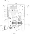
- an embodiment provides a control box 100, including an air supply system 1 used for supplying air to a water pool body (not shown).
- a first chamber 2 is arranged in the control box 100, and accommodates control components (not shown), and the control components are used for controlling the operation of the air supply system 1 and/or other systems (such as a water circulation system).
- the air supply system 1 includes:
- an air path is as shown in an arrow direction of Fig. 2 : a, air is suctioned from the first chamber 2 to the air inlet 111a in the housing 111; b, the air flows from the air inlet 111a of the housing 111 to an air pumping end of the air pump 112; c, after flowing out of an air exhaust end of the air pump 112, the air flows to the air outlet 111b of the housing 111; and d, the air flows from the air outlet 111b of the housing 111 into the pipeline of the valve part 12, and finally the air is supplied to the water pool body.
- the air pump 112 suctions air from the first chamber 2 instead of directly suctioning air from the outside of the control box 100 as in the prior art. Therefore, when the air pump 112 works, air in the first chamber can be suctioned to the outside of a cabinet body of the control box 100 through the air supply system 1, so that circulation and renewal of air in the first chamber 2 can be realized, thereby avoiding the accumulation of humid air. Therefore, according to the control box provided by the embodiment, the first chamber has a dry working environment, so that the service life of the control components accommodated in the first chamber can be prolonged.
- an air filter 113 is arranged at the air inlet 111a of the housing 111, and in the embodiment, the air filter 113 is sponge.
- the air filter may also be a filter membrane or the like, as long as it can play the role of filtering air.
- the air suction part 11 is adjacent to the first chamber 2 in a horizontal direction.
- the first chamber 2 is arranged around the air suction part 11, through the arrangement, an air flow path can be shortened, the air pumping efficiency of the air pump 112 from the first chamber 2 can be improved, and the volume of the control box can be reduced.
- the air pump 112 is a product which can be directly purchased and/or customized, specifically, the air pump 112 includes a motor and a fan driven by the motor, and an enclosure is arranged outside the fan.
- the air pump 112 one end of the enclosure of the fan has a larger outer diameter, and one end of the motor has a smaller outer diameter.
- the air pump 112 can suction air from one end of the fan to one end of the motor.
- the air pump is arranged in an upright mode in the control box, that is, one end of the fan is located below, and one end of the motor is located above.
- the applicant breaks through the conventional arrangement mode, the air pump 112 is arranged in the control box 100 in an inverted mode, and through the arrangement, at least the following technical effects are achieved:
- the mounting structure of the air pump 112 refers to a shoulder part 115 and a bearing part 114 arranged on an inner wall of the housing 111, wherein the bearing part 114 is arranged below the air pump 112 and used for supporting the weight of the air pump 112; the shoulder part 115 is located above the bearing part 114 and used for providing radial support for the air pump 112.
- the bearing part 114 is a tray arranged on a bottom wall of the housing 111
- the shoulder part 115 is a step arranged on a side wall of the housing 111, and through the arrangement, the mounting structure of the air pump 112 can be simplified maximally.
- the air pump 112 is arranged in an inverted mode, and the air pumping opening of the air pump 112 faces upwards, the air pumping opening of the air pump 112 can conveniently communicate with the first chamber 2.
- the air inlet 111a is formed in a top wall of the housing 111, and the air pumping end of the air pump 112 is opposite to the air inlet 11 1a, so that the air pumping opening of the air pump 112 can communicate with the first chamber 2.
- air holes 21 are formed in a bottom wall of the first chamber 2, air outside the control box 100 flows into the first chamber 2 through the air holes 21, and therefore, an air flow direction of the first chamber 2 is as shown in the arrow direction in Fig. 2 .
- the air holes 21 of the control box 100 are formed in the bottom wall of the first chamber 2, so that the presence of air flowing dead angles in the first chamber 2 can be avoided, and also the appearance of the control box 100 can be kept complete.
- the air outlet 111b of the housing 111 is located in the bottom wall of the housing 111, the valve part 12 is located below the housing 111, and the air intake port 124 of the valve part 12 is in butt joint with the air outlet 111b of the housing 111.
- the air suction part 11 and the valve part 12 are arranged in an up-down direction, the valve part 12 is located below the air suction part 11, and through the arrangement, the control box has a compact structure.
- the air outlet 111b of the housing 111 is adjacent to one side wall of the control box 100, so that the structure of the control box 100 can be further simplified.
- a water pool is a massage water pool
- the air supply system 1 of the control box 100 is used for supplying air to a water pool body of the massage water pool.
- the air supply system 1 not only can inflate the water pool body and also can spray bubbles into the water pool body so as to provide water for massaging.
- the air supply port 125 at least includes a first air supply port 125a and a second air supply port 125b, wherein the first air supply port 125a is used for spraying air bubbles into the water pool body of the massage water pool, and the second air supply port 125b is used for inflating the water pool body.
- the valve part 12 includes a first pipeline 121, a second pipeline 122, and a third pipeline 123, wherein the air intake port 124 is formed in the first pipeline 121, the first air supply port 125a is formed in the second pipeline 122, and the second air supply port 125b is formed in the third pipeline 123.
- the center lines (including a center line of the first pipeline 121, the center line of the second pipeline 122 and the center line of the third pipeline 123) of the pipelines and the center line of the air pump 112 are located in the same vertical plane.
- the center line of the first pipeline 121 extends in a vertical direction
- the center line of the second pipeline 122 and the center line of the third pipeline 123 extend in the horizontal direction respectively.
- the valve part is a check valve, which can guarantee the unidirectional flowing of air in the first pipeline 121, the second pipeline 122 and the third pipeline 123, and prevent water in the water pool body from flowing back into the air supply system 1.
- a water circulation pipeline is further arranged in the first chamber 2 of the control box 100, and a heating device is arranged on a path of the water circulation pipeline and can heat water in the water pool body.
- the water circulation pipeline includes an inlet and an outlet which are connected with the water pool body, and water in the water pool body flows to the water circulation pipeline from the inlet, is heated by the heating device and then flows back to the water pool body from the outlet, so that the water in the water pool body is maintained at a proper temperature.
- the air pump 112 can suction air in the first chamber 2, even if the water circulation pipeline is arranged in the first chamber 2, air in the first chamber 2 can be kept dry.
- An embodiment of the present invention further provides a massage water pool, including a water pool body, and the control box 100 provided by any one of the above embodiments.
- the air supply port 125 of the air supply system 1 of the control box 100 is connected with the water pool body.
- the air pump 112 of the air supply system 1 is started, the water pool body can be inflated and/or bubbles can be sprayed into the water pool body.
Landscapes
- Health & Medical Sciences (AREA)
- Public Health (AREA)
- Architecture (AREA)
- Engineering & Computer Science (AREA)
- Rehabilitation Therapy (AREA)
- Epidemiology (AREA)
- Pain & Pain Management (AREA)
- Physical Education & Sports Medicine (AREA)
- Life Sciences & Earth Sciences (AREA)
- Animal Behavior & Ethology (AREA)
- General Health & Medical Sciences (AREA)
- Veterinary Medicine (AREA)
- Structural Engineering (AREA)
- Civil Engineering (AREA)
- Massaging Devices (AREA)
Claims (12)
- Boîtier de commande (100), ledit boîtier de commande (100) étant pourvu à l'intérieur d'une première chambre (2) qui est utilisée pour loger un composant de commande, et étant en outre pourvu à l'intérieur d'un système d'alimentation en air (1) qui est utilisé pour alimenter en air un corps de bassin d'eau et comprend :une partie d'aspiration d'air (11), pourvue d'un logement (111) qui est pourvu d'une entrée d'air (111a) et d'une sortie d'air (111b), dans lequel l'entrée d'air (111a) communique avec la première chambre (2) ; la partie d'aspiration d'air (11) incluant en outre une pompe à air (112) agencée dans le logement (111), dans lequel l'air dans la première chambre (2) peut être aspiré dans le logement (111) à travers l'entrée d'air (111a) lorsque la pompe à air (112) est démarrée ; etune partie de vanne (12), pourvue d'une canalisation (121, 122, 123), dans lequel la canalisation (121, 122, 123) est pourvue d'un orifice d'admission d'air (124) et d'un orifice d'alimentation en air (125), l'orifice d'admission d'air (124) communique avec la sortie d'air (111b) du logement (111), et l'orifice d'alimentation en air (125) est utilisé pour communiquer avec le corps de bassin d'eau, et lorsque la partie de vanne (12) est démarrée, l'air aspiré dans le logement (111) peut s'écouler dans le corps de bassin d'eau le long de la canalisation (121, 122, 123), caractériséen ce que la pompe à air (112) est agencée dans un mode inversé, l'entrée d'air (111a) est formée dans une paroi haute du logement (111), et une extrémité de pompage d'air de la pompe à air (112) est agencée à l'opposé de l'entrée d'air (111a).
- Boîtier de commande (100) selon la revendication 1, caractérisé en ce que la partie d'aspiration d'air (11) est adjacente à la première chambre (2) dans une direction horizontale.
- Boîtier de commande (100) selon la revendication 1, caractérisé en ce qu'une partie de roulement (114) et une partie d'épaulement (115) située au-dessus de la partie de roulement (114) sont agencées sur une paroi interne du logement (111), et la pompe à air (112) est fixée dans le logement (111) à travers la partie d'épaulement (115) et la partie de roulement (114).
- Boîtier de commande (100) selon la revendication 1, caractérisé en ce que des trous d'air (21) sont formés dans une paroi basse de la première chambre (2).
- Boîtier de commande (100) selon la revendication 1, caractérisé en ce que la sortie d'air (111b) du logement (111) est située dans une paroi basse du logement (111), et la sortie d'air (111b) du logement (111) est adjacente à une paroi de côté du boîtier de commande (100).
- Boîtier de commande (100) selon la revendication 5, caractérisé en ce que la partie de vanne (12) est située en dessous du logement (111).
- Boîtier de commande (100) selon la revendication 1, caractérisé en ce que le boîtier de commande (100) est convenable pour être utilisé pour un bassin d'eau de massage ; et
l'orifice d'alimentation en air (125) comprend au moins un premier orifice d'alimentation en air (125a) et un second orifice d'alimentation en air (125b), dans lequel le premier orifice d'alimentation en air (125a) est adapté pour être utilisé pour pulvériser des bulles dans un corps de bassin d'eau du bassin d'eau de massage, et le second orifice d'alimentation en air (125b) est adapté pour être utilisé pour gonfler le corps de bassin d'eau. - Boîtier de commande (100) selon la revendication 7, caractérisé en ce que l'axe central de la canalisation et l'axe central de la pompe à air (112) sont situés dans le même plan vertical.
- Boîtier de commande (100) selon la revendication 7, caractérisé en ce que la partie de vanne (12) est un clapet antiretour.
- Boîtier de commande (100) selon la revendication 1, caractérisé en ce qu'un filtre à air (113) est agencé au niveau de l'entrée d'air (111a).
- Boîtier de commande (100) selon la revendication 1, caractérisé en ce qu'une canalisation de circulation d'eau est en outre agencée dans la première chambre (2) du boîtier de commande (100).
- Bassin d'eau de massage, caractérisé en ce qu'il comprend le boîtier de commande (100) selon l'une quelconque des revendications 1 à 11.
Applications Claiming Priority (2)
| Application Number | Priority Date | Filing Date | Title |
|---|---|---|---|
| CN201910827756.6A CN112443180A (zh) | 2019-09-03 | 2019-09-03 | 一种控制箱以及按摩水池 |
| PCT/CN2020/109124 WO2021042966A1 (fr) | 2019-09-03 | 2020-08-14 | Boîte de commande et spa |
Publications (3)
| Publication Number | Publication Date |
|---|---|
| EP4006268A1 EP4006268A1 (fr) | 2022-06-01 |
| EP4006268A4 EP4006268A4 (fr) | 2022-12-21 |
| EP4006268B1 true EP4006268B1 (fr) | 2024-05-08 |
Family
ID=74734755
Family Applications (1)
| Application Number | Title | Priority Date | Filing Date |
|---|---|---|---|
| EP20861192.1A Active EP4006268B1 (fr) | 2019-09-03 | 2020-08-14 | Boîte de commande et spa |
Country Status (4)
| Country | Link |
|---|---|
| US (1) | US12370123B2 (fr) |
| EP (1) | EP4006268B1 (fr) |
| CN (1) | CN112443180A (fr) |
| WO (1) | WO2021042966A1 (fr) |
Families Citing this family (7)
| Publication number | Priority date | Publication date | Assignee | Title |
|---|---|---|---|---|
| CN112443181B (zh) * | 2019-09-03 | 2024-12-24 | 东辉休闲运动用品(上海)有限公司 | 水循环管路、控制箱以及按摩水池 |
| WO2022070045A1 (fr) | 2020-09-29 | 2022-04-07 | Intex Industries Xiamen Co. Ltd. | Unité de passage d'air, système de passage d'air, corps de bassin et bassin de massage |
| CN216009650U (zh) * | 2021-07-15 | 2022-03-11 | 明达实业(厦门)有限公司 | 按摩水池接气管路装置、按摩水池池体及按摩水池 |
| EP4370085B1 (fr) * | 2021-07-15 | 2025-11-12 | Intex Marketing Ltd. | Un système d'air d'une piscine de massage, comprenant une pompe à air et une unité d'air |
| CN216042922U (zh) | 2021-07-15 | 2022-03-15 | 明达实业(厦门)有限公司 | Spa水池带补偿功能的气路结构及spa水池 |
| CN216045610U (zh) | 2021-07-15 | 2022-03-15 | 明达实业(厦门)有限公司 | 带控制阀的按摩水池气路结构 |
| EP4385484B1 (fr) * | 2022-12-12 | 2025-07-09 | Bestway Inflatables & Material Corp. | Piscine gonflable de massage |
Family Cites Families (17)
| Publication number | Priority date | Publication date | Assignee | Title |
|---|---|---|---|---|
| US20060207018A1 (en) * | 2005-03-18 | 2006-09-21 | Mordechai Lev | Fan assembly for a bath therapy apparatus |
| CN201175295Y (zh) * | 2008-03-26 | 2009-01-07 | 上海美欣塑胶制品有限公司 | 可移式泡泡按摩充气浴池 |
| JP5764377B2 (ja) | 2011-04-20 | 2015-08-19 | アイシン精機株式会社 | 泡入浴システム |
| US10357427B1 (en) | 2019-02-14 | 2019-07-23 | Kevin Le | Air massage device for pedicure spa and method |
| CN203634453U (zh) | 2013-12-30 | 2014-06-11 | 明达实业(厦门)有限公司 | 一种按摩水池系统 |
| EP3225764B1 (fr) * | 2013-07-18 | 2020-09-09 | Intex Marketing Ltd. | Spa gonflable |
| CN203962354U (zh) | 2014-07-07 | 2014-11-26 | 奉化市盛强晨亿机械有限公司 | 塑壳气泵 |
| US10245210B2 (en) * | 2016-04-08 | 2019-04-02 | J&A USA Inc. | Whirlpool spa motor pump of whirlpool massage bathtub |
| CN207082751U (zh) * | 2017-05-24 | 2018-03-09 | 天津雷玉科技有限公司 | 一种能够散热防潮的高低压开关柜 |
| CN208319114U (zh) * | 2017-08-29 | 2019-01-04 | 东辉休闲运动用品(上海)有限公司 | 一种按摩浴缸的电控箱 |
| CN207260666U (zh) * | 2017-08-29 | 2018-04-20 | 东辉休闲运动用品(上海)有限公司 | 一种具有可内外置控制箱的按摩水池 |
| CN109424221A (zh) * | 2017-08-29 | 2019-03-05 | 东辉休闲运动用品(上海)有限公司 | 一种按摩水池空气供应系统及其控制方法 |
| CN207948003U (zh) * | 2018-02-07 | 2018-10-09 | 广州众通电子科技有限公司 | 一种节能式水闸现地控制柜 |
| CN208845793U (zh) * | 2018-08-23 | 2019-05-10 | 东辉休闲运动用品(上海)有限公司 | 一种单向阀及按摩水池空气供应系统 |
| CN110043078A (zh) * | 2019-04-23 | 2019-07-23 | 深圳市雷凌广通技术研发有限公司 | 一种具有防潮功能的环保型5g通讯基站 |
| CN211058396U (zh) * | 2019-09-03 | 2020-07-21 | 东辉休闲运动用品(上海)有限公司 | 一种控制箱以及按摩水池 |
| CN214806641U (zh) * | 2020-11-23 | 2021-11-23 | 广州斯帕蒂工程技术服务有限公司 | 一种防冻防潮的按摩水池 |
-
2019
- 2019-09-03 CN CN201910827756.6A patent/CN112443180A/zh active Pending
-
2020
- 2020-08-14 US US17/639,827 patent/US12370123B2/en active Active
- 2020-08-14 WO PCT/CN2020/109124 patent/WO2021042966A1/fr not_active Ceased
- 2020-08-14 EP EP20861192.1A patent/EP4006268B1/fr active Active
Also Published As
| Publication number | Publication date |
|---|---|
| US12370123B2 (en) | 2025-07-29 |
| EP4006268A1 (fr) | 2022-06-01 |
| EP4006268A4 (fr) | 2022-12-21 |
| US20220241148A1 (en) | 2022-08-04 |
| CN112443180A (zh) | 2021-03-05 |
| WO2021042966A1 (fr) | 2021-03-11 |
Similar Documents
| Publication | Publication Date | Title |
|---|---|---|
| EP4006268B1 (fr) | Boîte de commande et spa | |
| KR102220214B1 (ko) | 공기 청정기 | |
| KR101677477B1 (ko) | 팬 조립체 | |
| KR101769817B1 (ko) | 가습청정장치 | |
| CN103939986B (zh) | 立式空调器室内机 | |
| US10151499B2 (en) | Apparatus for both humidification and air cleaning | |
| JP2021167714A (ja) | 加湿清浄装置 | |
| CN102215986A (zh) | 高压清洁设备 | |
| JP7069009B2 (ja) | 加湿清浄装置 | |
| JP2021085656A (ja) | 加湿器 | |
| KR20170051108A (ko) | 가습청정장치 | |
| CN102865214A (zh) | 无叶风扇装置 | |
| KR101880484B1 (ko) | 가습청정장치 | |
| CN203857555U (zh) | 空调器室内机 | |
| US6681414B1 (en) | Jet flow control for hydrotherapy spa | |
| KR20170040163A (ko) | 청정기 | |
| CN103939988A (zh) | 空调器室内机 | |
| CN211058396U (zh) | 一种控制箱以及按摩水池 | |
| US20240361030A1 (en) | Humidifier | |
| KR20170040162A (ko) | 가습청정기 | |
| CN203857551U (zh) | 空调器室内机 | |
| KR101432131B1 (ko) | 온도조절 및 산소공급이 가능한 수족관 | |
| RU2091180C1 (ru) | Фонтан-каскад | |
| KR20170040161A (ko) | 가습청정기 | |
| KR20090057520A (ko) | 산소발생기 |
Legal Events
| Date | Code | Title | Description |
|---|---|---|---|
| STAA | Information on the status of an ep patent application or granted ep patent |
Free format text: STATUS: THE INTERNATIONAL PUBLICATION HAS BEEN MADE |
|
| PUAI | Public reference made under article 153(3) epc to a published international application that has entered the european phase |
Free format text: ORIGINAL CODE: 0009012 |
|
| STAA | Information on the status of an ep patent application or granted ep patent |
Free format text: STATUS: REQUEST FOR EXAMINATION WAS MADE |
|
| 17P | Request for examination filed |
Effective date: 20220222 |
|
| AK | Designated contracting states |
Kind code of ref document: A1 Designated state(s): AL AT BE BG CH CY CZ DE DK EE ES FI FR GB GR HR HU IE IS IT LI LT LU LV MC MK MT NL NO PL PT RO RS SE SI SK SM TR |
|
| DAV | Request for validation of the european patent (deleted) | ||
| DAX | Request for extension of the european patent (deleted) | ||
| A4 | Supplementary search report drawn up and despatched |
Effective date: 20221117 |
|
| RIC1 | Information provided on ipc code assigned before grant |
Ipc: A61H 33/02 20060101ALI20221111BHEP Ipc: E04H 4/14 20060101ALI20221111BHEP Ipc: E04H 4/00 20060101AFI20221111BHEP |
|
| RIN1 | Information on inventor provided before grant (corrected) |
Inventor name: WANG, ZHIYUE |
|
| REG | Reference to a national code |
Ref country code: DE Ref legal event code: R079 Ref country code: DE Ref legal event code: R079 Ref document number: 602020030758 Country of ref document: DE Free format text: PREVIOUS MAIN CLASS: E04H0004000000 Ipc: A61H0033020000 |
|
| GRAP | Despatch of communication of intention to grant a patent |
Free format text: ORIGINAL CODE: EPIDOSNIGR1 |
|
| STAA | Information on the status of an ep patent application or granted ep patent |
Free format text: STATUS: GRANT OF PATENT IS INTENDED |
|
| RIC1 | Information provided on ipc code assigned before grant |
Ipc: E04H 4/00 20060101ALI20240118BHEP Ipc: A61H 33/00 20060101ALI20240118BHEP Ipc: A61H 33/02 20060101AFI20240118BHEP |
|
| INTG | Intention to grant announced |
Effective date: 20240131 |
|
| GRAS | Grant fee paid |
Free format text: ORIGINAL CODE: EPIDOSNIGR3 |
|
| GRAA | (expected) grant |
Free format text: ORIGINAL CODE: 0009210 |
|
| STAA | Information on the status of an ep patent application or granted ep patent |
Free format text: STATUS: THE PATENT HAS BEEN GRANTED |
|
| P01 | Opt-out of the competence of the unified patent court (upc) registered |
Effective date: 20240301 |
|
| RAP3 | Party data changed (applicant data changed or rights of an application transferred) |
Owner name: ORIENTAL RECREATIONAL PRODUCTS (SHANGHAI) CO., LTD |
|
| RIN1 | Information on inventor provided before grant (corrected) |
Inventor name: WANG, ZHIYUE |
|
| AK | Designated contracting states |
Kind code of ref document: B1 Designated state(s): AL AT BE BG CH CY CZ DE DK EE ES FI FR GB GR HR HU IE IS IT LI LT LU LV MC MK MT NL NO PL PT RO RS SE SI SK SM TR |
|
| REG | Reference to a national code |
Ref country code: GB Ref legal event code: FG4D |
|
| REG | Reference to a national code |
Ref country code: CH Ref legal event code: EP |
|
| REG | Reference to a national code |
Ref country code: DE Ref legal event code: R096 Ref document number: 602020030758 Country of ref document: DE |
|
| REG | Reference to a national code |
Ref country code: IE Ref legal event code: FG4D |
|
| REG | Reference to a national code |
Ref country code: SE Ref legal event code: TRGR |
|
| REG | Reference to a national code |
Ref country code: LT Ref legal event code: MG9D |
|
| REG | Reference to a national code |
Ref country code: NL Ref legal event code: MP Effective date: 20240508 |
|
| PG25 | Lapsed in a contracting state [announced via postgrant information from national office to epo] |
Ref country code: IS Free format text: LAPSE BECAUSE OF FAILURE TO SUBMIT A TRANSLATION OF THE DESCRIPTION OR TO PAY THE FEE WITHIN THE PRESCRIBED TIME-LIMIT Effective date: 20240908 |
|
| PG25 | Lapsed in a contracting state [announced via postgrant information from national office to epo] |
Ref country code: BG Free format text: LAPSE BECAUSE OF FAILURE TO SUBMIT A TRANSLATION OF THE DESCRIPTION OR TO PAY THE FEE WITHIN THE PRESCRIBED TIME-LIMIT Effective date: 20240508 |
|
| PG25 | Lapsed in a contracting state [announced via postgrant information from national office to epo] |
Ref country code: FI Free format text: LAPSE BECAUSE OF FAILURE TO SUBMIT A TRANSLATION OF THE DESCRIPTION OR TO PAY THE FEE WITHIN THE PRESCRIBED TIME-LIMIT Effective date: 20240508 Ref country code: HR Free format text: LAPSE BECAUSE OF FAILURE TO SUBMIT A TRANSLATION OF THE DESCRIPTION OR TO PAY THE FEE WITHIN THE PRESCRIBED TIME-LIMIT Effective date: 20240508 |
|
| PG25 | Lapsed in a contracting state [announced via postgrant information from national office to epo] |
Ref country code: GR Free format text: LAPSE BECAUSE OF FAILURE TO SUBMIT A TRANSLATION OF THE DESCRIPTION OR TO PAY THE FEE WITHIN THE PRESCRIBED TIME-LIMIT Effective date: 20240809 |
|
| PG25 | Lapsed in a contracting state [announced via postgrant information from national office to epo] |
Ref country code: PT Free format text: LAPSE BECAUSE OF FAILURE TO SUBMIT A TRANSLATION OF THE DESCRIPTION OR TO PAY THE FEE WITHIN THE PRESCRIBED TIME-LIMIT Effective date: 20240909 |
|
| REG | Reference to a national code |
Ref country code: AT Ref legal event code: MK05 Ref document number: 1684427 Country of ref document: AT Kind code of ref document: T Effective date: 20240508 |
|
| PG25 | Lapsed in a contracting state [announced via postgrant information from national office to epo] |
Ref country code: NL Free format text: LAPSE BECAUSE OF FAILURE TO SUBMIT A TRANSLATION OF THE DESCRIPTION OR TO PAY THE FEE WITHIN THE PRESCRIBED TIME-LIMIT Effective date: 20240508 |
|
| PG25 | Lapsed in a contracting state [announced via postgrant information from national office to epo] |
Ref country code: ES Free format text: LAPSE BECAUSE OF FAILURE TO SUBMIT A TRANSLATION OF THE DESCRIPTION OR TO PAY THE FEE WITHIN THE PRESCRIBED TIME-LIMIT Effective date: 20240508 |
|
| PG25 | Lapsed in a contracting state [announced via postgrant information from national office to epo] |
Ref country code: AT Free format text: LAPSE BECAUSE OF FAILURE TO SUBMIT A TRANSLATION OF THE DESCRIPTION OR TO PAY THE FEE WITHIN THE PRESCRIBED TIME-LIMIT Effective date: 20240508 |
|
| PG25 | Lapsed in a contracting state [announced via postgrant information from national office to epo] |
Ref country code: PL Free format text: LAPSE BECAUSE OF FAILURE TO SUBMIT A TRANSLATION OF THE DESCRIPTION OR TO PAY THE FEE WITHIN THE PRESCRIBED TIME-LIMIT Effective date: 20240508 |
|
| PG25 | Lapsed in a contracting state [announced via postgrant information from national office to epo] |
Ref country code: LV Free format text: LAPSE BECAUSE OF FAILURE TO SUBMIT A TRANSLATION OF THE DESCRIPTION OR TO PAY THE FEE WITHIN THE PRESCRIBED TIME-LIMIT Effective date: 20240508 |
|
| PG25 | Lapsed in a contracting state [announced via postgrant information from national office to epo] |
Ref country code: PT Free format text: LAPSE BECAUSE OF FAILURE TO SUBMIT A TRANSLATION OF THE DESCRIPTION OR TO PAY THE FEE WITHIN THE PRESCRIBED TIME-LIMIT Effective date: 20240909 Ref country code: PL Free format text: LAPSE BECAUSE OF FAILURE TO SUBMIT A TRANSLATION OF THE DESCRIPTION OR TO PAY THE FEE WITHIN THE PRESCRIBED TIME-LIMIT Effective date: 20240508 Ref country code: NL Free format text: LAPSE BECAUSE OF FAILURE TO SUBMIT A TRANSLATION OF THE DESCRIPTION OR TO PAY THE FEE WITHIN THE PRESCRIBED TIME-LIMIT Effective date: 20240508 Ref country code: LV Free format text: LAPSE BECAUSE OF FAILURE TO SUBMIT A TRANSLATION OF THE DESCRIPTION OR TO PAY THE FEE WITHIN THE PRESCRIBED TIME-LIMIT Effective date: 20240508 Ref country code: IS Free format text: LAPSE BECAUSE OF FAILURE TO SUBMIT A TRANSLATION OF THE DESCRIPTION OR TO PAY THE FEE WITHIN THE PRESCRIBED TIME-LIMIT Effective date: 20240908 Ref country code: HR Free format text: LAPSE BECAUSE OF FAILURE TO SUBMIT A TRANSLATION OF THE DESCRIPTION OR TO PAY THE FEE WITHIN THE PRESCRIBED TIME-LIMIT Effective date: 20240508 Ref country code: GR Free format text: LAPSE BECAUSE OF FAILURE TO SUBMIT A TRANSLATION OF THE DESCRIPTION OR TO PAY THE FEE WITHIN THE PRESCRIBED TIME-LIMIT Effective date: 20240809 Ref country code: FI Free format text: LAPSE BECAUSE OF FAILURE TO SUBMIT A TRANSLATION OF THE DESCRIPTION OR TO PAY THE FEE WITHIN THE PRESCRIBED TIME-LIMIT Effective date: 20240508 Ref country code: ES Free format text: LAPSE BECAUSE OF FAILURE TO SUBMIT A TRANSLATION OF THE DESCRIPTION OR TO PAY THE FEE WITHIN THE PRESCRIBED TIME-LIMIT Effective date: 20240508 Ref country code: BG Free format text: LAPSE BECAUSE OF FAILURE TO SUBMIT A TRANSLATION OF THE DESCRIPTION OR TO PAY THE FEE WITHIN THE PRESCRIBED TIME-LIMIT Effective date: 20240508 Ref country code: AT Free format text: LAPSE BECAUSE OF FAILURE TO SUBMIT A TRANSLATION OF THE DESCRIPTION OR TO PAY THE FEE WITHIN THE PRESCRIBED TIME-LIMIT Effective date: 20240508 Ref country code: RS Free format text: LAPSE BECAUSE OF FAILURE TO SUBMIT A TRANSLATION OF THE DESCRIPTION OR TO PAY THE FEE WITHIN THE PRESCRIBED TIME-LIMIT Effective date: 20240808 |
|
| PG25 | Lapsed in a contracting state [announced via postgrant information from national office to epo] |
Ref country code: DK Free format text: LAPSE BECAUSE OF FAILURE TO SUBMIT A TRANSLATION OF THE DESCRIPTION OR TO PAY THE FEE WITHIN THE PRESCRIBED TIME-LIMIT Effective date: 20240508 |
|
| PG25 | Lapsed in a contracting state [announced via postgrant information from national office to epo] |
Ref country code: EE Free format text: LAPSE BECAUSE OF FAILURE TO SUBMIT A TRANSLATION OF THE DESCRIPTION OR TO PAY THE FEE WITHIN THE PRESCRIBED TIME-LIMIT Effective date: 20240508 |
|
| PG25 | Lapsed in a contracting state [announced via postgrant information from national office to epo] |
Ref country code: CZ Free format text: LAPSE BECAUSE OF FAILURE TO SUBMIT A TRANSLATION OF THE DESCRIPTION OR TO PAY THE FEE WITHIN THE PRESCRIBED TIME-LIMIT Effective date: 20240508 |
|
| PG25 | Lapsed in a contracting state [announced via postgrant information from national office to epo] |
Ref country code: RO Free format text: LAPSE BECAUSE OF FAILURE TO SUBMIT A TRANSLATION OF THE DESCRIPTION OR TO PAY THE FEE WITHIN THE PRESCRIBED TIME-LIMIT Effective date: 20240508 Ref country code: SK Free format text: LAPSE BECAUSE OF FAILURE TO SUBMIT A TRANSLATION OF THE DESCRIPTION OR TO PAY THE FEE WITHIN THE PRESCRIBED TIME-LIMIT Effective date: 20240508 |
|
| PG25 | Lapsed in a contracting state [announced via postgrant information from national office to epo] |
Ref country code: SM Free format text: LAPSE BECAUSE OF FAILURE TO SUBMIT A TRANSLATION OF THE DESCRIPTION OR TO PAY THE FEE WITHIN THE PRESCRIBED TIME-LIMIT Effective date: 20240508 |
|
| PG25 | Lapsed in a contracting state [announced via postgrant information from national office to epo] |
Ref country code: SM Free format text: LAPSE BECAUSE OF FAILURE TO SUBMIT A TRANSLATION OF THE DESCRIPTION OR TO PAY THE FEE WITHIN THE PRESCRIBED TIME-LIMIT Effective date: 20240508 Ref country code: SK Free format text: LAPSE BECAUSE OF FAILURE TO SUBMIT A TRANSLATION OF THE DESCRIPTION OR TO PAY THE FEE WITHIN THE PRESCRIBED TIME-LIMIT Effective date: 20240508 Ref country code: RO Free format text: LAPSE BECAUSE OF FAILURE TO SUBMIT A TRANSLATION OF THE DESCRIPTION OR TO PAY THE FEE WITHIN THE PRESCRIBED TIME-LIMIT Effective date: 20240508 Ref country code: EE Free format text: LAPSE BECAUSE OF FAILURE TO SUBMIT A TRANSLATION OF THE DESCRIPTION OR TO PAY THE FEE WITHIN THE PRESCRIBED TIME-LIMIT Effective date: 20240508 Ref country code: DK Free format text: LAPSE BECAUSE OF FAILURE TO SUBMIT A TRANSLATION OF THE DESCRIPTION OR TO PAY THE FEE WITHIN THE PRESCRIBED TIME-LIMIT Effective date: 20240508 Ref country code: CZ Free format text: LAPSE BECAUSE OF FAILURE TO SUBMIT A TRANSLATION OF THE DESCRIPTION OR TO PAY THE FEE WITHIN THE PRESCRIBED TIME-LIMIT Effective date: 20240508 |
|
| PG25 | Lapsed in a contracting state [announced via postgrant information from national office to epo] |
Ref country code: IT Free format text: LAPSE BECAUSE OF FAILURE TO SUBMIT A TRANSLATION OF THE DESCRIPTION OR TO PAY THE FEE WITHIN THE PRESCRIBED TIME-LIMIT Effective date: 20240508 |
|
| REG | Reference to a national code |
Ref country code: DE Ref legal event code: R097 Ref document number: 602020030758 Country of ref document: DE |
|
| PLBE | No opposition filed within time limit |
Free format text: ORIGINAL CODE: 0009261 |
|
| STAA | Information on the status of an ep patent application or granted ep patent |
Free format text: STATUS: NO OPPOSITION FILED WITHIN TIME LIMIT |
|
| REG | Reference to a national code |
Ref country code: CH Ref legal event code: PL |
|
| 26N | No opposition filed |
Effective date: 20250211 |
|
| PG25 | Lapsed in a contracting state [announced via postgrant information from national office to epo] |
Ref country code: LU Free format text: LAPSE BECAUSE OF NON-PAYMENT OF DUE FEES Effective date: 20240814 |
|
| PG25 | Lapsed in a contracting state [announced via postgrant information from national office to epo] |
Ref country code: SI Free format text: LAPSE BECAUSE OF FAILURE TO SUBMIT A TRANSLATION OF THE DESCRIPTION OR TO PAY THE FEE WITHIN THE PRESCRIBED TIME-LIMIT Effective date: 20240508 Ref country code: MC Free format text: LAPSE BECAUSE OF FAILURE TO SUBMIT A TRANSLATION OF THE DESCRIPTION OR TO PAY THE FEE WITHIN THE PRESCRIBED TIME-LIMIT Effective date: 20240508 Ref country code: CH Free format text: LAPSE BECAUSE OF NON-PAYMENT OF DUE FEES Effective date: 20240831 |
|
| REG | Reference to a national code |
Ref country code: BE Ref legal event code: MM Effective date: 20240831 |
|
| PG25 | Lapsed in a contracting state [announced via postgrant information from national office to epo] |
Ref country code: BE Free format text: LAPSE BECAUSE OF NON-PAYMENT OF DUE FEES Effective date: 20240831 |
|
| PG25 | Lapsed in a contracting state [announced via postgrant information from national office to epo] |
Ref country code: IE Free format text: LAPSE BECAUSE OF NON-PAYMENT OF DUE FEES Effective date: 20240814 |
|
| PGFP | Annual fee paid to national office [announced via postgrant information from national office to epo] |
Ref country code: DE Payment date: 20250812 Year of fee payment: 6 |
|
| PGFP | Annual fee paid to national office [announced via postgrant information from national office to epo] |
Ref country code: NO Payment date: 20250728 Year of fee payment: 6 |
|
| PGFP | Annual fee paid to national office [announced via postgrant information from national office to epo] |
Ref country code: GB Payment date: 20250826 Year of fee payment: 6 |
|
| PGFP | Annual fee paid to national office [announced via postgrant information from national office to epo] |
Ref country code: FR Payment date: 20250828 Year of fee payment: 6 |
|
| PGFP | Annual fee paid to national office [announced via postgrant information from national office to epo] |
Ref country code: SE Payment date: 20250826 Year of fee payment: 6 |
|
| PG25 | Lapsed in a contracting state [announced via postgrant information from national office to epo] |
Ref country code: CY Free format text: LAPSE BECAUSE OF FAILURE TO SUBMIT A TRANSLATION OF THE DESCRIPTION OR TO PAY THE FEE WITHIN THE PRESCRIBED TIME-LIMIT; INVALID AB INITIO Effective date: 20200814 |
|
| PG25 | Lapsed in a contracting state [announced via postgrant information from national office to epo] |
Ref country code: HU Free format text: LAPSE BECAUSE OF FAILURE TO SUBMIT A TRANSLATION OF THE DESCRIPTION OR TO PAY THE FEE WITHIN THE PRESCRIBED TIME-LIMIT; INVALID AB INITIO Effective date: 20200814 |