EP4006269B1 - Lager-/parkvorrichtung für fahrzeuge - Google Patents
Lager-/parkvorrichtung für fahrzeuge Download PDFInfo
- Publication number
- EP4006269B1 EP4006269B1 EP21208309.1A EP21208309A EP4006269B1 EP 4006269 B1 EP4006269 B1 EP 4006269B1 EP 21208309 A EP21208309 A EP 21208309A EP 4006269 B1 EP4006269 B1 EP 4006269B1
- Authority
- EP
- European Patent Office
- Prior art keywords
- parking
- drag
- drive
- gondolas
- electrical
- Prior art date
- Legal status (The legal status is an assumption and is not a legal conclusion. Google has not performed a legal analysis and makes no representation as to the accuracy of the status listed.)
- Active
Links
Images


Classifications
-
- E—FIXED CONSTRUCTIONS
- E04—BUILDING
- E04H—BUILDINGS OR LIKE STRUCTURES FOR PARTICULAR PURPOSES; SWIMMING OR SPLASH BATHS OR POOLS; MASTS; FENCING; TENTS OR CANOPIES, IN GENERAL
- E04H6/00—Buildings for parking cars, rolling-stock, aircraft, vessels or like vehicles, e.g. garages
- E04H6/08—Garages for many vehicles
- E04H6/12—Garages for many vehicles with mechanical means for shifting or lifting vehicles
- E04H6/14—Garages for many vehicles with mechanical means for shifting or lifting vehicles with endless conveyor chains having load-carrying parts moving vertically, e.g. paternoster lifts also similar transport in which cells are continuously mechanically linked together
-
- B—PERFORMING OPERATIONS; TRANSPORTING
- B60—VEHICLES IN GENERAL
- B60L—PROPULSION OF ELECTRICALLY-PROPELLED VEHICLES; SUPPLYING ELECTRIC POWER FOR AUXILIARY EQUIPMENT OF ELECTRICALLY-PROPELLED VEHICLES; ELECTRODYNAMIC BRAKE SYSTEMS FOR VEHICLES IN GENERAL; MAGNETIC SUSPENSION OR LEVITATION FOR VEHICLES; MONITORING OPERATING VARIABLES OF ELECTRICALLY-PROPELLED VEHICLES; ELECTRIC SAFETY DEVICES FOR ELECTRICALLY-PROPELLED VEHICLES
- B60L53/00—Methods of charging batteries, specially adapted for electric vehicles; Charging stations or on-board charging equipment therefor; Exchange of energy storage elements in electric vehicles
- B60L53/30—Constructional details of charging stations
-
- B—PERFORMING OPERATIONS; TRANSPORTING
- B60—VEHICLES IN GENERAL
- B60L—PROPULSION OF ELECTRICALLY-PROPELLED VEHICLES; SUPPLYING ELECTRIC POWER FOR AUXILIARY EQUIPMENT OF ELECTRICALLY-PROPELLED VEHICLES; ELECTRODYNAMIC BRAKE SYSTEMS FOR VEHICLES IN GENERAL; MAGNETIC SUSPENSION OR LEVITATION FOR VEHICLES; MONITORING OPERATING VARIABLES OF ELECTRICALLY-PROPELLED VEHICLES; ELECTRIC SAFETY DEVICES FOR ELECTRICALLY-PROPELLED VEHICLES
- B60L53/00—Methods of charging batteries, specially adapted for electric vehicles; Charging stations or on-board charging equipment therefor; Exchange of energy storage elements in electric vehicles
- B60L53/60—Monitoring or controlling charging stations
-
- H—ELECTRICITY
- H02—GENERATION; CONVERSION OR DISTRIBUTION OF ELECTRIC POWER
- H02G—INSTALLATION OF ELECTRIC CABLES OR LINES, OR OF COMBINED OPTICAL AND ELECTRIC CABLES OR LINES
- H02G11/00—Arrangements of electric cables or lines between relatively-movable parts
- H02G11/006—Arrangements of electric cables or lines between relatively-movable parts using extensible carrier for the cable, e.g. self-coiling spring
Definitions
- the invention relates to a storage/parking device, preferably for vehicles such as motor vehicles, bicycles, etc., in particular a vertical parking tower, with several parking gondolas that can be moved relative to a stationary base structure, further with a drive for the parking gondolas coupled to one another, and with at least one electrical supply unit, preferably an electrical connection unit, as well as an associated electrical connection line on at least one parking gondola, the respective parking gondola being movable between a loading position and a storage position or parking position that is offset vertically and/or horizontally.
- a storage/parking device preferably for vehicles such as motor vehicles, bicycles, etc., in particular a vertical parking tower, with several parking gondolas that can be moved relative to a stationary base structure, further with a drive for the parking gondolas coupled to one another, and with at least one electrical supply unit, preferably an electrical connection unit, as well as an associated electrical connection line on at least one parking gondola, the respective parking gondola
- Such storage/parking devices are also referred to as vertical parking towers, which work according to the paternoster principle.
- the parking gondolas move in a similar way to the cabins in a paternoster elevator, as is known, for example, for transporting people and has been used for decades.
- the individual parking gondolas are regularly moved in circulation using a circulation chain as a drive link and are attached to the relevant circulation chain or the several circulation chains.
- a circulation chain as a drive link
- the invention proposes in a generic storage/parking device that at least one flexible towing member, which can be moved together with the parking gondolas, is provided to guide the at least one electrical connecting cable.
- connection between the drive member and the flexible towing member takes place in such a way that floating drivers are interposed at this point. That is, one or more drivers are implemented between the flexible drive member and the flexible drag member. The drivers are also mounted in a floating manner, so they allow for relative play between the respective drive member on the one hand and the towing member on the other.
- the procedure is usually such that the towing link is connected to two fixed points on the basic structure.
- the two fixed points are usually found at the top of the basic structure.
- the procedure is usually such that the towing link is only guided over a deflection element that is rotatably mounted on the head side of the base frame.
- the drive member is guided via the deflection element, which is rotatably mounted on the base frame on both the head and foot sides.
- the towing link is guided from the two fixed points on the head side of the base frame only over the deflection element which is rotatably mounted on the head side of the base frame, the towing link can be positioned in front view on the deflection elements and thus the narrow side of the base frame between a right complete sling position and a left complete sling position and a central half loop position. This will be explained in more detail with reference to the exemplary embodiment.
- the drag link is generally provided and designed as a drag chain with U-shaped chain links.
- the deflection element is a double pinion for, on the one hand, a drive chain as a drive link and, on the other hand, the drag chain as a drag link.
- the design is further made such that the U-shaped chain links also accommodate at least one data line in addition to the at least one electrical connection line.
- the data line is usually connected to a control unit for data technology. In this way, load management can be implemented, which will be explained in more detail below. In addition, the control unit can thereby control each individual supply unit.
- the U-shaped chain links are equipped with separating bars to separate the individual cables from each other to guide the electrical connection cable as well as the data cable. In this way, perfect routing of the individual lines is guaranteed, especially in the event that several electrical connection cables are provided.
- the fact that the cables are fixed to the chain links by means of strain relief also contributes to this. This avoids any tension between, on the one hand, the respective chain link and consequently the drag chain and, on the other hand, the cables and prevents any cable cracks from the outset.
- the chain links are also advantageously equipped with lateral guide pins for engaging the double pinion. This means that the chain links of the drag chain are picked up and guided using the guide pins in the area of the double pinion and are otherwise coupled to the drive chain via the drivers. As a result, the drive chain and the drag chain run predominantly synchronously.
- this data communication makes it possible for an energy supplier to use the data line to monitor the available electrical power at the respective electrical supply unit or to be able to control or limit the electrical connection unit from the outside in order to avoid any overloading of local power networks.
- the data line provided and the secure and permanent communication channel provided in this way between the control unit and the relevant electrical supply unit open up the further possibility of being able to accurately bill the electrical power actually drawn from the relevant electrical supply unit and, for example, in each case using calibrated energy meters work.
- a user is not disadvantaged in any way with regard to the amount of energy billed after an upstream identification check and activation of the electrical supply unit.
- this provides a storage/parking device, in particular for vehicles, which provides electrical supply units on individual or all parking gondolas of the preferably implemented parking tower in a strikingly simple manner.
- the routing of the respective electrical connection cable using the separate flexible drag link or drag chain ensures permanent and functionally reliable operation.
- a secure communication channel is also provided between the control unit, for example at the foot of the basic structure or locally separated therefrom, on the one hand, and the individual electrical supply units on or in the parking gondolas, on the other hand.
- the invention opens up the possibility of being able to realize and implement so-called bidirectional charging via the electrical supply unit and, for example, the accumulator located in the associated vehicle.
- the accumulator itself can just as easily be used as an energy source via the electrical supply unit and the at least one electrical connection line for feeding electrical energy into the electrical energy supply network. This has not been possible so far.
- the same advantages are also observed in the event that it is not motor vehicles that are stored using the storage/parking device according to the invention, but rather, for example, large-volume consumer goods such as furniture, electrical devices or other storage items that have previously typically been stored in so-called user warehouses.
- the individual parking gondolas can now function as storage boxes, so that the storage/parking device according to the invention provides a type of circulating rack. Since such storage boxes are usually equipped with at least electric light and usually also have at least one socket, the at least one electrical supply unit and the associated electrical connecting cable on the relevant parking gondola ensure the operation of an electric light, for example inside the storage box and/or a socket . It goes without saying that the storage box in question or the parking gondola designed as a storage box is usually designed to be closed on all sides in order to protect the storage items stored therein to protect against possible environmental influences. In principle, the storage boxes can also be at least partially open. This is where the main advantages can be seen.
- a storage/parking device for vehicles 1 is shown.
- the vehicle 1 in question corresponds to the figurative representation in the Fig. 1 a hybrid or electric vehicle.
- bicycles, electrically powered bicycles, electric motorcycles, electric quads, electric trucks, etc. or vehicles with a conventional drive or even without a drive can also be parked in the storage/parking device.
- the schematic in the Fig. 1 Storage/parking device shown can be equipped with one or more side panels 2 or can also be operated as an open variant.
- a stationary basic framework 3 is generally implemented, which is set up on a base area 4.
- the basic framework 3 can be a steel skeleton, which is used to accommodate and guide several objects relative to the basic framework 3 movable parking gondolas 5 are capable and designed.
- the individual parking gondolas 5 in turn have a base area 5a on which the vehicle 1 is parked according to the exemplary embodiment.
- the base area 5a is rotatably connected to a respective connection plate 6 via bracket 5b according to the exemplary embodiment, which in turn represents a component of a flexible drive member 7, which is a drive chain 7 according to the exemplary embodiment.
- the flexible drive member 7 or the drive chain 7 is guided circumferentially over two deflection elements 8.
- the deflection elements 8 are, on the one hand, rotatably connected to the base frame 3 on the head side and, on the other hand, rotatably connected to the base frame 3 on the foot side.
- the design is such that the basic structure 3 is in the front view in the Fig. 1
- the narrow side shown is equipped with two deflection elements 8 and the drive chain 7 that runs all the way around it, and on the opposite narrow side of the overall rectangular base frame 3 it is equipped with two deflection elements 8 of the same design with the associated drive chain 7 that runs all the way around.
- the individual parking gondolas 5 can be moved in circulation according to the paternoster principle using the two drive chains 7 arranged parallel to one another and the parking gondolas 5 attached to them.
- the one in the Fig. 1 illustrated loading position of the parking gondola 5 arranged at this point on the foot side of the basic structure 3 so that the vehicle 1 in question can drive directly onto the base area 5a of the parking gondola 5 via the base area 4.
- a drive 9, 10 for the parking gondolas 5 coupled to one another is then activated, so that as a result of this the relevant parking gondola 5, which was previously provided on the foot side, is moved into the vertically and/or horizontally offset storage position.
- the drive 9, 10 is composed of an electric motor 9 and a motor pinion, which engages in a peripheral gear 10, which in turn is in engagement with individual chain links of the drive chain 7 and in this way ensures the drive of the rotating drive chain 7 .
- the traversing movement takes place according to the illustration in the Fig. 2A to 2C both in one direction (clockwise) as well as in the other direction (counterclockwise), so that in this way each parking gondola 5 can be moved from the foot-side loading position to the storage position and back again.
- Access to the storage/parking device is usually possible via automated access control with or without remote control.
- an authorization check of the user wishing to access takes place as part of the access control. This can be done via an authorization code, which must be entered by the operator wanting access on a terminal or exchanged with it, for example.
- Solutions using transmitter/receiver units, for example using RFID chips or using one or more QR codes, are possible and conceivable.
- an electrical supply unit 12 is shown as an example, which is designed as an electrical connection unit 12 according to the exemplary embodiment and not as a limitation.
- the vehicle 1 in question can be inductively charged.
- the charging process is carried out via an in the Fig. 1 indicated electrical connecting cable between the vehicle 1 and the electrical supply unit or connection unit 12.
- the electrical supply unit 12 may provide a total electrical power of 22 KW, which of course only applies as an example.
- another or more additional electrical connection units 12 can be provided additionally and as it were outside or next to the storage/parking device and placed on the base area 4, although this is not shown in detail.
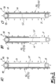
- a flexible drag link 14 is provided which can be moved together with the parking gondolas 5, which according to the exemplary embodiment is a drag chain 14, as can best be seen using the individual functional positions in the Figures 2A to 2C can understand.
- the drag link or drag chain 14 serves to guide a data line 15. The drive chain 7 and the drag chain 14 are moved synchronously.
- a guide device 16 is provided for the individual parking gondolas 5 or the relevant connection plates 6 connected to the drive chain 7.
- the drag chain 14 is shown in the illustration Figures 2A to 2C connected to two fixed points 18 on the head side of the base frame 3. It can be seen that the drag link or the drag chain 14 is guided from one fixed point 18 only via the deflection element 8, which is rotatably mounted on the head side of the basic structure 3, to the other fixed point 18. In contrast, the drive chain 7 is guided circumferentially over both deflection elements 8, which are rotatably connected to the base frame 3 on the head and foot sides. This allows the drag chain 14 to be viewed in the front view Fig. 2A to 2C on the deflection elements 8 between one in the Fig. 2C shown right full sling position, one in the Fig. 2A reproduced left full sling position and one in the Fig. 2B Move to the middle half loop position shown.
- the U-shaped chain links 19a, 19b are equipped with separating webs 20, which ensure that the individual electrical connection lines 13 and also the data line 15 can be separated from one another. In this way it is ensured that the individual lines 13, 15 are usually guided separately next to one another and in two (or more) layers one above the other in the chambers of the drag chain 14 formed in this way.
- the individual lines 13, 15 are connected to the drag link or drag chain 14 at regular intervals with the aid of strain relief in order to avoid any friction or mechanical stress on the lines 13, 15.
- an electrical connection line 13 leads to each electrical supply unit or electrical connection unit 12.
- the electrical supply unit 12 is connected to the at least one data line 15. This can best be seen from the illustration in the Figures 2A to 2C comprehend.
- the relevant electrical connection line 13 is then guided, starting from, for example, the left fixed point 18, in a loop over the head-side deflection element 18 to the other fixed point 18.
- the electrical connection line 13 is guided in a loop perpendicular to the plane of the drawing and therefore not visible, for example along the base area 5a of the parking gondola 5 to the electrical connection unit 12 and back again.
- the individual chain links 19a, 19b are equipped with lateral guide pins 21.
- the guide pins 21 ensure engagement with the deflection element 8, which is designed as a double pinion and is rotatably mounted on the head side of the base frame 3.
- the data line 15 is finally connected to one in the Fig. 1 only indicated control unit 22 is connected, which may be provided on the foot side of the basic structure 3.
- the control unit 22 not only is the access control described carried out, but the amount of electrical energy withdrawn is also billed to the associated electrical supply unit 12.
- the control unit 22 can be used, if necessary, in conjunction with a supply company for the electrical energy supply to the individual electrical supply units 12
- the load management already described in the introduction is possible and can be implemented.
- the individual U-shaped chain links 19a, 19b of the drag link or the drag chain 14 are made of plastic according to the exemplary embodiment.
- the individual chain links 19a, 19b are each designed as plastic injection-molded parts.
- the drive chain or the drive link 7 is usually made of steel. The also applies to the basic structure 3 and generally also to the guides or guide devices 16, 17 as well as to the parking gondolas 5.
Landscapes
- Engineering & Computer Science (AREA)
- Mechanical Engineering (AREA)
- Architecture (AREA)
- Power Engineering (AREA)
- Transportation (AREA)
- Civil Engineering (AREA)
- Structural Engineering (AREA)
- Warehouses Or Storage Devices (AREA)
- Charge And Discharge Circuits For Batteries Or The Like (AREA)
Priority Applications (5)
| Application Number | Priority Date | Filing Date | Title |
|---|---|---|---|
| PL21208309.1T PL4006269T3 (pl) | 2021-11-15 | 2021-11-15 | Urządzenie do przechowywania /parkowania pojazdów |
| ES21208309T ES2976158T3 (es) | 2021-11-15 | 2021-11-15 | Dispositivo de almacenamiento/estacionamiento para vehículos |
| EP21208309.1A EP4006269B1 (de) | 2021-11-15 | 2021-11-15 | Lager-/parkvorrichtung für fahrzeuge |
| US17/985,213 US20230151628A1 (en) | 2021-11-15 | 2022-11-11 | Vehicle parking/storage system with charger |
| CY20241100133T CY1126723T1 (el) | 2021-11-15 | 2024-02-15 | Κατασκευη αποθηκης / παρκινγκ για οχηματα |
Applications Claiming Priority (1)
| Application Number | Priority Date | Filing Date | Title |
|---|---|---|---|
| EP21208309.1A EP4006269B1 (de) | 2021-11-15 | 2021-11-15 | Lager-/parkvorrichtung für fahrzeuge |
Publications (3)
| Publication Number | Publication Date |
|---|---|
| EP4006269A1 EP4006269A1 (de) | 2022-06-01 |
| EP4006269C0 EP4006269C0 (de) | 2023-12-27 |
| EP4006269B1 true EP4006269B1 (de) | 2023-12-27 |
Family
ID=78649176
Family Applications (1)
| Application Number | Title | Priority Date | Filing Date |
|---|---|---|---|
| EP21208309.1A Active EP4006269B1 (de) | 2021-11-15 | 2021-11-15 | Lager-/parkvorrichtung für fahrzeuge |
Country Status (5)
| Country | Link |
|---|---|
| US (1) | US20230151628A1 (pl) |
| EP (1) | EP4006269B1 (pl) |
| CY (1) | CY1126723T1 (pl) |
| ES (1) | ES2976158T3 (pl) |
| PL (1) | PL4006269T3 (pl) |
Families Citing this family (3)
| Publication number | Priority date | Publication date | Assignee | Title |
|---|---|---|---|---|
| US6270766B1 (en) | 1992-10-08 | 2001-08-07 | The Kennedy Institute Of Rheumatology | Anti-TNF antibodies and methotrexate in the treatment of arthritis and crohn's disease |
| US11897353B2 (en) * | 2021-04-22 | 2024-02-13 | Dasher Lawless Technologies, LLC | Systems and methods for charging parked vehicles |
| DE102023136462A1 (de) * | 2023-12-22 | 2025-06-26 | VePa Vertical Parking GmbH | Parkvorrichtung zur Bereitstellung von Parkflächen |
Family Cites Families (5)
| Publication number | Priority date | Publication date | Assignee | Title |
|---|---|---|---|---|
| KR100485605B1 (ko) | 2002-12-12 | 2005-04-28 | 동양피씨(주) | 수직순환식 주차장치 |
| DE202017100651U1 (de) | 2017-02-08 | 2017-03-14 | Parkey UG (haftungsbeschränkt) | Vorrichtung zur Aufnahme von Gegenständen |
| IL251245B (en) | 2017-03-16 | 2018-03-29 | Graner Peter | Local electric power station |
| CN110040013B (zh) * | 2019-05-13 | 2024-06-25 | 张家港友诚新能源科技股份有限公司 | 具有电动汽车充电的垂直循环式立体车库无线供电系统 |
| CN112942930A (zh) * | 2021-03-23 | 2021-06-11 | 四川金石东方新材料科技有限公司 | 垂直循环立体车库及具有其的充电中心 |
-
2021
- 2021-11-15 EP EP21208309.1A patent/EP4006269B1/de active Active
- 2021-11-15 ES ES21208309T patent/ES2976158T3/es active Active
- 2021-11-15 PL PL21208309.1T patent/PL4006269T3/pl unknown
-
2022
- 2022-11-11 US US17/985,213 patent/US20230151628A1/en active Pending
-
2024
- 2024-02-15 CY CY20241100133T patent/CY1126723T1/el unknown
Also Published As
| Publication number | Publication date |
|---|---|
| EP4006269A1 (de) | 2022-06-01 |
| EP4006269C0 (de) | 2023-12-27 |
| US20230151628A1 (en) | 2023-05-18 |
| CY1126723T1 (el) | 2026-02-25 |
| ES2976158T3 (es) | 2024-07-24 |
| PL4006269T3 (pl) | 2024-06-17 |
Similar Documents
| Publication | Publication Date | Title |
|---|---|---|
| EP3131781B1 (de) | Ladevorrichtung für ein elektrisch aufladbares fahrzeug | |
| DE102011001712B4 (de) | Stromabnehmersystem und Anlage | |
| EP4006269A1 (de) | Lager-/parkvorrichtung für fahrzeuge | |
| DE202014100481U1 (de) | System und Koppelvorrichtung zum automatischen Ankoppeln einer fahrbaren Maschine, insbesondere eines Container-Stapelkrans, an eine Fahrversorgung, sowie Kupplung hierfür | |
| DE102013113809A1 (de) | Flurförderzeug mit batterie-elektrischem Antrieb | |
| EP3085856A1 (de) | Aufbewahrungssystem für fahrzeuge | |
| EP2455268A1 (de) | Anlage zur Beförderung von Personen | |
| EP4097821A1 (de) | Laderoboter zur induktiven aufladung von fahrzeugen | |
| WO2020144082A1 (de) | Transportable ladestation | |
| EP0157192A2 (de) | Verfahren und Vorrichtung zum Anschliessen des Stromabnehmers eines Trolleyfahrzeugs an ein Stromschienensystem | |
| DE102019214662A1 (de) | Ladestation für einen fahrzeugseitigen Energiespeicher | |
| WO2005115906A2 (en) | Individually-driven lift | |
| DE102020101097A1 (de) | Ladekoppler, Kraftfahrzeug und Ladesystem | |
| DE102019126372A1 (de) | Anordnung zur Kopplung und Energieversorgung eines Lastmoduls mit einem Transportmodul eines modular aufgebauten Transportsystems | |
| DE202011103341U1 (de) | Energiespeichereinheit, Energiespeichereinheitengehäuse und Wechselstation für Energiespeichereinheiten | |
| EP4607749A1 (de) | Mobile energieversorgungseinheit für eine mobile arbeitsmaschine | |
| EP3228492A1 (de) | Energiezuführung für eine umschlagmaschine | |
| DE7629955U1 (de) | Auf- und Abwickelvorrichtung für ein elektrisches Kabel | |
| DE2236215C2 (de) | Battenewechselstation fur von battenegetriebenen Fahrzeugen mitgefuhrte Großbatterien | |
| WO2013075917A1 (de) | Multikupplungssystem zum verbinden von mehreren werkzeugen mit mindestens einer versorgungseinheit | |
| CH703049A2 (de) | Vorrichtung zum Anheben und Absenken von Lasten. | |
| DE202017006527U1 (de) | Regal und System mit Regal und einem fahrerlosen Transportfahrzeug | |
| DE4008370A1 (de) | Energieversorgung bei krananlagen, insbesondere bei kabelkranen | |
| DE3007515A1 (de) | Antriebsvorrichtung, insbesondere fuer parkplatten | |
| DE2118847A1 (de) | Lade- und Wechselstation für die Batterien von Elektrospeicherfahrzeugen |
Legal Events
| Date | Code | Title | Description |
|---|---|---|---|
| PUAI | Public reference made under article 153(3) epc to a published international application that has entered the european phase |
Free format text: ORIGINAL CODE: 0009012 |
|
| STAA | Information on the status of an ep patent application or granted ep patent |
Free format text: STATUS: THE APPLICATION HAS BEEN PUBLISHED |
|
| AK | Designated contracting states |
Kind code of ref document: A1 Designated state(s): AL AT BE BG CH CY CZ DE DK EE ES FI FR GB GR HR HU IE IS IT LI LT LU LV MC MK MT NL NO PL PT RO RS SE SI SK SM TR |
|
| STAA | Information on the status of an ep patent application or granted ep patent |
Free format text: STATUS: REQUEST FOR EXAMINATION WAS MADE |
|
| 17P | Request for examination filed |
Effective date: 20220614 |
|
| RBV | Designated contracting states (corrected) |
Designated state(s): AL AT BE BG CH CY CZ DE DK EE ES FI FR GB GR HR HU IE IS IT LI LT LU LV MC MK MT NL NO PL PT RO RS SE SI SK SM TR |
|
| GRAP | Despatch of communication of intention to grant a patent |
Free format text: ORIGINAL CODE: EPIDOSNIGR1 |
|
| STAA | Information on the status of an ep patent application or granted ep patent |
Free format text: STATUS: GRANT OF PATENT IS INTENDED |
|
| INTG | Intention to grant announced |
Effective date: 20230803 |
|
| GRAS | Grant fee paid |
Free format text: ORIGINAL CODE: EPIDOSNIGR3 |
|
| GRAA | (expected) grant |
Free format text: ORIGINAL CODE: 0009210 |
|
| STAA | Information on the status of an ep patent application or granted ep patent |
Free format text: STATUS: THE PATENT HAS BEEN GRANTED |
|
| AK | Designated contracting states |
Kind code of ref document: B1 Designated state(s): AL AT BE BG CH CY CZ DE DK EE ES FI FR GB GR HR HU IE IS IT LI LT LU LV MC MK MT NL NO PL PT RO RS SE SI SK SM TR |
|
| REG | Reference to a national code |
Ref country code: GB Ref legal event code: FG4D Free format text: NOT ENGLISH |
|
| REG | Reference to a national code |
Ref country code: CH Ref legal event code: EP |
|
| REG | Reference to a national code |
Ref country code: DE Ref legal event code: R096 Ref document number: 502021002279 Country of ref document: DE |
|
| REG | Reference to a national code |
Ref country code: IE Ref legal event code: FG4D Free format text: LANGUAGE OF EP DOCUMENT: GERMAN |
|
| U01 | Request for unitary effect filed |
Effective date: 20240124 |
|
| U07 | Unitary effect registered |
Designated state(s): AT BE BG DE DK EE FI FR IT LT LU LV MT NL PT SE SI Effective date: 20240131 |
|
| PG25 | Lapsed in a contracting state [announced via postgrant information from national office to epo] |
Ref country code: GR Free format text: LAPSE BECAUSE OF FAILURE TO SUBMIT A TRANSLATION OF THE DESCRIPTION OR TO PAY THE FEE WITHIN THE PRESCRIBED TIME-LIMIT Effective date: 20240328 |
|
| PG25 | Lapsed in a contracting state [announced via postgrant information from national office to epo] |
Ref country code: GR Free format text: LAPSE BECAUSE OF FAILURE TO SUBMIT A TRANSLATION OF THE DESCRIPTION OR TO PAY THE FEE WITHIN THE PRESCRIBED TIME-LIMIT Effective date: 20240328 |
|
| PG25 | Lapsed in a contracting state [announced via postgrant information from national office to epo] |
Ref country code: RS Free format text: LAPSE BECAUSE OF FAILURE TO SUBMIT A TRANSLATION OF THE DESCRIPTION OR TO PAY THE FEE WITHIN THE PRESCRIBED TIME-LIMIT Effective date: 20231227 Ref country code: HR Free format text: LAPSE BECAUSE OF FAILURE TO SUBMIT A TRANSLATION OF THE DESCRIPTION OR TO PAY THE FEE WITHIN THE PRESCRIBED TIME-LIMIT Effective date: 20231227 |
|
| PG25 | Lapsed in a contracting state [announced via postgrant information from national office to epo] |
Ref country code: CZ Free format text: LAPSE BECAUSE OF FAILURE TO SUBMIT A TRANSLATION OF THE DESCRIPTION OR TO PAY THE FEE WITHIN THE PRESCRIBED TIME-LIMIT Effective date: 20231227 |
|
| REG | Reference to a national code |
Ref country code: ES Ref legal event code: FG2A Ref document number: 2976158 Country of ref document: ES Kind code of ref document: T3 Effective date: 20240724 |
|
| PG25 | Lapsed in a contracting state [announced via postgrant information from national office to epo] |
Ref country code: SK Free format text: LAPSE BECAUSE OF FAILURE TO SUBMIT A TRANSLATION OF THE DESCRIPTION OR TO PAY THE FEE WITHIN THE PRESCRIBED TIME-LIMIT Effective date: 20231227 |
|
| PG25 | Lapsed in a contracting state [announced via postgrant information from national office to epo] |
Ref country code: SM Free format text: LAPSE BECAUSE OF FAILURE TO SUBMIT A TRANSLATION OF THE DESCRIPTION OR TO PAY THE FEE WITHIN THE PRESCRIBED TIME-LIMIT Effective date: 20231227 Ref country code: SK Free format text: LAPSE BECAUSE OF FAILURE TO SUBMIT A TRANSLATION OF THE DESCRIPTION OR TO PAY THE FEE WITHIN THE PRESCRIBED TIME-LIMIT Effective date: 20231227 Ref country code: RO Free format text: LAPSE BECAUSE OF FAILURE TO SUBMIT A TRANSLATION OF THE DESCRIPTION OR TO PAY THE FEE WITHIN THE PRESCRIBED TIME-LIMIT Effective date: 20231227 Ref country code: CZ Free format text: LAPSE BECAUSE OF FAILURE TO SUBMIT A TRANSLATION OF THE DESCRIPTION OR TO PAY THE FEE WITHIN THE PRESCRIBED TIME-LIMIT Effective date: 20231227 |
|
| REG | Reference to a national code |
Ref country code: DE Ref legal event code: R097 Ref document number: 502021002279 Country of ref document: DE |
|
| PLBE | No opposition filed within time limit |
Free format text: ORIGINAL CODE: 0009261 |
|
| STAA | Information on the status of an ep patent application or granted ep patent |
Free format text: STATUS: NO OPPOSITION FILED WITHIN TIME LIMIT |
|
| 26N | No opposition filed |
Effective date: 20240930 |
|
| U21 | Renewal fee for the european patent with unitary effect paid with additional fee |
Year of fee payment: 4 Effective date: 20250509 |
|
| PG25 | Lapsed in a contracting state [announced via postgrant information from national office to epo] |
Ref country code: MC Free format text: LAPSE BECAUSE OF FAILURE TO SUBMIT A TRANSLATION OF THE DESCRIPTION OR TO PAY THE FEE WITHIN THE PRESCRIBED TIME-LIMIT Effective date: 20231227 |
|
| PGFP | Annual fee paid to national office [announced via postgrant information from national office to epo] |
Ref country code: ES Payment date: 20250530 Year of fee payment: 4 |
|
| PGFP | Annual fee paid to national office [announced via postgrant information from national office to epo] |
Ref country code: NO Payment date: 20250513 Year of fee payment: 4 |
|
| PGFP | Annual fee paid to national office [announced via postgrant information from national office to epo] |
Ref country code: CH Payment date: 20250522 Year of fee payment: 4 |
|
| PG25 | Lapsed in a contracting state [announced via postgrant information from national office to epo] |
Ref country code: CY Free format text: LAPSE BECAUSE OF NON-PAYMENT OF DUE FEES Effective date: 20241115 |
|
| PGFP | Annual fee paid to national office [announced via postgrant information from national office to epo] |
Ref country code: TR Payment date: 20250509 Year of fee payment: 4 |
|
| PG25 | Lapsed in a contracting state [announced via postgrant information from national office to epo] |
Ref country code: IE Free format text: LAPSE BECAUSE OF NON-PAYMENT OF DUE FEES Effective date: 20241115 |
|
| PG25 | Lapsed in a contracting state [announced via postgrant information from national office to epo] |
Ref country code: HU Free format text: LAPSE BECAUSE OF FAILURE TO SUBMIT A TRANSLATION OF THE DESCRIPTION OR TO PAY THE FEE WITHIN THE PRESCRIBED TIME-LIMIT; INVALID AB INITIO Effective date: 20211115 |
|
| PG25 | Lapsed in a contracting state [announced via postgrant information from national office to epo] |
Ref country code: PL Free format text: LAPSE BECAUSE OF NON-PAYMENT OF DUE FEES Effective date: 20241115 |
|
| REG | Reference to a national code |
Ref country code: CH Ref legal event code: U11 Free format text: ST27 STATUS EVENT CODE: U-0-0-U10-U11 (AS PROVIDED BY THE NATIONAL OFFICE) Effective date: 20260505 |