EP4006276A1 - Sliding gate - Google Patents
Sliding gate Download PDFInfo
- Publication number
- EP4006276A1 EP4006276A1 EP21020558.9A EP21020558A EP4006276A1 EP 4006276 A1 EP4006276 A1 EP 4006276A1 EP 21020558 A EP21020558 A EP 21020558A EP 4006276 A1 EP4006276 A1 EP 4006276A1
- Authority
- EP
- European Patent Office
- Prior art keywords
- wing
- gate
- bolt
- door
- housing
- Prior art date
- Legal status (The legal status is an assumption and is not a legal conclusion. Google has not performed a legal analysis and makes no representation as to the accuracy of the status listed.)
- Pending
Links
Images


Classifications
-
- E—FIXED CONSTRUCTIONS
- E06—DOORS, WINDOWS, SHUTTERS, OR ROLLER BLINDS IN GENERAL; LADDERS
- E06B—FIXED OR MOVABLE CLOSURES FOR OPENINGS IN BUILDINGS, VEHICLES, FENCES OR LIKE ENCLOSURES IN GENERAL, e.g. DOORS, WINDOWS, BLINDS, GATES
- E06B5/00—Doors, windows, or like closures for special purposes; Border constructions therefor
- E06B5/10—Doors, windows, or like closures for special purposes; Border constructions therefor for protection against air-raid or other war-like action; for other protective purposes
- E06B5/16—Fireproof doors or similar closures; Adaptations of fixed constructions therefor
- E06B5/162—Fireproof doors having windows or other openings, e.g. for permitting ventilation or escape
-
- A—HUMAN NECESSITIES
- A62—LIFE-SAVING; FIRE-FIGHTING
- A62C—FIRE-FIGHTING
- A62C2/00—Fire prevention or containment
- A62C2/06—Physical fire-barriers
- A62C2/18—Sliding dampers
-
- E—FIXED CONSTRUCTIONS
- E05—LOCKS; KEYS; WINDOW OR DOOR FITTINGS; SAFES
- E05B—LOCKS; ACCESSORIES THEREFOR; HANDCUFFS
- E05B63/00—Locks or fastenings with special structural characteristics
- E05B63/0052—Locks mounted on the "frame" cooperating with means on the "wing"
-
- E—FIXED CONSTRUCTIONS
- E05—LOCKS; KEYS; WINDOW OR DOOR FITTINGS; SAFES
- E05B—LOCKS; ACCESSORIES THEREFOR; HANDCUFFS
- E05B65/00—Locks or fastenings for special use
- E05B65/10—Locks or fastenings for special use for panic or emergency doors
- E05B65/1033—Locks or fastenings for special use for panic or emergency doors emergency release of windows, window grills, escape hatches or the like
-
- E—FIXED CONSTRUCTIONS
- E05—LOCKS; KEYS; WINDOW OR DOOR FITTINGS; SAFES
- E05C—BOLTS OR FASTENING DEVICES FOR WINGS, SPECIALLY FOR DOORS OR WINDOWS
- E05C7/00—Fastening devices specially adapted for two wings
- E05C7/04—Fastening devices specially adapted for two wings for wings which abut when closed
- E05C7/06—Fastening devices specially adapted for two wings for wings which abut when closed a fastening device for one wing being actuated or controlled by closing another wing
-
- E—FIXED CONSTRUCTIONS
- E05—LOCKS; KEYS; WINDOW OR DOOR FITTINGS; SAFES
- E05F—DEVICES FOR MOVING WINGS INTO OPEN OR CLOSED POSITION; CHECKS FOR WINGS; WING FITTINGS NOT OTHERWISE PROVIDED FOR, CONCERNED WITH THE FUNCTIONING OF THE WING
- E05F5/00—Braking devices, e.g. checks; Stops; Buffers
- E05F5/12—Braking devices, e.g. checks; Stops; Buffers specially for preventing the closing of a wing before another wing has been closed
-
- E—FIXED CONSTRUCTIONS
- E05—LOCKS; KEYS; WINDOW OR DOOR FITTINGS; SAFES
- E05B—LOCKS; ACCESSORIES THEREFOR; HANDCUFFS
- E05B47/00—Operating or controlling locks or other fastening devices by electric or magnetic means
- E05B2047/0084—Key or electric means; Emergency release
-
- E—FIXED CONSTRUCTIONS
- E05—LOCKS; KEYS; WINDOW OR DOOR FITTINGS; SAFES
- E05B—LOCKS; ACCESSORIES THEREFOR; HANDCUFFS
- E05B65/00—Locks or fastenings for special use
- E05B65/0007—Locks or fastenings for special use for gates
-
- E—FIXED CONSTRUCTIONS
- E05—LOCKS; KEYS; WINDOW OR DOOR FITTINGS; SAFES
- E05Y—INDEXING SCHEME ASSOCIATED WITH SUBCLASSES E05D AND E05F, RELATING TO CONSTRUCTION ELEMENTS, ELECTRIC CONTROL, POWER SUPPLY, POWER SIGNAL OR TRANSMISSION, USER INTERFACES, MOUNTING OR COUPLING, DETAILS, ACCESSORIES, AUXILIARY OPERATIONS NOT OTHERWISE PROVIDED FOR, APPLICATION THEREOF
- E05Y2201/00—Constructional elements; Accessories therefor
- E05Y2201/20—Brakes; Disengaging means; Holders; Stops; Valves; Accessories therefor
- E05Y2201/218—Holders
- E05Y2201/22—Locks
-
- E—FIXED CONSTRUCTIONS
- E05—LOCKS; KEYS; WINDOW OR DOOR FITTINGS; SAFES
- E05Y—INDEXING SCHEME ASSOCIATED WITH SUBCLASSES E05D AND E05F, RELATING TO CONSTRUCTION ELEMENTS, ELECTRIC CONTROL, POWER SUPPLY, POWER SIGNAL OR TRANSMISSION, USER INTERFACES, MOUNTING OR COUPLING, DETAILS, ACCESSORIES, AUXILIARY OPERATIONS NOT OTHERWISE PROVIDED FOR, APPLICATION THEREOF
- E05Y2800/00—Details, accessories and auxiliary operations not otherwise provided for
- E05Y2800/71—Secondary wings, e.g. pass doors
-
- E—FIXED CONSTRUCTIONS
- E05—LOCKS; KEYS; WINDOW OR DOOR FITTINGS; SAFES
- E05Y—INDEXING SCHEME ASSOCIATED WITH SUBCLASSES E05D AND E05F, RELATING TO CONSTRUCTION ELEMENTS, ELECTRIC CONTROL, POWER SUPPLY, POWER SIGNAL OR TRANSMISSION, USER INTERFACES, MOUNTING OR COUPLING, DETAILS, ACCESSORIES, AUXILIARY OPERATIONS NOT OTHERWISE PROVIDED FOR, APPLICATION THEREOF
- E05Y2900/00—Application of doors, windows, wings or fittings thereof
- E05Y2900/10—Application of doors, windows, wings or fittings thereof for buildings or parts thereof
- E05Y2900/13—Type of wing
- E05Y2900/132—Doors
- E05Y2900/134—Fire doors
Definitions
- the subject of the invention is a sliding gate, particularly a fire gate.
- Such gates are intended mainly for enclosing space and preventing fire from spreading.
- the gate wing is provided with at least one passage door.
- the passage door installed in the gate should be provided with a safety measure preventing door opening during motion - opening/closing the gate wing, as well as when the gate wing remains open.
- the passage door may be opened only when the door is closed.
- a sliding gate including a housing with an entry pocket, placed within the housing of the moving rail and a gate wing with the passage door and a drive system, characterised in that it is equipped with a mechanical locking system located in the top part of the gate, above the passage door, formed by a body made of an closed profile, a tensioning spring attached to the housing at one end and connected to the bolt at the other end, a linkage provided as a steel bar, in the closed position of the gate resting on the housing at one end and holding the bolt in the unlocked position at the other end, a linkage guide made of a closed profile, fixed within the body, a connection socket with a width corresponding to the bolt thickness, located in the top part of the passage door wing, or with an electric locking system located on the gate wing, including an electric bolt with a latch located within the passage door, a battery providing power supply through the electric bolt wires and a latching socket provided at the edges of the door wing.
- the locking system is preferably located within the gate wing, in the area of the door wing, on the side of the door lock.
- the body preferably has a rectangular or a circular cross-section.
- the bolt preferably has the shape of a rectangular plate with one tapered edge.
- the linkage preferably has the shape of a circular or a rectangular cross-section steel bar.
- the guide preferably has the shape of a closed profile with a circular or a rectangular outline.
- the cross-sectional dimensions of the linkage are preferably adapted to the internal dimensions of the guide.
- the electrical locking system couples the electric bolt with the door wing. Locking is the condition prevalent when the electric bolt is not supplied, which is usually the case during a fire. The electric bolt then holds the latch inside the latching socket. The passage door is locked when the gate wing is moving. Unlocking takes place when the gate wing is closed, by switching the power supply on. The electric bolt unlocks the latch from the latching socket and the door wing may be operated. Locking using the electrical bolt is used usually when the gate is provided with a power supply system.
- the design of the locking system is simple to make and operate.
- the locking system enables simple coupling between the passage door and the gate wing when the gate is moving and holding the bolt in the unlocking position when the gate is closed.
- the intermediate door secured against opening during gate motion significantly increases operational safety of the sliding gate.
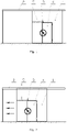
- Fig. 1 - presents the gate in its open position
- Fig. 2 - presents the moving gate
- Fig. 3 - presents the gate in its closed position
- Fig. 4 - presents a front view of the mechanical locking system, partially in a cross-section
- Fig. 5 - presents a side view of the mechanical locking system
- Fig. 6 - presents the gate wing with the door wing locking
- Fig. 7 - presents the gate wing with the door wing unlocking in the closed position
- Fig. 8 - presents the gate with the electrical locking system
- Fig. 9 - presents the door wing locked with the gate wing using an electrical locking system
- Fig. 10 - presents the door wing and the gate wing in the unlocked position.
- the sliding gate is fixed inside a housing. It is built out of a gate wing 1 suspended on a moving rail 2 and intermediate door 3 placed in it, with a door wing 4, a drive system and a locking system.
- the mechanical locking system 5 is located in the top part of the gate, above the passage door 3, in the corner area of the door wing 4, on the side of the door lock.
- the locking system 5 comprises of a body 6 in the shape of a closed profile, fixed to the gate wing 1, a bolt 7 in the shape of a rectangular plate with one tapered corner, installed and rotating on a pin 8 fixed in the body 6, a tensioning spring 9 fixed to the body 6 at one end, and on the other end - connected with the bolt 7, a linkage 10 in the form of a steel bar, sliding inside a guide 11 in the shape of a closed profile, fixed to the interior of the body 6 and a latching socket 12 placed in the top part of the door wing 4.
- the latching socket 12 cooperates with the bolt 7.
- the bolt 7 passes through the latching socket 12 and blocks the opening of the passage door 3 during gate motion.
- the linkage 10 In the closed position of the sliding gate, the linkage 10 rests at one end against the housing and the other end holds the bolt 7 in a position moved away from the latching socket 12, such that the door wing 4 is released and may open.
- the end of the linkage 10 moves away from the housing and the linkage 10 will move due to the pressure of the bolt 7 caused by the tensioning spring 9, causing the bolt 10 to move onto the latching socket 12 and locking the door wing 4.
- the length of the linkage 10 and of the body 7 depends on the dimensions of the wing gate 1 and of the passage door 3 placed in it.
- the electrical locking system 13 is placed on the gate wing 1. It includes and electric lock 14 with a latch 15, a battery 16 powering the electric lock 14 and a latching socket 16 installed on the edges of the door wing 4.
- the door wing 4 becomes locked with the gate wing 1 when the electric lock 14 is not energised. This is significant during a fire, when the power supply system is inoperational. Unlocking takes place when the power supply is switched on. This improves safety during the use of sliding gates.
- the locking system 5 may be placed vertically.
- This solution may also be used with gates with low gates, by placing the locking systems in a horizontal position.
Landscapes
- Engineering & Computer Science (AREA)
- Structural Engineering (AREA)
- Business, Economics & Management (AREA)
- Emergency Management (AREA)
- Civil Engineering (AREA)
- Mechanical Engineering (AREA)
- Health & Medical Sciences (AREA)
- Public Health (AREA)
- Gates (AREA)
- Special Wing (AREA)
Applications Claiming Priority (1)
| Application Number | Priority Date | Filing Date | Title |
|---|---|---|---|
| PL436006A PL436006A1 (pl) | 2020-11-18 | 2020-11-18 | Brama przesuwna |
Publications (1)
| Publication Number | Publication Date |
|---|---|
| EP4006276A1 true EP4006276A1 (en) | 2022-06-01 |
Family
ID=78676256
Family Applications (1)
| Application Number | Title | Priority Date | Filing Date |
|---|---|---|---|
| EP21020558.9A Pending EP4006276A1 (en) | 2020-11-18 | 2021-11-09 | Sliding gate |
Country Status (2)
| Country | Link |
|---|---|
| EP (1) | EP4006276A1 (pl) |
| PL (1) | PL436006A1 (pl) |
Citations (3)
| Publication number | Priority date | Publication date | Assignee | Title |
|---|---|---|---|---|
| DE7003508U (de) * | 1970-02-03 | 1970-05-06 | Schwarze Ag Metalltueren | Geteilter torfluegel. |
| EP0505350A1 (de) * | 1991-03-19 | 1992-09-23 | Manfred Sterrer | Drehscheiben-Schliessfolge- und Verriegelungseinrichtung |
| DE102014105655A1 (de) * | 2014-04-22 | 2015-10-22 | Novoferm Riexinger Türenwerke GmbH | Schiebetor, insbesondere Brandschutzschiebetor |
-
2020
- 2020-11-18 PL PL436006A patent/PL436006A1/pl unknown
-
2021
- 2021-11-09 EP EP21020558.9A patent/EP4006276A1/en active Pending
Patent Citations (3)
| Publication number | Priority date | Publication date | Assignee | Title |
|---|---|---|---|---|
| DE7003508U (de) * | 1970-02-03 | 1970-05-06 | Schwarze Ag Metalltueren | Geteilter torfluegel. |
| EP0505350A1 (de) * | 1991-03-19 | 1992-09-23 | Manfred Sterrer | Drehscheiben-Schliessfolge- und Verriegelungseinrichtung |
| DE102014105655A1 (de) * | 2014-04-22 | 2015-10-22 | Novoferm Riexinger Türenwerke GmbH | Schiebetor, insbesondere Brandschutzschiebetor |
Also Published As
| Publication number | Publication date |
|---|---|
| PL436006A1 (pl) | 2022-05-23 |
Similar Documents
| Publication | Publication Date | Title |
|---|---|---|
| US3325203A (en) | Sliding door lock | |
| US8146966B1 (en) | Integration of vertical adjustability in an electric strike | |
| CA3002386C (en) | Electric door strike having a dead latch release platform actuated by a spring latch keeper and a spring latch lifter feature | |
| US8157302B1 (en) | Integration of vertical adjustability in an electric strike | |
| MXPA05012240A (es) | Disposicion para guiar el cerrojo dormido de un pestillo de resorte en un cerrojo de puerta. | |
| US20130009409A1 (en) | Electric lock device | |
| CN105133952B (zh) | 具有螺线管释放门闩锁的竖直门锁定系统 | |
| CN204627190U (zh) | 一种防盗门锁的锁舌结构 | |
| US20190031468A1 (en) | Mechanical hoistway access control device | |
| CA2265402A1 (en) | Door system for a mine stopping | |
| CN213742795U (zh) | 地铁安全门锁机构 | |
| EP3190247A1 (en) | Closing device for security locks | |
| EP2171187B1 (en) | Lock for reinforced doors and the like comprising a selector | |
| SE0300750D0 (sv) | Säkerhetslås | |
| EP3250767B1 (en) | A lock | |
| US918316A (en) | Safety locking-bolt. | |
| KR100900888B1 (ko) | 하이브리드형 잠금장치 | |
| KR102955875B1 (ko) | 도어구조 | |
| JPH0610545A (ja) | 扉用電気錠装置 | |
| ES2133031A1 (es) | Grupo de cierre. | |
| CN201092761Y (zh) | 具有安全锁体结构的锁具 | |
| CN110952841B (zh) | 一种机柜用锁具 | |
| US20050262770A1 (en) | Security door | |
| JP2004245041A (ja) | 電磁石錠装置 | |
| PL436006A1 (pl) | Brama przesuwna |
Legal Events
| Date | Code | Title | Description |
|---|---|---|---|
| PUAI | Public reference made under article 153(3) epc to a published international application that has entered the european phase |
Free format text: ORIGINAL CODE: 0009012 |
|
| STAA | Information on the status of an ep patent application or granted ep patent |
Free format text: STATUS: REQUEST FOR EXAMINATION WAS MADE |
|
| 17P | Request for examination filed |
Effective date: 20211118 |
|
| AK | Designated contracting states |
Kind code of ref document: A1 Designated state(s): AL AT BE BG CH CY CZ DE DK EE ES FI FR GB GR HR HU IE IS IT LI LT LU LV MC MK MT NL NO PL PT RO RS SE SI SK SM TR |
|
| P01 | Opt-out of the competence of the unified patent court (upc) registered |
Effective date: 20230531 |
|
| RAP3 | Party data changed (applicant data changed or rights of an application transferred) |
Owner name: ZENON MALKOWSKI |
|
| RAP1 | Party data changed (applicant data changed or rights of an application transferred) |
Owner name: ASSA ABLOY MERCOR DOORS SPOLKA ZOGRANICZONA ODPOWIEDZIALNOSCIA |