EP4006279A1 - Mécanisme de charnière pour porte basculante - Google Patents
Mécanisme de charnière pour porte basculante Download PDFInfo
- Publication number
- EP4006279A1 EP4006279A1 EP19938782.0A EP19938782A EP4006279A1 EP 4006279 A1 EP4006279 A1 EP 4006279A1 EP 19938782 A EP19938782 A EP 19938782A EP 4006279 A1 EP4006279 A1 EP 4006279A1
- Authority
- EP
- European Patent Office
- Prior art keywords
- rotating
- door
- rotating block
- block
- hinge
- Prior art date
- Legal status (The legal status is an assumption and is not a legal conclusion. Google has not performed a legal analysis and makes no representation as to the accuracy of the status listed.)
- Withdrawn
Links
- 230000003139 buffering effect Effects 0.000 claims description 3
- 238000003825 pressing Methods 0.000 claims description 3
- 238000010586 diagram Methods 0.000 description 5
- 238000005452 bending Methods 0.000 description 2
- 238000013016 damping Methods 0.000 description 2
- 230000009286 beneficial effect Effects 0.000 description 1
- 238000000034 method Methods 0.000 description 1
- 239000007787 solid Substances 0.000 description 1
Images


Classifications
-
- E—FIXED CONSTRUCTIONS
- E05—LOCKS; KEYS; WINDOW OR DOOR FITTINGS; SAFES
- E05F—DEVICES FOR MOVING WINGS INTO OPEN OR CLOSED POSITION; CHECKS FOR WINGS; WING FITTINGS NOT OTHERWISE PROVIDED FOR, CONCERNED WITH THE FUNCTIONING OF THE WING
- E05F3/00—Closers or openers with braking devices, e.g. checks; Construction of pneumatic or liquid braking devices
- E05F3/20—Closers or openers with braking devices, e.g. checks; Construction of pneumatic or liquid braking devices in hinges
-
- E—FIXED CONSTRUCTIONS
- E05—LOCKS; KEYS; WINDOW OR DOOR FITTINGS; SAFES
- E05F—DEVICES FOR MOVING WINGS INTO OPEN OR CLOSED POSITION; CHECKS FOR WINGS; WING FITTINGS NOT OTHERWISE PROVIDED FOR, CONCERNED WITH THE FUNCTIONING OF THE WING
- E05F1/00—Closers or openers for wings, not otherwise provided for in this subclass
- E05F1/08—Closers or openers for wings, not otherwise provided for in this subclass spring-actuated, e.g. for horizontally sliding wings
- E05F1/10—Closers or openers for wings, not otherwise provided for in this subclass spring-actuated, e.g. for horizontally sliding wings for swinging wings, e.g. counterbalance
- E05F1/12—Mechanisms in the shape of hinges or pivots, operated by springs
- E05F1/1246—Mechanisms in the shape of hinges or pivots, operated by springs with a coil spring perpendicular to the pivot axis
- E05F1/1253—Mechanisms in the shape of hinges or pivots, operated by springs with a coil spring perpendicular to the pivot axis with a compression spring
- E05F1/1261—Mechanisms in the shape of hinges or pivots, operated by springs with a coil spring perpendicular to the pivot axis with a compression spring for counterbalancing
-
- E—FIXED CONSTRUCTIONS
- E05—LOCKS; KEYS; WINDOW OR DOOR FITTINGS; SAFES
- E05D—HINGES OR SUSPENSION DEVICES FOR DOORS, WINDOWS OR WINGS
- E05D11/00—Additional features or accessories of hinges
-
- E—FIXED CONSTRUCTIONS
- E05—LOCKS; KEYS; WINDOW OR DOOR FITTINGS; SAFES
- E05D—HINGES OR SUSPENSION DEVICES FOR DOORS, WINDOWS OR WINGS
- E05D11/00—Additional features or accessories of hinges
- E05D11/10—Devices for preventing movement between relatively-movable hinge parts
-
- E—FIXED CONSTRUCTIONS
- E05—LOCKS; KEYS; WINDOW OR DOOR FITTINGS; SAFES
- E05D—HINGES OR SUSPENSION DEVICES FOR DOORS, WINDOWS OR WINGS
- E05D15/00—Suspension arrangements for wings
- E05D15/40—Suspension arrangements for wings supported on arms movable in vertical planes
-
- E—FIXED CONSTRUCTIONS
- E05—LOCKS; KEYS; WINDOW OR DOOR FITTINGS; SAFES
- E05D—HINGES OR SUSPENSION DEVICES FOR DOORS, WINDOWS OR WINGS
- E05D5/00—Construction of single parts, e.g. the parts for attachment
- E05D5/02—Parts for attachment, e.g. flaps
-
- E—FIXED CONSTRUCTIONS
- E05—LOCKS; KEYS; WINDOW OR DOOR FITTINGS; SAFES
- E05F—DEVICES FOR MOVING WINGS INTO OPEN OR CLOSED POSITION; CHECKS FOR WINGS; WING FITTINGS NOT OTHERWISE PROVIDED FOR, CONCERNED WITH THE FUNCTIONING OF THE WING
- E05F5/00—Braking devices, e.g. checks; Stops; Buffers
- E05F5/02—Braking devices, e.g. checks; Stops; Buffers specially for preventing the slamming of swinging wings during final closing movement, e.g. jamb stops
-
- E—FIXED CONSTRUCTIONS
- E05—LOCKS; KEYS; WINDOW OR DOOR FITTINGS; SAFES
- E05Y—INDEXING SCHEME ASSOCIATED WITH SUBCLASSES E05D AND E05F, RELATING TO CONSTRUCTION ELEMENTS, ELECTRIC CONTROL, POWER SUPPLY, POWER SIGNAL OR TRANSMISSION, USER INTERFACES, MOUNTING OR COUPLING, DETAILS, ACCESSORIES, AUXILIARY OPERATIONS NOT OTHERWISE PROVIDED FOR, APPLICATION THEREOF
- E05Y2201/00—Constructional elements; Accessories therefor
- E05Y2201/60—Suspension or transmission members; Accessories therefor
- E05Y2201/622—Suspension or transmission members elements
- E05Y2201/638—Cams; Ramps
-
- E—FIXED CONSTRUCTIONS
- E05—LOCKS; KEYS; WINDOW OR DOOR FITTINGS; SAFES
- E05Y—INDEXING SCHEME ASSOCIATED WITH SUBCLASSES E05D AND E05F, RELATING TO CONSTRUCTION ELEMENTS, ELECTRIC CONTROL, POWER SUPPLY, POWER SIGNAL OR TRANSMISSION, USER INTERFACES, MOUNTING OR COUPLING, DETAILS, ACCESSORIES, AUXILIARY OPERATIONS NOT OTHERWISE PROVIDED FOR, APPLICATION THEREOF
- E05Y2900/00—Application of doors, windows, wings or fittings thereof
- E05Y2900/20—Application of doors, windows, wings or fittings thereof for furniture, e.g. cabinets
Definitions
- the present invention relates to a hinge mechanism and particularly relates to an overhead door hinge mechanism.
- a hinge is a mechanical device used for connecting two solid objects and allowing the relative rotation thereof, and an overhead door hinge is mainly used in a joint of a box body or cabinet body provided with a cover door and can realize closing and opening of the cover door on the box body.
- the purpose of the present invention is to provide an overhead door hinge mechanism to solve problems proposed in the above background art of the invention.
- An overhead door hinge mechanism comprises a hinge box boy, wherein the side wall of the hinge box body is provided with a telescopic arm assembly used for connecting with the door backplane of an overhead door, the telescopic arm assembly is provided with a two-stage rotating arm mechanism used for driving the door backplane to upwards flip over the range of a right angle, a connecting and rotating block and a spring stress block are rotationally fixed in the hinge box body, the telescopic arm assembly is rotationally fixed on the side wall of the hinge box body through the connecting and rotating block, and a clamping mechanism used for limiting the rotation of the connecting and rotating block is arranged between the spring stress block and the connecting and rotating block.
- the spring stress block is provided with a hinge spring used for rotationally applying pressure on the spring stress block on one side away from sliding connection with the connecting and rotating block.
- the two-stage rotating arm mechanism comprises a long arm support, a short arm support and a door panel fixing frame, the long arm support and the short arm support are rotationally fixed on the panel of one side of the connecting and rotating block at an interval, the outside ends of the long arm support and the short arm support are fixed on one end of the door panel fixing frame at an interval, and the panel of the door panel fixing frame relative to the rotating connection of the long arm support and the short arm support is used for fixed connection with the door backplane of the overhead door.
- a damper used for buffering the telescopic arm assembly during retraction and extension is arranged in the hinge box body, and the damper is rotationally connected with the connecting and rotating block.
- the clamping mechanism comprises a sliding groove and a rotating and sliding arc edge
- the rotating and sliding arc edge is arranged in the side wall position connected with the connecting and rotating block and the spring stress block
- the sliding groove is arranged in the side wall connected with the connecting and rotating block
- the sliding groove is an annular opening groove
- the connecting and rotating block is integrally clamped in the sliding groove through the rotating and sliding arc edge
- a bearing ring for facilitating sliding of the connecting and rotating block is sleeved in the sliding groove.
- the present invention has the beneficial effects that: the telescopic arm assembly arranged in the present invention can drive the door panel fixing frame used for fixing the door body to realize the turning from a vertical position to a horizontal position through mutual matching of the long arm support and the short arm support through two-stage rotary bending, the clamping mechanism arranged in the present invention can effectively keep the door panel fixing frame in a vertical or horizontal state to reduce mechanical loss of the hinge spring, the damper arranged in the present invention can slow down application of elastic force of the hinge spring during turning to keep the telescopic arm assembly slowly open or close as a whole, thus greatly improving the overall turning smoothness of the door panel fixing frame, and the present invention has long overall service life and can be effectively used for connection of various cover doors and cabinets needing overhead doors.
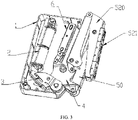
- hinge box body 1 bottom box 10, cover plate 11, accommodating groove 12, hinge spring 2, spring stress block 3, sliding groove 30, connecting and rotating block 4, sliding arc edge 40, telescopic arm assembly 5, long arm support 50, short arm support 51, door panel fixing frame 52, rotary connecting plate 520, fixed trough plate 521 and damper 6.
- an overhead door hinge mechanism comprises a hinge box boy 1, wherein the side wall of the hinge box body 1 is provided with a telescopic arm assembly 5 used for connecting with the door backplane of an overhead door, the telescopic arm assembly 5 is provided with a two-stage rotating arm mechanism used for driving the door backplane to upwards flip over the range of a right angle, a connecting and rotating block 4 and a spring stress block 3 are rotationally fixed in the hinge box body 1, the telescopic arm assembly 5 is rotationally fixed on the side wall of the hinge box body 1 through the connecting and rotating block 4, and a clamping mechanism used for limiting the rotation of the connecting and rotating block 4 is arranged between the spring stress block 3 and the connecting and rotating block 4.
- the spring stress block 3 is provided with a hinge spring 2 used for rotationally applying pressure on the spring stress block 3 on one side away from sliding connection with the connecting and rotating block 4.
- the two-stage rotating arm mechanism comprises a long arm support 50, a short arm support 51 and a door panel fixing frame 52, the long arm support 50 and the short arm support 51 are rotationally fixed on the panel of one side of the connecting and rotating block 4 at an interval, the outside ends of the long arm support 50 and the short arm support 51 are fixed on one end of the door panel fixing frame 52 at an interval, and the panel of the door panel fixing frame 52 relative to the rotating connection of the long arm support 50 and the short arm support 51 is used for fixed connection with the door backplane of the overhead door.
- the door panel fixing frame 52 comprises rotary connecting plates 520 and a fixed trough plate 521, the fixed trough plate 521 is trough section, the trough wall of one end of the fixed trough plate 521 is fixed with two rotary connecting plates 520 opposite to each other in parallel, and the left end and the right end of each rotary connecting plate 520 are respectively in rotary and fixed connection with the outside ends of the short arm support 51 and the long arm support 50.
- the clamping mechanism comprises a sliding groove 30 and a rotating and sliding arc edge 40, the rotating and sliding arc edge 40 is arranged in the side wall position connected with the connecting and rotating block 4 and the spring stress block 3, the sliding groove 30 is arranged in the side wall connected with the connecting and rotating block 4, the sliding groove 30 is an annular opening groove, the connecting and rotating block 4 is integrally clamped in the sliding groove 30 through the rotating and sliding arc edge 40, and a bearing ring for facilitating sliding of the connecting and rotating block 4 is sleeved in the sliding groove 30.
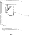
- the hinge box body 1 comprises a bottom box 10 and a cover plate 11, the cover plate 11 is covered on the bottom box 10, the bottom box 10 is provided with a notch for rotary connection of the connecting and rotating block 4 and the telescopic arm assembly 5 on the side wall located on one side of the telescopic arm assembly 5, and an accommodating groove 12 for attaching and accommodating the telescopic arm assembly 5 on the side wall of the bottom box 10 is arranged at the notch.
- the present invention has the working principle that: in use, the bottom surface of the bottom box 10 of the hinge box body 1 is attached to the side wall of the box body in the overhead door body, and the hinge box body 1 is vertically installed, wherein the door panel fixing frame 52 is fixedly connected with the door backplane of the overhead door; when the short arm support 51 of the telescopic arm assembly 5 is accommodated in the accommodating groove 12, the long arm support 50 is rotationally attached to the outer side of the short arm support 51, and the door panel fixing frame 52 is rotationally attached to the outer side wall of the long arm support 50, the door body fixed on the door panel fixing frame 52 is vertically placed, the door body is in a closed state, and the connecting and rotating block 4 is clamped in the sliding groove 30 of the spring stress block 3 through the clamping mechanism; when the door body is pulled by external force, the door panel fixing frame 52 is first flipped upwards, and then the long arm support 50 is expanded outwards and drives the connecting and rotating block 4 to slide in the sliding groove 30 until the long arm support 50 pushe
- the embodiment is different from embodiment 1 in that: A damper 6 used for buffering the telescopic arm assembly 5 during retraction and extension is arranged in the hinge box body 1, and the damper 6 is rotationally connected with the connecting and rotating block 4.
- the rotating point of the connecting and rotating block 4 and the hinge box body 1 is arranged in the center position of the connecting and rotating block 4, an arm shaft hole for rotary fixation of the telescopic arm assembly 5 is reserved in the panel of one side of the connecting and rotating block 4 near the telescopic arm assembly 5, one side of the arm shaft hole opposite to the center position of the connecting and rotating block 4 is provided with a damper shaft hole, the telescopic end of the damper 6 is rotationally connected with the connecting and rotating block 4 through the damper shaft hole, and the damper 6 is installed in the hinge box body 1.
- the present invention has the working principle that: the damper 6 arranged in the present invention can slow down application of elastic force of the hinge spring 2 during turning to keep the telescopic arm assembly 5 slowly open or close as a whole, thus greatly improving the overall turning smoothness of the door panel fixing frame 52.
Landscapes
- Engineering & Computer Science (AREA)
- Mechanical Engineering (AREA)
- Closing And Opening Devices For Wings, And Checks For Wings (AREA)
- Hinges (AREA)
- Pivots And Pivotal Connections (AREA)
Applications Claiming Priority (2)
| Application Number | Priority Date | Filing Date | Title |
|---|---|---|---|
| CN201910667576.6A CN110284790B (zh) | 2019-07-23 | 2019-07-23 | 一种翻门铰链机构 |
| PCT/CN2019/101319 WO2021012335A1 (fr) | 2019-07-23 | 2019-08-19 | Mécanisme de charnière pour porte basculante |
Publications (2)
| Publication Number | Publication Date |
|---|---|
| EP4006279A1 true EP4006279A1 (fr) | 2022-06-01 |
| EP4006279A4 EP4006279A4 (fr) | 2023-08-30 |
Family
ID=68023892
Family Applications (1)
| Application Number | Title | Priority Date | Filing Date |
|---|---|---|---|
| EP19938782.0A Withdrawn EP4006279A4 (fr) | 2019-07-23 | 2019-08-19 | Mécanisme de charnière pour porte basculante |
Country Status (4)
| Country | Link |
|---|---|
| US (1) | US20210372186A1 (fr) |
| EP (1) | EP4006279A4 (fr) |
| CN (1) | CN110284790B (fr) |
| WO (1) | WO2021012335A1 (fr) |
Cited By (1)
| Publication number | Priority date | Publication date | Assignee | Title |
|---|---|---|---|---|
| WO2024231205A1 (fr) * | 2023-05-08 | 2024-11-14 | Hettich-Heinze Gmbh & Co. Kg | Ferrure de porte et meuble |
Families Citing this family (5)
| Publication number | Priority date | Publication date | Assignee | Title |
|---|---|---|---|---|
| US11683866B2 (en) * | 2018-11-06 | 2023-06-20 | Guangdong Midea Kitchen Appliances Manufacturing Co., Ltd. | Microwave oven |
| CN111042684A (zh) * | 2020-01-17 | 2020-04-21 | 广东星徽精密制造股份有限公司 | 一种任意角度悬停的上翻门铰链 |
| USD1056697S1 (en) * | 2022-07-25 | 2025-01-07 | Julius Blum Gmbh | Furniture fitting |
| JP1752599S (ja) | 2022-07-25 | 2023-09-07 | 家具用部品用部材 | |
| CN115874889B (zh) * | 2022-11-30 | 2026-01-23 | 清远市星徽精密制造有限公司 | 一种上翻折叠门用的铰链安全系统 |
Family Cites Families (24)
| Publication number | Priority date | Publication date | Assignee | Title |
|---|---|---|---|---|
| CN2156258Y (zh) * | 1993-05-22 | 1994-02-16 | 毛静庄 | 翻门铰链 |
| JP3339837B2 (ja) * | 1999-05-28 | 2002-10-28 | スガツネ工業株式会社 | 回動扉をもったオーバーヘッドキャビネット |
| DE19945755A1 (de) * | 1999-09-24 | 2001-03-29 | Witte Velbert Gmbh & Co Kg | Klappenscharnieranordnung |
| DE10223026C5 (de) * | 2002-05-22 | 2007-11-08 | Huwil-Werke Gmbh Möbelschloss- Und Beschlagfabriken | Deckelsteller |
| TW589434B (en) * | 2002-11-13 | 2004-06-01 | Salice Arturo Spa | Hinge |
| DE202004020900U1 (de) * | 2004-04-23 | 2006-11-02 | Hetal-Werke Franz Hettich Gmbh & Co. Kg | Klappenbeschlag |
| ITMI20050181A1 (it) * | 2005-02-09 | 2006-08-10 | Effegi Brevetti Srl | Dispositivo di apertura-chiusura di un'anta a ribalta di un mobile |
| DE102006007702B4 (de) * | 2006-02-13 | 2009-04-23 | Hetal-Werke Franz Hettich Gmbh & Co. Kg | Beschlagvorrichtung für eine Möbelklappe |
| DE102008005463A1 (de) * | 2008-01-21 | 2009-07-23 | Huwil-Werke Gmbh Möbelschloss- Und Beschlagfabriken | Halteelement zum Verstellen eines Deckels eines Möbels |
| AT508529A1 (de) * | 2009-07-28 | 2011-02-15 | Blum Gmbh Julius | Stellantrieb für ein bewegbares möbelteil |
| CN202913834U (zh) * | 2012-10-26 | 2013-05-01 | 何厚荣 | 一种嵌入式电冰箱门铰链 |
| AT515492B1 (de) * | 2014-03-14 | 2020-01-15 | Blum Gmbh Julius | Stellantrieb für Möbelklappen |
| CN105332584B (zh) * | 2015-10-27 | 2019-03-01 | 东莞市索迈罗金属科技有限公司 | 一种多功能柜门铰链 |
| AT16381U1 (de) * | 2016-02-26 | 2019-08-15 | Blum Gmbh Julius | Stellarmantrieb |
| CN205617975U (zh) * | 2016-04-26 | 2016-10-05 | 伍志勇 | 一种家具铰链的阻尼器保护装置 |
| DE102017114775A1 (de) * | 2017-07-03 | 2019-01-03 | Hettich-Oni Gmbh & Co. Kg | Klappenbeschlag und Möbel |
| CN207436761U (zh) * | 2017-11-10 | 2018-06-01 | 广东东泰五金精密制造有限公司 | 一种大盖位家具铰链 |
| DE102017126366A1 (de) * | 2017-11-10 | 2019-05-16 | Hettich-Oni Gmbh & Co. Kg | Klappenbeschlag für ein Möbel, Seitenwand eines Möbelkorpus und Möbel mit einer Seitenwand |
| DE102017126367A1 (de) * | 2017-11-10 | 2019-05-16 | Hettich-Oni Gmbh & Co. Kg | Klappenbeschlag für ein Möbel, Seitenwand eines Möbelkorpus und Möbel mit einer Seitenwand |
| CN207794885U (zh) * | 2017-12-29 | 2018-08-31 | 宁波北仑捷腾智能家居有限公司 | 一种三维调节天地铰链 |
| CN108505861B (zh) * | 2018-05-09 | 2023-08-15 | 广东东泰五金精密制造有限公司 | 一种用于家具上翻折叠门的防夹手机构 |
| CN109838165B (zh) * | 2019-03-23 | 2023-11-07 | 广东星徽精密制造股份有限公司 | 一种上翻门铰链用的缓冲装置 |
| CN110284785B (zh) * | 2019-05-30 | 2024-10-11 | 东莞市楷模家居用品制造有限公司 | 一种用于家具上翻支撑的可调节省力机构 |
| CN210460289U (zh) * | 2019-07-23 | 2020-05-05 | 广东星徽精密制造股份有限公司 | 一种翻门铰链机构 |
-
2019
- 2019-07-23 CN CN201910667576.6A patent/CN110284790B/zh active Active
- 2019-08-19 WO PCT/CN2019/101319 patent/WO2021012335A1/fr not_active Ceased
- 2019-08-19 EP EP19938782.0A patent/EP4006279A4/fr not_active Withdrawn
-
2021
- 2021-08-10 US US17/399,044 patent/US20210372186A1/en not_active Abandoned
Cited By (1)
| Publication number | Priority date | Publication date | Assignee | Title |
|---|---|---|---|---|
| WO2024231205A1 (fr) * | 2023-05-08 | 2024-11-14 | Hettich-Heinze Gmbh & Co. Kg | Ferrure de porte et meuble |
Also Published As
| Publication number | Publication date |
|---|---|
| CN110284790A (zh) | 2019-09-27 |
| US20210372186A1 (en) | 2021-12-02 |
| EP4006279A4 (fr) | 2023-08-30 |
| WO2021012335A1 (fr) | 2021-01-28 |
| CN110284790B (zh) | 2024-05-10 |
Similar Documents
| Publication | Publication Date | Title |
|---|---|---|
| EP4006279A1 (fr) | Mécanisme de charnière pour porte basculante | |
| EP2084357B1 (fr) | Charnière pour fenêtre de toit ayant un châssis pivotant | |
| ATE320539T1 (de) | Mehrgelenkscharnier | |
| WO2023284042A1 (fr) | Charnière de fermeture de porte automatique, sûre et tampon | |
| CN215889720U (zh) | 铰链及具有其的制冷设备 | |
| WO2022194234A1 (fr) | Charnière et dispositif de réfrigération pourvue de celle-ci | |
| JP2021526200A (ja) | V字型の軸付きの隠しヒンジ | |
| EP3241967B1 (fr) | Charnière de porte à quatre articulations en mesure de se fermer automatiquement de manière amortie | |
| CN210460289U (zh) | 一种翻门铰链机构 | |
| CN114704171A (zh) | 一种铰链用的摩擦保持机构 | |
| US11149483B2 (en) | Furniture hinge, furniture panel, and furniture body | |
| US2584372A (en) | Hinge | |
| CN210563961U (zh) | 铰链 | |
| CN209637383U (zh) | 一种门拉手组件 | |
| CN210888485U (zh) | 一种卧式助力铰链 | |
| CN213015887U (zh) | 一种便于安装的门铰链 | |
| CN222267648U (zh) | 一种开门机构及点胶设备 | |
| CN211397087U (zh) | 一种缓冲型可调式铰链 | |
| CN210918623U (zh) | 一种上翻门铰链用的伸缩旋转臂架机构 | |
| CN207641733U (zh) | 一种精密气动转台 | |
| CN219365745U (zh) | 一种具有折弯结构的铰链 | |
| CN220539460U (zh) | 一种自定位合页 | |
| CN221997315U (zh) | 一种抽屉及床头柜 | |
| CN210768281U (zh) | 一种冰箱嵌入式铰链弹簧机构 | |
| CN217631908U (zh) | 一种可微调的180°铰链 |
Legal Events
| Date | Code | Title | Description |
|---|---|---|---|
| STAA | Information on the status of an ep patent application or granted ep patent |
Free format text: STATUS: THE INTERNATIONAL PUBLICATION HAS BEEN MADE |
|
| PUAI | Public reference made under article 153(3) epc to a published international application that has entered the european phase |
Free format text: ORIGINAL CODE: 0009012 |
|
| STAA | Information on the status of an ep patent application or granted ep patent |
Free format text: STATUS: REQUEST FOR EXAMINATION WAS MADE |
|
| 17P | Request for examination filed |
Effective date: 20210802 |
|
| AK | Designated contracting states |
Kind code of ref document: A1 Designated state(s): AL AT BE BG CH CY CZ DE DK EE ES FI FR GB GR HR HU IE IS IT LI LT LU LV MC MK MT NL NO PL PT RO RS SE SI SK SM TR |
|
| DAV | Request for validation of the european patent (deleted) | ||
| DAX | Request for extension of the european patent (deleted) | ||
| A4 | Supplementary search report drawn up and despatched |
Effective date: 20230727 |
|
| RIC1 | Information provided on ipc code assigned before grant |
Ipc: E05F 5/02 20060101ALI20230721BHEP Ipc: E05D 15/40 20060101ALI20230721BHEP Ipc: E05F 1/12 20060101ALI20230721BHEP Ipc: E05D 11/00 20060101ALI20230721BHEP Ipc: E05D 11/10 20060101ALI20230721BHEP Ipc: E05D 5/02 20060101AFI20230721BHEP |
|
| STAA | Information on the status of an ep patent application or granted ep patent |
Free format text: STATUS: THE APPLICATION IS DEEMED TO BE WITHDRAWN |
|
| 18D | Application deemed to be withdrawn |
Effective date: 20240227 |