EP4006312A1 - Joint d'étanchéité à l'air extérieur de lame composite à matrice céramique - Google Patents
Joint d'étanchéité à l'air extérieur de lame composite à matrice céramique Download PDFInfo
- Publication number
- EP4006312A1 EP4006312A1 EP21215902.4A EP21215902A EP4006312A1 EP 4006312 A1 EP4006312 A1 EP 4006312A1 EP 21215902 A EP21215902 A EP 21215902A EP 4006312 A1 EP4006312 A1 EP 4006312A1
- Authority
- EP
- European Patent Office
- Prior art keywords
- preform
- boas
- tube
- recited
- slot
- Prior art date
- Legal status (The legal status is an assumption and is not a legal conclusion. Google has not performed a legal analysis and makes no representation as to the accuracy of the status listed.)
- Granted
Links
Images


Classifications
-
- F—MECHANICAL ENGINEERING; LIGHTING; HEATING; WEAPONS; BLASTING
- F01—MACHINES OR ENGINES IN GENERAL; ENGINE PLANTS IN GENERAL; STEAM ENGINES
- F01D—NON-POSITIVE DISPLACEMENT MACHINES OR ENGINES, e.g. STEAM TURBINES
- F01D11/00—Preventing or minimising internal leakage of working-fluid, e.g. between stages
- F01D11/08—Preventing or minimising internal leakage of working-fluid, e.g. between stages for sealing space between rotor blade tips and stator
-
- F—MECHANICAL ENGINEERING; LIGHTING; HEATING; WEAPONS; BLASTING
- F01—MACHINES OR ENGINES IN GENERAL; ENGINE PLANTS IN GENERAL; STEAM ENGINES
- F01D—NON-POSITIVE DISPLACEMENT MACHINES OR ENGINES, e.g. STEAM TURBINES
- F01D25/00—Component parts, details, or accessories, not provided for in, or of interest apart from, other groups
- F01D25/24—Casings; Casing parts, e.g. diaphragms, casing fastenings
-
- F—MECHANICAL ENGINEERING; LIGHTING; HEATING; WEAPONS; BLASTING
- F01—MACHINES OR ENGINES IN GENERAL; ENGINE PLANTS IN GENERAL; STEAM ENGINES
- F01D—NON-POSITIVE DISPLACEMENT MACHINES OR ENGINES, e.g. STEAM TURBINES
- F01D25/00—Component parts, details, or accessories, not provided for in, or of interest apart from, other groups
- F01D25/28—Supporting or mounting arrangements, e.g. for turbine casing
-
- F—MECHANICAL ENGINEERING; LIGHTING; HEATING; WEAPONS; BLASTING
- F05—INDEXING SCHEMES RELATING TO ENGINES OR PUMPS IN VARIOUS SUBCLASSES OF CLASSES F01-F04
- F05D—INDEXING SCHEME FOR ASPECTS RELATING TO NON-POSITIVE-DISPLACEMENT MACHINES OR ENGINES, GAS-TURBINES OR JET-PROPULSION PLANTS
- F05D2220/00—Application
- F05D2220/30—Application in turbines
- F05D2220/32—Application in turbines in gas turbines
-
- F—MECHANICAL ENGINEERING; LIGHTING; HEATING; WEAPONS; BLASTING
- F05—INDEXING SCHEMES RELATING TO ENGINES OR PUMPS IN VARIOUS SUBCLASSES OF CLASSES F01-F04
- F05D—INDEXING SCHEME FOR ASPECTS RELATING TO NON-POSITIVE-DISPLACEMENT MACHINES OR ENGINES, GAS-TURBINES OR JET-PROPULSION PLANTS
- F05D2230/00—Manufacture
- F05D2230/60—Assembly methods
-
- F—MECHANICAL ENGINEERING; LIGHTING; HEATING; WEAPONS; BLASTING
- F05—INDEXING SCHEMES RELATING TO ENGINES OR PUMPS IN VARIOUS SUBCLASSES OF CLASSES F01-F04
- F05D—INDEXING SCHEME FOR ASPECTS RELATING TO NON-POSITIVE-DISPLACEMENT MACHINES OR ENGINES, GAS-TURBINES OR JET-PROPULSION PLANTS
- F05D2240/00—Components
- F05D2240/10—Stators
- F05D2240/11—Shroud seal segments
-
- F—MECHANICAL ENGINEERING; LIGHTING; HEATING; WEAPONS; BLASTING
- F05—INDEXING SCHEMES RELATING TO ENGINES OR PUMPS IN VARIOUS SUBCLASSES OF CLASSES F01-F04
- F05D—INDEXING SCHEME FOR ASPECTS RELATING TO NON-POSITIVE-DISPLACEMENT MACHINES OR ENGINES, GAS-TURBINES OR JET-PROPULSION PLANTS
- F05D2300/00—Materials; Properties thereof
- F05D2300/60—Properties or characteristics given to material by treatment or manufacturing
- F05D2300/603—Composites; e.g. fibre-reinforced
- F05D2300/6033—Ceramic matrix composites [CMC]
-
- Y—GENERAL TAGGING OF NEW TECHNOLOGICAL DEVELOPMENTS; GENERAL TAGGING OF CROSS-SECTIONAL TECHNOLOGIES SPANNING OVER SEVERAL SECTIONS OF THE IPC; TECHNICAL SUBJECTS COVERED BY FORMER USPC CROSS-REFERENCE ART COLLECTIONS [XRACs] AND DIGESTS
- Y02—TECHNOLOGIES OR APPLICATIONS FOR MITIGATION OR ADAPTATION AGAINST CLIMATE CHANGE
- Y02T—CLIMATE CHANGE MITIGATION TECHNOLOGIES RELATED TO TRANSPORTATION
- Y02T50/00—Aeronautics or air transport
- Y02T50/60—Efficient propulsion technologies, e.g. for aircraft
Definitions
- a gas turbine engine typically includes a fan section, a compressor section, a combustor section and a turbine section. Air entering the compressor section is compressed and delivered into the combustion section where it is mixed with fuel and ignited to generate a high-energy exhaust gas flow. The high-energy exhaust gas flow expands through the turbine section to drive the compressor and the fan section.
- the compressor section typically includes low and high pressure compressors, and the turbine section includes low and high pressure turbines.
- the compressor and turbine sections include alternating stages of rotating blades and fixed vanes.
- the vanes direct flow at a desired angle into the rotating blade stage.
- the rotating blade rows rotate within an engine case.
- a blade outer air seal is provided at each rotating blade stage to establish an outer radial flow path boundary.
- the blade outer air seal provides a clearance between a tip of the rotating blade stages and the outer radial flow path boundary.
- Turbine engine manufacturers continue to seek improvements to engine performance including improvements in engine assembly, material capabilities, and thermal, transfer and propulsive efficiencies.
- a blade outer air seal includes a tube of a ceramic matrix composite (CMC) material.
- a preform within the tube configured to receive a mount for supporting the BOAS within an engine case.
- the preform is of a CMC material.
- the tube has a first open end and a second open end at opposite sides of the BOAS, and the preform includes a first preform in the first open end facing circumferentially outward and a second preform in the second open end facing circumferentially outward opposite the first preform.
- the first preform and the second preform define a curved surface defining a first slot on the first end and a second slot on the second end.
- the first preform and the second preform have primary fibers substantially following a contour of a corresponding one of the first slot and the second slot.
- the tube in another embodiment according to any of the previous embodiments, includes a substantially rectangular shape with a radially inner surface and a radially outer surface.
- the radially outer surface includes a first cutout and a second cutout at respective first and second ends.
- each of the first end and the second end includes an end groove for a seal.
- the tube has primary CMC fibers form one of a three-dimensional braid, a plurality of two-dimensional layers and a three-dimensional weave.
- the tube has primary CMC fibers substantially following a longitudinal length of the BOAS.
- a gas turbine engine in another aspect, includes a case.
- a mount is attached to the case.
- a blade outer air seal (BOAS) has a preform disposed within a tube.
- the preform defines a slot for receiving the mount.
- the tube and the preform are provided by a ceramic matrix composite (CMC) material.
- CMC ceramic matrix composite
- the tube has a first open end and a second open end at opposite sides of the BOAS, and the preform includes a first preform defining a first slot in the first open end facing circumferentially outward and a second preform defines a second slot in the second open end facing circumferentially outward opposite the first preform.
- the first preform and the second preform have primary fibers substantially following a contour of a corresponding one of the first slot and the second slot.
- the tube in another embodiment according to any of the previous embodiments, includes a substantially rectangular shape with a radially inner surface and a radially outer surface.
- the radially outer surface includes a first cutout and a second cutout at respective first and second ends.
- each of the first end and the second end includes an end groove for a seal.
- a method of forming a blade outer air seal includes forming a substantially rectangular tube of ceramic matrix composite (CMC) material.
- a first preform and a second preform is formed from a CMC material.
- the first preform is assembled into a first end of the tube and the second preform is assembled into a second end of the tube.
- first preform and the second preform are formed separate from the tube to define a respective first slot and second slot and forming of the first preform and the second preform includes orientating primary fibers to substantially follow a contour of the respective first slot and the second slot.
- forming the tube to include a radially outer surface and a radially inner surface and forming the radially outer surface to include a first cutout at the first end and a second cutout at the second end.
- assembling the first preform into the first end and the second preform into the second end includes installing at least one insert for supporting a portion of each of the first preform and the second preform.
- FIG. 1 schematically illustrates a gas turbine engine 20.
- the gas turbine engine 20 is disclosed herein as a two-spool turbofan that generally incorporates a fan section 22, a compressor section 24, a combustor section 26 and a turbine section 28.
- Alternative engines might include an augmentor section (not shown) among other systems or features.
- the fan section 22 drives air along a bypass flow path B in a bypass duct defined within a nacelle 18, while the compressor section 24 drives air along a core flow path C for compression and communication into the combustor section 26 then expansion through the turbine section 28.
- the exemplary engine 20 generally includes a low speed spool 30 and a high speed spool 32 mounted for rotation about an engine central longitudinal axis A relative to an engine static structure 36 via several bearing systems 38. It should be understood that various bearing systems 38 at various locations may alternatively or additionally be provided, and the location of bearing systems 38 may be varied as appropriate to the application.
- the low speed spool 30 generally includes an inner shaft 40 that interconnects a fan 42, a first (or low) pressure compressor 44 and a first (or low) pressure turbine 46.
- the inner shaft 40 is connected to the fan 42 through a speed change mechanism, which in exemplary gas turbine engine 20 is illustrated as a geared architecture 48 to drive the fan 42 at a lower speed than the low speed spool 30.
- the high speed spool 32 includes an outer shaft 50 that interconnects a second (or high) pressure compressor 52 and a second (or high) pressure turbine 54.
- a combustor 56 is arranged in exemplary gas turbine 20 between the high pressure compressor 52 and the high pressure turbine 54.
- a mid-turbine frame 58 of the engine static structure 36 is arranged generally between the high pressure turbine 54 and the low pressure turbine 46.
- the mid-turbine frame 58 further supports bearing systems 38 in the turbine section 28.
- the inner shaft 40 and the outer shaft 50 are concentric and rotate via bearing systems 38 about the engine central longitudinal axis A which is collinear with their longitudinal axes.
- the core airflow is compressed by the low pressure compressor 44 then the high pressure compressor 52, mixed and burned with fuel in the combustor 56, then expanded over the high pressure turbine 54 and low pressure turbine 46.
- the mid-turbine frame 58 includes airfoils 60 which are in the core airflow path C.
- the turbines 46, 54 rotationally drive the respective low speed spool 30 and high speed spool 32 in response to the expansion.
- gear system 48 may be located aft of combustor section 26 or even aft of turbine section 28, and fan section 22 may be positioned forward or aft of the location of gear system 48.
- the engine 20 in one example is a high-bypass geared aircraft engine.
- the engine 20 bypass ratio is greater than about six, with an example embodiment being greater than about ten
- the geared architecture 48 is an epicyclic gear train, such as a planetary gear system or other gear system, with a gear reduction ratio of greater than about 2.3 and the low pressure turbine 46 has a pressure ratio that is greater than about five.
- the engine 20 bypass ratio is greater than about ten
- the fan diameter is significantly larger than that of the low pressure compressor 44
- the low pressure turbine 46 has a pressure ratio that is greater than about five.
- Low pressure turbine 46 pressure ratio is pressure measured prior to inlet of low pressure turbine 46 as related to the pressure at the outlet of the low pressure turbine 46 prior to an exhaust nozzle.
- the geared architecture 48 may be an epicycle gear train, such as a planetary gear system or other gear system, with a gear reduction ratio of greater than about 2.3:1. It should be understood, however, that the above parameters are only exemplary of one embodiment of a geared architecture engine and that the present invention is applicable to other gas turbine engines including direct drive turbofans, land based turbine engines utilized for power generation as well as turbine engines for use in land based vehicles and naval propulsion.
- the fan section 22 of the engine 20 is designed for a particular flight condition -- typically cruise at about 0.8 Mach and about 35,000 feet (10,668 meters).
- the flight condition of 0.8 Mach and 35,000 ft (10,668 meters), with the engine at its best fuel consumption - also known as "bucket cruise Thrust Specific Fuel Consumption ('TSFC')" - is the industry standard parameter of lbm of fuel being burned divided by lbf of thrust the engine produces at that minimum point.
- "Low fan pressure ratio” is the pressure ratio across the fan blade alone, without a Fan Exit Guide Vane (“FEGV”) system.
- the low fan pressure ratio as disclosed herein according to one non-limiting embodiment is less than about 1.45.
- the "Low corrected fan tip speed” as disclosed herein according to one non-limiting embodiment is less than about 1150 ft / second (350.5 meters/second).
- the example gas turbine engine includes the fan 42 that comprises in one non-limiting embodiment less than about twenty-six fan blades. In another non-limiting embodiment, the fan section 22 includes less than about twenty fan blades. Moreover, in one disclosed embodiment the low pressure turbine 46 includes no more than about six turbine rotors schematically indicated at 34. In another non-limiting example embodiment the low pressure turbine 46 includes about three turbine rotors. A ratio between the number of fan blades 42 and the number of low pressure turbine rotors is between about 3.3 and about 8.6. The example low pressure turbine 46 provides the driving power to rotate the fan section 22 and therefore the relationship between the number of turbine rotors 34 in the low pressure turbine 46 and the number of blades in the fan section 22 disclose an example gas turbine engine 20 with increased power transfer efficiency.
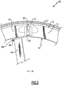
- a portion of the turbine section 28 is schematically illustrated and includes a turbine rotor blade 64 rotating relative to a radial surface 74 defined by a plurality of blade outer air seals (BOAS) 72.
- the turbine blade 64 includes a tip 66 that rotates proximate to the radial surface 74 defined by the BOAS 72.
- the example shown in Figure 2 is of a single, rotating turbine blade stage and may also be utilized within the compressor section 24.
- the BOAS 72 are supported within an engine case 62 with a mount 70.
- the mount 70 may be an integral part of the case 62 or may be a separate part attached to the case 62.
- a plurality of BOAS 72 form a full hoop circumferentially about the engine axis A to surround the blades 64.
- the BOAS 72 control leakage of core flow C in the gap 68 between the tips 66 and the inner surface 74.
- the illustrated mount 70 is disposed between each BOAS 72 and is one of a plurality of such mounts 70 disposed within the engine case 62.
- the gap 80 between each of the BOASs 72 is bridged by a feather seal 78 that is assembled between adjacent BOASs 72.
- each of the BOASs 72 are formed from a ceramic matrix composite material.
- CMC materials include a plurality of fibers suspended within a ceramic matrix.
- the fibers can, for example, be ceramic fibers, silicon fibers, carbon fibers, and or metallic fibers.
- the ceramic matrix material can be any known ceramic material such as silicon carbide.
- the ceramic matrix composite material provides the desired thermal capabilities to operate within the harsh environment of the turbine section 28.
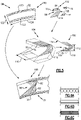
- the example BOAS 72 comprises a tube 82 with open ends 94 into which are assembled and mounted preforms 84.
- the tube 82 comprises an open structure having a substantially rectangular shape in cross-section.
- the preforms 84 define first and second slots 96 that correspond with a shape and contour of the mount 70.
- the example disclosed mount 70 includes outward extending arms 75 that fit within the slots 96 defined by the preforms 84.
- Each of the open ends 94 also includes a groove 90 for the feather seal 78.
- the open ends 94 each have a corresponding cutout 88 within the top surface 76 that is open the corresponding end 94.
- the cutouts 88 corresponds with a profile of the mount 70 such that the mount 70 may extend into the open ends 94 of the tube 82.
- the tube 82 may also include an opening 86 along the top surface 76 utilized to provide cooling air or to reduce the total weight of the BOAS 72.
- One or several openings 86 may be utilized and are within the contemplation of this disclosure.
- the preform 84 is formed separate from the tube 82 and assembled into each of the open ends 94.
- each BOAS 72 includes first and second open ends 94 that correspond with the mount 70 provided in the engine case 62.
- the preforms 84 are formed separately from the tube 82 and installed to define the slots 96 that correspond with the mount 70.
- Inserts 92 are provided along with each of the preforms 84 to support curved portions on a back side 85 of each preform 84.
- Each of the preforms 84 is formed from a plurality of fibers that substantially follow a contour of the desired slot 96.
- the slot 96 comprises a substantially c-shaped contour in cross-section that corresponds with arms 75 of the example mount 70. It should be appreciated that other shapes and contours could be utilized and are within the contemplation of this disclosure.
- the specific fit between the preform 84 and the arms 75 of the mount 70 are such that excessive movement is prevented while accommodating relative thermal expansion between the case 62, mount 70 and the BOASs 72.
- each of the BOASs 72 is designed and dimensioned to accommodate thermal expansion and movement relative to the rotating turbine blade 64.
- the method 98 includes an initial step 100 of forming the tube 82.
- the tube 82 will include a width 122 and a longitudinal length 124.
- a plurality of fibers will be included along the length 124 to provide the substantial structure of the tube 82.
- the example tube 82 is formed from a plurality of fibers 120 disposed within a ceramic matrix that are provided at a defined orientation.
- the desired orientation of the fibers 120 can be one orientation or a combination of orientations determined to provide the desired mechanical properties of the tube 82.
- the primary fibers 120 are orientated in a three dimensional braid.
- the primary fibers 120 are layered in a two-dimensional layers that extend substantially along the longitudinal length 124 of the tube 82.
- FIG. 6C a schematic view of another fiber orientation is illustrated and shows the primary fibers 120 orientated in a substantially three-dimensional woven mat that extends in the direction of the longitudinal length of the tube 82.
- formation of the preforms 84 is schematically illustrated at 102 and also includes formation of the inserts 92.
- Each of the preforms are formed with primary fibers 116 suspended in a ceramic matrix.
- the primary fibers 116 are orientated to follow a contour 118 that is utilized to define the slot 96.
- the fibers 116 substantially follow the contour 118 of the slot 96.
- the inserts 92 are formed from randomly orientated fibers or other compatible CMC material and fibers.
- the inserts 92 in this disclosed example are formed separate from the preforms 84 and are shaped to correspond with the back side 85 contour of the preform 84.
- the inserts 92 engage the back side 85 of the preform 84 to reduce and eliminate any unsupported region or area once installed into the tube 82.
- the example inserts 92 are disclosed as separate parts, formation of the preform 84 to include integral structures on the back side 85 for support could be utilized and are within the contemplation of this disclosure.
- the preforms 84 and inserts 92 can be formed using known CMC techniques including layering of a number of CMC sheets, polymer infiltration (PIP), chemical vapor infiltration (CVI) and chemical vapor deposition (CVD). In these processes the primary fibers are provided as a preform that is subsequently infiltrated with a ceramic matrix material.
- PIP polymer infiltration
- CVI chemical vapor infiltration
- CVD chemical vapor deposition
- Each of the preforms 84 are initially formed in a larger size than is required to fit within the tube 82. As is shown at 104, each of the preforms 84 is initially machined to provide a desired width 110. The primary fibers 116 are orientated to define the slot 96 and once the preform 84 is initially machined to provide a desired width as indicated at 110.
- the machining operation can include grinding, cutting or any other machining operations understood to be compatible with CMC materials.
- the height of the preform 84 is then adjusted to fit within the tube 82. All machining operations on the preform 84 are made with respect to a datum schematically indicated at 114 that corresponds with the mount structure 70. It is the slot 96 of the preform 84 that provides the origin to which all dimensions include the width 110, height 112 along with the shape of the slot 96 are orientated such that the installed preform 84 corresponds with the features of the mount 70.
- the preform 84 is installed within the tube 82 as schematically indicated at 108. Installation of the preform 84 into the end of the tube 82 defines the slots 96 within the completed BOAS 72. The preforms 84 are installed such that the slot 96 defined by the preform 84 corresponds with the open ends 94 and cut out 88 of the tube 82.
- Assembly of the preforms 84 and inserts 94 to the tube 82, 84 can be accomplished by any means understood known by those skilled in the art for adhesion of CMC materials to one another.
- the tube 82 and preform 84 are assembled in a partially cured condition and then fully cured together to provide a desired adhesion and structure.
- a ceramic matrix material is further infused into a partially cured tube 82, preform 84 and inserts 92 once assembled and finally cured to form one continuous structure.
- other known processes and methods of joining CMC parts could be utilized within the contemplation of this disclosure.
- the example BOAS 72 includes separately formed CMC components to form different structures for mounting and definition of the boundary surface to increase build quality, strength and durability.
Landscapes
- Engineering & Computer Science (AREA)
- Mechanical Engineering (AREA)
- General Engineering & Computer Science (AREA)
- Turbine Rotor Nozzle Sealing (AREA)
Applications Claiming Priority (2)
| Application Number | Priority Date | Filing Date | Title |
|---|---|---|---|
| US15/686,906 US10801349B2 (en) | 2017-08-25 | 2017-08-25 | Ceramic matrix composite blade outer air seal |
| EP18190807.0A EP3447252B1 (fr) | 2017-08-25 | 2018-08-24 | Joint d'étanchéité à l'air extérieur de lame composite à matrice céramique |
Related Parent Applications (1)
| Application Number | Title | Priority Date | Filing Date |
|---|---|---|---|
| EP18190807.0A Division EP3447252B1 (fr) | 2017-08-25 | 2018-08-24 | Joint d'étanchéité à l'air extérieur de lame composite à matrice céramique |
Publications (2)
| Publication Number | Publication Date |
|---|---|
| EP4006312A1 true EP4006312A1 (fr) | 2022-06-01 |
| EP4006312B1 EP4006312B1 (fr) | 2025-05-14 |
Family
ID=63405101
Family Applications (2)
| Application Number | Title | Priority Date | Filing Date |
|---|---|---|---|
| EP18190807.0A Active EP3447252B1 (fr) | 2017-08-25 | 2018-08-24 | Joint d'étanchéité à l'air extérieur de lame composite à matrice céramique |
| EP21215902.4A Active EP4006312B1 (fr) | 2017-08-25 | 2018-08-24 | Joint d'étanchéité à l'air extérieur de lame composite à matrice céramique |
Family Applications Before (1)
| Application Number | Title | Priority Date | Filing Date |
|---|---|---|---|
| EP18190807.0A Active EP3447252B1 (fr) | 2017-08-25 | 2018-08-24 | Joint d'étanchéité à l'air extérieur de lame composite à matrice céramique |
Country Status (2)
| Country | Link |
|---|---|
| US (2) | US10801349B2 (fr) |
| EP (2) | EP3447252B1 (fr) |
Families Citing this family (24)
| Publication number | Priority date | Publication date | Assignee | Title |
|---|---|---|---|---|
| US10934878B2 (en) * | 2018-12-05 | 2021-03-02 | Raytheon Technologies Corporation | CMC loop boas |
| US20200300107A1 (en) * | 2019-03-18 | 2020-09-24 | United Technologies Corporation | Cmc blade outer air seal |
| US11220924B2 (en) | 2019-09-26 | 2022-01-11 | Raytheon Technologies Corporation | Double box composite seal assembly with insert for gas turbine engine |
| US11359507B2 (en) | 2019-09-26 | 2022-06-14 | Raytheon Technologies Corporation | Double box composite seal assembly with fiber density arrangement for gas turbine engine |
| US11352897B2 (en) | 2019-09-26 | 2022-06-07 | Raytheon Technologies Corporation | Double box composite seal assembly for gas turbine engine |
| US11492733B2 (en) * | 2020-02-21 | 2022-11-08 | Raytheon Technologies Corporation | Weave control grid |
| US11619138B2 (en) * | 2021-04-30 | 2023-04-04 | Raytheon Technologies Corporation | Double brush seal assembly |
| US12320258B2 (en) * | 2022-11-18 | 2025-06-03 | Rtx Corporation | Blade outer air seal with large radius of curvature mount hooks |
| US12188365B1 (en) | 2023-12-04 | 2025-01-07 | Rolls-Royce Corporation | Method and apparatus for ceramic matrix composite turbine shroud assembly |
| US12286885B1 (en) | 2023-12-04 | 2025-04-29 | Rolls-Royce Corporation | Turbine assembly with confronting vane and turbine shroud segment |
| US12158072B1 (en) | 2023-12-04 | 2024-12-03 | Rolls-Royce Corporation | Turbine shroud segments with damping strip seals |
| US12286906B1 (en) | 2023-12-04 | 2025-04-29 | Rolls-Royce Corporation | Locating plate for use with turbine shroud assemblies |
| US12241376B1 (en) | 2023-12-04 | 2025-03-04 | Rolls-Royce Corporation | Locating plate for use with turbine shroud assemblies |
| US12152499B1 (en) | 2023-12-04 | 2024-11-26 | Rolls-Royce Corporation | Turbine shroud segments with strip seal assemblies having dampened ends |
| US12421862B2 (en) | 2023-12-04 | 2025-09-23 | Rolls-Royce Corporation | Turbine shroud assembly with angled cooling holes |
| US12421870B1 (en) | 2024-04-30 | 2025-09-23 | Rolls-Royce Corporation | Pin mounted ceramic matrix composite heat shields with impingement cooling |
| US12305525B1 (en) | 2024-05-30 | 2025-05-20 | Rolls-Royce Corporation | Turbine shroud assemblies with rod seal and strip seals |
| US12215593B1 (en) | 2024-05-30 | 2025-02-04 | Rolls-Royce Corporation | Turbine shroud assembly with inter-segment damping |
| US12258880B1 (en) | 2024-05-30 | 2025-03-25 | Rolls-Royce Corporation | Turbine shroud assemblies with inter-segment strip seal |
| US12416241B1 (en) | 2024-05-30 | 2025-09-16 | Rolls-Royce Corporation | Turbine shroud assemblies with strip seals |
| US12352176B1 (en) | 2024-05-31 | 2025-07-08 | Rolls-Royce Corporation | Turbine shroud assemblies with channels for buffer cavity seal thermal management |
| US12410725B1 (en) | 2024-05-31 | 2025-09-09 | Rolls-Royce Corporation | Turbine shroud assemblies with air activated pistons for biasing buffer cavity seals |
| US12577881B2 (en) | 2024-05-31 | 2026-03-17 | Rolls-Royce Corporation | Turbine shroud assemblies with anti-migration seals |
| US12228044B1 (en) | 2024-06-26 | 2025-02-18 | Rolls-Royce Corporation | Turbine shroud system with ceramic matrix composite segments and dual inter-segment seals |
Citations (3)
| Publication number | Priority date | Publication date | Assignee | Title |
|---|---|---|---|---|
| US20160215645A1 (en) * | 2013-08-29 | 2016-07-28 | United Technologies Corporation | Blade outer air seal made of ceramic matrix composite |
| US20160222828A1 (en) * | 2013-09-11 | 2016-08-04 | United Technologies Corporation | Blade outer air seal having angled retention hook |
| US20160319841A1 (en) * | 2013-12-17 | 2016-11-03 | United Technologies Corporation | Meter plate for blade outer air seal |
Family Cites Families (6)
| Publication number | Priority date | Publication date | Assignee | Title |
|---|---|---|---|---|
| US6733235B2 (en) | 2002-03-28 | 2004-05-11 | General Electric Company | Shroud segment and assembly for a turbine engine |
| US8303247B2 (en) | 2007-09-06 | 2012-11-06 | United Technologies Corporation | Blade outer air seal |
| US8790067B2 (en) * | 2011-04-27 | 2014-07-29 | United Technologies Corporation | Blade clearance control using high-CTE and low-CTE ring members |
| GB201305702D0 (en) | 2013-03-28 | 2013-05-15 | Rolls Royce Plc | Seal segment |
| US10370997B2 (en) | 2015-05-26 | 2019-08-06 | Rolls-Royce Corporation | Turbine shroud having ceramic matrix composite seal segment |
| US10385718B2 (en) | 2015-06-29 | 2019-08-20 | Rolls-Royce North American Technologies, Inc. | Turbine shroud segment with side perimeter seal |
-
2017
- 2017-08-25 US US15/686,906 patent/US10801349B2/en active Active
-
2018
- 2018-08-24 EP EP18190807.0A patent/EP3447252B1/fr active Active
- 2018-08-24 EP EP21215902.4A patent/EP4006312B1/fr active Active
-
2020
- 2020-10-09 US US17/066,865 patent/US20210025285A1/en not_active Abandoned
Patent Citations (3)
| Publication number | Priority date | Publication date | Assignee | Title |
|---|---|---|---|---|
| US20160215645A1 (en) * | 2013-08-29 | 2016-07-28 | United Technologies Corporation | Blade outer air seal made of ceramic matrix composite |
| US20160222828A1 (en) * | 2013-09-11 | 2016-08-04 | United Technologies Corporation | Blade outer air seal having angled retention hook |
| US20160319841A1 (en) * | 2013-12-17 | 2016-11-03 | United Technologies Corporation | Meter plate for blade outer air seal |
Also Published As
| Publication number | Publication date |
|---|---|
| EP4006312B1 (fr) | 2025-05-14 |
| EP3447252B1 (fr) | 2021-12-29 |
| EP3447252A1 (fr) | 2019-02-27 |
| US20190063249A1 (en) | 2019-02-28 |
| US10801349B2 (en) | 2020-10-13 |
| US20210025285A1 (en) | 2021-01-28 |
Similar Documents
| Publication | Publication Date | Title |
|---|---|---|
| EP3447252B1 (fr) | Joint d'étanchéité à l'air extérieur de lame composite à matrice céramique | |
| EP3792453B1 (fr) | Ensemble boas cmc | |
| EP3819475B1 (fr) | Agencement de joint d'air extérieur d'aube et procédé d'étanchéité | |
| EP3667029B1 (fr) | Ensemble d'étanchéité d'un moteur à turbine à gaz comportant un insert d'usure ductile | |
| EP3892824B1 (fr) | Broche de fixation pour composants de cmc dans un moteur à turbine à gaz | |
| EP4056811A1 (fr) | Agencement de joint de surface d'accouplement avec rainures pour plateformes cmc | |
| EP3819477A1 (fr) | Agencement d'encoche de joint à languette destiné à un ensemble virole d'étanchéité extérieur d'aubes en cmc | |
| EP4219909B1 (fr) | Ensemble joint d'étanchéité composite à double boîte avec insert pour moteur à turbine à gaz | |
| EP3739168B1 (fr) | Agencement d'un virole d'une turbine á gaz et procédé | |
| EP3798420B1 (fr) | Ensemble joint composite à double boîtier pour moteur à turbine à gaz, moteur à turbine à gaz et procédé | |
| EP4219908B1 (fr) | Ensemble joint d'étanchéité composite à double boîte avec agencement de densité de fibres pour moteur à turbine à gaz | |
| EP3767076B1 (fr) | Ensemble avec joint d'air extérieur d'aube en composite à matrice céramique | |
| EP3722569B1 (fr) | Joint d'étanchéité à l'air extérieur d'aubes et section de turbine | |
| EP3767075A1 (fr) | Ensemble avec joint d'air extérieur d'aube en composite à matrice céramique | |
| EP3767077B1 (fr) | Agencement boas cmc | |
| EP3636885B1 (fr) | Section de turbine pour moteur à turbine à gaz et procédé de fabrication d'un joint à l'air extérieur d'aubes | |
| EP3767078A1 (fr) | Agencement boas cmc | |
| EP3760836B1 (fr) | Anneau de turbine avec double boîte et dispositif de maintien | |
| EP3819476B1 (fr) | Ensemble de boas pour une turbine á gaz | |
| EP4056812A1 (fr) | Joint rainurée à chevrons |
Legal Events
| Date | Code | Title | Description |
|---|---|---|---|
| PUAI | Public reference made under article 153(3) epc to a published international application that has entered the european phase |
Free format text: ORIGINAL CODE: 0009012 |
|
| STAA | Information on the status of an ep patent application or granted ep patent |
Free format text: STATUS: THE APPLICATION HAS BEEN PUBLISHED |
|
| AC | Divisional application: reference to earlier application |
Ref document number: 3447252 Country of ref document: EP Kind code of ref document: P |
|
| AK | Designated contracting states |
Kind code of ref document: A1 Designated state(s): AL AT BE BG CH CY CZ DE DK EE ES FI FR GB GR HR HU IE IS IT LI LT LU LV MC MK MT NL NO PL PT RO RS SE SI SK SM TR |
|
| STAA | Information on the status of an ep patent application or granted ep patent |
Free format text: STATUS: REQUEST FOR EXAMINATION WAS MADE |
|
| 17P | Request for examination filed |
Effective date: 20221201 |
|
| RBV | Designated contracting states (corrected) |
Designated state(s): AL AT BE BG CH CY CZ DE DK EE ES FI FR GB GR HR HU IE IS IT LI LT LU LV MC MK MT NL NO PL PT RO RS SE SI SK SM TR |
|
| STAA | Information on the status of an ep patent application or granted ep patent |
Free format text: STATUS: EXAMINATION IS IN PROGRESS |
|
| 17Q | First examination report despatched |
Effective date: 20230913 |
|
| RAP3 | Party data changed (applicant data changed or rights of an application transferred) |
Owner name: RTX CORPORATION |
|
| GRAP | Despatch of communication of intention to grant a patent |
Free format text: ORIGINAL CODE: EPIDOSNIGR1 |
|
| STAA | Information on the status of an ep patent application or granted ep patent |
Free format text: STATUS: GRANT OF PATENT IS INTENDED |
|
| INTG | Intention to grant announced |
Effective date: 20241203 |
|
| GRAS | Grant fee paid |
Free format text: ORIGINAL CODE: EPIDOSNIGR3 |
|
| GRAA | (expected) grant |
Free format text: ORIGINAL CODE: 0009210 |
|
| STAA | Information on the status of an ep patent application or granted ep patent |
Free format text: STATUS: THE PATENT HAS BEEN GRANTED |
|
| AC | Divisional application: reference to earlier application |
Ref document number: 3447252 Country of ref document: EP Kind code of ref document: P |
|
| AK | Designated contracting states |
Kind code of ref document: B1 Designated state(s): AL AT BE BG CH CY CZ DE DK EE ES FI FR GB GR HR HU IE IS IT LI LT LU LV MC MK MT NL NO PL PT RO RS SE SI SK SM TR |
|
| REG | Reference to a national code |
Ref country code: GB Ref legal event code: FG4D |
|
| REG | Reference to a national code |
Ref country code: CH Ref legal event code: EP |
|
| REG | Reference to a national code |
Ref country code: IE Ref legal event code: FG4D |
|
| REG | Reference to a national code |
Ref country code: DE Ref legal event code: R096 Ref document number: 602018082041 Country of ref document: DE |
|
| REG | Reference to a national code |
Ref country code: NL Ref legal event code: MP Effective date: 20250514 |
|
| PG25 | Lapsed in a contracting state [announced via postgrant information from national office to epo] |
Ref country code: PT Free format text: LAPSE BECAUSE OF FAILURE TO SUBMIT A TRANSLATION OF THE DESCRIPTION OR TO PAY THE FEE WITHIN THE PRESCRIBED TIME-LIMIT Effective date: 20250915 Ref country code: FI Free format text: LAPSE BECAUSE OF FAILURE TO SUBMIT A TRANSLATION OF THE DESCRIPTION OR TO PAY THE FEE WITHIN THE PRESCRIBED TIME-LIMIT Effective date: 20250514 Ref country code: ES Free format text: LAPSE BECAUSE OF FAILURE TO SUBMIT A TRANSLATION OF THE DESCRIPTION OR TO PAY THE FEE WITHIN THE PRESCRIBED TIME-LIMIT Effective date: 20250514 |
|
| PGFP | Annual fee paid to national office [announced via postgrant information from national office to epo] |
Ref country code: DE Payment date: 20250724 Year of fee payment: 8 |
|
| REG | Reference to a national code |
Ref country code: LT Ref legal event code: MG9D |
|
| PG25 | Lapsed in a contracting state [announced via postgrant information from national office to epo] |
Ref country code: NO Free format text: LAPSE BECAUSE OF FAILURE TO SUBMIT A TRANSLATION OF THE DESCRIPTION OR TO PAY THE FEE WITHIN THE PRESCRIBED TIME-LIMIT Effective date: 20250814 Ref country code: GR Free format text: LAPSE BECAUSE OF FAILURE TO SUBMIT A TRANSLATION OF THE DESCRIPTION OR TO PAY THE FEE WITHIN THE PRESCRIBED TIME-LIMIT Effective date: 20250815 |
|
| PG25 | Lapsed in a contracting state [announced via postgrant information from national office to epo] |
Ref country code: NL Free format text: LAPSE BECAUSE OF FAILURE TO SUBMIT A TRANSLATION OF THE DESCRIPTION OR TO PAY THE FEE WITHIN THE PRESCRIBED TIME-LIMIT Effective date: 20250514 Ref country code: PL Free format text: LAPSE BECAUSE OF FAILURE TO SUBMIT A TRANSLATION OF THE DESCRIPTION OR TO PAY THE FEE WITHIN THE PRESCRIBED TIME-LIMIT Effective date: 20250514 |
|
| REG | Reference to a national code |
Ref country code: AT Ref legal event code: MK05 Ref document number: 1794919 Country of ref document: AT Kind code of ref document: T Effective date: 20250514 |
|
| PG25 | Lapsed in a contracting state [announced via postgrant information from national office to epo] |
Ref country code: BG Free format text: LAPSE BECAUSE OF FAILURE TO SUBMIT A TRANSLATION OF THE DESCRIPTION OR TO PAY THE FEE WITHIN THE PRESCRIBED TIME-LIMIT Effective date: 20250514 |
|
| PGFP | Annual fee paid to national office [announced via postgrant information from national office to epo] |
Ref country code: GB Payment date: 20250725 Year of fee payment: 8 |
|
| PG25 | Lapsed in a contracting state [announced via postgrant information from national office to epo] |
Ref country code: HR Free format text: LAPSE BECAUSE OF FAILURE TO SUBMIT A TRANSLATION OF THE DESCRIPTION OR TO PAY THE FEE WITHIN THE PRESCRIBED TIME-LIMIT Effective date: 20250514 |
|
| PG25 | Lapsed in a contracting state [announced via postgrant information from national office to epo] |
Ref country code: AT Free format text: LAPSE BECAUSE OF FAILURE TO SUBMIT A TRANSLATION OF THE DESCRIPTION OR TO PAY THE FEE WITHIN THE PRESCRIBED TIME-LIMIT Effective date: 20250514 |
|
| PGFP | Annual fee paid to national office [announced via postgrant information from national office to epo] |
Ref country code: FR Payment date: 20250725 Year of fee payment: 8 |
|
| PG25 | Lapsed in a contracting state [announced via postgrant information from national office to epo] |
Ref country code: RS Free format text: LAPSE BECAUSE OF FAILURE TO SUBMIT A TRANSLATION OF THE DESCRIPTION OR TO PAY THE FEE WITHIN THE PRESCRIBED TIME-LIMIT Effective date: 20250814 |
|
| PG25 | Lapsed in a contracting state [announced via postgrant information from national office to epo] |
Ref country code: IS Free format text: LAPSE BECAUSE OF FAILURE TO SUBMIT A TRANSLATION OF THE DESCRIPTION OR TO PAY THE FEE WITHIN THE PRESCRIBED TIME-LIMIT Effective date: 20250914 |
|
| PG25 | Lapsed in a contracting state [announced via postgrant information from national office to epo] |
Ref country code: LV Free format text: LAPSE BECAUSE OF FAILURE TO SUBMIT A TRANSLATION OF THE DESCRIPTION OR TO PAY THE FEE WITHIN THE PRESCRIBED TIME-LIMIT Effective date: 20250514 |
|
| PG25 | Lapsed in a contracting state [announced via postgrant information from national office to epo] |
Ref country code: DK Free format text: LAPSE BECAUSE OF FAILURE TO SUBMIT A TRANSLATION OF THE DESCRIPTION OR TO PAY THE FEE WITHIN THE PRESCRIBED TIME-LIMIT Effective date: 20250514 Ref country code: SM Free format text: LAPSE BECAUSE OF FAILURE TO SUBMIT A TRANSLATION OF THE DESCRIPTION OR TO PAY THE FEE WITHIN THE PRESCRIBED TIME-LIMIT Effective date: 20250514 |
|
| PG25 | Lapsed in a contracting state [announced via postgrant information from national office to epo] |
Ref country code: CZ Free format text: LAPSE BECAUSE OF FAILURE TO SUBMIT A TRANSLATION OF THE DESCRIPTION OR TO PAY THE FEE WITHIN THE PRESCRIBED TIME-LIMIT Effective date: 20250514 |
|
| PG25 | Lapsed in a contracting state [announced via postgrant information from national office to epo] |
Ref country code: EE Free format text: LAPSE BECAUSE OF FAILURE TO SUBMIT A TRANSLATION OF THE DESCRIPTION OR TO PAY THE FEE WITHIN THE PRESCRIBED TIME-LIMIT Effective date: 20250514 |
|
| PG25 | Lapsed in a contracting state [announced via postgrant information from national office to epo] |
Ref country code: RO Free format text: LAPSE BECAUSE OF FAILURE TO SUBMIT A TRANSLATION OF THE DESCRIPTION OR TO PAY THE FEE WITHIN THE PRESCRIBED TIME-LIMIT Effective date: 20250514 Ref country code: SK Free format text: LAPSE BECAUSE OF FAILURE TO SUBMIT A TRANSLATION OF THE DESCRIPTION OR TO PAY THE FEE WITHIN THE PRESCRIBED TIME-LIMIT Effective date: 20250514 |
|
| PG25 | Lapsed in a contracting state [announced via postgrant information from national office to epo] |
Ref country code: IT Free format text: LAPSE BECAUSE OF FAILURE TO SUBMIT A TRANSLATION OF THE DESCRIPTION OR TO PAY THE FEE WITHIN THE PRESCRIBED TIME-LIMIT Effective date: 20250514 |
|
| REG | Reference to a national code |
Ref country code: DE Ref legal event code: R097 Ref document number: 602018082041 Country of ref document: DE |
|
| PLBE | No opposition filed within time limit |
Free format text: ORIGINAL CODE: 0009261 |
|
| STAA | Information on the status of an ep patent application or granted ep patent |
Free format text: STATUS: NO OPPOSITION FILED WITHIN TIME LIMIT |
|
| REG | Reference to a national code |
Ref country code: CH Ref legal event code: H13 Free format text: ST27 STATUS EVENT CODE: U-0-0-H10-H13 (AS PROVIDED BY THE NATIONAL OFFICE) Effective date: 20260324 |
|
| REG | Reference to a national code |
Ref country code: CH Ref legal event code: L10 Free format text: ST27 STATUS EVENT CODE: U-0-0-L10-L00 (AS PROVIDED BY THE NATIONAL OFFICE) Effective date: 20260325 |
|
| PG25 | Lapsed in a contracting state [announced via postgrant information from national office to epo] |
Ref country code: MC Free format text: LAPSE BECAUSE OF FAILURE TO SUBMIT A TRANSLATION OF THE DESCRIPTION OR TO PAY THE FEE WITHIN THE PRESCRIBED TIME-LIMIT Effective date: 20250514 |
|
| PG25 | Lapsed in a contracting state [announced via postgrant information from national office to epo] |
Ref country code: LU Free format text: LAPSE BECAUSE OF NON-PAYMENT OF DUE FEES Effective date: 20250824 |
|
| 26N | No opposition filed |
Effective date: 20260217 |
|
| PG25 | Lapsed in a contracting state [announced via postgrant information from national office to epo] |
Ref country code: CH Free format text: LAPSE BECAUSE OF NON-PAYMENT OF DUE FEES Effective date: 20250831 |