EP4006325B1 - Generatorkühlsystem eines turbofantriebs - Google Patents
Generatorkühlsystem eines turbofantriebs Download PDFInfo
- Publication number
- EP4006325B1 EP4006325B1 EP20844627.8A EP20844627A EP4006325B1 EP 4006325 B1 EP4006325 B1 EP 4006325B1 EP 20844627 A EP20844627 A EP 20844627A EP 4006325 B1 EP4006325 B1 EP 4006325B1
- Authority
- EP
- European Patent Office
- Prior art keywords
- generator
- air
- air duct
- electric power
- fan
- Prior art date
- Legal status (The legal status is an assumption and is not a legal conclusion. Google has not performed a legal analysis and makes no representation as to the accuracy of the status listed.)
- Active
Links
Images

Classifications
-
- H—ELECTRICITY
- H02—GENERATION; CONVERSION OR DISTRIBUTION OF ELECTRIC POWER
- H02K—DYNAMO-ELECTRIC MACHINES
- H02K7/00—Arrangements for handling mechanical energy structurally associated with dynamo-electric machines, e.g. structural association with mechanical driving motors or auxiliary dynamo-electric machines
- H02K7/18—Structural association of electric generators with mechanical driving motors, e.g. with turbines
- H02K7/1807—Rotary generators
- H02K7/1823—Rotary generators structurally associated with turbines or similar engines
-
- F—MECHANICAL ENGINEERING; LIGHTING; HEATING; WEAPONS; BLASTING
- F02—COMBUSTION ENGINES; HOT-GAS OR COMBUSTION-PRODUCT ENGINE PLANTS
- F02C—GAS-TURBINE PLANTS; AIR INTAKES FOR JET-PROPULSION PLANTS; CONTROLLING FUEL SUPPLY IN AIR-BREATHING JET-PROPULSION PLANTS
- F02C7/00—Features, components parts, details or accessories, not provided for in, or of interest apart form groups F02C1/00 - F02C6/00; Air intakes for jet-propulsion plants
- F02C7/12—Cooling of plants
- F02C7/16—Cooling of plants characterised by cooling medium
- F02C7/18—Cooling of plants characterised by cooling medium the medium being gaseous, e.g. air
-
- H—ELECTRICITY
- H02—GENERATION; CONVERSION OR DISTRIBUTION OF ELECTRIC POWER
- H02K—DYNAMO-ELECTRIC MACHINES
- H02K5/00—Casings; Enclosures; Supports
- H02K5/04—Casings or enclosures characterised by the shape, form or construction thereof
- H02K5/22—Auxiliary parts of casings not covered by groups H02K5/06-H02K5/20, e.g. shaped to form connection boxes or terminal boxes
- H02K5/225—Terminal boxes or connection arrangements
-
- H—ELECTRICITY
- H02—GENERATION; CONVERSION OR DISTRIBUTION OF ELECTRIC POWER
- H02K—DYNAMO-ELECTRIC MACHINES
- H02K9/00—Arrangements for cooling or ventilating
- H02K9/02—Arrangements for cooling or ventilating by ambient air flowing through the machine
-
- F—MECHANICAL ENGINEERING; LIGHTING; HEATING; WEAPONS; BLASTING
- F05—INDEXING SCHEMES RELATING TO ENGINES OR PUMPS IN VARIOUS SUBCLASSES OF CLASSES F01-F04
- F05D—INDEXING SCHEME FOR ASPECTS RELATING TO NON-POSITIVE-DISPLACEMENT MACHINES OR ENGINES, GAS-TURBINES OR JET-PROPULSION PLANTS
- F05D2220/00—Application
- F05D2220/70—Application in combination with
- F05D2220/76—Application in combination with an electrical generator
-
- F—MECHANICAL ENGINEERING; LIGHTING; HEATING; WEAPONS; BLASTING
- F05—INDEXING SCHEMES RELATING TO ENGINES OR PUMPS IN VARIOUS SUBCLASSES OF CLASSES F01-F04
- F05D—INDEXING SCHEME FOR ASPECTS RELATING TO NON-POSITIVE-DISPLACEMENT MACHINES OR ENGINES, GAS-TURBINES OR JET-PROPULSION PLANTS
- F05D2260/00—Function
- F05D2260/20—Heat transfer, e.g. cooling
- F05D2260/234—Heat transfer, e.g. cooling of the generator by compressor inlet air
Definitions
- Embodiments described herein relates to a system for cooling a generator and an electric power cable connected to the generator, the generator and the electric power cable being disposed in a hot section of a turbo-fan engine.
- a turbo-fan engine is composed of a fan disposed at a frontmost portion and a core engine disposed coaxially with the fan behind the fan.
- a core engine includes a low pressure compressor, a high pressure compressor, a combustor, a high pressure turbine, and a low pressure turbine in this order from a front portion (upstream) to a rear portion (downstream), a rotor of the high pressure turbine drives and rotates a rotor of the high pressure compressor via a high pressure shaft, and a rotor of the low pressure turbine drives and rotates rotors of the low pressure compressor and the fan via a low pressure shaft respectively.
- Both the high pressure and low pressure shafts are hollow shafts, and the low pressure shaft is disposed inside the high pressure shaft.
- a part of air suctioned by the fan and then compressed during an operation of the turbo-fan engine flows into the core engine and contributes to generation of high-temperature and high-pressure gas for driving the low pressure turbine, which is a rotation drive source of the fan and the low pressure compressor, and a remaining part of the air bypasses the core engine, is then discharged from the rear side, and contributes to generation of a most part of a thrust.
- a turbo-fan engine mounted on an aircraft includes a generator driven by power extracted from main shafts in order to supply electric power to electric and electronic devices mounted on the aircraft body in addition to an engine control device.
- a turbo-fan engine in the related art, power is extracted from a high pressure shaft via a power take-off (PTO) shaft provided inside a front frame disposed at a front portion and is transmitted to a generator attached to an accessor gear box (AGB) disposed in the vicinity of the front frame (for example, outside a casing of a fan, inside a core cowl surrounding a core engine (outside a casing of a high pressure compressor), or the like) via the AGB.
- PTO power take-off
- AGB accessor gear box
- a generator (electric machine (32)) that is driven by a low pressure shaft (low pressure shaft (24)) via a coupling mechanism (coupling mechanism (44)) is disposed inside a tail cone (tail cone (30)) attached to a support structure (support structure (42)) such as a turbine exhaust case (see FIG. 2 ).
- the tail cone is located in a hot section (a combustor and a portion further downstream than the combustor) of the turbo-fan engine, and the inside of the tail cone is heated to a high temperature due to an influence of turbine exhaust (typically, about 600°C at maximum) flowing in the surroundings. Therefore, the inside of the tail cone is required to be cooled in order to protect the generator disposed in the tail cone from damage due to overheating.
- the tail cone is provided with a cooling fluid inlet (cooling fluid inlet (46)) and a cooling fluid outlet (cooling fluid outlet (48)) such that the inside of the tail cone is cooled through circulation of a cooling fluid such as air.
- Patent Document 1 does not include any mention regarding a supply source for air as the aforementioned cooling fluid
- the supply source is to be a portion of a mainstream flow path (a flow path of air that is a working fluid) in the turbo-fan engine from which part air at a temperature that does not exceed an upper limit temperature (about 200°C, for example) for utilization of the generator can be extracted regardless of a rating of the engine.
- Examples of such a portion include a fan outlet (more strictly, a trailing edge of a fan exit guide vane).
- US 2018/134407 A1 discloses a system for cooling regions within a turbofan engine.
- US 2018/051702 A1 discloses a system for cooling a generator and an electric power cable connected to the generator.
- the generator and the electric power cable are disposed in a hot section of a turbo-fan engine.
- the system comprises a junction box, a cooling fluid air duct that extends from the junction box to a space in which the generator is accommodated and accommodates the electric power cable inside the cooling fluid air duct.
- Patent Document 1 U.S. Patent No. 9,003,811
- air extracted from the fan outlet of the turbo-fan engine though having a sufficiently low temperature as described above, has a low pressure in a case in which the rating of the engine is low (idle, for example), and a sufficient flow amount of air cannot be supplied due to a pressure loss in a supply path to the inside of the tail cone.
- turbine exhaust has a temperature exceeding the upper limit temperature for utilization of the generator even in a case in which the rating of the engine is low, and there is a concern that the generator may be overheated and damaged due to insufficient flow amount of the cooling air supplied to the inside of the tail cone.
- the present disclosure was made in view of the aforementioned circumstances, and an object of the present disclosure is to provide a system capable of appropriately cooling a generator and an electric power cable connected to the generator with the generator and the electric power cable being disposed in a hot section of a turbo-fan engine, regardless of a rating of an engine.
- an aspect of the present disclosure is directed to a system including: a junction box; a bypass air duct that supplies, to the junction box, air extracted from a portion of a bypass flow path of a turbo-fan engine on a side further downstream than a fan outlet; a core air duct that supplies, to the junction box, air extracted from a portion of a core flow path of the turbo-fan engine on a side further upstream than a compressor outlet; and a cooling air duct that extends from the junction box to a space in which the generator is accommodated and accommodates the electric power cable inside the cooling air duct, and valves that are able to be independently controlled to open and close are provided at downstream ends of the bypass air duct and the core air duct.
- an excellent advantage that it is possible to appropriately cool a generator and an electric power cable connected to the generator with the generator and the electric power cable being disposed in a hot section of a turbo-fan engine, regardless of a rating of an engine can be achieved.
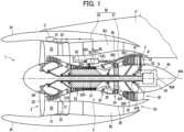
- FIG. 1 is a schematic sectional view of a turbo-fan engine 1 that employs a system according to an embodiment of the present disclosure.
- the turbo-fan engine 1 is composed of a fan 2 disposed at a frontmost portion and a core engine 3 disposed coaxially with the fan 2 behind the fan 2.
- the fan 2 incudes a substantially cylindrical fan case 21, a fan rotor (fan disk) 2R rotatably supported inside the fan case 21, a plurality of fan blades (rotor blades) 22 attached at equal intervals to an outer periphery of the fan rotor 2R in a circumferential direction, and a plurality of fan exit guide vanes (stator vanes) 23 attached at equal intervals to a bypass flow path 20, which will be described later, in the circumferential direction.
- the fan case 21 is surrounded by a substantially cylindrical nacelle 24, and the nacelle 24 is coupled to a main wing (not illustrated) of an aircraft, which mounts the turbo-fan engine 1, via a pylon P.
- the core engine 3 is surrounded by a substantially cylindrical core cowl 38, and the core cowl 38 is coupled to the nacelle 24 via an upper bifurcation BU and a lower bifurcation BL that are hollow pillars with streamlined sections.
- the core engine 3 includes a low pressure compressor 31, a high pressure compressor 32, a combustor 33, a high pressure turbine 34, and a low pressure turbine 35 in this order from the front portion (upstream) to the rear portion (downstream), a rotor 34R of the high pressure turbine 34 drives and rotates a rotor 32R of the high pressure compressor 32 via a high pressure shaft 36, and a rotor 35R of the low pressure turbine 35 drives and rotates a rotor 2R of the fan 2 and a rotor 31R of the low pressure compressor 31 via a low pressure shaft 37 respectively.
- both the high pressure shaft 36 and the low pressure shaft 37 are hollow shafts and the low pressure shaft 37 is disposed inside the high pressure shaft 36.
- a turbine exhaust frame 4 that rotatably supports a rear end portion of the low pressure shaft 37 via a bearing 37B is disposed behind the low pressure turbine 35.
- the turbine exhaust frame 4 includes an annular outer ring 41 on an outer side in a radial direction and an annular inner ring 42 on an inner side in the radial direction, and both the rings are coupled to each other with a plurality of hollow struts (pillars) 43 disposed at equal intervals in the circumferential direction.
- the outer ring 41 is coupled, at a front end, to a casing 35C of the low pressure turbine 35, and the inner ring 42 supports, at a rear end, a substantially conical-shaped tail cone 44. At least a part of the tail cone 44 defines a boundary of a flow path of a core nozzle 39, which will be described later, in an inner side in the radial direction.
- the air that has flowed into the core flow path 30 is successively compressed by the low pressure compressor 31 and the high pressure compressor 32 and then flows into the combustor 33.
- Combustion gas generated through combustion of a fuel in the combustor 33 is successively expanded by the high pressure turbine 34 and the low pressure turbine 35 and is then discharged through the core nozzle 39.
- a static pressure of the air that has flowed into the bypass flow path 20 is recovered, and swirl velocity components are removed from the air, when the air passing through the fan exit guide vane 23, and the air is discharged through a bypass nozzle 25 and contributes to generation of a most part of a thrust.
- a generator G is disposed inside the tail cone 44. More strictly, the generator G is disposed inside a heat shield 45 to block radiant heat inputs from the tail cone 44 heated by the turbine exhaust. Note that a tail cone exhaust hole 44A and a heat shield exhaust hole 45A are provided at rear end portions of the tail cone 44 and the heat shield 45 in order to discharge the cooling air supplied through cooling air ducts 61, which will be described later.
- An input shaft of the generator G is coupled to a rear end of the low pressure shaft 37 and is driven and rotated by the low pressure shaft 37. Note that the input shaft of the generator G and the low pressure shaft 37 may be coupled directly to each other or may be coupled to each other via a coupling mechanism.
- a converter C is disposed at an outer periphery of the fan case 21 inside the nacelle 24, and the generator G and the converter C are connected to each other via electric power cables 50.
- the generator G is formed to cause a three-phase AC to be generated, and the generator G and the converter C are connected to each other via three electric power cables 50 corresponding to the phases (only one electric power cable 50 is illustrated in the drawing).
- the electric power cables 50 include electric power cables 51 extending from the inside of the tail cone 44, in which the generator G is disposed, enter the space inside the core cowl 38 through the inside of the hollow struts 43 of the turbine exhaust frame 4, successively pass through the outer periphery of the casing 35C of the low pressure turbine 35, the outer periphery of a casing 34C of the high pressure turbine 34, and the outer periphery of a casing 33C of the combustor 33, and reach a junction box 60, which will be described later, and electric power cables 52 that enter the space inside the nacelle 24 from the junction box 60 through the inside of the hollow upper bifurcation BU and reach the converter C, although the components are schematically illustrated in FIG. 1 .
- the electric power cables 51 are laid in a hot section (relatively high-temperature portion located at the combustor 33 and further downstream than the combustor 33) of the turbo-fan engine 1, the electric power cables 51 will be referred to as high-temperature part electric power cables 51 below. Also, since the electric power cables 52 are laid in a cold section (relatively low-temperature portion other than the hot section) of the turbo-fan engine 1, the electric power cables 52 will be referred to as low-temperature part electric power cables 52 below.
- the high-temperature part electric power cables 51 are laid in the hot section of the turbo-fan engine 1 as described above, the high-temperature part electric power cables 51 are heated by heat inputs from the casing 35C of the low pressure turbine 35, the casing 34C of the high pressure turbine 34, and the casing 33c of the combustor 33, and generate a large amount of heat with feeding of a large current, the high-temperature part electric power cables 51 are to be appropriately cooled. Moreover, since the generator G disposed inside the tail cone 44 is also heated to a high temperature due to influences of turbine exhaust passing through the core nozzle 39, the generator G is to be appropriately cooled.
- the system according to the embodiment of the present disclosure is provided with the cooling air ducts 61 to supply the cooling air into the tail cone 44, and the high-temperature part electric power cables 51 are accommodated inside the cooling air ducts 61.
- the cooling air ducts 61 reach an outer periphery of the turbine exhaust frame 4 from the junction box 60 disposed at an outer periphery of the casing 32C of the high pressure compressor 32 (cold section) and through an outer periphery of the casing 33C of the combustor 33, an outer periphery of the casing 34C of the high pressure turbine 34, and an outer periphery of the casing 35C of the low pressure turbine 35 in order and reach the inside of the heat shield 45 inside the tail cone 44 through the inside of the hollow struts 43 of the turbine exhaust frame 4.
- a bypass air duct 62 to extract air (fan outlet air or bypass air) from a portion of the bypass flow path 20 on a side further downstream than the fan outlet (more specifically, the trailing edge of the fan exit guide vane 23) and supply the air to the junction box 60 and a core air duct 63 to extract air (core air) from a part of the core flow path 30 on a side further upstream than the outlet of the high pressure compressor 32 and supply the air to the junction box 60 are connected to the junction box 60.
- a bypass air ON/OFF valve 62V and a core air ON/OFF valve 63V that can be mutually independently controlled to open and close are disposed at downstream ends (portion on a side immediately upstream the parts of connection to the junction box 60) of the bypass air duct 62 and the core air duct 63, respectively.
- the ON/OFF valves 62V and 63V are controlled such that one of the ON/OFF valves 62V and 63V is opened (ON state) while the other is closed (OFF state) in accordance with an operating condition of the turbo-fan engine 1 as will be described later.
- the core air duct 63 is connected to an air bleed port (not illustrated) provided at a portion of the casings of the compressors (the low pressure compressor 31 and the high pressure compressor 32) located on a side further upstream than the outlet of the high pressure compressor 32, and the core air is extracted via the air bleed port.
- the portion at which the air bleed port is provided is a portion at which the core air supplied to the cooling air ducts 61 from the air bleed port through the junction box 60 satisfies the requirements (a pressure and a temperature) to keep the generator G and the high-temperature part electric power cables 51 at or below an acceptable upper limit temperature under the operating condition of the core air ON/OFF valve 63V being opened.
- the air bleed port is preferably provided on a side further upstream to extract air at a lower temperature while the air bleed port is preferably provided at a side further downstream to extract a larger flow amount of air (against a duct resistance of the core air duct 63 and the cooling air ducts 61), the portion at which the air bleed port is provided is determined on the basis of trade-off between these conditions.
- FIG. 2 is a partially broken perspective view illustrating a structure of the junction box 60 in the system according to the embodiment of the present disclosure.
- the junction box 60 includes a hollow case body 64 with a combination shape of an isosceles trapezoid (front portion) and a rectangle (rear portion) in a plan view, distribution plates 65 disposed inside the case body 64, and low-temperature part electric power cable guidance ports 66 disposed on an upper wall 64U of the case body 64.
- a front wall 64F and a lower wall 64L of the case body 64 are provided with through-holes respectively, and the bypass air ON/OFF valve 62V and the core air ON/OFF valve 63V described above are connected to the through-holes.
- three through-holes are provided in a rear wall 64R of the case body 64, and three cooling air ducts 61 are connected to the through-holes.
- one high-temperature part electric power cable 51 is accommodated inside each cooling air duct 61.
- the total of three high-temperature part electric power cables 51 are provided to correspond to the phases of the three-phase AC generated by the generator G.
- the three high-temperature part electric power cables 51 are configured as bus bars obtained by applying insulating coating to bars made of copper to meet the need to supply a large current from the generator G to the converter C.
- Three low-temperature part electric power cables 52 are guided from the low-temperature part electric power cable guidance ports 66 disposed on the upper wall 64U of the case body 64 to correspond to the aforementioned three high-temperature part electric power cables 51.
- the high-temperature part electric power cable 51 and the low-temperature part electric power cable 52 of each phase of the three-phase AC are connected to each other inside the case body 64 of the junction box 60 although not illustrated in the drawing. Note that both the electric power cables may be connected directly to each other or may be connected via a terminal board disposed inside the case body 64.
- the bypass air (fan outlet air) or the core air flows into the junction box 60 through either the bypass air ON/OFF valve 62V or the core air ON/OFF valve 63V as will be described later, and two distribution plates 65 are disposed inside the case body 64 in order to uniformly distribute the air that has flowed into the junction box 60 to the three cooling air ducts 61.
- the distribution plates 65 extend from the rear wall 64R toward the front wall 64F inside the case body 64 and up to the vicinity of the through-hole to which the core air ON/OFF valve 63V is connected.
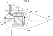
- FIG. 3 is a schematic view illustrating a flow of cooling air around the generator in the system according to the embodiment of the present disclosure.
- the generator G includes a generator rotor (rotor) GR coupled to the low pressure shaft 37 and a generator stator (stator) GS with a bottomed cylindrical shape disposed to surround the outer periphery of the generator rotor GR, and the aforementioned heat shield 45 surrounds the outer periphery of the generator G.
- the front portion of the heat shield 45 is provided with through-holes, and terminals (downstream ends) of the cooling air ducts 61 disposed inside the hollow struts 43 of the turbine exhaust frame 4 are inserted into the through-holes. Also, terminals of the high-temperature part electric power cables 51 accommodated inside the cooling air ducts 61 are connected to a front surface of the generator stator GS inside the heat shield 45. Moreover, a rear wall GSR corresponding to a bottom portion of the generator stator GS with the bottomed cylindrical shape is provided with a through-hole, and a check valve CV is attached to the through-hole.
- the cooling air supplied through the cooling air ducts 61 passes through an annular clearance formed between the generator rotor GR and the generator stator GS as represented by the arrow F after flowing into the space inside the heat shield 45 and cools the generator rotor GR and the generator stator GS at that time. Thereafter, the cooling air is discharged to the outside through the check valve CV attached to the rear wall GSR of the generator stator GS, the heat shield exhaust hole 45A, and a tail cone exhaust hole 44A in order.
- the check valve CV is provided to prevent the cooling air from flowing backward (and further, prevent entrance of turbine exhaust via the tail cone exhaust hole 44A and the heat shield exhaust hole 45A) .
- cooling air duct 61 (and the high-temperature part electric power cable 51) is illustrated in Fig. 3 , three cooling air ducts 61 (and the high-temperature part electric power cables 51) are provided to correspond to the phases of the three-phase AC generated by the generator G as described above.
- the dimension of the hollow portions of the struts 43 of the turbine exhaust frame 4 through which the cooling air ducts 61 pass is relatively small in the circumferential direction of the turbo-fan engine 1, in particular, it is typically not possible to cause two or more cooling air ducts 61 to pass through the hollow portions. Therefore, the cooling air ducts 61 (and the high-temperature part electric power cables 51) are disposed inside three continuously adjacent struts 43, for example.
- the three cooling air ducts 61 (and the high-temperature part electric power cables 51) that have entered the space inside the core cowl 38 from the space inside the heat shield 45 through the inside of the struts 43 are laid such that the cooling air ducts 61 (and the high-temperature part electric power cables 51) approach and gather with each other in the circumferential direction while passing through the outer periphery of the casing 35C of the low pressure turbine 35, the outer periphery of the casing 34C of the high pressure turbine 34, and the outer periphery of the casing 33C of the combustor 33 in order and then reach the junction box 60.
- a rating of the turbo-fan engine 1 at which the pressure of the fan outlet air (bypass air) reaches a lower limit value for supply of a sufficient flow amount of air to the inside of the tail cone 44 against the duct resistance of the bypass air duct 62 and the cooling air ducts 61 will be referred to as an air bleed switching rating (predetermined lower limit rating).
- the bypass air ON/OFF valve 62V is opened while the core air ON/OFF valve 63V is closed in the system according to the embodiment of the present disclosure.
- the bypass air flows into the junction box 60 via the bypass air duct 62, and the bypass air is supplied to the inside of the tail cone 44 via the cooling air ducts 61 and cools the high-temperature part electric power cables 51 and the generator G.
- the bypass air used for the cooling is then discharged to the outside via the check valve CV attached to the rear wall GSR of the generator stator GS, the heat shield exhaust hole 45A, and the tail cone exhaust hole 44A in order as described above.
- the core air ON/OFF valve 63V is opened while the bypass air ON/OFF valve 62V is closed.
- the core air flows into the junction box 60 via the core air duct 63, and the core air is supplied to the inside of the tail cone 44 via the cooling air ducts 61 and cools the high-temperature part electric power cables 51 and the generator G.
- the bypass air used for the cooling is then discharged to the outside via the check valve CV attached to the rear wall GSR of the generator stator GS, the heat shield exhaust hole 45A, and the tail cone exhaust hole 44A in order as described above.
- a check valve may be provided at a portion of the bypass air duct 62 on a side further upstream the bypass air ON/OFF valve 62V in order to reliably prevent the core air that has flowed into the junction box 60 via the core air duct 63 from flowing backward through the bypass air duct 62 and flowing out to the bypass flow path 20.
- the switching may be performed on the basis of an output signal of a sensor that detects the pressure of the fan outlet air.
- the bypass air ON/OFF valve 62V is opened while the core air ON/OFF valve 63V is closed when the pressure of the fan outlet air detected by the sensor is equal to or higher than a predetermined lower limit value.
- the core air ON/OFF valve 63V is opened while the bypass air ON/OFF valve 62V is closed.
- the case in which the three cooling air ducts 61 (and the high-temperature part electric power cables 51) are provided has been described above, the numbers of the ducts and the electric power cables may be arbitrarily determined.
- the electric power cables 50 connected to the generator G are connected to the converter C disposed at the outer periphery of the fan case 21 inside the nacelle 24
- the electric device connected to the generator G via the electric power cables 50 and disposition of the electric device may be arbitrarily determined.
- the electric device is disposed in the cold section of the turbo-fan engine 1 or in the pylon P and a side closer to the aircraft body as compared with the pylon P.
- a system according to a first aspect of the present disclosure is defined by the subject matter of claim 1.
- a system according to a second aspect of the present disclosure is defined by the subject matter of claim 2.
- a system according to a third aspect of the present disclosure is defined by the subject matter of claim 3.
Landscapes
- Engineering & Computer Science (AREA)
- Power Engineering (AREA)
- Chemical & Material Sciences (AREA)
- Combustion & Propulsion (AREA)
- Mechanical Engineering (AREA)
- General Engineering & Computer Science (AREA)
- Motor Or Generator Cooling System (AREA)
- Structures Of Non-Positive Displacement Pumps (AREA)
- Connection Of Motors, Electrical Generators, Mechanical Devices, And The Like (AREA)
- Physics & Mathematics (AREA)
- Fluid Mechanics (AREA)
Claims (3)
- System zum Kühlen eines Generators (G) und eines elektrischen Stromkabels (50), das mit dem Generator (G) verbunden ist, wobei der Generator (G) und das elektrische Stromkabel (50) in einem heißen Abschnitt eines Turbofan-Triebwerks (1) angeordnet sind,
wobei das System Folgendes umfasst:einen Verteilerkasten (60);einen Umgehungsluftkanal (62), der dem Verteilerkasten (60) Luft zuführt, die aus einem Abschnitt eines Umgehungsströmungswegs (20) des Turbofan-Triebwerks (1) auf einer Seite weiter stromabwärts als ein Lüfterauslass entnommen wird;einen Kernluftkanal (63), der dem Verteilerkasten (60) Luft zuführt, die aus einem Abschnitt eines Kernströmungswegs (30) des Turbofan-Triebwerks (1) auf einer Seite weiter stromaufwärts als ein Verdichterauslass entnommen wird; undeinen Kühlluftkanal (61), der sich von dem Verteilerkasten (60) zu einem Raum erstreckt, in dem der Generator (G) untergebracht ist, und das elektrische Stromkabel (50) innerhalb des Kühlluftkanals (61) aufnimmt, wobeiVentile (62V, 63V), die unabhängig gesteuert werden können, um sich zu öffnen und zu schließen, an stromabwärtigen Enden des Umgehungsluftkanals (62) und des Kernluftkanals (63) bereitgestellt sind. - System nach Anspruch 1, wobeider Generator (G) innerhalb eines Heckkonus (44) angeordnet ist, der von einem Turbinenabgasrahmen (4) getragen wird,der Verteilerkasten (60) an einem Außenumfang eines Gehäuses (32C) eines Hochdruckverdichters (32) angeordnet ist und der Kühlluftkanal (61) durch eine Innenseite einer Hohlstrebe (43) des Turbinenabgasrahmens (4) auf einem Weg von dem Verteilerkasten (60) zu dem Raum verläuft, in dem der Generator (G) untergebracht ist.
- System nach Anspruch 1 oder 2, wobeiin einem Fall, in dem eine Nennleistung des Turbofan-Triebwerks (1) gleich oder höher als eine vorbestimmte Untergrenznennleistung ist, das Ventil (62V), das an dem stromabwärtigen Ende des Umgehungsluftkanals (62) bereitgestellt ist, geöffnet wird, während das Ventil (63V), das an dem stromabwärtigen Ende des Kernluftkanals (63) bereitgestellt ist, geschlossen wird, undin einem Fall, in dem die Nennleistung des Turbofan-Triebwerks (1) niedriger als die vorbestimmte Untergrenznennleistung ist, das Ventil (63V), das an dem stromabwärtigen Ende des Kernluftkanals (63) bereitgestellt ist, geöffnet wird, während das Ventil (62V), das an dem stromabwärtigen Ende des Umgehungsluftkanals (62) bereitgestellt ist, geschlossen wird.
Applications Claiming Priority (2)
| Application Number | Priority Date | Filing Date | Title |
|---|---|---|---|
| JP2019136075 | 2019-07-24 | ||
| PCT/JP2020/006463 WO2021014667A1 (ja) | 2019-07-24 | 2020-02-19 | ターボファンエンジンの発電機冷却システム |
Publications (3)
| Publication Number | Publication Date |
|---|---|
| EP4006325A1 EP4006325A1 (de) | 2022-06-01 |
| EP4006325A4 EP4006325A4 (de) | 2023-09-27 |
| EP4006325B1 true EP4006325B1 (de) | 2024-11-06 |
Family
ID=74192664
Family Applications (1)
| Application Number | Title | Priority Date | Filing Date |
|---|---|---|---|
| EP20844627.8A Active EP4006325B1 (de) | 2019-07-24 | 2020-02-19 | Generatorkühlsystem eines turbofantriebs |
Country Status (4)
| Country | Link |
|---|---|
| US (1) | US11791691B2 (de) |
| EP (1) | EP4006325B1 (de) |
| JP (1) | JP7089237B2 (de) |
| WO (1) | WO2021014667A1 (de) |
Families Citing this family (26)
| Publication number | Priority date | Publication date | Assignee | Title |
|---|---|---|---|---|
| FR3088955B1 (fr) * | 2018-11-27 | 2020-12-25 | Safran Aircraft Engines | Turboréacteur à double flux comprenant un cône de sortie refroidi par son flux secondaire |
| JP7416081B2 (ja) * | 2019-09-30 | 2024-01-17 | 株式会社Ihi | 発電機及び当該発電機を備える航空機用多軸式ガスタービンエンジン |
| US11719113B2 (en) | 2020-02-05 | 2023-08-08 | Raytheon Technologies Corporation | Cooling system for power cables in a gas turbine engine |
| DE112020005636T5 (de) * | 2020-03-26 | 2022-10-20 | Mitsubishi Heavy Industries Engine & Turbocharger, Ltd. | Drehmaschine |
| PL435036A1 (pl) * | 2020-08-20 | 2022-02-21 | General Electric Company Polska Spółka Z Ograniczoną Odpowiedzialnością | Konstrukcja połączeń dla zespołu generatora |
| US11585291B2 (en) | 2020-09-11 | 2023-02-21 | Raytheon Technologies Corporation | Tail cone ejector for power cable cooling system in a gas turbine engine |
| US11578657B2 (en) * | 2020-10-27 | 2023-02-14 | Raytheon Technologies Corporation | Power cable cooling system in a gas turbine engine |
| US11674441B2 (en) | 2021-06-16 | 2023-06-13 | Pratt & Whitney Canada Corp. | Turbofan engine, cooling system and method of cooling an electric machine |
| US11821370B2 (en) * | 2021-11-18 | 2023-11-21 | Hamilton Sundstrand Corporation | Cooling system for tail cone mounted generator |
| FR3129427B1 (fr) * | 2021-11-22 | 2025-03-14 | Safran Aircraft Engines | Carter d’echappement comportant un bras creux traverse par un element conducteur de transmission de puissance |
| JP7774525B2 (ja) * | 2022-08-12 | 2025-11-21 | 本田技研工業株式会社 | 回転電機システム |
| US12366217B2 (en) | 2022-12-21 | 2025-07-22 | General Electric Company | Electric machine assembly |
| US12486797B2 (en) * | 2023-02-17 | 2025-12-02 | General Electric Company | Reverse flow gas turbine engine having electric machine |
| US12188414B2 (en) * | 2023-02-17 | 2025-01-07 | General Electric Company | Reverse flow gas turbine engine having electric machine |
| US12366201B2 (en) | 2023-02-17 | 2025-07-22 | General Electric Company | Reverse flow gas turbine engine having electric machine |
| US12416262B2 (en) | 2023-02-17 | 2025-09-16 | General Electric Company | Reverse flow gas turbine engine having electric machine |
| EP4417796B1 (de) * | 2023-02-17 | 2026-03-04 | General Electric Company | Gasturbinenmotor mit umgekehrter strömung und elektrischer maschine |
| US12510025B2 (en) | 2023-02-17 | 2025-12-30 | General Electric Company | Reverse flow gas turbine engine having electric machine |
| US12319417B2 (en) | 2023-02-17 | 2025-06-03 | General Electric Company | Reverse flow gas turbine engine having electric machine |
| US12460576B2 (en) * | 2023-02-17 | 2025-11-04 | General Electric Company | Reverse flow gas turbine engine having electric machine |
| FR3147254A1 (fr) * | 2023-03-31 | 2024-10-04 | Airbus Operations (S.A.S.) | Ensemble de propulsion comprenant au moins un dispositif de ventilation régulé, aéronef comprenant au moins un tel ensemble de propulsion |
| FR3154262A1 (fr) * | 2023-10-16 | 2025-04-18 | Safran Aircraft Engines | Support de palier agencé pour porter deux machines électriques et les raccorder électriquement en permettant la ventilation de leurs rotors et la pressurisation d’une enceinte interne |
| US20250198328A1 (en) * | 2023-12-15 | 2025-06-19 | Rtx Corporation | Ventilation system for aircraft propulsion system |
| US12264623B1 (en) * | 2024-01-18 | 2025-04-01 | Honeywell International Inc. | System for electric machine associated with gas turbine engine |
| FR3164451A1 (fr) | 2024-07-12 | 2026-01-16 | Safran Electrical & Power | Aéronef avec harnais de câbles |
| US12553384B2 (en) * | 2024-08-02 | 2026-02-17 | Rtx Corporation | High pressure cooling systems for hybrid and conventional engines |
Family Cites Families (20)
| Publication number | Priority date | Publication date | Assignee | Title |
|---|---|---|---|---|
| FR2878287B1 (fr) | 2004-11-25 | 2009-05-22 | Snecma Moteurs Sa | Turboreacteur double corps double flux avec generateur de courant electrique arriere |
| FR2891313A1 (fr) | 2005-09-26 | 2007-03-30 | Airbus France Sas | Turbomoteur a double flux pourvu d'un prerefroidisseur |
| US7665310B2 (en) * | 2006-12-27 | 2010-02-23 | General Electric Company | Gas turbine engine having a cooling-air nacelle-cowl duct integral with a nacelle cowl |
| US9003811B2 (en) | 2011-11-28 | 2015-04-14 | Pratt & Whitney Canada Corp. | Support for electric machine in a turbine engine |
| US9260974B2 (en) * | 2011-12-16 | 2016-02-16 | General Electric Company | System and method for active clearance control |
| US10018116B2 (en) | 2012-01-31 | 2018-07-10 | United Technologies Corporation | Gas turbine engine buffer system providing zoned ventilation |
| JP6317946B2 (ja) | 2014-02-18 | 2018-04-25 | 三菱航空機株式会社 | 航空機 |
| US10815890B2 (en) | 2014-07-03 | 2020-10-27 | General Electric Company | Jet engine cold air cooling system |
| EP3018304B1 (de) | 2014-11-06 | 2020-10-14 | United Technologies Corporation | Wärmemanagementsystem für eine gasturbine |
| US10107200B2 (en) | 2015-04-30 | 2018-10-23 | General Electric Company | Turbine engine thermal management |
| US10794288B2 (en) * | 2015-07-07 | 2020-10-06 | Raytheon Technologies Corporation | Cooled cooling air system for a turbofan engine |
| US10711702B2 (en) | 2015-08-18 | 2020-07-14 | General Electric Company | Mixed flow turbocore |
| US10578028B2 (en) | 2015-08-18 | 2020-03-03 | General Electric Company | Compressor bleed auxiliary turbine |
| US20170051680A1 (en) | 2015-08-18 | 2017-02-23 | General Electric Company | Airflow injection nozzle for a gas turbine engine |
| US10794286B2 (en) | 2016-02-16 | 2020-10-06 | General Electric Company | Method and system for modulated turbine cooling as a function of engine health |
| US20180016933A1 (en) * | 2016-07-12 | 2018-01-18 | General Electric Company | Method and system for soak-back mitigation by active cooling |
| US10071811B2 (en) * | 2016-08-22 | 2018-09-11 | General Electric Company | Embedded electric machine |
| US10583933B2 (en) * | 2016-10-03 | 2020-03-10 | General Electric Company | Method and apparatus for undercowl flow diversion cooling |
| US11578657B2 (en) * | 2020-10-27 | 2023-02-14 | Raytheon Technologies Corporation | Power cable cooling system in a gas turbine engine |
| US11795837B2 (en) * | 2021-01-26 | 2023-10-24 | General Electric Company | Embedded electric machine |
-
2020
- 2020-02-19 WO PCT/JP2020/006463 patent/WO2021014667A1/ja not_active Ceased
- 2020-02-19 JP JP2021534526A patent/JP7089237B2/ja active Active
- 2020-02-19 EP EP20844627.8A patent/EP4006325B1/de active Active
-
2021
- 2021-10-22 US US17/451,860 patent/US11791691B2/en active Active
Also Published As
| Publication number | Publication date |
|---|---|
| JP7089237B2 (ja) | 2022-06-22 |
| US20220045573A1 (en) | 2022-02-10 |
| EP4006325A4 (de) | 2023-09-27 |
| WO2021014667A1 (ja) | 2021-01-28 |
| JPWO2021014667A1 (ja) | 2021-11-25 |
| EP4006325A1 (de) | 2022-06-01 |
| US11791691B2 (en) | 2023-10-17 |
Similar Documents
| Publication | Publication Date | Title |
|---|---|---|
| EP4006325B1 (de) | Generatorkühlsystem eines turbofantriebs | |
| US11384690B2 (en) | System and method of reducing post-shutdown engine temperatures | |
| US10583933B2 (en) | Method and apparatus for undercowl flow diversion cooling | |
| EP3862542B1 (de) | Kühlsystem für stromkabel in einem gasturbinenmotor | |
| CN113153526B (zh) | 混合流涡轮核心 | |
| US12529336B2 (en) | Gas turbine engines including embedded electrical machines and associated cooling systems | |
| CN106468181A (zh) | 用于燃气涡轮发动机的气流喷射喷嘴 | |
| CN114909218B (zh) | 包括嵌入式电机和相关联冷却系统的燃气涡轮发动机 | |
| US20170198602A1 (en) | Gas turbine engine with a cooled nozzle segment | |
| US11719122B2 (en) | Gas turbine engines including embedded electrical machines and associated cooling systems | |
| US12319417B2 (en) | Reverse flow gas turbine engine having electric machine | |
| US11215295B2 (en) | Controller assembly | |
| CN120830564A (zh) | 具有冷却系统的燃气涡轮发动机 | |
| US12416262B2 (en) | Reverse flow gas turbine engine having electric machine | |
| EP3321491B1 (de) | Elektrisch verstärktes regeneratives zapfluftsystem | |
| US12618337B1 (en) | Aircraft powerplant with ventilated cable conduit | |
| US12600481B1 (en) | Aircraft air system with boost compressor(s) | |
| US20250354519A1 (en) | Gas turbine engine having cooling systems | |
| CN120830562A (zh) | 具有冷却系统的燃气涡轮发动机 | |
| CN120830563A (zh) | 具有冷却系统的燃气涡轮发动机 |
Legal Events
| Date | Code | Title | Description |
|---|---|---|---|
| STAA | Information on the status of an ep patent application or granted ep patent |
Free format text: STATUS: THE INTERNATIONAL PUBLICATION HAS BEEN MADE |
|
| PUAI | Public reference made under article 153(3) epc to a published international application that has entered the european phase |
Free format text: ORIGINAL CODE: 0009012 |
|
| STAA | Information on the status of an ep patent application or granted ep patent |
Free format text: STATUS: REQUEST FOR EXAMINATION WAS MADE |
|
| 17P | Request for examination filed |
Effective date: 20220224 |
|
| AK | Designated contracting states |
Kind code of ref document: A1 Designated state(s): AL AT BE BG CH CY CZ DE DK EE ES FI FR GB GR HR HU IE IS IT LI LT LU LV MC MK MT NL NO PL PT RO RS SE SI SK SM TR |
|
| DAV | Request for validation of the european patent (deleted) | ||
| DAX | Request for extension of the european patent (deleted) | ||
| REG | Reference to a national code |
Ref country code: DE Ref legal event code: R079 Free format text: PREVIOUS MAIN CLASS: F02C0007120000 Ipc: F02C0007180000 Ref country code: DE Ref legal event code: R079 Ref document number: 602020040997 Country of ref document: DE Free format text: PREVIOUS MAIN CLASS: F02C0007120000 Ipc: F02C0007180000 |
|
| A4 | Supplementary search report drawn up and despatched |
Effective date: 20230825 |
|
| RIC1 | Information provided on ipc code assigned before grant |
Ipc: H02K 5/22 20060101ALI20230821BHEP Ipc: H02K 9/02 20060101ALI20230821BHEP Ipc: H02K 7/18 20060101ALI20230821BHEP Ipc: F02C 7/18 20060101AFI20230821BHEP |
|
| GRAP | Despatch of communication of intention to grant a patent |
Free format text: ORIGINAL CODE: EPIDOSNIGR1 |
|
| STAA | Information on the status of an ep patent application or granted ep patent |
Free format text: STATUS: GRANT OF PATENT IS INTENDED |
|
| INTG | Intention to grant announced |
Effective date: 20240726 |
|
| RAP3 | Party data changed (applicant data changed or rights of an application transferred) |
Owner name: IHI CORPORATION |
|
| GRAS | Grant fee paid |
Free format text: ORIGINAL CODE: EPIDOSNIGR3 |
|
| GRAA | (expected) grant |
Free format text: ORIGINAL CODE: 0009210 |
|
| STAA | Information on the status of an ep patent application or granted ep patent |
Free format text: STATUS: THE PATENT HAS BEEN GRANTED |
|
| AK | Designated contracting states |
Kind code of ref document: B1 Designated state(s): AL AT BE BG CH CY CZ DE DK EE ES FI FR GB GR HR HU IE IS IT LI LT LU LV MC MK MT NL NO PL PT RO RS SE SI SK SM TR |
|
| REG | Reference to a national code |
Ref country code: GB Ref legal event code: FG4D |
|
| REG | Reference to a national code |
Ref country code: CH Ref legal event code: EP |
|
| REG | Reference to a national code |
Ref country code: DE Ref legal event code: R096 Ref document number: 602020040997 Country of ref document: DE |
|
| REG | Reference to a national code |
Ref country code: IE Ref legal event code: FG4D |
|
| REG | Reference to a national code |
Ref country code: LT Ref legal event code: MG9D |
|
| REG | Reference to a national code |
Ref country code: NL Ref legal event code: MP Effective date: 20241106 |
|
| PG25 | Lapsed in a contracting state [announced via postgrant information from national office to epo] |
Ref country code: PT Free format text: LAPSE BECAUSE OF FAILURE TO SUBMIT A TRANSLATION OF THE DESCRIPTION OR TO PAY THE FEE WITHIN THE PRESCRIBED TIME-LIMIT Effective date: 20250306 Ref country code: IS Free format text: LAPSE BECAUSE OF FAILURE TO SUBMIT A TRANSLATION OF THE DESCRIPTION OR TO PAY THE FEE WITHIN THE PRESCRIBED TIME-LIMIT Effective date: 20250306 Ref country code: HR Free format text: LAPSE BECAUSE OF FAILURE TO SUBMIT A TRANSLATION OF THE DESCRIPTION OR TO PAY THE FEE WITHIN THE PRESCRIBED TIME-LIMIT Effective date: 20241106 |
|
| PG25 | Lapsed in a contracting state [announced via postgrant information from national office to epo] |
Ref country code: FI Free format text: LAPSE BECAUSE OF FAILURE TO SUBMIT A TRANSLATION OF THE DESCRIPTION OR TO PAY THE FEE WITHIN THE PRESCRIBED TIME-LIMIT Effective date: 20241106 Ref country code: NL Free format text: LAPSE BECAUSE OF FAILURE TO SUBMIT A TRANSLATION OF THE DESCRIPTION OR TO PAY THE FEE WITHIN THE PRESCRIBED TIME-LIMIT Effective date: 20241106 |
|
| REG | Reference to a national code |
Ref country code: AT Ref legal event code: MK05 Ref document number: 1739573 Country of ref document: AT Kind code of ref document: T Effective date: 20241106 |
|
| PG25 | Lapsed in a contracting state [announced via postgrant information from national office to epo] |
Ref country code: BG Free format text: LAPSE BECAUSE OF FAILURE TO SUBMIT A TRANSLATION OF THE DESCRIPTION OR TO PAY THE FEE WITHIN THE PRESCRIBED TIME-LIMIT Effective date: 20241106 |
|
| PG25 | Lapsed in a contracting state [announced via postgrant information from national office to epo] |
Ref country code: ES Free format text: LAPSE BECAUSE OF FAILURE TO SUBMIT A TRANSLATION OF THE DESCRIPTION OR TO PAY THE FEE WITHIN THE PRESCRIBED TIME-LIMIT Effective date: 20241106 |
|
| PG25 | Lapsed in a contracting state [announced via postgrant information from national office to epo] |
Ref country code: NO Free format text: LAPSE BECAUSE OF FAILURE TO SUBMIT A TRANSLATION OF THE DESCRIPTION OR TO PAY THE FEE WITHIN THE PRESCRIBED TIME-LIMIT Effective date: 20250206 |
|
| PG25 | Lapsed in a contracting state [announced via postgrant information from national office to epo] |
Ref country code: GR Free format text: LAPSE BECAUSE OF FAILURE TO SUBMIT A TRANSLATION OF THE DESCRIPTION OR TO PAY THE FEE WITHIN THE PRESCRIBED TIME-LIMIT Effective date: 20250207 Ref country code: LV Free format text: LAPSE BECAUSE OF FAILURE TO SUBMIT A TRANSLATION OF THE DESCRIPTION OR TO PAY THE FEE WITHIN THE PRESCRIBED TIME-LIMIT Effective date: 20241106 Ref country code: AT Free format text: LAPSE BECAUSE OF FAILURE TO SUBMIT A TRANSLATION OF THE DESCRIPTION OR TO PAY THE FEE WITHIN THE PRESCRIBED TIME-LIMIT Effective date: 20241106 |
|
| PG25 | Lapsed in a contracting state [announced via postgrant information from national office to epo] |
Ref country code: PL Free format text: LAPSE BECAUSE OF FAILURE TO SUBMIT A TRANSLATION OF THE DESCRIPTION OR TO PAY THE FEE WITHIN THE PRESCRIBED TIME-LIMIT Effective date: 20241106 |
|
| PG25 | Lapsed in a contracting state [announced via postgrant information from national office to epo] |
Ref country code: RS Free format text: LAPSE BECAUSE OF FAILURE TO SUBMIT A TRANSLATION OF THE DESCRIPTION OR TO PAY THE FEE WITHIN THE PRESCRIBED TIME-LIMIT Effective date: 20250206 |
|
| PG25 | Lapsed in a contracting state [announced via postgrant information from national office to epo] |
Ref country code: SM Free format text: LAPSE BECAUSE OF FAILURE TO SUBMIT A TRANSLATION OF THE DESCRIPTION OR TO PAY THE FEE WITHIN THE PRESCRIBED TIME-LIMIT Effective date: 20241106 |
|
| PG25 | Lapsed in a contracting state [announced via postgrant information from national office to epo] |
Ref country code: DK Free format text: LAPSE BECAUSE OF FAILURE TO SUBMIT A TRANSLATION OF THE DESCRIPTION OR TO PAY THE FEE WITHIN THE PRESCRIBED TIME-LIMIT Effective date: 20241106 |
|
| PG25 | Lapsed in a contracting state [announced via postgrant information from national office to epo] |
Ref country code: EE Free format text: LAPSE BECAUSE OF FAILURE TO SUBMIT A TRANSLATION OF THE DESCRIPTION OR TO PAY THE FEE WITHIN THE PRESCRIBED TIME-LIMIT Effective date: 20241106 |
|
| PG25 | Lapsed in a contracting state [announced via postgrant information from national office to epo] |
Ref country code: RO Free format text: LAPSE BECAUSE OF FAILURE TO SUBMIT A TRANSLATION OF THE DESCRIPTION OR TO PAY THE FEE WITHIN THE PRESCRIBED TIME-LIMIT Effective date: 20241106 |
|
| PG25 | Lapsed in a contracting state [announced via postgrant information from national office to epo] |
Ref country code: SK Free format text: LAPSE BECAUSE OF FAILURE TO SUBMIT A TRANSLATION OF THE DESCRIPTION OR TO PAY THE FEE WITHIN THE PRESCRIBED TIME-LIMIT Effective date: 20241106 |
|
| PG25 | Lapsed in a contracting state [announced via postgrant information from national office to epo] |
Ref country code: CZ Free format text: LAPSE BECAUSE OF FAILURE TO SUBMIT A TRANSLATION OF THE DESCRIPTION OR TO PAY THE FEE WITHIN THE PRESCRIBED TIME-LIMIT Effective date: 20241106 |
|
| PG25 | Lapsed in a contracting state [announced via postgrant information from national office to epo] |
Ref country code: IT Free format text: LAPSE BECAUSE OF FAILURE TO SUBMIT A TRANSLATION OF THE DESCRIPTION OR TO PAY THE FEE WITHIN THE PRESCRIBED TIME-LIMIT Effective date: 20241106 |
|
| REG | Reference to a national code |
Ref country code: DE Ref legal event code: R097 Ref document number: 602020040997 Country of ref document: DE |
|
| PG25 | Lapsed in a contracting state [announced via postgrant information from national office to epo] |
Ref country code: SE Free format text: LAPSE BECAUSE OF FAILURE TO SUBMIT A TRANSLATION OF THE DESCRIPTION OR TO PAY THE FEE WITHIN THE PRESCRIBED TIME-LIMIT Effective date: 20241106 |
|
| PLBE | No opposition filed within time limit |
Free format text: ORIGINAL CODE: 0009261 |
|
| STAA | Information on the status of an ep patent application or granted ep patent |
Free format text: STATUS: NO OPPOSITION FILED WITHIN TIME LIMIT |
|
| PG25 | Lapsed in a contracting state [announced via postgrant information from national office to epo] |
Ref country code: MC Free format text: LAPSE BECAUSE OF FAILURE TO SUBMIT A TRANSLATION OF THE DESCRIPTION OR TO PAY THE FEE WITHIN THE PRESCRIBED TIME-LIMIT Effective date: 20241106 |
|
| REG | Reference to a national code |
Ref country code: CH Ref legal event code: PL |
|
| 26N | No opposition filed |
Effective date: 20250807 |
|
| PG25 | Lapsed in a contracting state [announced via postgrant information from national office to epo] |
Ref country code: LU Free format text: LAPSE BECAUSE OF NON-PAYMENT OF DUE FEES Effective date: 20250219 |
|
| PG25 | Lapsed in a contracting state [announced via postgrant information from national office to epo] |
Ref country code: CH Free format text: LAPSE BECAUSE OF NON-PAYMENT OF DUE FEES Effective date: 20250228 |
|
| REG | Reference to a national code |
Ref country code: BE Ref legal event code: MM Effective date: 20250228 |
|
| PG25 | Lapsed in a contracting state [announced via postgrant information from national office to epo] |
Ref country code: BE Free format text: LAPSE BECAUSE OF NON-PAYMENT OF DUE FEES Effective date: 20250228 |
|
| PG25 | Lapsed in a contracting state [announced via postgrant information from national office to epo] |
Ref country code: IE Free format text: LAPSE BECAUSE OF NON-PAYMENT OF DUE FEES Effective date: 20250219 |
|
| PGFP | Annual fee paid to national office [announced via postgrant information from national office to epo] |
Ref country code: GB Payment date: 20260121 Year of fee payment: 7 |
|
| PGFP | Annual fee paid to national office [announced via postgrant information from national office to epo] |
Ref country code: DE Payment date: 20260121 Year of fee payment: 7 |
|
| PGFP | Annual fee paid to national office [announced via postgrant information from national office to epo] |
Ref country code: FR Payment date: 20260121 Year of fee payment: 7 |