EP4006334A1 - Pale de rotor d'éolienne - Google Patents
Pale de rotor d'éolienne Download PDFInfo
- Publication number
- EP4006334A1 EP4006334A1 EP20209749.9A EP20209749A EP4006334A1 EP 4006334 A1 EP4006334 A1 EP 4006334A1 EP 20209749 A EP20209749 A EP 20209749A EP 4006334 A1 EP4006334 A1 EP 4006334A1
- Authority
- EP
- European Patent Office
- Prior art keywords
- rotor blade
- tensioning device
- wind turbine
- cable
- arrangement
- Prior art date
- Legal status (The legal status is an assumption and is not a legal conclusion. Google has not performed a legal analysis and makes no representation as to the accuracy of the status listed.)
- Withdrawn
Links
- 238000000034 method Methods 0.000 claims abstract description 13
- 230000000694 effects Effects 0.000 claims abstract description 7
- 230000004044 response Effects 0.000 claims abstract description 4
- 238000012544 monitoring process Methods 0.000 claims description 9
- 238000000465 moulding Methods 0.000 claims description 3
- 230000008569 process Effects 0.000 claims description 2
- 230000008602 contraction Effects 0.000 claims 1
- 238000010586 diagram Methods 0.000 description 11
- 238000005452 bending Methods 0.000 description 4
- 238000004519 manufacturing process Methods 0.000 description 3
- 238000013459 approach Methods 0.000 description 2
- 230000006835 compression Effects 0.000 description 2
- 238000007906 compression Methods 0.000 description 2
- 238000012937 correction Methods 0.000 description 2
- 230000001419 dependent effect Effects 0.000 description 2
- 238000013461 design Methods 0.000 description 2
- 230000000704 physical effect Effects 0.000 description 2
- 230000009467 reduction Effects 0.000 description 2
- 230000007704 transition Effects 0.000 description 2
- 229910000831 Steel Inorganic materials 0.000 description 1
- 230000009471 action Effects 0.000 description 1
- 230000008901 benefit Effects 0.000 description 1
- 230000008859 change Effects 0.000 description 1
- 239000004020 conductor Substances 0.000 description 1
- 238000006073 displacement reaction Methods 0.000 description 1
- 230000002349 favourable effect Effects 0.000 description 1
- 238000005259 measurement Methods 0.000 description 1
- 230000000116 mitigating effect Effects 0.000 description 1
- 238000012986 modification Methods 0.000 description 1
- 230000004048 modification Effects 0.000 description 1
- 210000002445 nipple Anatomy 0.000 description 1
- 239000012811 non-conductive material Substances 0.000 description 1
- 230000002265 prevention Effects 0.000 description 1
- 230000001681 protective effect Effects 0.000 description 1
- 230000000284 resting effect Effects 0.000 description 1
- 239000010959 steel Substances 0.000 description 1
Images


Classifications
-
- F—MECHANICAL ENGINEERING; LIGHTING; HEATING; WEAPONS; BLASTING
- F03—MACHINES OR ENGINES FOR LIQUIDS; WIND, SPRING, OR WEIGHT MOTORS; PRODUCING MECHANICAL POWER OR A REACTIVE PROPULSIVE THRUST, NOT OTHERWISE PROVIDED FOR
- F03D—WIND MOTORS
- F03D7/00—Controlling wind motors
- F03D7/02—Controlling wind motors the wind motors having rotation axis substantially parallel to the air flow entering the rotor
- F03D7/022—Adjusting aerodynamic properties of the blades
- F03D7/0236—Adjusting aerodynamic properties of the blades by changing the active surface of the wind engaging parts, e.g. reefing or furling
-
- F—MECHANICAL ENGINEERING; LIGHTING; HEATING; WEAPONS; BLASTING
- F03—MACHINES OR ENGINES FOR LIQUIDS; WIND, SPRING, OR WEIGHT MOTORS; PRODUCING MECHANICAL POWER OR A REACTIVE PROPULSIVE THRUST, NOT OTHERWISE PROVIDED FOR
- F03D—WIND MOTORS
- F03D1/00—Wind motors with rotation axis substantially parallel to the air flow entering the rotor
- F03D1/06—Rotors
- F03D1/065—Rotors characterised by their construction elements
- F03D1/0675—Rotors characterised by their construction elements of the blades
- F03D1/0685—Actuation arrangements for elements attached to or incorporated with the blade
-
- F—MECHANICAL ENGINEERING; LIGHTING; HEATING; WEAPONS; BLASTING
- F05—INDEXING SCHEMES RELATING TO ENGINES OR PUMPS IN VARIOUS SUBCLASSES OF CLASSES F01-F04
- F05B—INDEXING SCHEME RELATING TO WIND, SPRING, WEIGHT, INERTIA OR LIKE MOTORS, TO MACHINES OR ENGINES FOR LIQUIDS COVERED BY SUBCLASSES F03B, F03D AND F03G
- F05B2240/00—Components
- F05B2240/20—Rotors
- F05B2240/30—Characteristics of rotor blades, i.e. of any element transforming dynamic fluid energy to or from rotational energy and being attached to a rotor
- F05B2240/31—Characteristics of rotor blades, i.e. of any element transforming dynamic fluid energy to or from rotational energy and being attached to a rotor of changeable form or shape
-
- Y—GENERAL TAGGING OF NEW TECHNOLOGICAL DEVELOPMENTS; GENERAL TAGGING OF CROSS-SECTIONAL TECHNOLOGIES SPANNING OVER SEVERAL SECTIONS OF THE IPC; TECHNICAL SUBJECTS COVERED BY FORMER USPC CROSS-REFERENCE ART COLLECTIONS [XRACs] AND DIGESTS
- Y02—TECHNOLOGIES OR APPLICATIONS FOR MITIGATION OR ADAPTATION AGAINST CLIMATE CHANGE
- Y02E—REDUCTION OF GREENHOUSE GAS [GHG] EMISSIONS, RELATED TO ENERGY GENERATION, TRANSMISSION OR DISTRIBUTION
- Y02E10/00—Energy generation through renewable energy sources
- Y02E10/70—Wind energy
- Y02E10/72—Wind turbines with rotation axis in wind direction
Definitions
- the invention describes a wind turbine rotor blade, a wind turbine, and a method of operating a wind turbine.
- Horizontal-axis wind turbines with long rotor blades must implement some measure of preventing collisions between the rotor blades and the tower. It is usual for rotor blades to undergo some amount of flap-wise bending as a result of wind loading. However, high wind loading from wind gusts or turbulence may result in severe deflection of a rotor blade in the downwind direction, i.e. in the direction of the tower.
- the downwind deflection of a rotor blade may be understood as the change in blade tip position relative to its unloaded state, in the direction of the tower.
- a downwind deflection in the range of 12 m may be regarded as acceptable, whereas any downwind deflection beyond 15 m may be regarded as severe.
- a severely deflected rotor blade may collide with the tower as it passes through the "six o'clock" position. This can be avoided for example by manufacturing "pre-bent” rotor blades that curve into the upwind direction when there is no significant wind loading, and which "straighten out” under high wind loading.
- Another counter-measure is to construct the wind turbine so that its axis of rotation is tilted upwards from the horizontal, so that the rotor blades are given more clearance in the "six o'clock" position.
- the pitch angle is generally set so that the aerodynamic rotor can extract as much energy as possible from the wind.
- each downwind deflection of the rotor blade results in compressive forces in the rotor blade shell on the suction side.
- a rotor blade may undergo many thousands of severe deflections every year, and the resulting accruing of fatigue damage may significantly shorten the lifetime of the rotor blade.
- fatigue damage from downwind deflections of the rotor blades can contribute significantly to the overall cost of energy.
- the wind turbine rotor blade comprises a deformation arrangement, which deformation arrangement comprises a tensioning device arranged in an inboard region of the rotor blade; an anchor arranged in an outboard region of the rotor blade; and a cable extending over a surface of the pressure side of the rotor blade between the tensioning device and the anchor, wherein the cable has an inboard end attached to the tensioning device and an outboard end attached to the anchor.
- the deformation arrangement further comprises an interface configured to receive a control signal from a tensioning device control unit.
- the tensioning device is configured to adjust the tension of the cable in response to the control signal to effect a counter-deformation of the rotor blade in the upwind direction.
- a cable can be realised as a Bowden cable, with a wire rope that can move freely within a protective housing.
- the outer end of the cable is immoveable, since it is fixed to an anchor.
- the inboard end of the cable can be displaced by the tensioning means, so that a tensile force can develop in the cable.
- a decision to adjust the cable tension can be made locally by the wind turbine controller, or can be made at a remote location, for example by a wind park controller.
- An advantage of the inventive rotor blade is that it can easily modify its shape to counteract a downwind deflection.
- a flap-wise bending moment causes the rotor blade to deflect downwind, towards the tower.
- the action of pulling on the cable by means of an actuator or tensioning means introduces an axial force in the rotor blade.
- This axial force is offset from the elastic axis of the rotor blade and therefore causes a bending moment in the opposite direction to the flap-wise moment, i.e. in the upwind direction, thereby bending the rotor blade away from the tower.
- the inventive rotor blade allows the extent of deflection to be controlled directly, without any need of modifying the pitch angle. Excessive downwind deflection can therefore be avoided without any reducing power production.
- the components of the deformation arrangement are realised according to the physical properties of the rotor blade, for example its elasticity, its mass, its length, etc.
- the wind turbine comprises a number of such rotor blades, usually three, mounted to a hub or spinner.
- the wind turbine comprises a monitoring arrangement that is realised to determine the extent of downwind deflection of a rotor blade from wind loading; and an analysis unit configured to determine a corrective tensile force to be exerted by the deformation arrangement of that rotor blade to effect an upwind deformation that will counteract the downwind deflection.
- the wind turbine further comprises a tensioning device control unit that issues a corresponding control signal to the interface of that rotor blade's deformation arrangement, which then actuates the tensioning device accordingly to effect the upwind deformation.
- the inventive wind turbine can continue to deliver optimum output power even during unfavourable wind conditions such as a high-speed gusts or turbulence, since it is not necessary to pitch the rotor blades out of the wind. Furthermore, the rotor blades of the inventive wind turbine can be protected from fatigue damage arising from vortex-induced vibrations during a stand-still mode.
- the monitoring arrangement can determine the frequency and amplitude of the vortex-induced vibrations, and the analysis unit can determine a corrective tensile force to be exerted in each "downwind" half-cycle of the vortex-induced vibrations.
- the inventive method of operating such a wind turbine comprises the steps of determining an actual or predicted downwind deflection of a rotor blade from wind loading; determining the magnitude of a corrective tensile force to be exerted by the deformation arrangement of that rotor blade to counteract the downwind deflection; generating a tensioning device control signal on the basis of the corrective tensile force magnitude; and issuing the tensioning device control signal to the interface of that rotor blade deformation arrangement.
- the inventive method provides a straightforward solution to actively deform the rotor blade in order to compensate for an unwanted deflection due to external loading.
- the inventive method can be deployed in different situations, for example by actively deflecting the rotor blade in the upwind direction during normal operation in order to prevent a collision between the rotor blade tip and the tower; or in a stand-still mode to counteract vortex-induced vibrations of the rotor blades by actively deflecting a rotor blade in the upwind direction to counteract a downwind deflection.
- first end In the context of the cable, the terms “first end”, “inboard end”, “inner end” and “displacement end” are regarded as synonyms and may be used interchangeably herein. Similarly, the terms “second end”, “outboard end”, “outer end” and “anchor end” are regarded as synonyms and may be used interchangeably herein.
- the outboard region of a rotor blade may be understood herein to loosely refer to the outer half of the rotor blade, while the inboard region may be understood to include the rest.
- the expression "root region” may be understood to comprise the cylindrical root end, and the “transition region” refers to the region between the cylindrical root end and the airfoil.
- the wind turbine is the conventional type described above, with three rotor blades mounted to a hub.
- the rotor blades may have been manufactured with a "pre-bent" design, i.e. having an inherent curvature in the upwind direction.
- the inventive wind turbine may determine the downwind deflection of a rotor blade in various ways.
- a rotor blade may be equipped with strain sensors in or on its outer shell or body. Such strain sensors can detect whether the shell is undergoing compression or extension, as will be known to the skilled person.
- the flap-wise flexion of the rotor blade under wind loading may be known, i.e. the relationship between wind speed and deflection is well-defined, so that a value of wind speed may be sufficient to determine the degree of downwind deflection.
- the angular position (or "azimuth angle") of the rotor blade may also be taken into consideration, since wind shear results in greater deflection of a rotor blade at the "12 o'clock” position (azimuth angle is 0°) compared to a rotor blade at the "6 o'clock” position” (azimuth angle is 180°).
- the tensioning device of the inventive deformation arrangement may be a winch, preferably an electric winch that is powered by an internal power supply of the wind turbine.
- the tensioning device may be realised using any suitable linear actuator. In the following, without restricting the invention in any way, it may be assumed that the tensioning device is a winch.
- the inventive deformation arrangement preferably comprises an essentially linear arrangement of cable guides attached to a surface of the pressure side of the rotor blade and constructed to ensure that a cable follows a predefined path.
- a series of cable guides may be provided to accommodate a single cable, or several cables.
- each of a plurality of cables can be guided by a dedicated arrangement of cable guides.
- the anchor and any cable guides are preferably arranged at the inside surface of the pressure side of the rotor blade.
- An anchor can be a compact part with a means for receiving the outboard end of a cable, for example a recess to accommodate a nipple at the outer cable end.
- the anchor can be partially embedded in the body of the rotor blade, preferably during manufacture of the rotor blade.
- An anchor is preferably made of a non-conductive material to avoid flash-over from elements of the rotor blade's lightning protection system.
- a cable guide can be partially embedded in the body of the rotor blade at the interior surface of the pressure side.
- a cable guide preferably has an aperture through which the cable passes, the aperture being at a distance above the interior surface of the pressure side so that the cable always follows a defined path, regardless of the curvature of the rotor blade.
- all components of the deformation arrangement of a rotor blade are arranged in the interior of that rotor blade.
- the tensioning device may be installed in the relatively spacious root end of the rotor blade. Because the cable tension may be in the order of several kilonewtons, it is preferable to fasten the tensioning device securely to the body of the rotor blade or to a rigid structure such as a bearing plate (an essentially circular steel plate that closes off the root end of the rotor blade). In some embodiments, it may be preferable to arrange a support structure for the tensioning devices of the rotor blades in the interior of the hub.
- the order of magnitude of the cable tension may vary greatly, since it is dependent on factors such as the mass and length of the rotor blade, the target operational range of the system, etc. However, it is expected that the magnitude of the tension will be in the order of rotor blade weight. For this reason, the tensioning device is preferably mounted onto a load-carrying part of the rotor blade or hub structure.
- the deformation arrangement can alter the deflection of the rotor blade in an upwind direction.
- a winch as tensioning device, pulling in the cable will cause the rotor blade to bend flap-wise in the upwind direction. Letting out the cable will relax the cable tension and decrease the upwind deflection.
- a single cable extends between the tensioning device and an anchor.
- multiple cables are deployed. Multiple cables can terminate at separate anchors. Alternatively, two or more cables can terminate at a common anchor. Similarly, multiple cables can originate at separate tensioning devices. Alternatively, two or more cables can originate at a common tensioning device.
- a primary load-transmission arrangement can have a powerful winch and a thick cable, with two or more secondary or backup load-transmission arrangements, each with less powerful winches and thinner cables.
- these can terminate at anchors arranged at intervals along the outboard region of the rotor blade.
- one cable can extend the length of the rotor blade, terminating at an anchor in the tip end of the rotor blade; one or more cables can extend to anchor(s) at 85% of the rotor blade length; one or more cables can extend to anchor(s) at 70% of the rotor blade length; etc.
- the analysis unit of the control arrangement can determine a corrective tensile force that is simultaneously applied to all three rotor blades.
- wind shear and rotor blade angular position can determine the amount of downwind deflection during normal operation of the wind turbine, as well as during a stand-still mode. Therefore, in a particularly preferred embodiment of the invention, the analysis unit of the control arrangement is configured to determine a corrective tensile force for each rotor blade independently.
- the step of computing a corrective tensile force is carried out in unfavourable wind conditions, for example when the wind speed exceeds a minimum threshold, during turbulence, or during high-speed gusts.
- the step of computing a corrective tensile force may only be necessary if vortex-induced vibrations are causing downwind deflection of the rotor blades.
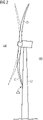
- Figure 1 shows a wind turbine 2 of the most common type in use at present.
- the wind turbine 2 has an aerodynamic rotor comprising three rotor blades 20 attached to a hub 21. Rotation of the aerodynamic rotor causes rotation of a generator rotor, so that output power can be exported by the wind turbine 2.
- the rotor blades 20 are shaped to optimize the amount of energy that can be extracted from the wind.
- a rotor blade 20 has an airfoil portion over much of its length, and the shape of the rotor blade transitions from a generally circular shape at the root end 20R to the flatter airfoil portion 20A, ultimately tapering to a thin tip 20T.
- the length of a rotor blade can be in the order of 80 m or more.
- This type of rotor blade may undergo significant deflection in the downwind direction, as illustrated in Figure 2 , which shows how the rotor blades 20 of such a wind turbine may be deflected by high wind loading in the downwind direction DW, i.e. in the direction of the tower 22.
- the downwind side DW and upwind side UW of the aerodynamic rotor are indicated.
- the axis of rotation is tilted upwards by several degrees and the rotor blades are pre-bent as indicated by the ghost outlines that show their "resting" shape in low wind conditions.
- Figure 3 shows a schematic of a rotor blade according to the invention.
- the diagram is a view of the rotor blade looking at the trailing edge TE. It shall be noted that the axes are not to the same scale.
- the diameter at the root end 20R is in the order of 3 - 4 m (X-axis), and the rotor blade length is in the order of 80 - 90 m (Y-axis).
- the pressure side 20P and suction side 20S of the rotor blade 20 are shown as indicated. It shall be assumed that the wind turbine is controlled so that its aerodynamic rotor always faces upwind UW during normal operation.
- the diagram shows a deflection shape (dotted line) to indicate the shape of an equivalent conventional rotor blade 20X under high wind conditions without corrective pitch control. Deflection can be measured from a reference, for example relative to a vertical line extending through 0 of the X-axis.
- the significant tip-to-tower deflection X of the conventional rotor blade 20X can have undesirable effects such as fatigue loading, tower collision, etc. For this reason, a conventional rotor blade is generally pitched out of the wind to decrease the tip-to-tower deflection X, resulting in a reduction in output power during normal operation.
- the tensioning device 10 can adjust the tension in the cable 11.
- the tensioning device 10 can adjust the tension in the cable 11.
- the resulting tensile force in the cable 11 causes the rotor blade 20 to deflect in the upwind direction UW, i.e. the pressure side undergoes compression.
- the tensioning device 10 can be an electric winch, for example.
- a tensioning device control signal 320 to the winch can control the winch motor in the desired manner.
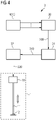
- the tensioning device control signal 320 can originate from a tensioning device control unit 32 as indicated in Figure 4 , which shows a block diagram of a wind turbine control arrangement 3.
- a monitoring arrangement 30 determines the downwind deflection 300 associated with the momentary wind loading on a rotor blade 20.
- the monitoring arrangement 30 may base its computations on relevant input variables such as wind speed, rotor blade angular position, rotor blade pitch angle etc., which can be supplied by the wind turbine controller WTC.
- An analysis unit 31 determines the magnitude of the corrective tensile force that must be exerted by the deformation arrangement 1 (indicated here only schematically) of that rotor blade in order to maintain the shape of the rotor blade, i.e. in order to prevent or counteract the predicted downward deflection.
- the analysis unit 31 may be provided with any relevant information such as the rotor azimuth angle, the rotor blade pitch angle, blade loading, a measurement of tip-to-tower clearance etc., which can be supplied by the wind turbine controller WTC.
- the monitoring arrangement 30 may determine that the current wind loading would result in a deflection of 3 m relative to a reference.
- the analysis unit 31 knowing the present state of the deformation arrangement 1, determines the magnitude of the tensile force that will be required to counteract the wind loading to avoid downwind deflection. For example, depending on the system design and the physical properties of the rotor blade, the magnitude of the tensile force can be in the order of 100 kN.
- the tensioning device control unit 32 translates the force magnitude 310 into an appropriate tensioning device control signal 320 that is then issued to the tensioning device of the deformation arrangement 1 of that rotor blade. In this way, the control arrangement 3 mitigates, prevents or counteracts the downwind deflection of that rotor blade.
- the exemplary control arrangement 3 described above comprises the monitoring arrangement 30, the analysis unit 31, and the tensioning device control unit 32.
- One or more components of the control arrangement can be realised locally in a wind turbine or at a remote location.
- the corrective force magnitude 310 can fluctuate accordingly.
- Figure 5 shows curves for wind load 51, predicted downwind deflection 52, corrective tensile force magnitude 53 and actual downwind deflection 54 respectively for a rotor blade according to the invention.
- the diagram shows that corrective tensile force (exerted in the cables of the deformation arrangement) prevents significant downwind deflection.
- This pre-emptive or corrective deformation of the rotor blades means that the wind turbine controller does not need to adjust the pitch angle to avoid rotor blade damage, but can continue to operate at the favourable high power output.
- the pitch angle and power output can remain essentially constant.
- the predicted downwind deflection 52 may correspond to the output of the monitoring arrangement 30, and the corrective tensile force magnitude 53 may correspond to the output 310 of the analysis unit 31 as explained in Figure 4 above.
- FIG. 6 shows curves for wind load 61, downwind deflection 62, pitch angle correction 63 and power output 64 respectively.
- the diagram illustrates how downwind deflection can only be avoided by adjusting the rotor blade pitch angle, which in turn results in a decrease in output power.
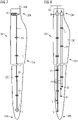
- FIG. 7 shows a schematic diagram of a possible embodiment of the inventive rotor blade 20, indicating the deformation arrangement 1 in the interior of the rotor blade.
- the diagram shows an electric winch 10 as tensioning device in the root end of the rotor blade.
- An anchor 12 is securely attached in an outboard end of the rotor blade, close to the tip 20T.
- the anchor 12 may have been partially embedded in the body of the rotor blade during a moulding process, for instance.
- a cable 11 extends from the winch 10 to the anchor 12 and passes through a number of cable guides 13 which ensure that the cable 11 remains at a constant distance from the pressure side interior surface 200.
- the cable 11 can be realised as a Bowden cable, i.e. as a wire rope protected by a flexible housing.
- the cable guides 13 are mounted on the interior face of the pressure side, for example by partial embedding during the moulding procedure.
- the outboard end 11out of the cable 11 is attached to the anchor 12.
- the inboard end 11in of the cable 11 is connected to the winch 10 and can be displaced by pulling in or letting out, depending on the tensioning device control signal 320 received from a tensioning device control unit as described above.
- FIG 8 shows a schematic diagram of another possible embodiment of the inventive rotor blade 20.
- two tensioning devices 10 are installed in the root end 20R of the rotor blade 20, and four anchors 12 are provided at intervals in the outboard end of the rotor blade.
- Two cables 11 extend from each tensioning device 10 and terminate separately at anchors 12 (passing through cable guides 13 as described above).
- the tensioning devices 10 receive the same tensioning device control signal 320, and operate to displace each cable 11 by the same amount.
- the tensioning cable could be incorporated into the lightning protection system (LPS) of a rotor blade, for example to act as a down conductor.
- the cable could be electrically connected to a receptor at the rotor blade exterior.
- an anchor of the deformation arrangement could be realised to also function as a lightning receptor.
- the principle of the invention could also be applied to other realisations, for example using an arrangement with a toothed belt or chain engaging with a motor-driven sprocket, instead of a cable and motor-driven winch.
Landscapes
- Engineering & Computer Science (AREA)
- Life Sciences & Earth Sciences (AREA)
- Sustainable Development (AREA)
- Sustainable Energy (AREA)
- Chemical & Material Sciences (AREA)
- Combustion & Propulsion (AREA)
- Mechanical Engineering (AREA)
- General Engineering & Computer Science (AREA)
- Physics & Mathematics (AREA)
- Fluid Mechanics (AREA)
- Wind Motors (AREA)
Priority Applications (4)
| Application Number | Priority Date | Filing Date | Title |
|---|---|---|---|
| EP20209749.9A EP4006334A1 (fr) | 2020-11-25 | 2020-11-25 | Pale de rotor d'éolienne |
| US18/253,851 US20240003331A1 (en) | 2020-11-25 | 2021-11-12 | Wind turbine rotor blade |
| EP21810613.6A EP4214413A1 (fr) | 2020-11-25 | 2021-11-12 | Pale de rotor d'éolienne |
| PCT/EP2021/081489 WO2022112020A1 (fr) | 2020-11-25 | 2021-11-12 | Pale de rotor d'éolienne |
Applications Claiming Priority (1)
| Application Number | Priority Date | Filing Date | Title |
|---|---|---|---|
| EP20209749.9A EP4006334A1 (fr) | 2020-11-25 | 2020-11-25 | Pale de rotor d'éolienne |
Publications (1)
| Publication Number | Publication Date |
|---|---|
| EP4006334A1 true EP4006334A1 (fr) | 2022-06-01 |
Family
ID=73597906
Family Applications (2)
| Application Number | Title | Priority Date | Filing Date |
|---|---|---|---|
| EP20209749.9A Withdrawn EP4006334A1 (fr) | 2020-11-25 | 2020-11-25 | Pale de rotor d'éolienne |
| EP21810613.6A Withdrawn EP4214413A1 (fr) | 2020-11-25 | 2021-11-12 | Pale de rotor d'éolienne |
Family Applications After (1)
| Application Number | Title | Priority Date | Filing Date |
|---|---|---|---|
| EP21810613.6A Withdrawn EP4214413A1 (fr) | 2020-11-25 | 2021-11-12 | Pale de rotor d'éolienne |
Country Status (3)
| Country | Link |
|---|---|
| US (1) | US20240003331A1 (fr) |
| EP (2) | EP4006334A1 (fr) |
| WO (1) | WO2022112020A1 (fr) |
Cited By (2)
| Publication number | Priority date | Publication date | Assignee | Title |
|---|---|---|---|---|
| CN119353143A (zh) * | 2023-09-28 | 2025-01-24 | 北京金风科创风电设备有限公司 | 弯曲变形矫正系统、叶片、风力发电机组及控制方法 |
| US12584457B2 (en) | 2022-05-12 | 2026-03-24 | Vestas Wind Systems A/S | Wind turbine |
Families Citing this family (1)
| Publication number | Priority date | Publication date | Assignee | Title |
|---|---|---|---|---|
| EP4006336A1 (fr) * | 2020-11-25 | 2022-06-01 | Siemens Gamesa Renewable Energy A/S | Pale de rotor d'éolienne |
Citations (4)
| Publication number | Priority date | Publication date | Assignee | Title |
|---|---|---|---|---|
| WO2007082821A1 (fr) * | 2006-01-19 | 2007-07-26 | Siemens Aktiengesellschaft | Pale de rotor utilisee dans une eolienne |
| US20100143135A1 (en) * | 2009-06-16 | 2010-06-10 | General Electric Company | Torsionally loadable wind turbine blade |
| EP2396539A2 (fr) * | 2009-02-11 | 2011-12-21 | Vestas Wind Systems A/S | Amélioration de la rigidité d'aubes d'éolienne |
| GB2485595A (en) * | 2010-11-19 | 2012-05-23 | Vestas Wind Sys As | Wind turbine |
Family Cites Families (6)
| Publication number | Priority date | Publication date | Assignee | Title |
|---|---|---|---|---|
| US7118338B2 (en) * | 2004-06-30 | 2006-10-10 | General Electric Company | Methods and apparatus for twist bend coupled (TCB) wind turbine blades |
| DE102010032120A1 (de) * | 2010-07-24 | 2012-01-26 | Robert Bosch Gmbh | Verfahren und Vorrichtung zur Bestimmung eines Biegewinkels eines Rotorblattes einer Windkraftanlage |
| US8463085B2 (en) * | 2010-12-17 | 2013-06-11 | General Electric Company | Systems and methods for monitoring a condition of a rotor blade for a wind turbine |
| EP2736805B1 (fr) * | 2011-07-22 | 2017-06-14 | LM WP Patent Holding A/S | Pale de turbine éolienne comprenant des générateurs de tourbillons |
| US20120141278A1 (en) * | 2011-09-06 | 2012-06-07 | General Electric Company | Rotor blade assembly and method for modifying load characteristic of rotor blade in wind turbine |
| US20140356181A1 (en) * | 2013-05-30 | 2014-12-04 | Luis A. Mailly | Wind turbine blade having a tensile-only stiffener for passive control of flap movement |
-
2020
- 2020-11-25 EP EP20209749.9A patent/EP4006334A1/fr not_active Withdrawn
-
2021
- 2021-11-12 US US18/253,851 patent/US20240003331A1/en not_active Abandoned
- 2021-11-12 WO PCT/EP2021/081489 patent/WO2022112020A1/fr not_active Ceased
- 2021-11-12 EP EP21810613.6A patent/EP4214413A1/fr not_active Withdrawn
Patent Citations (4)
| Publication number | Priority date | Publication date | Assignee | Title |
|---|---|---|---|---|
| WO2007082821A1 (fr) * | 2006-01-19 | 2007-07-26 | Siemens Aktiengesellschaft | Pale de rotor utilisee dans une eolienne |
| EP2396539A2 (fr) * | 2009-02-11 | 2011-12-21 | Vestas Wind Systems A/S | Amélioration de la rigidité d'aubes d'éolienne |
| US20100143135A1 (en) * | 2009-06-16 | 2010-06-10 | General Electric Company | Torsionally loadable wind turbine blade |
| GB2485595A (en) * | 2010-11-19 | 2012-05-23 | Vestas Wind Sys As | Wind turbine |
Cited By (2)
| Publication number | Priority date | Publication date | Assignee | Title |
|---|---|---|---|---|
| US12584457B2 (en) | 2022-05-12 | 2026-03-24 | Vestas Wind Systems A/S | Wind turbine |
| CN119353143A (zh) * | 2023-09-28 | 2025-01-24 | 北京金风科创风电设备有限公司 | 弯曲变形矫正系统、叶片、风力发电机组及控制方法 |
Also Published As
| Publication number | Publication date |
|---|---|
| EP4214413A1 (fr) | 2023-07-26 |
| US20240003331A1 (en) | 2024-01-04 |
| WO2022112020A1 (fr) | 2022-06-02 |
Similar Documents
| Publication | Publication Date | Title |
|---|---|---|
| US20240003331A1 (en) | Wind turbine rotor blade | |
| CN105408625B (zh) | 基于叶片上测量的负荷和加速度的风力涡轮机的操作方法及装置 | |
| US6465902B1 (en) | Controllable camber windmill blades | |
| EP2096300B1 (fr) | Procédé de controle du rapport de vitesse en bout de pales d'éoliennes | |
| EP2389510B1 (fr) | Commande d'un rotor d'eolienne au cours d'un processus d'arret par tangage et dispositif de modification de surface | |
| GB2485595A (en) | Wind turbine | |
| EP3324043A1 (fr) | Procédé de commande d'une éolienne flottante, système de commande d'éolienne et éolienne flottante | |
| US20140030090A1 (en) | Systems and methods for controlling tower clearance in a wind turbine | |
| CA3074397C (fr) | Eolienne et methode d'exploitation avec une variable de chargement | |
| EP4426933B1 (fr) | Procédé de réduction de charges de volet de pale dans une éolienne | |
| CN110520620A (zh) | 用于在风力涡轮机叶片变桨距轴承上减小负载的方法 | |
| CA2562600A1 (fr) | Methode d'exploitation d'une centrale eolienne | |
| WO2017218936A1 (fr) | Pale de rotor d'éolienne | |
| KR101941676B1 (ko) | 풍력발전기의 피치 제어 시스템 및 이를 포함하는 풍력발전시스템 | |
| CN110088460B (zh) | 用于控制风能设施的方法 | |
| KR20190124599A (ko) | 풍력발전기의 개별 피치 제어 시스템 및 이를 포함하는 풍력발전시스템 | |
| EP4006336A1 (fr) | Pale de rotor d'éolienne | |
| EP4172497B1 (fr) | Opération de turbine éolienne dans des conditions de vent extrêmes | |
| US12590571B2 (en) | Bearing for a wind turbine, method for monitoring an anomaly in a bearing of a wind turbine, system for monitoring an anomaly in a bearing of a wind turbine and wind turbine | |
| US20240133360A1 (en) | Protection of wind turbine components during yawing | |
| WO2025056132A1 (fr) | Système de protection contre la foudre | |
| CN120231687A (zh) | 叶片及风力发电机组 |
Legal Events
| Date | Code | Title | Description |
|---|---|---|---|
| PUAI | Public reference made under article 153(3) epc to a published international application that has entered the european phase |
Free format text: ORIGINAL CODE: 0009012 |
|
| STAA | Information on the status of an ep patent application or granted ep patent |
Free format text: STATUS: THE APPLICATION HAS BEEN PUBLISHED |
|
| AK | Designated contracting states |
Kind code of ref document: A1 Designated state(s): AL AT BE BG CH CY CZ DE DK EE ES FI FR GB GR HR HU IE IS IT LI LT LU LV MC MK MT NL NO PL PT RO RS SE SI SK SM TR |
|
| STAA | Information on the status of an ep patent application or granted ep patent |
Free format text: STATUS: THE APPLICATION IS DEEMED TO BE WITHDRAWN |
|
| 18D | Application deemed to be withdrawn |
Effective date: 20221202 |