EP4006340A1 - Vorrichtung und verfahren zum pumpen von produkten mit geringer verdampfung unter vakuum - Google Patents
Vorrichtung und verfahren zum pumpen von produkten mit geringer verdampfung unter vakuum Download PDFInfo
- Publication number
- EP4006340A1 EP4006340A1 EP21210448.3A EP21210448A EP4006340A1 EP 4006340 A1 EP4006340 A1 EP 4006340A1 EP 21210448 A EP21210448 A EP 21210448A EP 4006340 A1 EP4006340 A1 EP 4006340A1
- Authority
- EP
- European Patent Office
- Prior art keywords
- products
- transit
- pumping
- tanks
- storage enclosure
- Prior art date
- Legal status (The legal status is an assumption and is not a legal conclusion. Google has not performed a legal analysis and makes no representation as to the accuracy of the status listed.)
- Granted
Links
Images


Classifications
-
- F—MECHANICAL ENGINEERING; LIGHTING; HEATING; WEAPONS; BLASTING
- F04—POSITIVE - DISPLACEMENT MACHINES FOR LIQUIDS; PUMPS FOR LIQUIDS OR ELASTIC FLUIDS
- F04F—PUMPING OF FLUID BY DIRECT CONTACT OF ANOTHER FLUID OR BY USING INERTIA OF FLUID TO BE PUMPED; SIPHONS
- F04F3/00—Pumps using negative pressure acting directly on the liquid to be pumped
-
- B—PERFORMING OPERATIONS; TRANSPORTING
- B67—OPENING, CLOSING OR CLEANING BOTTLES, JARS OR SIMILAR CONTAINERS; LIQUID HANDLING
- B67D—DISPENSING, DELIVERING OR TRANSFERRING LIQUIDS, NOT OTHERWISE PROVIDED FOR
- B67D7/00—Apparatus or devices for transferring liquids from bulk storage containers or reservoirs into vehicles or into portable containers, e.g. for retail sale purposes
- B67D7/06—Details or accessories
- B67D7/76—Arrangements of devices for purifying liquids to be transferred, e.g. of filters, of air or water separators
-
- B—PERFORMING OPERATIONS; TRANSPORTING
- B01—PHYSICAL OR CHEMICAL PROCESSES OR APPARATUS IN GENERAL
- B01D—SEPARATION
- B01D19/00—Degasification of liquids
- B01D19/0042—Degasification of liquids modifying the liquid flow
- B01D19/0052—Degasification of liquids modifying the liquid flow in rotating vessels, vessels containing movable parts or in which centrifugal movement is caused
- B01D19/0057—Degasification of liquids modifying the liquid flow in rotating vessels, vessels containing movable parts or in which centrifugal movement is caused the centrifugal movement being caused by a vortex, e.g. using a cyclone, or by a tangential inlet
-
- B—PERFORMING OPERATIONS; TRANSPORTING
- B67—OPENING, CLOSING OR CLEANING BOTTLES, JARS OR SIMILAR CONTAINERS; LIQUID HANDLING
- B67D—DISPENSING, DELIVERING OR TRANSFERRING LIQUIDS, NOT OTHERWISE PROVIDED FOR
- B67D7/00—Apparatus or devices for transferring liquids from bulk storage containers or reservoirs into vehicles or into portable containers, e.g. for retail sale purposes
- B67D7/02—Apparatus or devices for transferring liquids from bulk storage containers or reservoirs into vehicles or into portable containers, e.g. for retail sale purposes for transferring liquids other than fuel or lubricants
- B67D7/0277—Apparatus or devices for transferring liquids from bulk storage containers or reservoirs into vehicles or into portable containers, e.g. for retail sale purposes for transferring liquids other than fuel or lubricants using negative pressure
-
- B—PERFORMING OPERATIONS; TRANSPORTING
- B67—OPENING, CLOSING OR CLEANING BOTTLES, JARS OR SIMILAR CONTAINERS; LIQUID HANDLING
- B67D—DISPENSING, DELIVERING OR TRANSFERRING LIQUIDS, NOT OTHERWISE PROVIDED FOR
- B67D7/00—Apparatus or devices for transferring liquids from bulk storage containers or reservoirs into vehicles or into portable containers, e.g. for retail sale purposes
- B67D7/06—Details or accessories
- B67D7/58—Arrangements of pumps
- B67D7/62—Arrangements of pumps power operated
-
- B—PERFORMING OPERATIONS; TRANSPORTING
- B67—OPENING, CLOSING OR CLEANING BOTTLES, JARS OR SIMILAR CONTAINERS; LIQUID HANDLING
- B67D—DISPENSING, DELIVERING OR TRANSFERRING LIQUIDS, NOT OTHERWISE PROVIDED FOR
- B67D7/00—Apparatus or devices for transferring liquids from bulk storage containers or reservoirs into vehicles or into portable containers, e.g. for retail sale purposes
- B67D7/06—Details or accessories
- B67D7/78—Arrangements of storage tanks, reservoirs or pipe-lines
-
- F—MECHANICAL ENGINEERING; LIGHTING; HEATING; WEAPONS; BLASTING
- F04—POSITIVE - DISPLACEMENT MACHINES FOR LIQUIDS; PUMPS FOR LIQUIDS OR ELASTIC FLUIDS
- F04B—POSITIVE-DISPLACEMENT MACHINES FOR LIQUIDS; PUMPS
- F04B15/00—Pumps adapted to handle specific fluids, e.g. by selection of specific materials for pumps or pump parts
- F04B15/02—Pumps adapted to handle specific fluids, e.g. by selection of specific materials for pumps or pump parts the fluids being viscous or non-homogeneous
-
- F—MECHANICAL ENGINEERING; LIGHTING; HEATING; WEAPONS; BLASTING
- F04—POSITIVE - DISPLACEMENT MACHINES FOR LIQUIDS; PUMPS FOR LIQUIDS OR ELASTIC FLUIDS
- F04B—POSITIVE-DISPLACEMENT MACHINES FOR LIQUIDS; PUMPS
- F04B23/00—Pumping installations or systems
- F04B23/02—Pumping installations or systems having reservoirs
-
- F—MECHANICAL ENGINEERING; LIGHTING; HEATING; WEAPONS; BLASTING
- F04—POSITIVE - DISPLACEMENT MACHINES FOR LIQUIDS; PUMPS FOR LIQUIDS OR ELASTIC FLUIDS
- F04B—POSITIVE-DISPLACEMENT MACHINES FOR LIQUIDS; PUMPS
- F04B23/00—Pumping installations or systems
- F04B23/04—Combinations of two or more pumps
- F04B23/08—Combinations of two or more pumps the pumps being of different types
-
- F—MECHANICAL ENGINEERING; LIGHTING; HEATING; WEAPONS; BLASTING
- F04—POSITIVE - DISPLACEMENT MACHINES FOR LIQUIDS; PUMPS FOR LIQUIDS OR ELASTIC FLUIDS
- F04F—PUMPING OF FLUID BY DIRECT CONTACT OF ANOTHER FLUID OR BY USING INERTIA OF FLUID TO BE PUMPED; SIPHONS
- F04F5/00—Jet pumps, i.e. devices in which flow is induced by pressure drop caused by velocity of another fluid flow
- F04F5/02—Jet pumps, i.e. devices in which flow is induced by pressure drop caused by velocity of another fluid flow the inducing fluid being liquid
- F04F5/04—Jet pumps, i.e. devices in which flow is induced by pressure drop caused by velocity of another fluid flow the inducing fluid being liquid displacing elastic fluids
-
- F—MECHANICAL ENGINEERING; LIGHTING; HEATING; WEAPONS; BLASTING
- F04—POSITIVE - DISPLACEMENT MACHINES FOR LIQUIDS; PUMPS FOR LIQUIDS OR ELASTIC FLUIDS
- F04F—PUMPING OF FLUID BY DIRECT CONTACT OF ANOTHER FLUID OR BY USING INERTIA OF FLUID TO BE PUMPED; SIPHONS
- F04F5/00—Jet pumps, i.e. devices in which flow is induced by pressure drop caused by velocity of another fluid flow
- F04F5/44—Component parts, details, or accessories not provided for in, or of interest apart from, groups F04F5/02 - F04F5/42
- F04F5/48—Control
- F04F5/52—Control of evacuating pumps
-
- F—MECHANICAL ENGINEERING; LIGHTING; HEATING; WEAPONS; BLASTING
- F04—POSITIVE - DISPLACEMENT MACHINES FOR LIQUIDS; PUMPS FOR LIQUIDS OR ELASTIC FLUIDS
- F04F—PUMPING OF FLUID BY DIRECT CONTACT OF ANOTHER FLUID OR BY USING INERTIA OF FLUID TO BE PUMPED; SIPHONS
- F04F5/00—Jet pumps, i.e. devices in which flow is induced by pressure drop caused by velocity of another fluid flow
- F04F5/54—Installations characterised by use of jet pumps, e.g. combinations of two or more jet pumps of different type
Definitions
- the present invention relates to a device and a method for pumping low evaporation products under vacuum, from a pumping zone to a storage enclosure.
- the invention relates to a device and a method for pumping products such as hydrocarbons, acids, bases, sewage sludge, biological sludge, primary sludge, and in general any product likely to generate an explosive atmosphere and/or emit volatile organic compounds into the atmosphere during pumping.
- products such as hydrocarbons, acids, bases, sewage sludge, biological sludge, primary sludge, and in general any product likely to generate an explosive atmosphere and/or emit volatile organic compounds into the atmosphere during pumping.
- Such pumping operations are also necessary in particular for purging industrial sewers, recovering waste produced by high-pressure water cleaning of industrial installations, extracting sludge from treatment plants, for drying tank bottoms so as to allow their inspection or maintenance, etc.
- the industrial cleaning activity also requires the pumping means to be completely purged and degassed due to the diversity of the products treated, the combination of which could generate a dangerous chemical reaction.
- This technique has the advantage of allowing the operation of the vacuum pump to be stopped during the pumping operation by maintaining a suction capacity as long as the differential with respect to atmospheric pressure exists. This technique therefore makes it possible to completely empty the tank to be emptied. In addition, it allows the pump to be installed at great distances from the product, to avoid contact between the product and the pump, except for vapors and gases, and to limit the quantity of pollutants released.
- This pumping device comprises a vacuum source, a product suction nozzle, a pressure source, two transit tanks for product, and a set of controlled valves, connecting simultaneously and alternately, one of the transit tanks to the vacuum source and to the suction nozzle and the other of the transit tanks to the pressure source and to a product reception tank.
- the vacuum suction and the pressurization of the transit tanks are preferably carried out by a single and same vacuum pump.
- the vacuum source and the pressure source being respectively constituted by the suction orifice and by the discharge orifice of the vacuum pump.
- the two transit tanks work alternately, which makes it possible to limit the time vacuum exposure of the pumped products, so as to limit the physical phenomenon of desorption of the gases from the products.
- the document solution FR1 559 570 is not completely satisfactory.
- the use of a single vacuum pump for suction and delivery can limit the suction capacity and increase the time required for liquids to be placed under vacuum in the transit tanks, with the consequence of a possible increase in the release of volatile products. .
- the product pumping time during which the gas desorption phenomena take place, is minimized due to the small volume of the products pumped under vacuum. Indeed, there is no accumulation of time that the pumped products pass under vacuum.
- the suction of the products to be pumped can be interrupted.
- the suction unit enables the pumping to be resumed quickly and, simultaneously, the transfer unit enables the degassed products to be pushed back into the storage enclosure.
- the transfer of non-gaseous products is obtained by a volumetric pump which limits the exposure time of the products to vacuum and therefore the desorption of gases in the storage enclosure and allows filling from the bottom of the enclosure. storage without bi-phase separator.
- the diameter of each of said transit tanks is between 70 centimeters and 80 centimeters.
- the ratio between the volume and the upper surface of the transit tanks in contact with the products is between 1/30 and 1/25.
- the suction unit is provided with a high pressure pump supplying said at least two hydro-ejectors with high-pressure water, each of said at least two hydro-ejectors discharging water into at least a water tank which feeds said high pressure pump.
- the suction unit works on a water recycling principle.
- one of said at least two hydro-ejectors is configured to compensate for suction variations over time.
- the discharge network also comprises a first discharge conduit for the gases produced by desorption in the storage enclosure, connecting the storage enclosure to said at least one water tank.
- the suction unit is configured to generate a vacuum in the storage enclosure, to assist in the direct pumping of products comprising solid elements via a rear pipe.
- the discharge network also comprises a second conduit for the rejection of gases produced by desorption in the storage enclosure connecting said storage enclosure to said at least two hydro-ejectors, said second conduit also contributing to the under vacuum of the storage enclosure.
- the pumping device comprises a cyclo-filter configured to filter the gases from each of said transit tanks, said cyclo-filter being arranged between said at least two hydro-ejectors and each of said tanks of transit.
- the cyclo-filter is also configured to filter the gases from the storage enclosure, said cyclo-filter being arranged between said at least two hydro-ejectors and said storage enclosure.
- the transfer unit is also configured to transfer said non-gaseous products from the storage enclosure to another storage area.
- the transfer unit thus serves both for filling and emptying the storage enclosure.
- the transfer unit can also pump liquid or pasty products from a tank and push the non-gaseous products to another storage area.
- the filling level of each of said transit tanks is detected by radar sensors.
- the present invention also relates to a method for pumping products from a pumping zone to a storage enclosure.
- the pumping time of the products is minimized.
- the suction of the products to be pumped can be interrupted.
- the suction unit enables the pumping to be resumed quickly and, simultaneously, the transfer unit enables the degassed products to be pushed back into the storage enclosure.
- the transfer of non-gaseous products is carried out by a volumetric pump (part of a transfer unit which is separate from the suction unit).
- the maximum vacuum duration of the products pumped into the transit tanks is less than or equal to 12 seconds.
- said pumping method also comprises a gas rejection step, implemented simultaneously with the implementation of the first and second valve control steps, this gas rejection step consisting in rejecting the gases produced during the separation of the products in each of said transit tanks towards a rejection zone via a rejection network.
- said pumping method comprises a vacuum step consisting in generating, with the aid of the suction unit, a direct vacuum in the storage enclosure, to promote the pumping of products comprising solid elements into the storage enclosure.
- said pumping method further comprises a step of transferring non-gaseous products from the storage enclosure to another storage zone by the transfer unit.
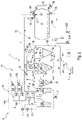
- the product pumping device (hereinafter “pump device 1”) making it possible to illustrate the invention and represented schematically on the figure 1 and 2 , is a device intended to pump products such as sludge, solvents, oil slicks, etc., from a pumping zone 2 to a storage enclosure 3.
- the pumping device 1 comprises two transit tanks 4A and 4B. These transit tanks 4A and 4B are preferably cyclonic or hydrocyclone tanks. Each of these transit tanks 4A and 4B is intended to contain products to be pumped. The transit tanks 4A and 4B are configured to make it possible to reduce the vacuum exposure time of the pumped product in order to minimize the risk of physical transformation of the pumped products into gas.
- Each of the transit tanks 4A and 4B is provided with a product inlet 5A, 5B to receive the products, a drain outlet 7A, 7B to discharge the non-gaseous products resulting from the separation into different phases of the products pumped towards a storage enclosure 3 and a suction port 6A, 6B for vacuuming or venting.
- each of the transit tanks 4A, 4B has a diameter of between 70 centimeters and 80 centimeters. Furthermore, each of the transit tanks 4A, 4B has a reduced capacity, preferably between 100 to 150 liters.
- the ratio between the volume and the surface of the transit tanks 4A and 4B in contact with the pumped products is preferably comprised in a ratio between 1/30 and 1/25. The desorption phenomena in the transit tanks 4A and 4B are related to their dimensions and to the vacuum surface of the products pumped in the transit tanks 4A and 4B.
- the vacuum exposure time of the pumped products is reduced, for example for 4 cubic meters, by 240 seconds in the case of direct pumping by the storage enclosure 3 to 12 seconds by the transit tanks 4A and 4B, which corresponds to a reduction in the vacuuming time of twenty times compared to conventional pumping means.
- the more the volume of the pumped products increases the greater the time of exposure to the vacuum of the products and therefore the production of gas by desorption.
- the vacuum exposure time of the pumped products does not depend on the volume of pumped products and remains constant.
- 4K radar sensors can be provided to detect the filling level of the tanks 4A and 4B. These 4K radar sensors are more efficient than mechanical means.
- each of the transit tanks 4A, 4B can be fitted with floating balls 4Z making it possible to block any leakage of products through the suction orifice 6A, 6B.
- the pumping device 1 further comprises a pumping system 8, which can generate a suction of the products from the pumping zone 2 towards the transit tanks 4A and 4B and generate a discharge of the non-gaseous pumped products following the phenomena of thermal desorption in transit tanks 4A and 4B towards storage enclosure 3.
- a pumping system 8 which can generate a suction of the products from the pumping zone 2 towards the transit tanks 4A and 4B and generate a discharge of the non-gaseous pumped products following the phenomena of thermal desorption in transit tanks 4A and 4B towards storage enclosure 3.
- this pumping system 8 is formed by a suction unit 13 and a transfer unit 20. As shown in the figure 1 and 2 , the suction unit 13 and the transfer unit 20 are two separate units.
- the suction unit 13 generates suction of the products from the pumping zone 2 by placing the transit tanks 4A and 4B under vacuum. It is connected to the suction ports 6A and 6B of the transit tanks 4A and 4B.
- the products sucked from the pumping zone 2 to each of the transit tanks 4A, 4B circulate through product transfer pipes 9A and 9B which connect the pumping zone 2 (via for example a common pipe) to the product inlets 5A and 5B transit tanks 4A and 4B.
- the suction unit 13 (also called the vacuum unit) comprises at least two hydro-ejectors 13A and 13B.
- the hydro-ejectors 13A and 13B are connected to a high-pressure pump 14, which supplies them with high-pressure water via a pipe 14A on which valves 13C and 13D are arranged.
- the high-pressure pump 14 makes it possible to ensure a flow of pressure water according to demand, in each of the hydro-ejectors 13A, 13B, when the valves 13C and 13D are open.
- the use of a high pressure pump makes it possible to modulate the flow rate of high pressure water which it injects into the hydro-ejectors 13A and 13B.
- a vacuum pump can see its rotation speed vary by a factor of 1.5. For example, its speed of rotation can vary between 1000 cubic meters per hour to 1500 cubic meters per hour or between 1500 cubic meters per hour and 3000 cubic meters per hour.
- the suction unit 13 has generated the vacuum in the transit tanks 4A and 4B in a few minutes, it is sufficient simply to compensate for the air intakes which may require, for example, 20% of the flow .
- the modulation of the water flow can also be generated by a booster pump 141 arranged upstream of the high pressure pump 14.
- the high pressure pump makes it possible to generate a pressure of between 500 bar and 2000 bar.
- the hydro-ejectors 13A and 13B deliver the water supplied by the high pressure pump 14 into a water tank 15A via the conduits 18A and 15D.
- This water tank 15A communicates with another water tank 15B so that the two water tanks 15A and 15B serve as water reservoirs for the high pressure pump 14.
- Each water tank 15A, 15B is provided with a valve 27 for emptying and frost protection.
- Each water tank 15A, 15B also includes a bursting pot 15F.
- the presence of two water tanks 15A and 15B, arranged on either side of the storage enclosure 2, results from the need to balance the pumping device 1.
- a water filter 26 is arranged between the water tanks 15A and 15B and the high pressure pump 14.
- Other filters including a self-cleaning filter and a filter with five micron pockets, can also be arranged between the booster pump 141 and the high pressure pump 14.
- Each of the hydro-injectors 13A, 13B is provided with a suction mouth 16A, 16B which is connected to the suction orifice 6A, 6B of each transit tank 4A, 4B notably via pipes 17A, 17B and 18 vacuum rejection.
- the passage of water in the hydro-ejectors 13A and 13B generates, by Venturi effect, a call for air at the level of the suction mouth 16A, 16B of each hydro-ejector 13A, 13B.
- This call for air generated in the pipes 17A, 17B and 18 produces the evacuation of the transit tanks 4A and 4B.
- water has a good performance, better for example than air.
- the water used makes it possible to trap the gases by wetting.
- the use of the Venturi effect with high pressure water (about 300 bar) makes it possible to obtain a vacuum of 90%.
- one of the hydro-ejectors 13A is used to generate the initial suction or initial vacuuming of the transit tanks 4A and B and the other hydro-ejector 13B is configured to compensate for the variations or intakes of air over time once the vacuum is generated.
- non-gaseous products may contain solid elements so that their pumping is done directly in the storage enclosure 3 by placing it under vacuum and by pumping through a pipe 3C located near the bottom of the tank. storage enclosure 2.
- the suction unit 13 generates suction in the storage enclosure 3 via a conduit 3G connecting the suction mouth 16A, 16B of each hydro-ejector 13A, 13B to an orifice arranged on the storage enclosure 3. This orifice is opened or closed by a valve 3D arranged on the conduit 3G.
- the transfer unit 20 generates the emptying of the non-gaseous products (resulting from the separation of the products in the transit tanks 4A and 4B) towards the storage enclosure 3.
- the non-gaseous products gases circulate in a transfer pipe 20A which connects the transfer outlets 7A and 7B to the storage enclosure 3.
- a valve 3A is arranged on the pipe 20A near a product inlet in the bottom of the storage enclosure. storage 3.
- the transfer unit 20 comprises a volumetric pump 20 which pumps the non-gaseous products and delivers them into the storage enclosure 3.
- This volumetric pump 20 is mounted on the transfer pipe 20A so that 'it is connected to the discharge outlet 7A, 7B of each of the transit tanks 4A, 4B and the inlet of non-gaseous products of the storage enclosure 3.
- the volumetric pump 20 is a pump volumetric type ROOTES for fluids and pastes.
- the direction of delivery of the volumetric pump 20 can be reversed.
- the volumetric pump 20 can then deliver the non-gaseous products from the storage enclosure 3 to another storage area (not shown).
- “Other storage area” means another storage enclosure, a specialized processing and/or storage site, etc.
- Valves 22A and 22B can be arranged on either side of the volumetric pump 20 so as to suck in or push back the non-gaseous products depending on the direction of travel.
- the volumetric pump 20 has a dual function of filling and emptying the storage enclosure 3 and also offers the possibility of being used as a simple transfer pump.
- the pumping device 1 also includes a gas discharge network 19, in which circulate the gases generated during the pumping of the products.
- This network 19 is configured to reject these gases towards a rejection zone. To do this, it comprises the pipes 17A and 17B which connect the suction port 6A, 6B of each transit tank 4A, 4B to the suction mouth 16A, 16B of each hydro-ejector 13A, 13B of the suction unit 13.
- the vacuuming of the transit tanks 4A, 4B participates in the rejection of the gases resulting from the separation of the pumped products into non-gaseous products and gaseous products due to the phenomena of desorption in these tanks 4A and 4B .
- the network 19 also includes the water transfer pipe 18A which connects the hydro-ejectors 13A and 13B to the water tank 15A.
- the gas vapors entering the hydro-injectors 13 through the suction mouths 13A and 13B are trapped by wetting in the water which is discharged into the water tanks 15A and 15B. This gas trapping provides environmental relief to potentially toxic and polluting gas releases.
- the gas discharge network 19 also comprises a pipe 15C which is mounted by one end on the upper part of the water tanks 15A and 15B and whose other end 15E opens onto the discharge zone so that the trapped gases in the water can escape to the disposal area.
- the network 19 also comprises a rejection conduit 3F which connects the storage enclosure storage 3 directly to the water tank 15A.
- the pipe 3G connecting the suction mouth 16A, 16B of each hydro-ejector 13A, 13B to the orifice near the valve 3D contributes to the discharge of the gases resulting from the desorption in the storage enclosure 3 and is part of the discharge network 19.
- the pumping device 1 also comprises a cyclo-filter 23 which is arranged between the hydro-ejectors 13A and 13B on one side and the transit tanks 4A and 4B and the storage enclosure 3 on the other side.
- the cyclo-filter 23 is also provided with a drain valve 27 also allowing frost protection.
- the pipes 17A and 17B and the pipe 3G have a common part on which the cyclo-filter 23 is mounted so that the gases circulating in these pipes are filtered by the cyclo-filter 23 before entering in the hydro-ejectors 13A and 13B.
- the filtering of the gases in the cyclo-filter 23 thus makes it possible, in particular, to eliminate gases of small particles which could pollute the suction unit 13.
- the pumping device 1 is also provided with a plurality of valves 3A, 3B, 3D, 3E, 3I, 4C, 4D, 4I and 4J whose opening, closing and orientation are controlled by a system control 25 of the usual type, not further described in this description.
- the opening, closing and orientation of this plurality of valves 3A, 3B, 3D, 3E, 3I, 4C, 4D, 4I and 4J can, alternately, either allow or block the pumping of the products from the zone of pumping 2 to one of the transit tanks 4A, 4B placed under vacuum by the suction unit 13 and the discharge of the non-gaseous products from the other transit tank 4B, 4A to the storage enclosure 3 by the discharge unit 20, as specified below.
- valves 4C, 4D, 4I and 4J are three-way valves.
- the valve 4J is arranged between a pumping pipe 2A and the pipes 9A and 9B which together connect the pumping zone 2 to the product inlets 5A and 5B of the transit tanks 4A and 4B.
- the valve 4J can take two orientations making it possible to direct the pumping of the products towards one or the other of the transit tanks 4A and 4B.
- Valve 4I is arranged on line 20A between transfer pump 20 and outlet ports 7A and 7B.
- the valve 4I is capable of allowing the transfer of non-gaseous products into the storage enclosure 3 and coming either from the transit tank 4A or from the transit tank 4B depending on its orientation.
- the valves 4C and 4D are each arranged on one of the pipes 17A, 17B which connects a suction port 6A, 6B to the suction unit 13.
- the control system 25 can simultaneously control the orientation of the three-way valves 4C, 4D, 4I and 4J.
- the transit tank 4B is connected to the suction unit 13 by the pipes 17B and 18 and to the pumping zone 2 by the pipes 9B and 2A.
- the transit tank 4A is connected, for its part, to the transfer unit 20 by the transfer pipe 20A which leads to the storage enclosure 3.
- the control system 25 can, alternately, simultaneously control the different orientations of the valves 4C and 4D and the orientation of the valve 4J for filling the transit tank 4B only and the orientation of the valve 4I for the emptying of the transit tank 4A.
- Each of the 4C, 4D, 4I and 4D valves includes two orientations.
- the first orientation of the valves 4C and 4D corresponds, respectively, to the opening of a venting of the transit tank 4A and to the opening of a communication of the transit tank 4B with the unit suction 13.
- the second orientation of the valves 4C and 4D corresponds, respectively, to the opening of a venting of the transit tank 4B and to the opening of a communication of the transit tank 4A with the suction unit 13.
- first, respectively second, orientation of the valve 4I allows the opening, respectively closing, of the communication between the transit tank 4A and the storage enclosure 3 and the closing, respectively opening, of the communication between the transit tank 4B and the storage enclosure 3.
- the first, respectively second, orientation of the valve 4J allows the opening, respectively closing, of the communication between the pumping zone 2 and the transit tank 4B, and the closure, respectively opening, of the communication between the transit tank 4A and the storage enclosure 3.
- the transit tank 4A is connected to the suction unit 13 by the pipes 17A and 18 and to the pumping zone 2 by the transfer pipes 2A and 9A while the transit tank 4B is connected to the pump of transfer 20 via the transfer line 20A which connects it to the storage enclosure 3.
- the pumping device implements a method of pumping products from the pumping zone 2 towards the enclosure of storage 3.
- This pumping process which generates low vacuum evaporation of products, comprises a plurality of steps specified below.
- the high pressure pump 14 supplies water at high pressure to the hydro-ejectors 13A and 13B. More particularly, the high pressure pump 14 makes it possible to create a vacuum by injecting high pressure water into one of the hydro-ejectors 13A, 13B at a rate of 70 liters at 1000 bar corresponding to a power of 140 kilowatts and approximately 2500 cubic meters per hour of suction volume. With such power, the vacuum is achieved quickly.
- the acceleration of the water in the hydro-ejector 13A, 13B generates, by Venturi effect, a depression at the level of the suction mouths 16A and 16B. This air depression is at the origin of the vacuuming of the transit tanks 4A and 4B via the conduits 17A, 17B and 18. It can also generate a vacuuming of the storage enclosure 3 by via conduit 3G if the products to be pumped include solid elements.
- valve 13C of the hydro-ejector 13A When the vacuum is created, the valve 13C of the hydro-ejector 13A is closed so as to cut off the flow of water entering this hydro-ejector 13A.
- the valve 13D previously closed, is then opened so that the high pressure pump 14 supplies high pressure water to the second hydro-ejector 13B.
- This 13B hydro-ejector uses, for example, 15 liters of water at a pressure of 1000bar only to compensate for air intakes. This reduction in flow makes it possible to pass to an absorbed power of approximately 30 kilowatts and 500 cubic meters per hour of suction flow. This phase allows significant energy savings to be made.
- the suction generated by the suction unit 13 leads to the pumping of the products from the pumping zone 2 towards the transit tank 4B via the conduits 2A and 9B as illustrated by the arrows on the figure 1 .
- the first orientation of the valve 4C which places the transit tank 4A in the open air prevents the aspiration of product from the pumping zone 2 into this transit tank 4A.
- the first orientation of the valve 4I puts the transfer outlet 7A of the transit tank 4A in communication with the volumetric pump 20 to deliver the non-gaseous products resulting from a prior separation of the pumped products, towards the storage enclosure 3 by through line 20A.
- the transit tank 4A then empties.
- the control system 25 controls the second orientation of the valve 4C and the second orientation of the valve 4J so that the transit tank 4A is placed under vacuum by the suction unit 13 and fills with products from the pumping zone 2.
- the system controls the second orientation of the valve 4D and the second orientation of the valve 4I so that the transit tank 4B is venting and the transfer unit 20 transfers the non-gaseous products previously pumped into this transit tank 4B to the storage enclosure 3.
- the suction generated by the suction unit 13 leads to the pumping products from the pumping zone 2 to the transit tank 4A via the pipes 2A and 9A as illustrated by the arrows on the figure 2 .
- the second orientation of the valve 4I puts the transfer outlet 7B of the transit tank 4B in communication with the volumetric pump 20 to deliver the non-gaseous products resulting from a prior separation of the pumped products, towards the storage enclosure 3 by through line 20A.
- the transit tank 4B then empties.
- the two transit tanks 4A and 4B work alternately, which makes it possible to limit the time of exposure to vacuum of the pumped products so as to limit the phenomena of desorption of the gases dissolved in the products.
- This exposure time is a maximum of 12 seconds.
- a gas rejection step is implemented during the steps described previously. During this gas discharge step, the gases generated by the separation of the products and by desorption phenomena are discharged into a discharge zone via the network 19 of discharge.
- the first orientation of the valve 4D allows the evacuation of the gases resulting from the pumping of products.
- gases or non-gaseous products pass through the cyclo-filter 23 then the hydro-ejectors 13A and 13B where they are trapped by wetting in the water tanks 15A, 15B before being evacuated by the vertical pipe 15C towards the zone of rejection.
- the second orientation of the valve 4C allows the evacuation of the gases resulting from the pumping of products. These gases pass through the cyclo-filter 23 then the hydro-ejectors 13A and 13B where they are trapped by wetting in the water tanks 15A, 15B before being evacuated by the vertical pipe 15C towards the discharge zone.
- the flow of non-gaseous products is illustrated by the arrow on the figure 2 .
- the gases produced by desorption in the storage enclosure 3 circulate in the pipes 3F and 15D as far as the tank 15A , 15B of water then are evacuated by the vertical pipe 15C.
- the non-gaseous products present in the storage enclosure 3 can be discharged from the storage enclosure. storage 3 to another area (not shown) by the transfer unit 20.
- the pumping device 1, as described can be used for various operations or works (at high pressure).
- the pumping device 1 and the storage enclosure 3 can be part of a unit 29 for pumping and storing products.
- the unit 29 (therefore comprising the pumping device 1 and the storage enclosure 3 is mounted on a sewer cleaner 30 represented on the picture 3 .
- the sewer cleaner 30 comprises a carrier vehicle 31 provided with a frame 32 intended to receive equipment.
- the frame 32 comprises in particular, from the rear to the front, the storage enclosure 3 the transit tanks of which only the transit tank 4A is visible on the picture 3 , and a casing 33 which comprises at least part of the elements of the suction unit 13 and of the discharge unit 20.
- the sewer cleaner 30 can be a sanitation sewer cleaner which is intended, in particular, to ensure cleaning and pumping operations for wastewater networks and sanitation works.
- the hydrocleaner 30 can also be an industrial hydrocleaner which is intended for cleaning work on equipment and industrial installations, and in particular for cleaning work on oil and oil-related sites.
Landscapes
- Engineering & Computer Science (AREA)
- Mechanical Engineering (AREA)
- General Engineering & Computer Science (AREA)
- Physics & Mathematics (AREA)
- Fluid Mechanics (AREA)
- Chemical & Material Sciences (AREA)
- Chemical Kinetics & Catalysis (AREA)
- Jet Pumps And Other Pumps (AREA)
Applications Claiming Priority (1)
| Application Number | Priority Date | Filing Date | Title |
|---|---|---|---|
| FR2012381A FR3116867B1 (fr) | 2020-11-30 | 2020-11-30 | Dispositif et procédé de pompage de produits à faible évaporation sous vide. |
Publications (3)
| Publication Number | Publication Date |
|---|---|
| EP4006340A1 true EP4006340A1 (de) | 2022-06-01 |
| EP4006340B1 EP4006340B1 (de) | 2024-07-17 |
| EP4006340C0 EP4006340C0 (de) | 2024-07-17 |
Family
ID=74183444
Family Applications (1)
| Application Number | Title | Priority Date | Filing Date |
|---|---|---|---|
| EP21210448.3A Active EP4006340B1 (de) | 2020-11-30 | 2021-11-25 | Vorrichtung und verfahren zum pumpen von produkten mit geringer verdampfung unter vakuum |
Country Status (4)
| Country | Link |
|---|---|
| US (1) | US11795050B2 (de) |
| EP (1) | EP4006340B1 (de) |
| CA (1) | CA3138466A1 (de) |
| FR (1) | FR3116867B1 (de) |
Cited By (1)
| Publication number | Priority date | Publication date | Assignee | Title |
|---|---|---|---|---|
| FR3137138A1 (fr) * | 2022-06-28 | 2023-12-29 | Ortec Expansion | Dispositif et procédé d’aspiration et de mise en pression à l’aide d’un hydro-éjecteur. |
Citations (4)
| Publication number | Priority date | Publication date | Assignee | Title |
|---|---|---|---|---|
| DE483213C (de) * | 1929-10-02 | Atlas Werke Akt Ges | Einrichtung zur Selbstentlueftung von Speisewasser u. dgl. unter Luftleere und ohne Erwaermung | |
| FR1559570A (de) | 1964-08-07 | 1969-03-14 | ||
| CN2761896Y (zh) * | 2005-01-12 | 2006-03-01 | 巩义市晨光真空设备厂 | 全低架蒸汽喷射真空系统 |
| JP4227692B2 (ja) * | 1998-12-17 | 2009-02-18 | 株式会社サムソン | 複数の循環水槽を持った水エジェクタ式真空発生装置 |
Family Cites Families (3)
| Publication number | Priority date | Publication date | Assignee | Title |
|---|---|---|---|---|
| FR2576315A1 (fr) * | 1984-01-26 | 1986-07-25 | Cezilly Francois | Dispositif d'economie d'energie et de suppression des pollutions sur les colonnes de desodorisation d'huiles et de corps gras |
| DE10017379C2 (de) * | 2000-04-07 | 2002-01-24 | Bartec Componenten & Syst Gmbh | Vorrichtung und Verfahren zur Förderung eines Mediums |
| CN210484218U (zh) * | 2019-09-17 | 2020-05-08 | 上海紫东尼龙材料科技有限公司 | 回收造粒蒸汽喷射抽真空结构 |
-
2020
- 2020-11-30 FR FR2012381A patent/FR3116867B1/fr active Active
-
2021
- 2021-11-10 CA CA3138466A patent/CA3138466A1/fr active Pending
- 2021-11-25 EP EP21210448.3A patent/EP4006340B1/de active Active
- 2021-11-29 US US17/536,375 patent/US11795050B2/en active Active
Patent Citations (4)
| Publication number | Priority date | Publication date | Assignee | Title |
|---|---|---|---|---|
| DE483213C (de) * | 1929-10-02 | Atlas Werke Akt Ges | Einrichtung zur Selbstentlueftung von Speisewasser u. dgl. unter Luftleere und ohne Erwaermung | |
| FR1559570A (de) | 1964-08-07 | 1969-03-14 | ||
| JP4227692B2 (ja) * | 1998-12-17 | 2009-02-18 | 株式会社サムソン | 複数の循環水槽を持った水エジェクタ式真空発生装置 |
| CN2761896Y (zh) * | 2005-01-12 | 2006-03-01 | 巩义市晨光真空设备厂 | 全低架蒸汽喷射真空系统 |
Cited By (2)
| Publication number | Priority date | Publication date | Assignee | Title |
|---|---|---|---|---|
| FR3137138A1 (fr) * | 2022-06-28 | 2023-12-29 | Ortec Expansion | Dispositif et procédé d’aspiration et de mise en pression à l’aide d’un hydro-éjecteur. |
| EP4299903A1 (de) * | 2022-06-28 | 2024-01-03 | Ortec Expansion | Vorrichtung und verfahren zum ansaugen und drucksetzen mit einem hydroejektor. |
Also Published As
| Publication number | Publication date |
|---|---|
| CA3138466A1 (fr) | 2022-05-30 |
| US20220169496A1 (en) | 2022-06-02 |
| FR3116867B1 (fr) | 2023-04-14 |
| EP4006340B1 (de) | 2024-07-17 |
| US11795050B2 (en) | 2023-10-24 |
| EP4006340C0 (de) | 2024-07-17 |
| FR3116867A1 (fr) | 2022-06-03 |
Similar Documents
| Publication | Publication Date | Title |
|---|---|---|
| EP3033525B1 (de) | Pumpverfahren und -einheit für brennbare produkte, welche eine explosive mischung erzeugen können | |
| EP2307624B1 (de) | Automatisches und sich schnell öffnendes system für volltankablass | |
| EP4006340B1 (de) | Vorrichtung und verfahren zum pumpen von produkten mit geringer verdampfung unter vakuum | |
| EP3359815B1 (de) | Verfahren und vorrichtung zum pumpen eines produkts durch absaugen | |
| FR2990936A1 (fr) | Installation de lavage et de recyclage d'eau chargee de gravats | |
| EP3894060B1 (de) | Vorrichtung zum einspritzen von flüssigkeit in eine flüssigkeit, verfahren zur reinigung dieser vorrichtung und abwasserbehandlungsanlage | |
| FR3007755B1 (fr) | Station de recyclage des eaux de lavage de materiels de chantier | |
| EP0956165B1 (de) | Verfahren und vielzweckvorrichtung zur erhaltung metastabiler flüssigkeiten | |
| EP1732670A1 (de) | Vorrichtung zur behandlung von gasförmigen ausströmungen | |
| FR3030318B1 (fr) | Dispositif de pretraitement de sediments preleves sur un fond d'un milieu liquide comprenant des etages de tamisage successifs | |
| EP1518614B1 (de) | Vorrichtung und Verfahren zur Grundwassersanierung | |
| EP3409340B1 (de) | Anlage und verfahren zum filtern eines flüssig-/feststoff-gemisches | |
| EP4299903B1 (de) | Vorrichtung und verfahren zum ansaugen und drucksetzen mit einem hydroejektor | |
| BE1014429A3 (fr) | Procede et installation pour retirer , traiter et conditionner des matieres dangereuses. | |
| FR2517719A1 (fr) | Dispositif de transport pneumatique d'eaux usees | |
| WO2018215182A1 (fr) | Procede de traitement d'events gazeux emanant notamment de bacs de stockage et son dispositif de mise en oeuvre | |
| EP0283625A1 (de) | Einrichtung zum Absaugen eines partikelbeladenen Fluids und ein mit dieser Einrichtung ausgerüstetes Fahrzeug | |
| FR3049596A1 (fr) | Installations et procedes de pretraitement des effluents liquides | |
| FR3151322A1 (fr) | Système de filtration d’eau non potable | |
| EP2474674B1 (de) | Siphonvorrichtung mit automatischer Füllung | |
| EP4177479A1 (de) | Unterwasserspeichervorrichtung für druckluft, die von einem hydraulischen rohr erhalten wird | |
| EP0488917A1 (de) | Mit pneumatischen Kolben ausgerüstete automatische Maschine zum Zusammensetzen oder Bearbeiten von Werkstücken und Filtriereinrichtung für die entweichende Luft-Öl-Mischung | |
| WO2005099922A1 (fr) | Dispositif et procede de depollution in situ de nappes souterraines | |
| CA2227479A1 (fr) | Equipement de decontamination des sols par lessivage | |
| EP3433007A1 (de) | Membranfiltrationsvorrichtung für unter druck stehende flüssigkeit |
Legal Events
| Date | Code | Title | Description |
|---|---|---|---|
| PUAI | Public reference made under article 153(3) epc to a published international application that has entered the european phase |
Free format text: ORIGINAL CODE: 0009012 |
|
| STAA | Information on the status of an ep patent application or granted ep patent |
Free format text: STATUS: THE APPLICATION HAS BEEN PUBLISHED |
|
| AK | Designated contracting states |
Kind code of ref document: A1 Designated state(s): AL AT BE BG CH CY CZ DE DK EE ES FI FR GB GR HR HU IE IS IT LI LT LU LV MC MK MT NL NO PL PT RO RS SE SI SK SM TR |
|
| STAA | Information on the status of an ep patent application or granted ep patent |
Free format text: STATUS: REQUEST FOR EXAMINATION WAS MADE |
|
| 17P | Request for examination filed |
Effective date: 20221017 |
|
| RBV | Designated contracting states (corrected) |
Designated state(s): AL AT BE BG CH CY CZ DE DK EE ES FI FR GB GR HR HU IE IS IT LI LT LU LV MC MK MT NL NO PL PT RO RS SE SI SK SM TR |
|
| GRAP | Despatch of communication of intention to grant a patent |
Free format text: ORIGINAL CODE: EPIDOSNIGR1 |
|
| STAA | Information on the status of an ep patent application or granted ep patent |
Free format text: STATUS: GRANT OF PATENT IS INTENDED |
|
| INTG | Intention to grant announced |
Effective date: 20240320 |
|
| GRAS | Grant fee paid |
Free format text: ORIGINAL CODE: EPIDOSNIGR3 |
|
| GRAA | (expected) grant |
Free format text: ORIGINAL CODE: 0009210 |
|
| STAA | Information on the status of an ep patent application or granted ep patent |
Free format text: STATUS: THE PATENT HAS BEEN GRANTED |
|
| AK | Designated contracting states |
Kind code of ref document: B1 Designated state(s): AL AT BE BG CH CY CZ DE DK EE ES FI FR GB GR HR HU IE IS IT LI LT LU LV MC MK MT NL NO PL PT RO RS SE SI SK SM TR |
|
| REG | Reference to a national code |
Ref country code: CH Ref legal event code: EP |
|
| REG | Reference to a national code |
Ref country code: DE Ref legal event code: R096 Ref document number: 602021015770 Country of ref document: DE |
|
| REG | Reference to a national code |
Ref country code: IE Ref legal event code: FG4D Free format text: LANGUAGE OF EP DOCUMENT: FRENCH |
|
| U01 | Request for unitary effect filed |
Effective date: 20240802 |
|
| U07 | Unitary effect registered |
Designated state(s): AT BE BG DE DK EE FI FR IT LT LU LV MT NL PT RO SE SI Effective date: 20240902 |
|
| U20 | Renewal fee for the european patent with unitary effect paid |
Year of fee payment: 4 Effective date: 20241025 |
|
| PG25 | Lapsed in a contracting state [announced via postgrant information from national office to epo] |
Ref country code: NO Free format text: LAPSE BECAUSE OF FAILURE TO SUBMIT A TRANSLATION OF THE DESCRIPTION OR TO PAY THE FEE WITHIN THE PRESCRIBED TIME-LIMIT Effective date: 20241017 |
|
| PG25 | Lapsed in a contracting state [announced via postgrant information from national office to epo] |
Ref country code: PL Free format text: LAPSE BECAUSE OF FAILURE TO SUBMIT A TRANSLATION OF THE DESCRIPTION OR TO PAY THE FEE WITHIN THE PRESCRIBED TIME-LIMIT Effective date: 20240717 Ref country code: GR Free format text: LAPSE BECAUSE OF FAILURE TO SUBMIT A TRANSLATION OF THE DESCRIPTION OR TO PAY THE FEE WITHIN THE PRESCRIBED TIME-LIMIT Effective date: 20241018 |
|
| PG25 | Lapsed in a contracting state [announced via postgrant information from national office to epo] |
Ref country code: IS Free format text: LAPSE BECAUSE OF FAILURE TO SUBMIT A TRANSLATION OF THE DESCRIPTION OR TO PAY THE FEE WITHIN THE PRESCRIBED TIME-LIMIT Effective date: 20241117 |
|
| PG25 | Lapsed in a contracting state [announced via postgrant information from national office to epo] |
Ref country code: HR Free format text: LAPSE BECAUSE OF FAILURE TO SUBMIT A TRANSLATION OF THE DESCRIPTION OR TO PAY THE FEE WITHIN THE PRESCRIBED TIME-LIMIT Effective date: 20240717 |
|
| PG25 | Lapsed in a contracting state [announced via postgrant information from national office to epo] |
Ref country code: RS Free format text: LAPSE BECAUSE OF FAILURE TO SUBMIT A TRANSLATION OF THE DESCRIPTION OR TO PAY THE FEE WITHIN THE PRESCRIBED TIME-LIMIT Effective date: 20241017 Ref country code: ES Free format text: LAPSE BECAUSE OF FAILURE TO SUBMIT A TRANSLATION OF THE DESCRIPTION OR TO PAY THE FEE WITHIN THE PRESCRIBED TIME-LIMIT Effective date: 20240717 |
|
| PG25 | Lapsed in a contracting state [announced via postgrant information from national office to epo] |
Ref country code: RS Free format text: LAPSE BECAUSE OF FAILURE TO SUBMIT A TRANSLATION OF THE DESCRIPTION OR TO PAY THE FEE WITHIN THE PRESCRIBED TIME-LIMIT Effective date: 20241017 Ref country code: PL Free format text: LAPSE BECAUSE OF FAILURE TO SUBMIT A TRANSLATION OF THE DESCRIPTION OR TO PAY THE FEE WITHIN THE PRESCRIBED TIME-LIMIT Effective date: 20240717 Ref country code: NO Free format text: LAPSE BECAUSE OF FAILURE TO SUBMIT A TRANSLATION OF THE DESCRIPTION OR TO PAY THE FEE WITHIN THE PRESCRIBED TIME-LIMIT Effective date: 20241017 Ref country code: IS Free format text: LAPSE BECAUSE OF FAILURE TO SUBMIT A TRANSLATION OF THE DESCRIPTION OR TO PAY THE FEE WITHIN THE PRESCRIBED TIME-LIMIT Effective date: 20241117 Ref country code: HR Free format text: LAPSE BECAUSE OF FAILURE TO SUBMIT A TRANSLATION OF THE DESCRIPTION OR TO PAY THE FEE WITHIN THE PRESCRIBED TIME-LIMIT Effective date: 20240717 Ref country code: GR Free format text: LAPSE BECAUSE OF FAILURE TO SUBMIT A TRANSLATION OF THE DESCRIPTION OR TO PAY THE FEE WITHIN THE PRESCRIBED TIME-LIMIT Effective date: 20241018 Ref country code: ES Free format text: LAPSE BECAUSE OF FAILURE TO SUBMIT A TRANSLATION OF THE DESCRIPTION OR TO PAY THE FEE WITHIN THE PRESCRIBED TIME-LIMIT Effective date: 20240717 |
|
| PG25 | Lapsed in a contracting state [announced via postgrant information from national office to epo] |
Ref country code: SM Free format text: LAPSE BECAUSE OF FAILURE TO SUBMIT A TRANSLATION OF THE DESCRIPTION OR TO PAY THE FEE WITHIN THE PRESCRIBED TIME-LIMIT Effective date: 20240717 |
|
| PG25 | Lapsed in a contracting state [announced via postgrant information from national office to epo] |
Ref country code: CZ Free format text: LAPSE BECAUSE OF FAILURE TO SUBMIT A TRANSLATION OF THE DESCRIPTION OR TO PAY THE FEE WITHIN THE PRESCRIBED TIME-LIMIT Effective date: 20240717 |
|
| PG25 | Lapsed in a contracting state [announced via postgrant information from national office to epo] |
Ref country code: SK Free format text: LAPSE BECAUSE OF FAILURE TO SUBMIT A TRANSLATION OF THE DESCRIPTION OR TO PAY THE FEE WITHIN THE PRESCRIBED TIME-LIMIT Effective date: 20240717 |
|
| PLBE | No opposition filed within time limit |
Free format text: ORIGINAL CODE: 0009261 |
|
| STAA | Information on the status of an ep patent application or granted ep patent |
Free format text: STATUS: NO OPPOSITION FILED WITHIN TIME LIMIT |
|
| 26N | No opposition filed |
Effective date: 20250422 |
|
| PG25 | Lapsed in a contracting state [announced via postgrant information from national office to epo] |
Ref country code: MC Free format text: LAPSE BECAUSE OF FAILURE TO SUBMIT A TRANSLATION OF THE DESCRIPTION OR TO PAY THE FEE WITHIN THE PRESCRIBED TIME-LIMIT Effective date: 20240717 |
|
| PG25 | Lapsed in a contracting state [announced via postgrant information from national office to epo] |
Ref country code: IE Free format text: LAPSE BECAUSE OF NON-PAYMENT OF DUE FEES Effective date: 20241125 |
|
| REG | Reference to a national code |
Ref country code: CH Ref legal event code: U11 Free format text: ST27 STATUS EVENT CODE: U-0-0-U10-U11 (AS PROVIDED BY THE NATIONAL OFFICE) Effective date: 20251201 |
|
| U20 | Renewal fee for the european patent with unitary effect paid |
Year of fee payment: 5 Effective date: 20251028 |
|
| PGFP | Annual fee paid to national office [announced via postgrant information from national office to epo] |
Ref country code: GB Payment date: 20251126 Year of fee payment: 5 |
|
| PGFP | Annual fee paid to national office [announced via postgrant information from national office to epo] |
Ref country code: CH Payment date: 20251201 Year of fee payment: 5 |
|
| PG25 | Lapsed in a contracting state [announced via postgrant information from national office to epo] |
Ref country code: HU Free format text: LAPSE BECAUSE OF FAILURE TO SUBMIT A TRANSLATION OF THE DESCRIPTION OR TO PAY THE FEE WITHIN THE PRESCRIBED TIME-LIMIT; INVALID AB INITIO Effective date: 20211125 |
|
| PG25 | Lapsed in a contracting state [announced via postgrant information from national office to epo] |
Ref country code: CY Free format text: LAPSE BECAUSE OF FAILURE TO SUBMIT A TRANSLATION OF THE DESCRIPTION OR TO PAY THE FEE WITHIN THE PRESCRIBED TIME-LIMIT; INVALID AB INITIO Effective date: 20211125 |