EP4006344B1 - Verfahren zur herstellung eines schlammmotorstators - Google Patents
Verfahren zur herstellung eines schlammmotorstators Download PDFInfo
- Publication number
- EP4006344B1 EP4006344B1 EP21212488.7A EP21212488A EP4006344B1 EP 4006344 B1 EP4006344 B1 EP 4006344B1 EP 21212488 A EP21212488 A EP 21212488A EP 4006344 B1 EP4006344 B1 EP 4006344B1
- Authority
- EP
- European Patent Office
- Prior art keywords
- stator
- additive manufacturing
- lobes
- mud motor
- manufacturing process
- Prior art date
- Legal status (The legal status is an assumption and is not a legal conclusion. Google has not performed a legal analysis and makes no representation as to the accuracy of the status listed.)
- Active
Links
Images




Classifications
-
- F—MECHANICAL ENGINEERING; LIGHTING; HEATING; WEAPONS; BLASTING
- F04—POSITIVE - DISPLACEMENT MACHINES FOR LIQUIDS; PUMPS FOR LIQUIDS OR ELASTIC FLUIDS
- F04C—ROTARY-PISTON, OR OSCILLATING-PISTON, POSITIVE-DISPLACEMENT MACHINES FOR LIQUIDS; ROTARY-PISTON, OR OSCILLATING-PISTON, POSITIVE-DISPLACEMENT PUMPS
- F04C2/00—Rotary-piston machines or pumps
- F04C2/08—Rotary-piston machines or pumps of intermeshing-engagement type, i.e. with engagement of co-operating members similar to that of toothed gearing
- F04C2/10—Rotary-piston machines or pumps of intermeshing-engagement type, i.e. with engagement of co-operating members similar to that of toothed gearing of internal-axis type with the outer member having more teeth or tooth-equivalents, e.g. rollers, than the inner member
- F04C2/107—Rotary-piston machines or pumps of intermeshing-engagement type, i.e. with engagement of co-operating members similar to that of toothed gearing of internal-axis type with the outer member having more teeth or tooth-equivalents, e.g. rollers, than the inner member with helical teeth
-
- B—PERFORMING OPERATIONS; TRANSPORTING
- B23—MACHINE TOOLS; METAL-WORKING NOT OTHERWISE PROVIDED FOR
- B23P—METAL-WORKING NOT OTHERWISE PROVIDED FOR; COMBINED OPERATIONS; UNIVERSAL MACHINE TOOLS
- B23P15/00—Making specific metal objects by operations not covered by a single other subclass or a group in this subclass
-
- F—MECHANICAL ENGINEERING; LIGHTING; HEATING; WEAPONS; BLASTING
- F04—POSITIVE - DISPLACEMENT MACHINES FOR LIQUIDS; PUMPS FOR LIQUIDS OR ELASTIC FLUIDS
- F04C—ROTARY-PISTON, OR OSCILLATING-PISTON, POSITIVE-DISPLACEMENT MACHINES FOR LIQUIDS; ROTARY-PISTON, OR OSCILLATING-PISTON, POSITIVE-DISPLACEMENT PUMPS
- F04C13/00—Adaptations of machines or pumps for special use, e.g. for extremely high pressures
- F04C13/008—Pumps for submersible use, i.e. down-hole pumping
-
- F—MECHANICAL ENGINEERING; LIGHTING; HEATING; WEAPONS; BLASTING
- F04—POSITIVE - DISPLACEMENT MACHINES FOR LIQUIDS; PUMPS FOR LIQUIDS OR ELASTIC FLUIDS
- F04C—ROTARY-PISTON, OR OSCILLATING-PISTON, POSITIVE-DISPLACEMENT MACHINES FOR LIQUIDS; ROTARY-PISTON, OR OSCILLATING-PISTON, POSITIVE-DISPLACEMENT PUMPS
- F04C15/00—Component parts, details or accessories of machines, pumps or pumping installations, not provided for in groups F04C2/00 - F04C14/00
-
- F—MECHANICAL ENGINEERING; LIGHTING; HEATING; WEAPONS; BLASTING
- F04—POSITIVE - DISPLACEMENT MACHINES FOR LIQUIDS; PUMPS FOR LIQUIDS OR ELASTIC FLUIDS
- F04C—ROTARY-PISTON, OR OSCILLATING-PISTON, POSITIVE-DISPLACEMENT MACHINES FOR LIQUIDS; ROTARY-PISTON, OR OSCILLATING-PISTON, POSITIVE-DISPLACEMENT PUMPS
- F04C2/00—Rotary-piston machines or pumps
- F04C2/08—Rotary-piston machines or pumps of intermeshing-engagement type, i.e. with engagement of co-operating members similar to that of toothed gearing
- F04C2/10—Rotary-piston machines or pumps of intermeshing-engagement type, i.e. with engagement of co-operating members similar to that of toothed gearing of internal-axis type with the outer member having more teeth or tooth-equivalents, e.g. rollers, than the inner member
- F04C2/107—Rotary-piston machines or pumps of intermeshing-engagement type, i.e. with engagement of co-operating members similar to that of toothed gearing of internal-axis type with the outer member having more teeth or tooth-equivalents, e.g. rollers, than the inner member with helical teeth
- F04C2/1071—Rotary-piston machines or pumps of intermeshing-engagement type, i.e. with engagement of co-operating members similar to that of toothed gearing of internal-axis type with the outer member having more teeth or tooth-equivalents, e.g. rollers, than the inner member with helical teeth the inner and outer member having a different number of threads and one of the two being made of elastic materials, e.g. Moineau type
-
- F—MECHANICAL ENGINEERING; LIGHTING; HEATING; WEAPONS; BLASTING
- F04—POSITIVE - DISPLACEMENT MACHINES FOR LIQUIDS; PUMPS FOR LIQUIDS OR ELASTIC FLUIDS
- F04C—ROTARY-PISTON, OR OSCILLATING-PISTON, POSITIVE-DISPLACEMENT MACHINES FOR LIQUIDS; ROTARY-PISTON, OR OSCILLATING-PISTON, POSITIVE-DISPLACEMENT PUMPS
- F04C2/00—Rotary-piston machines or pumps
- F04C2/08—Rotary-piston machines or pumps of intermeshing-engagement type, i.e. with engagement of co-operating members similar to that of toothed gearing
- F04C2/10—Rotary-piston machines or pumps of intermeshing-engagement type, i.e. with engagement of co-operating members similar to that of toothed gearing of internal-axis type with the outer member having more teeth or tooth-equivalents, e.g. rollers, than the inner member
- F04C2/107—Rotary-piston machines or pumps of intermeshing-engagement type, i.e. with engagement of co-operating members similar to that of toothed gearing of internal-axis type with the outer member having more teeth or tooth-equivalents, e.g. rollers, than the inner member with helical teeth
- F04C2/1071—Rotary-piston machines or pumps of intermeshing-engagement type, i.e. with engagement of co-operating members similar to that of toothed gearing of internal-axis type with the outer member having more teeth or tooth-equivalents, e.g. rollers, than the inner member with helical teeth the inner and outer member having a different number of threads and one of the two being made of elastic materials, e.g. Moineau type
- F04C2/1073—Rotary-piston machines or pumps of intermeshing-engagement type, i.e. with engagement of co-operating members similar to that of toothed gearing of internal-axis type with the outer member having more teeth or tooth-equivalents, e.g. rollers, than the inner member with helical teeth the inner and outer member having a different number of threads and one of the two being made of elastic materials, e.g. Moineau type where one member is stationary while the other member rotates and orbits
- F04C2/1075—Construction of the stationary member
-
- F—MECHANICAL ENGINEERING; LIGHTING; HEATING; WEAPONS; BLASTING
- F04—POSITIVE - DISPLACEMENT MACHINES FOR LIQUIDS; PUMPS FOR LIQUIDS OR ELASTIC FLUIDS
- F04C—ROTARY-PISTON, OR OSCILLATING-PISTON, POSITIVE-DISPLACEMENT MACHINES FOR LIQUIDS; ROTARY-PISTON, OR OSCILLATING-PISTON, POSITIVE-DISPLACEMENT PUMPS
- F04C2230/00—Manufacture
- F04C2230/20—Manufacture essentially without removing material
-
- F—MECHANICAL ENGINEERING; LIGHTING; HEATING; WEAPONS; BLASTING
- F04—POSITIVE - DISPLACEMENT MACHINES FOR LIQUIDS; PUMPS FOR LIQUIDS OR ELASTIC FLUIDS
- F04C—ROTARY-PISTON, OR OSCILLATING-PISTON, POSITIVE-DISPLACEMENT MACHINES FOR LIQUIDS; ROTARY-PISTON, OR OSCILLATING-PISTON, POSITIVE-DISPLACEMENT PUMPS
- F04C2230/00—Manufacture
- F04C2230/20—Manufacture essentially without removing material
- F04C2230/23—Manufacture essentially without removing material by permanently joining parts together
-
- F—MECHANICAL ENGINEERING; LIGHTING; HEATING; WEAPONS; BLASTING
- F04—POSITIVE - DISPLACEMENT MACHINES FOR LIQUIDS; PUMPS FOR LIQUIDS OR ELASTIC FLUIDS
- F04C—ROTARY-PISTON, OR OSCILLATING-PISTON, POSITIVE-DISPLACEMENT MACHINES FOR LIQUIDS; ROTARY-PISTON, OR OSCILLATING-PISTON, POSITIVE-DISPLACEMENT PUMPS
- F04C2230/00—Manufacture
- F04C2230/90—Improving properties of machine parts
- F04C2230/92—Surface treatment
-
- F—MECHANICAL ENGINEERING; LIGHTING; HEATING; WEAPONS; BLASTING
- F04—POSITIVE - DISPLACEMENT MACHINES FOR LIQUIDS; PUMPS FOR LIQUIDS OR ELASTIC FLUIDS
- F04C—ROTARY-PISTON, OR OSCILLATING-PISTON, POSITIVE-DISPLACEMENT MACHINES FOR LIQUIDS; ROTARY-PISTON, OR OSCILLATING-PISTON, POSITIVE-DISPLACEMENT PUMPS
- F04C2240/00—Components
- F04C2240/10—Stators
-
- F—MECHANICAL ENGINEERING; LIGHTING; HEATING; WEAPONS; BLASTING
- F04—POSITIVE - DISPLACEMENT MACHINES FOR LIQUIDS; PUMPS FOR LIQUIDS OR ELASTIC FLUIDS
- F04C—ROTARY-PISTON, OR OSCILLATING-PISTON, POSITIVE-DISPLACEMENT MACHINES FOR LIQUIDS; ROTARY-PISTON, OR OSCILLATING-PISTON, POSITIVE-DISPLACEMENT PUMPS
- F04C2240/00—Components
- F04C2240/80—Other components
- F04C2240/802—Liners
-
- Y—GENERAL TAGGING OF NEW TECHNOLOGICAL DEVELOPMENTS; GENERAL TAGGING OF CROSS-SECTIONAL TECHNOLOGIES SPANNING OVER SEVERAL SECTIONS OF THE IPC; TECHNICAL SUBJECTS COVERED BY FORMER USPC CROSS-REFERENCE ART COLLECTIONS [XRACs] AND DIGESTS
- Y10—TECHNICAL SUBJECTS COVERED BY FORMER USPC
- Y10T—TECHNICAL SUBJECTS COVERED BY FORMER US CLASSIFICATION
- Y10T29/00—Metal working
- Y10T29/49—Method of mechanical manufacture
- Y10T29/49229—Prime mover or fluid pump making
- Y10T29/49236—Fluid pump or compressor making
- Y10T29/49242—Screw or gear type, e.g., Moineau type
Definitions
- Mud motor stators and pumps are in some cases constructed of hard materials such as metal and sometimes softer materials faced on the metal for sealing purposes.
- the overall structure is a helical one with lobes extending toward an axis of the stator which makes them difficult to machine and impossible to adjust properties. Since adjustment can improve efficiency of mud motors, the art is always receptive to enhancements in manufacturing processes and functional characteristics of the resulting product.
- US 2013/149182 discloses a stator for a progressive cavity pump or motor.
- US 5832604 discloses a stator for a helical gear device which is formed of a plurality of duplicate disks.
- US 5145342 discloses a stator for an eccentric spiral pump.
- WO 2011/077150 discloses a segment for use in a mud motor or progressive cavity pump.
- the mud motor stator or pump includes a tubular outer portion and a number of lobes extending radially inwardly from the tubular outer portion, at least one of which comprises a skeletal structure.
- a downhole system including a mud motor stator or a pump, the stator or pump being as defined in any prior embodiment including a tubular outer portion and a number of lobes extending radially inwardly from the tubular outer portion, at least one of which comprises a skeletal structure.
- stator 10 which may be used in a mud motor or pumps and made part of a downhole system includes a tubular outer portion 12 and a number of lobes 14, which may be asymmetric, extending toward an axis of the stator 10. Also visible is a sealing material 16 disposed radially inwardly of the stator body 10 and which may or may not be disposed symmetrically with the lobes 14. In one embodiment, the sealing material on the seal side is thicker than it is on the load side. The exact positioning and construction of the lobes 14 and material 16 can dramatically affect the function and operation of the stator 10 in terms of sealing capability, vibration reduction, power output, mass, and longevity, among other things.
- Weight, material cost, and properties such as resilience, compliance, sealing, load bearing, vibration resonant frequencies, etc. are all important characteristics of the function of a stator but heretofore have not been recognized as such and have not been addressed.
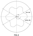
- lobes 14 are not configured as are those of the prior art (solid and sinuous) but rather are configured to provide a greater rigidity on the load side 18 of each stator lobe 14 versus the seal side 20 of each stator lobe 14.
- a skeletal structure 22 is constructed having, in one embodiment just a hollow 24 ( Fig. 3 ) of the lobe 14 and in another embodiment having a number of ribs 26 ( Fig. 2 ). Skeletal structure is defined herein as any configuration of solid portions and open spaces defined between the solid portions to exhibit a framework.
- the hollow 24 is bounded by an operating portion 28 of the lobe 14.
- the ribs 26 extend from one point to another point inside the otherwise hollow space bounded by the operating portion 28 of the lobe 14. As illustrated in Figure 2 , the ribs 26 extend from the tubular portion 12 radially inwardly until they connect to the operating portion of the lobe 14. Other reinforcing structure patterns are also contemplated.
- the load side of the lobe 18 follows a contour that is close to the load surface of the lobe 14. This makes the sealing material 16 thin at this side of the lobe but well supported for high load carrying capability while still providing a sealing function. Conversely, the contour at the sealing side of the lobes 14 is left largely unsupported by the skeletal structure 22.
- the lobes are more asymmetric and the sealing material 16 may have the same thickness throughout. See Figure 4 for a schematic view of an asymmetric lobe pattern.
- the sealing material 16 often is constructed of rubber though other compounds including metal with adjusted material properties such as density, resilience, etc. is also contemplated herein.
- the configuration of the lobes 14 whether symmetric or asymmetric may be optimized to avoid the generation of resonant frequencies during use.
- the ribs 26, (three shown but more or fewer contemplated) are oriented to be substantially normal to the surface of the load side 18 of the lobes 14. This structurally provides great rigidity to the load side of lobe 14 while reducing weight over prior art configurations. As noted, it is contemplated to provide ribs or other structure or shapes in other configurations as well and one purpose of such is to adjust the compliance of the load side of the lobe 14 for applications that may benefit from such.
- the volume between the ribs 26 or the hollow 24 may be employed as a fluid conduit (conveyance and/or cooling)or a conductor conduit (for electric, hydraulic or optical line).
- the surface in some embodiments is randomly roughened, a diamond shaped pattern ( Fig. 5 ), wavy ( Fig. 6 ), having grooves 32 and/or bumps 34 ( Fig. 7 ), etc. for the purpose of increasing adhesion of the material 16 that will be disposed thereon as well as improving the function of the rubber injection process by increasing adhesion and reducing injection pressure and temperature.
- the stator or pump 10 may be created by conventional manufacturing methods but would be laborious to achieve. Therefore the inventors hereof also note that additive manufacturing or 3D printing is highly suited to producing all of the features noted above with respect to the various alternate embodiments of a stator or pump disclosed herein.
- Each of the stator or pump embodiments may be created using one or more of selective laser melting, direct metal laser sintering, direct metal laser melting, selective laser sintering, electron beam manufacturing, direct laser deposition, cold gas processing, laser cladding, direct material deposition, ceramic additive manufacturing, ultrasonic welding, or binder jetting and subsequent sintering, for example in powder bed or nozzle feed or wire feed configurations. The material deposited is bonded together by welding, binding and sintering, etc. Additive manufacturing processes are known to the art and require no specific discussion in connection with this disclosure.
- AM also supports the other adjustments discussed above with respect to density, resilience, compliance, etc. (see above) of the material used to make the stator 10, to wit: one of the operating parameters of the process may be modified to produce a material property in a location within the stator 10 that is different than that material property elsewhere in stator 10. For example, the process of melting may be halted where an opening is to be located. Alternatively or additionally, the process may be altered to change the density of the base material in certain areas to cause a feature to be resilient or compliant.
- changes in one or more parameters of the additive manufacturing process used to create the material may be made. These changes include but are not limited to: varying the energy applied to the feed material by the energy source e.g. laser or electron beam (varying the energy source power including zero power, varying the energy source focus, varying the energy source scanning speed, varying the energy source line spacing) or varying the feed material itself may be employed. More specifically, with respect to energy applied, the energy source being employed, whether e.g. 200, 400, 1000 W or any other energy source power, may be reduced in power at the selected location to reduce the melting of the powdered (or other type) feed material.
- the energy source e.g. laser or electron beam
- the energy source may be reduced in power at the selected location to reduce the melting of the powdered (or other type) feed material.
- Reduction in the amount of melt will change the density of the manufactured part in locations where melting was reduced or eliminated in the case of zero power (which will simply leave feed material unaltered, e.g. still powdered).
- the feed material itself may be altered. This may be accomplished by changing the material supplied at a feed head for powdered feed material or by changing the wire composition in a wire feed process. Processes capable of additive manufacturing with different materials include cold gas processes, energy source cladding or direct laser deposition, for example.
- Materials contemplated for construction of the stator or pump include fine particles of or a wire including metal and/or metal alloy material and may optionally further include plastic, ceramic, and/or organic material. More specifically, material may include, for example, cobalt, nickel, copper, chromium, aluminum, iron, steel, stainless steel, titanium, tungsten, or alloys and mixtures thereof, magnetically responsive materials, polyetheretherketone (PEEKTM), carbon-based materials (e.g., graphite, graphene, diamond, etc.), and/or glass.
- PEEKTM polyetheretherketone
- carbon-based materials e.g., graphite, graphene, diamond, etc.
- materials that may be employed include PA12-MD(Al), PA12-CF, PA11, 18Mar 300/1.2709, 15-5/1.4540, 1.4404 (316L), Alloy 718, Alloy 625, CoCrMo,UNS R31538, Ti6AI4V andAlSi10Mg, Alloy 945x, 17-4/1.4542, Alloy 925, CrMnMoN-steel, CoCrAlloys (STELLITE ® ), CoNiAlloy, MP35 or equivalent, 4140, 4145, WC-Ni, WC-Co, and/or W.
- a metallic-ceramic composite material e.g., a cermet
- these materials may be fine particles of cobalt, nickel, iron, steel, stainless steel, or alloys and mixtures thereof intermixed with fine particles of tungsten carbide, titanium carbide, tantalum carbide, molybdenum carbide, and other metal-carbide ceramic materials.
- a downhole system is schematically illustrated having a stator or pump as disclosed herein disposed therein.
- the system comprises a string 40 disposed in a borehole 42, the string including a stator or pump 10.
- a method for producing a mud motor stator or a pump comprising: creating a computer model of a stator or pump; loading the model into an additive manufacturing apparatus; and operating the additive manufacturing apparatus to produce a physical replica of the model.
Landscapes
- Engineering & Computer Science (AREA)
- Mechanical Engineering (AREA)
- General Engineering & Computer Science (AREA)
- Structures Of Non-Positive Displacement Pumps (AREA)
- Details And Applications Of Rotary Liquid Pumps (AREA)
- Rotary Pumps (AREA)
- Powder Metallurgy (AREA)
Claims (15)
- Verfahren zum Herstellen eines Schlammmotorstators (10), umfassend:Erstellen eines Computermodells des Stators, wobei der Stator eine Designform, umfassend eine Anzahl von Lappen (14), aufweist, von denen mindestens einer eine Skelettstruktur (22) umfasst, wobei die Skelettstruktur (22) asymmetrisch ist und eine Lastseite (18) und eine Dichtungsseite (20) aufweist, wobei die Skelettstruktur konfiguriert ist, um auf der Lastseite (18) eine größere Steifigkeit als auf der Dichtungsseite (20) bereitzustellen;Laden des Computermodells in eine Einrichtung für additive Fertigung; undBetreiben der Einrichtung für additive Fertigung, um das Modell zu verwenden, um eine physische Nachbildung des Modells durch, als Teil eines additiven Fertigungsprozesses, Platzieren von Material und miteinander Verbinden des Materials in einem Muster, das durch die Designform des Stators vorgegeben ist, herzustellen.
- Verfahren nach Anspruch 1, wobei die Form einen röhrenförmigen Außenabschnitt (12) umfasst und sich die Anzahl von Lappen (14) von dem röhrenförmigen Außenabschnitt (12) radial nach innen erstrecken.
- Verfahren nach Anspruch 1 oder 2, wobei das Verbinden durch direktes Metall-Laserschmelzen erfolgt.
- Verfahren nach einem der vorstehenden Ansprüche, wobei der additive Fertigungsprozess einen schichtweisen oder partikelweisen Ansatz umfasst.
- Verfahren nach einem der vorstehenden Ansprüche, wobei das Verbinden durch eines von Schweißen, Binden oder Sintern erfolgt.
- Verfahren nach einem der vorstehenden Ansprüche, wobei ein Betriebsparameter des additiven Fertigungsprozesses modifiziert wird, um an einer Stelle innerhalb des Stators eine Materialeigenschaft, die sich von dieser Materialeigenschaft anderswo in dem Stator unterscheidet, herzustellen.
- Verfahren nach Anspruch 6, wobei der Betriebsparameter des additiven Fertigungsprozesses modifiziert wird, um die Dichte des Materials an bestimmten Stellen zu ändern, um zu bewirken, dass ein Merkmal des Stators federnd oder nachgiebig ist.
- Verfahren nach einem der vorstehenden Ansprüche, wobei das Material feine Partikel aus, oder einen Draht einschließlich, Metall oder Metalllegierung, umfasst.
- Verfahren nach einem der vorstehenden Ansprüche, wobei das Material mindestens eines von Kobalt, Nickel, Kupfer, Chrom, Aluminium, Eisen, Stahl, Edelstahl, Titan und Wolfram umfasst.
- Verfahren nach einem der vorstehenden Ansprüche, wobei das Material mindestens eines von Polyetheretherketon, kohlenstoffbasiertem Material und Glas umfasst.
- Verfahren nach einem der vorstehenden Ansprüche, wobei das Material metallkeramisches Verbundmaterial umfasst.
- Verfahren nach einem der vorstehenden Ansprüche, ferner umfassend ein Anordnen eines Dichtungsmaterials auf der Dichtungsseite (20).
- Verfahren nach einem der vorstehenden Ansprüche, wobei die Anzahl von Lappen (14) Oberflächen einschließen, und wobei mindestens ein Abschnitt dieser Oberflächen konditioniert ist.
- Verfahren nach Anspruch 13, wobei die Konditionierung ein rautenförmiges Muster vorweist.
- Verfahren, umfassend:Herstellen eines Schlammmotorstators unter Verwendung des Verfahrens nach einem der vorstehenden Ansprüche;einschließlich des Schlammmotorstators in einen Strang (40) eines Bohrlochsystems; undAnordnen des Strangs in einem Bohrloch (42).
Applications Claiming Priority (3)
| Application Number | Priority Date | Filing Date | Title |
|---|---|---|---|
| US15/132,008 US10527037B2 (en) | 2016-04-18 | 2016-04-18 | Mud motor stators and pumps and method of making |
| EP17786326.3A EP3445972B1 (de) | 2016-04-18 | 2017-04-05 | Schlammmotorständer und pumpen sowie verfahren zur herstellung |
| PCT/US2017/026124 WO2017184337A1 (en) | 2016-04-18 | 2017-04-05 | Mud motor stators and pumps and method of making |
Related Parent Applications (2)
| Application Number | Title | Priority Date | Filing Date |
|---|---|---|---|
| EP17786326.3A Division EP3445972B1 (de) | 2016-04-18 | 2017-04-05 | Schlammmotorständer und pumpen sowie verfahren zur herstellung |
| EP17786326.3A Division-Into EP3445972B1 (de) | 2016-04-18 | 2017-04-05 | Schlammmotorständer und pumpen sowie verfahren zur herstellung |
Publications (2)
| Publication Number | Publication Date |
|---|---|
| EP4006344A1 EP4006344A1 (de) | 2022-06-01 |
| EP4006344B1 true EP4006344B1 (de) | 2024-10-16 |
Family
ID=60040009
Family Applications (2)
| Application Number | Title | Priority Date | Filing Date |
|---|---|---|---|
| EP21212488.7A Active EP4006344B1 (de) | 2016-04-18 | 2017-04-05 | Verfahren zur herstellung eines schlammmotorstators |
| EP17786326.3A Active EP3445972B1 (de) | 2016-04-18 | 2017-04-05 | Schlammmotorständer und pumpen sowie verfahren zur herstellung |
Family Applications After (1)
| Application Number | Title | Priority Date | Filing Date |
|---|---|---|---|
| EP17786326.3A Active EP3445972B1 (de) | 2016-04-18 | 2017-04-05 | Schlammmotorständer und pumpen sowie verfahren zur herstellung |
Country Status (4)
| Country | Link |
|---|---|
| US (2) | US10527037B2 (de) |
| EP (2) | EP4006344B1 (de) |
| CN (2) | CN111706504B (de) |
| WO (1) | WO2017184337A1 (de) |
Families Citing this family (5)
| Publication number | Priority date | Publication date | Assignee | Title |
|---|---|---|---|---|
| US10527037B2 (en) | 2016-04-18 | 2020-01-07 | Baker Hughes, A Ge Company, Llc | Mud motor stators and pumps and method of making |
| US20180172041A1 (en) * | 2016-12-20 | 2018-06-21 | Baker Hughes Incorporated | Temperature regulated components having cooling channels and method |
| DE102021006414A1 (de) | 2021-12-30 | 2023-07-06 | Seepex Gmbh | Stator für eine Exzenterschneckenpumpe |
| DE202022104701U1 (de) * | 2022-08-19 | 2023-11-22 | Vogelsang Gmbh & Co. Kg | Verdrängerkörper und Pumpengehäuse für eine Verdrängerpumpe |
| DE102023116836A1 (de) * | 2023-06-27 | 2025-01-02 | Netzsch Pumpen & Systeme Gmbh | Stator für eine Pumpe sowie Verfahren zum Herstellen eines Stators für eine Pumpe |
Family Cites Families (53)
| Publication number | Priority date | Publication date | Assignee | Title |
|---|---|---|---|---|
| US3139035A (en) * | 1960-10-24 | 1964-06-30 | Walter J O'connor | Cavity pump mechanism |
| US3975120A (en) | 1973-11-14 | 1976-08-17 | Smith International, Inc. | Wafer elements for progressing cavity stators |
| US3975121A (en) | 1973-11-14 | 1976-08-17 | Smith International, Inc. | Wafer elements for progressing cavity stators |
| DE3576844D1 (de) * | 1984-12-12 | 1990-05-03 | Robert A Barr | Wellenfoermige pumpenanlage. |
| DE4006339C2 (de) | 1990-03-01 | 1994-08-04 | Gd Anker Gmbh & Co Kg | Stator für eine Exzenterschneckenpumpe |
| US5171139A (en) * | 1991-11-26 | 1992-12-15 | Smith International, Inc. | Moineau motor with conduits through the stator |
| US5832604A (en) * | 1995-09-08 | 1998-11-10 | Hydro-Drill, Inc. | Method of manufacturing segmented stators for helical gear pumps and motors |
| US6102681A (en) * | 1997-10-15 | 2000-08-15 | Aps Technology | Stator especially adapted for use in a helicoidal pump/motor |
| DE20014030U1 (de) * | 2000-08-16 | 2001-06-28 | Kunststofftechnik Rodenberg GmbH, 31552 Rodenberg | Förderpumpe zum Fördern von beliebigen Komponenten, insbesondere für Baustoffe |
| US7086532B2 (en) | 2003-07-16 | 2006-08-08 | Allergan, Inc. | Titration/compliance pack with increasing doses |
| US7442019B2 (en) | 2002-10-21 | 2008-10-28 | Noetic Engineering Inc. | Stator of a moineau-pump |
| CA2409054C (en) * | 2002-10-21 | 2009-09-08 | Noetic Engineering Inc., | Method of forming a moineau stator and a moineau stator |
| US6881045B2 (en) | 2003-06-19 | 2005-04-19 | Robbins & Myers Energy Systems, L.P. | Progressive cavity pump/motor |
| US7192260B2 (en) | 2003-10-09 | 2007-03-20 | Lehr Precision, Inc. | Progressive cavity pump/motor stator, and apparatus and method to manufacture same by electrochemical machining |
| CA2543554C (en) * | 2003-10-27 | 2010-03-09 | Dyna-Drill Technologies, Inc. | Asymmetric contouring of elastomer liner on lobes in a moineau style power section stator |
| US7621167B2 (en) | 2004-05-20 | 2009-11-24 | Gilbert Staffend | Method of forming a rotary device |
| US7517202B2 (en) | 2005-01-12 | 2009-04-14 | Smith International, Inc. | Multiple elastomer layer progressing cavity stators |
| US7396220B2 (en) | 2005-02-11 | 2008-07-08 | Dyna-Drill Technologies, Inc. | Progressing cavity stator including at least one cast longitudinal section |
| US7972129B2 (en) | 2005-09-16 | 2011-07-05 | O'donoghue Joseph | Compound tooling system for molding applications |
| EP2019905A2 (de) | 2006-04-28 | 2009-02-04 | Halliburton Energy Services, Inc. | Formen und verfahren zur formherstellung in zusammenhang mit der herstellung von drehbohrern und anderen bohrwerkzeugen |
| US9163629B2 (en) * | 2006-07-31 | 2015-10-20 | Schlumberger Technology Corporation | Controlled thickness resilient material lined stator and method of forming |
| US7739792B2 (en) * | 2006-07-31 | 2010-06-22 | Schlumberger Technology Corporation | Method of forming controlled thickness resilient material lined stator |
| US7878774B2 (en) | 2007-06-05 | 2011-02-01 | Smith International, Inc. | Moineau stator including a skeletal reinforcement |
| US7950914B2 (en) | 2007-06-05 | 2011-05-31 | Smith International, Inc. | Braze or solder reinforced Moineau stator |
| DE102007033434A1 (de) | 2007-07-18 | 2009-01-22 | Voxeljet Technology Gmbh | Verfahren zum Herstellen dreidimensionaler Bauteile |
| US20090152009A1 (en) * | 2007-12-18 | 2009-06-18 | Halliburton Energy Services, Inc., A Delaware Corporation | Nano particle reinforced polymer element for stator and rotor assembly |
| US8197241B2 (en) | 2007-12-18 | 2012-06-12 | Schlumberger Technology Corporation | Nanocomposite Moineau device |
| US7941906B2 (en) * | 2007-12-31 | 2011-05-17 | Schlumberger Technology Corporation | Progressive cavity apparatus with transducer and methods of forming and use |
| DE102008043623A1 (de) | 2008-11-10 | 2010-05-12 | Friedrich-Alexander-Universität Erlangen-Nürnberg | Auxetisches Material |
| CN201539210U (zh) | 2009-10-01 | 2010-08-04 | 邹城市东远石油机械有限公司 | 螺杆钻具的骨架式定子及带有骨架式定子的螺杆钻具 |
| GB0922488D0 (en) * | 2009-12-23 | 2010-02-03 | Advanced Interactive Materials | Improvements in or relating to hot isostatic pressing |
| WO2012024215A2 (en) * | 2010-08-16 | 2012-02-23 | National Oilwell Varco, L.P. | Reinforced stators and fabrication methods |
| DE102010040261A1 (de) | 2010-09-03 | 2012-03-08 | Eos Gmbh Electro Optical Systems | Verfahren zum Herstellen eines dreidimensionalen Objekts mit einer internen Struktur |
| GB201019614D0 (en) * | 2010-11-19 | 2010-12-29 | Eatec Ltd | Apparatus and method for controlling or limiting rotor orbit in moving cavity motors and pumps |
| GB2527213B (en) | 2010-11-29 | 2016-03-02 | Halliburton Energy Services Inc | 3D-Printer for molding downhole equipment |
| TWI576038B (zh) * | 2011-07-13 | 2017-03-21 | 鴻準精密工業股份有限公司 | 散熱裝置 |
| US20130052067A1 (en) | 2011-08-26 | 2013-02-28 | Baker Hughes Incorporated | Downhole Motors and Pumps with Improved Stators and Methods of Making and Using Same |
| US8888474B2 (en) | 2011-09-08 | 2014-11-18 | Baker Hughes Incorporated | Downhole motors and pumps with asymmetric lobes |
| US9228584B2 (en) * | 2011-11-10 | 2016-01-05 | Schlumberger Technology Corporation | Reinforced directional drilling assemblies and methods of forming same |
| DE102012000466B3 (de) | 2012-01-13 | 2013-04-18 | Fraunhofer-Gesellschaft zur Förderung der angewandten Forschung e.V. | Verfahren zur Herstellung von Bauteilen mit filigranen Strukturen und dessen Verwendung |
| GB2499613B (en) * | 2012-02-22 | 2017-11-01 | Nat Oilwell Varco Lp | Stator for progressive cavity pump/motor |
| DE102012008761B4 (de) * | 2012-05-05 | 2016-01-21 | Netzsch Pumpen & Systeme Gmbh | Geteilter Statormantel |
| US20130310961A1 (en) | 2012-05-15 | 2013-11-21 | Schlumberger Technology Corporation | Addititve manufacturing of components for downhole wireline, tubing and drill pipe conveyed tools |
| DE102012012076A1 (de) * | 2012-06-13 | 2013-12-19 | Arnold Jäger Holding GmbH | Stator einer Exzenterschneckenpumpe |
| US9419502B2 (en) | 2012-08-03 | 2016-08-16 | Hamilton Sundstrand Corporation | Additive manufacturing of a component having a laminated stack of layers |
| US8985977B2 (en) | 2012-09-06 | 2015-03-24 | Baker Hughes Incorporated | Asymmetric lobes for motors and pumps |
| CN203009284U (zh) * | 2012-11-15 | 2013-06-19 | 石白妮 | 双定子等壁厚螺杆衬套副 |
| EP2973958A4 (de) * | 2013-03-13 | 2016-09-21 | Services Petroliers Schlumberger | Massiv verstärkter elastomerer stator |
| DE102013108493A1 (de) * | 2013-08-07 | 2015-02-12 | Netzsch Pumpen & Systeme Gmbh | System zur Förderung flüssiger Medien aus einem Bohrloch sowie Verfahren zur Installation einer als Exzenterschneckenpumpe ausgebildeten Pumpeinheit in einem Bohrloch |
| CN104595182B (zh) * | 2014-11-28 | 2019-05-10 | 浙江歌瑞新材料有限公司 | 一种使用fep制作的螺杆钻具定子及应用于该定子的改性fep |
| US9162279B1 (en) | 2015-02-26 | 2015-10-20 | Madesolid, Inc. | Solid to gas phase change material for additive manufacturing |
| US10590929B2 (en) * | 2015-05-04 | 2020-03-17 | Penn United Technologies, Inc. | Method of coupling stator/rotor laminates |
| US10527037B2 (en) | 2016-04-18 | 2020-01-07 | Baker Hughes, A Ge Company, Llc | Mud motor stators and pumps and method of making |
-
2016
- 2016-04-18 US US15/132,008 patent/US10527037B2/en active Active
-
2017
- 2017-04-05 EP EP21212488.7A patent/EP4006344B1/de active Active
- 2017-04-05 EP EP17786326.3A patent/EP3445972B1/de active Active
- 2017-04-05 CN CN202010579047.3A patent/CN111706504B/zh active Active
- 2017-04-05 WO PCT/US2017/026124 patent/WO2017184337A1/en not_active Ceased
- 2017-04-05 CN CN201780023527.8A patent/CN109072903B/zh active Active
-
2019
- 2019-11-27 US US16/698,221 patent/US11192211B2/en active Active
Also Published As
| Publication number | Publication date |
|---|---|
| EP3445972B1 (de) | 2022-01-19 |
| US20200109708A1 (en) | 2020-04-09 |
| WO2017184337A1 (en) | 2017-10-26 |
| CN109072903A (zh) | 2018-12-21 |
| EP4006344A1 (de) | 2022-06-01 |
| CN111706504B (zh) | 2022-05-13 |
| CN111706504A (zh) | 2020-09-25 |
| EP3445972A4 (de) | 2019-11-06 |
| EP3445972A1 (de) | 2019-02-27 |
| CN109072903B (zh) | 2021-01-05 |
| US10527037B2 (en) | 2020-01-07 |
| US11192211B2 (en) | 2021-12-07 |
| US20170298933A1 (en) | 2017-10-19 |
Similar Documents
| Publication | Publication Date | Title |
|---|---|---|
| US11192211B2 (en) | Mud motor stators and pumps and method of making | |
| US10386801B2 (en) | Methods of forming and methods of repairing earth-boring tools | |
| CN101356031B (zh) | 钻地旋转钻头和制造具有颗粒基体复合钻头体的钻地旋转钻头的方法 | |
| US11400533B2 (en) | Carbide wear surface and method of manufacture | |
| WO2021030695A1 (en) | Additively manufactured extruder component including lattice | |
| WO2009018427A1 (en) | Bonding agents for improved sintering of earth-boring tools, methods of forming earth-boring tools and resulting structures | |
| CN107206500A (zh) | 金属基复合材料工具所用的网状增强件 | |
| KR101469402B1 (ko) | 회전 드릴용 비트의 제조 방법 | |
| EP0902159A2 (de) | Schneidelement mit nicht-planer, nicht linearer Zwischenfläche | |
| US9765819B1 (en) | Bearing assemblies, apparatuses, and motor assemblies using the same | |
| CN108138542B (zh) | 形成和修复钻地工具的方法 | |
| US9890595B2 (en) | Methods of forming and methods of repairing earth boring-tools | |
| US8778259B2 (en) | Self-renewing cutting surface, tool and method for making same using powder metallurgy and densification techniques | |
| US20140262542A1 (en) | Downhole tools including ternary boride-based cermet and methods of making the same | |
| CN105593454B (zh) | 用于改善附接性的增强pcd切割器凹口表面几何结构 | |
| WO2019164534A1 (en) | Variable density downhole devices | |
| US10717129B2 (en) | Pre-diffused mandrel coating to provide enhanced bonding between metallic and composite components | |
| US20220297183A1 (en) | Additive manufacturing of components with functionally graded properties | |
| CA3038437A1 (fr) | Rock-cutting tool and method for mine and oil drilling |
Legal Events
| Date | Code | Title | Description |
|---|---|---|---|
| PUAI | Public reference made under article 153(3) epc to a published international application that has entered the european phase |
Free format text: ORIGINAL CODE: 0009012 |
|
| STAA | Information on the status of an ep patent application or granted ep patent |
Free format text: STATUS: THE APPLICATION HAS BEEN PUBLISHED |
|
| AC | Divisional application: reference to earlier application |
Ref document number: 3445972 Country of ref document: EP Kind code of ref document: P |
|
| AK | Designated contracting states |
Kind code of ref document: A1 Designated state(s): AL AT BE BG CH CY CZ DE DK EE ES FI FR GB GR HR HU IE IS IT LI LT LU LV MC MK MT NL NO PL PT RO RS SE SI SK SM TR |
|
| STAA | Information on the status of an ep patent application or granted ep patent |
Free format text: STATUS: REQUEST FOR EXAMINATION WAS MADE |
|
| 17P | Request for examination filed |
Effective date: 20221201 |
|
| RBV | Designated contracting states (corrected) |
Designated state(s): AL AT BE BG CH CY CZ DE DK EE ES FI FR GB GR HR HU IE IS IT LI LT LU LV MC MK MT NL NO PL PT RO RS SE SI SK SM TR |
|
| P01 | Opt-out of the competence of the unified patent court (upc) registered |
Effective date: 20230526 |
|
| GRAP | Despatch of communication of intention to grant a patent |
Free format text: ORIGINAL CODE: EPIDOSNIGR1 |
|
| STAA | Information on the status of an ep patent application or granted ep patent |
Free format text: STATUS: GRANT OF PATENT IS INTENDED |
|
| INTG | Intention to grant announced |
Effective date: 20240618 |
|
| GRAS | Grant fee paid |
Free format text: ORIGINAL CODE: EPIDOSNIGR3 |
|
| GRAA | (expected) grant |
Free format text: ORIGINAL CODE: 0009210 |
|
| STAA | Information on the status of an ep patent application or granted ep patent |
Free format text: STATUS: THE PATENT HAS BEEN GRANTED |
|
| AC | Divisional application: reference to earlier application |
Ref document number: 3445972 Country of ref document: EP Kind code of ref document: P |
|
| AK | Designated contracting states |
Kind code of ref document: B1 Designated state(s): AL AT BE BG CH CY CZ DE DK EE ES FI FR GB GR HR HU IE IS IT LI LT LU LV MC MK MT NL NO PL PT RO RS SE SI SK SM TR |
|
| REG | Reference to a national code |
Ref country code: GB Ref legal event code: FG4D |
|
| REG | Reference to a national code |
Ref country code: CH Ref legal event code: EP |
|
| REG | Reference to a national code |
Ref country code: IE Ref legal event code: FG4D |
|
| REG | Reference to a national code |
Ref country code: DE Ref legal event code: R096 Ref document number: 602017085605 Country of ref document: DE |
|
| REG | Reference to a national code |
Ref country code: LT Ref legal event code: MG9D |
|
| REG | Reference to a national code |
Ref country code: NL Ref legal event code: MP Effective date: 20241016 |
|
| REG | Reference to a national code |
Ref country code: AT Ref legal event code: MK05 Ref document number: 1733103 Country of ref document: AT Kind code of ref document: T Effective date: 20241016 |
|
| PG25 | Lapsed in a contracting state [announced via postgrant information from national office to epo] |
Ref country code: NL Free format text: LAPSE BECAUSE OF FAILURE TO SUBMIT A TRANSLATION OF THE DESCRIPTION OR TO PAY THE FEE WITHIN THE PRESCRIBED TIME-LIMIT Effective date: 20241016 |
|
| PG25 | Lapsed in a contracting state [announced via postgrant information from national office to epo] |
Ref country code: NL Free format text: LAPSE BECAUSE OF FAILURE TO SUBMIT A TRANSLATION OF THE DESCRIPTION OR TO PAY THE FEE WITHIN THE PRESCRIBED TIME-LIMIT Effective date: 20241016 |
|
| PG25 | Lapsed in a contracting state [announced via postgrant information from national office to epo] |
Ref country code: PT Free format text: LAPSE BECAUSE OF FAILURE TO SUBMIT A TRANSLATION OF THE DESCRIPTION OR TO PAY THE FEE WITHIN THE PRESCRIBED TIME-LIMIT Effective date: 20250217 Ref country code: IS Free format text: LAPSE BECAUSE OF FAILURE TO SUBMIT A TRANSLATION OF THE DESCRIPTION OR TO PAY THE FEE WITHIN THE PRESCRIBED TIME-LIMIT Effective date: 20250216 Ref country code: HR Free format text: LAPSE BECAUSE OF FAILURE TO SUBMIT A TRANSLATION OF THE DESCRIPTION OR TO PAY THE FEE WITHIN THE PRESCRIBED TIME-LIMIT Effective date: 20241016 |
|
| PG25 | Lapsed in a contracting state [announced via postgrant information from national office to epo] |
Ref country code: FI Free format text: LAPSE BECAUSE OF FAILURE TO SUBMIT A TRANSLATION OF THE DESCRIPTION OR TO PAY THE FEE WITHIN THE PRESCRIBED TIME-LIMIT Effective date: 20241016 |
|
| PG25 | Lapsed in a contracting state [announced via postgrant information from national office to epo] |
Ref country code: BG Free format text: LAPSE BECAUSE OF FAILURE TO SUBMIT A TRANSLATION OF THE DESCRIPTION OR TO PAY THE FEE WITHIN THE PRESCRIBED TIME-LIMIT Effective date: 20241016 |
|
| PG25 | Lapsed in a contracting state [announced via postgrant information from national office to epo] |
Ref country code: ES Free format text: LAPSE BECAUSE OF FAILURE TO SUBMIT A TRANSLATION OF THE DESCRIPTION OR TO PAY THE FEE WITHIN THE PRESCRIBED TIME-LIMIT Effective date: 20241016 |
|
| PG25 | Lapsed in a contracting state [announced via postgrant information from national office to epo] |
Ref country code: LV Free format text: LAPSE BECAUSE OF FAILURE TO SUBMIT A TRANSLATION OF THE DESCRIPTION OR TO PAY THE FEE WITHIN THE PRESCRIBED TIME-LIMIT Effective date: 20241016 Ref country code: GR Free format text: LAPSE BECAUSE OF FAILURE TO SUBMIT A TRANSLATION OF THE DESCRIPTION OR TO PAY THE FEE WITHIN THE PRESCRIBED TIME-LIMIT Effective date: 20250117 Ref country code: AT Free format text: LAPSE BECAUSE OF FAILURE TO SUBMIT A TRANSLATION OF THE DESCRIPTION OR TO PAY THE FEE WITHIN THE PRESCRIBED TIME-LIMIT Effective date: 20241016 |
|
| PG25 | Lapsed in a contracting state [announced via postgrant information from national office to epo] |
Ref country code: PL Free format text: LAPSE BECAUSE OF FAILURE TO SUBMIT A TRANSLATION OF THE DESCRIPTION OR TO PAY THE FEE WITHIN THE PRESCRIBED TIME-LIMIT Effective date: 20241016 |
|
| PG25 | Lapsed in a contracting state [announced via postgrant information from national office to epo] |
Ref country code: RS Free format text: LAPSE BECAUSE OF FAILURE TO SUBMIT A TRANSLATION OF THE DESCRIPTION OR TO PAY THE FEE WITHIN THE PRESCRIBED TIME-LIMIT Effective date: 20250116 |
|
| PG25 | Lapsed in a contracting state [announced via postgrant information from national office to epo] |
Ref country code: SM Free format text: LAPSE BECAUSE OF FAILURE TO SUBMIT A TRANSLATION OF THE DESCRIPTION OR TO PAY THE FEE WITHIN THE PRESCRIBED TIME-LIMIT Effective date: 20241016 |
|
| PG25 | Lapsed in a contracting state [announced via postgrant information from national office to epo] |
Ref country code: DK Free format text: LAPSE BECAUSE OF FAILURE TO SUBMIT A TRANSLATION OF THE DESCRIPTION OR TO PAY THE FEE WITHIN THE PRESCRIBED TIME-LIMIT Effective date: 20241016 |
|
| REG | Reference to a national code |
Ref country code: DE Ref legal event code: R097 Ref document number: 602017085605 Country of ref document: DE |
|
| PG25 | Lapsed in a contracting state [announced via postgrant information from national office to epo] |
Ref country code: EE Free format text: LAPSE BECAUSE OF FAILURE TO SUBMIT A TRANSLATION OF THE DESCRIPTION OR TO PAY THE FEE WITHIN THE PRESCRIBED TIME-LIMIT Effective date: 20241016 |
|
| PG25 | Lapsed in a contracting state [announced via postgrant information from national office to epo] |
Ref country code: RO Free format text: LAPSE BECAUSE OF FAILURE TO SUBMIT A TRANSLATION OF THE DESCRIPTION OR TO PAY THE FEE WITHIN THE PRESCRIBED TIME-LIMIT Effective date: 20241016 |
|
| PG25 | Lapsed in a contracting state [announced via postgrant information from national office to epo] |
Ref country code: SK Free format text: LAPSE BECAUSE OF FAILURE TO SUBMIT A TRANSLATION OF THE DESCRIPTION OR TO PAY THE FEE WITHIN THE PRESCRIBED TIME-LIMIT Effective date: 20241016 |
|
| PG25 | Lapsed in a contracting state [announced via postgrant information from national office to epo] |
Ref country code: CZ Free format text: LAPSE BECAUSE OF FAILURE TO SUBMIT A TRANSLATION OF THE DESCRIPTION OR TO PAY THE FEE WITHIN THE PRESCRIBED TIME-LIMIT Effective date: 20241016 |
|
| PG25 | Lapsed in a contracting state [announced via postgrant information from national office to epo] |
Ref country code: IT Free format text: LAPSE BECAUSE OF FAILURE TO SUBMIT A TRANSLATION OF THE DESCRIPTION OR TO PAY THE FEE WITHIN THE PRESCRIBED TIME-LIMIT Effective date: 20241016 |
|
| PLBE | No opposition filed within time limit |
Free format text: ORIGINAL CODE: 0009261 |
|
| STAA | Information on the status of an ep patent application or granted ep patent |
Free format text: STATUS: NO OPPOSITION FILED WITHIN TIME LIMIT |
|
| PG25 | Lapsed in a contracting state [announced via postgrant information from national office to epo] |
Ref country code: SE Free format text: LAPSE BECAUSE OF FAILURE TO SUBMIT A TRANSLATION OF THE DESCRIPTION OR TO PAY THE FEE WITHIN THE PRESCRIBED TIME-LIMIT Effective date: 20241016 |
|
| 26N | No opposition filed |
Effective date: 20250717 |
|
| REG | Reference to a national code |
Ref country code: DE Ref legal event code: R119 Ref document number: 602017085605 Country of ref document: DE |
|
| REG | Reference to a national code |
Ref country code: CH Ref legal event code: H13 Free format text: ST27 STATUS EVENT CODE: U-0-0-H10-H13 (AS PROVIDED BY THE NATIONAL OFFICE) Effective date: 20251125 |
|
| PG25 | Lapsed in a contracting state [announced via postgrant information from national office to epo] |
Ref country code: LU Free format text: LAPSE BECAUSE OF NON-PAYMENT OF DUE FEES Effective date: 20250405 |
|
| PG25 | Lapsed in a contracting state [announced via postgrant information from national office to epo] |
Ref country code: MC Free format text: LAPSE BECAUSE OF FAILURE TO SUBMIT A TRANSLATION OF THE DESCRIPTION OR TO PAY THE FEE WITHIN THE PRESCRIBED TIME-LIMIT Effective date: 20241016 |
|
| REG | Reference to a national code |
Ref country code: BE Ref legal event code: MM Effective date: 20250430 |
|
| PG25 | Lapsed in a contracting state [announced via postgrant information from national office to epo] |
Ref country code: DE Free format text: LAPSE BECAUSE OF NON-PAYMENT OF DUE FEES Effective date: 20251104 |
|
| PG25 | Lapsed in a contracting state [announced via postgrant information from national office to epo] |
Ref country code: FR Free format text: LAPSE BECAUSE OF NON-PAYMENT OF DUE FEES Effective date: 20250430 |
|
| PG25 | Lapsed in a contracting state [announced via postgrant information from national office to epo] |
Ref country code: BE Free format text: LAPSE BECAUSE OF NON-PAYMENT OF DUE FEES Effective date: 20250430 |
|
| PG25 | Lapsed in a contracting state [announced via postgrant information from national office to epo] |
Ref country code: CH Free format text: LAPSE BECAUSE OF NON-PAYMENT OF DUE FEES Effective date: 20250430 |
|
| PGFP | Annual fee paid to national office [announced via postgrant information from national office to epo] |
Ref country code: GB Payment date: 20260319 Year of fee payment: 10 |
|
| PG25 | Lapsed in a contracting state [announced via postgrant information from national office to epo] |
Ref country code: IE Free format text: LAPSE BECAUSE OF NON-PAYMENT OF DUE FEES Effective date: 20250405 |
|
| PGFP | Annual fee paid to national office [announced via postgrant information from national office to epo] |
Ref country code: NO Payment date: 20260320 Year of fee payment: 10 |