EP4006348B1 - Ventilateur doté d'un moteur à rotor externe et canal de refroidissement destiné au refroidissement de l'électronique du moteur et des composants d'entraînement du moteur - Google Patents
Ventilateur doté d'un moteur à rotor externe et canal de refroidissement destiné au refroidissement de l'électronique du moteur et des composants d'entraînement du moteur Download PDFInfo
- Publication number
- EP4006348B1 EP4006348B1 EP22152257.6A EP22152257A EP4006348B1 EP 4006348 B1 EP4006348 B1 EP 4006348B1 EP 22152257 A EP22152257 A EP 22152257A EP 4006348 B1 EP4006348 B1 EP 4006348B1
- Authority
- EP
- European Patent Office
- Prior art keywords
- motor
- fan
- electronics
- stator
- cooling
- Prior art date
- Legal status (The legal status is an assumption and is not a legal conclusion. Google has not performed a legal analysis and makes no representation as to the accuracy of the status listed.)
- Active
Links
Images


Classifications
-
- H—ELECTRICITY
- H02—GENERATION; CONVERSION OR DISTRIBUTION OF ELECTRIC POWER
- H02K—DYNAMO-ELECTRIC MACHINES
- H02K9/00—Arrangements for cooling or ventilating
- H02K9/02—Arrangements for cooling or ventilating by ambient air flowing through the machine
- H02K9/04—Arrangements for cooling or ventilating by ambient air flowing through the machine having means for generating a flow of cooling medium
- H02K9/06—Arrangements for cooling or ventilating by ambient air flowing through the machine having means for generating a flow of cooling medium with fans or impellers driven by the machine shaft
-
- F—MECHANICAL ENGINEERING; LIGHTING; HEATING; WEAPONS; BLASTING
- F04—POSITIVE - DISPLACEMENT MACHINES FOR LIQUIDS; PUMPS FOR LIQUIDS OR ELASTIC FLUIDS
- F04D—NON-POSITIVE-DISPLACEMENT PUMPS
- F04D25/00—Pumping installations or systems
- F04D25/02—Units comprising pumps and their driving means
- F04D25/08—Units comprising pumps and their driving means the working fluid being air, e.g. for ventilation
- F04D25/082—Units comprising pumps and their driving means the working fluid being air, e.g. for ventilation the unit having provision for cooling the motor
-
- F—MECHANICAL ENGINEERING; LIGHTING; HEATING; WEAPONS; BLASTING
- F04—POSITIVE - DISPLACEMENT MACHINES FOR LIQUIDS; PUMPS FOR LIQUIDS OR ELASTIC FLUIDS
- F04D—NON-POSITIVE-DISPLACEMENT PUMPS
- F04D29/00—Details, component parts, or accessories
- F04D29/58—Cooling; Heating; Diminishing heat transfer
- F04D29/582—Cooling; Heating; Diminishing heat transfer specially adapted for elastic fluid pumps
- F04D29/584—Cooling; Heating; Diminishing heat transfer specially adapted for elastic fluid pumps cooling or heating the machine
-
- F—MECHANICAL ENGINEERING; LIGHTING; HEATING; WEAPONS; BLASTING
- F04—POSITIVE - DISPLACEMENT MACHINES FOR LIQUIDS; PUMPS FOR LIQUIDS OR ELASTIC FLUIDS
- F04D—NON-POSITIVE-DISPLACEMENT PUMPS
- F04D17/00—Radial-flow pumps, e.g. centrifugal pumps; Helico-centrifugal pumps
- F04D17/08—Centrifugal pumps
- F04D17/16—Centrifugal pumps for displacing without appreciable compression
-
- F—MECHANICAL ENGINEERING; LIGHTING; HEATING; WEAPONS; BLASTING
- F04—POSITIVE - DISPLACEMENT MACHINES FOR LIQUIDS; PUMPS FOR LIQUIDS OR ELASTIC FLUIDS
- F04D—NON-POSITIVE-DISPLACEMENT PUMPS
- F04D25/00—Pumping installations or systems
- F04D25/02—Units comprising pumps and their driving means
- F04D25/06—Units comprising pumps and their driving means the pump being electrically driven
- F04D25/0606—Units comprising pumps and their driving means the pump being electrically driven the electric motor being specially adapted for integration in the pump
- F04D25/0613—Units comprising pumps and their driving means the pump being electrically driven the electric motor being specially adapted for integration in the pump the electric motor being of the inside-out type, i.e. the rotor is arranged radially outside a central stator
-
- F—MECHANICAL ENGINEERING; LIGHTING; HEATING; WEAPONS; BLASTING
- F04—POSITIVE - DISPLACEMENT MACHINES FOR LIQUIDS; PUMPS FOR LIQUIDS OR ELASTIC FLUIDS
- F04D—NON-POSITIVE-DISPLACEMENT PUMPS
- F04D25/00—Pumping installations or systems
- F04D25/02—Units comprising pumps and their driving means
- F04D25/06—Units comprising pumps and their driving means the pump being electrically driven
- F04D25/0606—Units comprising pumps and their driving means the pump being electrically driven the electric motor being specially adapted for integration in the pump
- F04D25/0613—Units comprising pumps and their driving means the pump being electrically driven the electric motor being specially adapted for integration in the pump the electric motor being of the inside-out type, i.e. the rotor is arranged radially outside a central stator
- F04D25/064—Details of the rotor
-
- F—MECHANICAL ENGINEERING; LIGHTING; HEATING; WEAPONS; BLASTING
- F04—POSITIVE - DISPLACEMENT MACHINES FOR LIQUIDS; PUMPS FOR LIQUIDS OR ELASTIC FLUIDS
- F04D—NON-POSITIVE-DISPLACEMENT PUMPS
- F04D25/00—Pumping installations or systems
- F04D25/02—Units comprising pumps and their driving means
- F04D25/06—Units comprising pumps and their driving means the pump being electrically driven
- F04D25/0606—Units comprising pumps and their driving means the pump being electrically driven the electric motor being specially adapted for integration in the pump
- F04D25/0613—Units comprising pumps and their driving means the pump being electrically driven the electric motor being specially adapted for integration in the pump the electric motor being of the inside-out type, i.e. the rotor is arranged radially outside a central stator
- F04D25/0646—Details of the stator
-
- F—MECHANICAL ENGINEERING; LIGHTING; HEATING; WEAPONS; BLASTING
- F04—POSITIVE - DISPLACEMENT MACHINES FOR LIQUIDS; PUMPS FOR LIQUIDS OR ELASTIC FLUIDS
- F04D—NON-POSITIVE-DISPLACEMENT PUMPS
- F04D29/00—Details, component parts, or accessories
- F04D29/05—Shafts or bearings, or assemblies thereof, specially adapted for elastic fluid pumps
- F04D29/056—Bearings
-
- F—MECHANICAL ENGINEERING; LIGHTING; HEATING; WEAPONS; BLASTING
- F04—POSITIVE - DISPLACEMENT MACHINES FOR LIQUIDS; PUMPS FOR LIQUIDS OR ELASTIC FLUIDS
- F04D—NON-POSITIVE-DISPLACEMENT PUMPS
- F04D29/00—Details, component parts, or accessories
- F04D29/58—Cooling; Heating; Diminishing heat transfer
- F04D29/5806—Cooling the drive system
-
- F—MECHANICAL ENGINEERING; LIGHTING; HEATING; WEAPONS; BLASTING
- F04—POSITIVE - DISPLACEMENT MACHINES FOR LIQUIDS; PUMPS FOR LIQUIDS OR ELASTIC FLUIDS
- F04D—NON-POSITIVE-DISPLACEMENT PUMPS
- F04D29/00—Details, component parts, or accessories
- F04D29/58—Cooling; Heating; Diminishing heat transfer
- F04D29/5813—Cooling the control unit
-
- H—ELECTRICITY
- H02—GENERATION; CONVERSION OR DISTRIBUTION OF ELECTRIC POWER
- H02K—DYNAMO-ELECTRIC MACHINES
- H02K9/00—Arrangements for cooling or ventilating
- H02K9/22—Arrangements for cooling or ventilating by solid heat conducting material embedded in, or arranged in contact with, the stator or rotor, e.g. heat bridges
Definitions
- the invention relates to a fan with an external rotor motor and a cooling channel for cooling both the motor electronics and motor drive components.
- an active cooling wheel is installed on the rotor in addition to the fan wheel driven by the external rotor motor, which generates its own cooling energy during the rotation of the rotor. Cooling air flow is generated, which is actively guided along the engine electronics.
- cooling of motor drive components In addition to cooling the motor electronics, cooling of motor drive components, such as the rotor, stator or motor bearings, is also desired.
- the invention is therefore based on the object of providing a fan which, even at low speeds, has improved cooling of the overall arrangement of the external rotor motor with regard to its motor electronics and motor drive components, with the lowest possible and most cost-effective material expenditure.
- the noise development should be comparatively low.
- a fan with an external rotor motor in which the external rotor motor has a rotor rotating about a rotation axis in a motor section, which rotor is designed to radially accommodate a Fan wheel.
- the external rotor motor also provides motor electronics arranged in an electronics section housed in an electronics housing, wherein the motor section and the electronics section are arranged along the axis of rotation, preferably axially, alternatively radially, adjacent to one another.
- the fan generates a pressure difference via the fan wheel between its suction side, which is preferably assigned to the rotor, and its pressure side, which is preferably assigned to the motor electronics.
- a continuous cooling channel runs from a pressure-side inlet opening on the electronics housing along the motor electronics and at least in sections along the rotor to a suction-side outlet opening in the motor section, so that during operation a cooling air flow through the cooling channel can be generated exclusively passively by the pressure difference generated by the fan wheel in order to cool both the electronics section and the motor section.
- the pressure side and suction side depend on the flow direction of the fan. However, the cooling air flow always occurs from the pressure side to the suction side.
- the inlet opening on the electronics housing described above is then the outlet opening in the case of an inverse flow direction, and the outlet opening in the motor section then becomes the inlet opening.
- the fan wheel When the fan is operating, the fan wheel sucks in air on the suction side, creating a negative pressure on the suction side, and blows it out on the pressure side, where an overpressure is created. This results in a pressure difference ⁇ p between the suction side and the pressure side.
- the pressure difference creates a compensating flow through the cooling channel, which is used as a passive cooling air flow.
- the cooling air flow is sucked in on the suction side at the outlet opening and conveyed through the cooling channel, with the pressure difference being generated by the fan wheel on the suction side of the fan.
- a "passively" generated cooling air flow through the cooling channel is defined as the distinction from an active air flow generated by an active cooling wheel rotating during operation. Active cooling wheels generate noise, especially at higher speeds. This can be prevented by purely passive cooling.
- An axial section serves to demarcate the electronics section from the motor section, where the motor electronics components that protrude furthest towards the rotor end.
- the motor electronics are often placed axially on the motor drive components. This creates a separation between the two components.
- one design variant provides that several cooling fins are formed on the electronics housing, which extend axially and radially from the inlet opening into the cooling channel and form a channel wall surface of the cooling channel.
- the cooling fins also preferably form the inlet opening on the electronics housing. The increased surface area achieved by the cooling fins and the positioning directly at the inlet opening lead to favorable and effective heat dissipation via the cooling air flow through the cooling channel.
- the fan is further preferably characterized in that the rotor has a rotor housing, preferably designed as a rotor bell, and the outflow opening is formed in the region of an axial end face of the rotor housing.
- the outflow is therefore preferably axial, but can also be provided on the outer surface of the rotor housing or at the transition between the axial end face and the outer surface and thus have an at least partially radial outflow direction.
- the fan wheel for this design has an impeller base plate with impeller blades formed on it, with the outlet opening formed in the impeller base plate.
- the cooling channel therefore does not extend over the entire axial length in the motor section, but is already slid to the outside of the rotor at the impeller base plate.
- the external rotor motor in the motor section has a stator bushing with a stator package and motor windings as well as stator cooling fins distributed in the circumferential direction, wherein the cooling channel also runs along the stator cooling fins.
- the solution for radial fans is particularly designed so that the impeller base plate runs axially adjacent to the stator cooling fins that extend axially to the impeller base plate, so that the cooling air flow can be guided axially over the stator cooling fins to the outlet opening in the impeller base plate.
- This solution also ensures sufficient cooling performance in the motor section for radial fans in addition to cooling the motor electronics in the electronics section, since the stator cooling fins are arranged as a motor component in the motor section.
- the external rotor motor has a stator bushing with a stator package and motor windings in the motor section, as well as stator cooling fins distributed in the circumferential direction, with the cooling air flow running directly adjacent to the stator cooling fins and along the stator package.
- the cooling air flow can flow freely through the motor section, taking the path of least resistance, or be guided along certain components in a cooling channel.
- the possibility of forming the outlet opening on the rotor or rotor housing itself means that the cooling air flow inside the rotor can be guided directly along the components that heat up during operation.
- a favorable embodiment of the fan is characterized in that the cooling channel in a transition from the electronics section to the motor section is closed or essentially closed by a stationary or rotatable cover.
- Essentially closed means that no complete seal is provided.
- the cover can be designed in a labyrinth-shaped manner in the sense of a labyrinth seal in order to have to accept as little leakage as possible.
- the cover is stationary or rotates during operation.
- the cover forms an outer surface of the external rotor motor.
- a further development of the fan provides that the cooling channel has several changes of direction in the course from the inlet opening to the outlet opening, so that the cooling air flow is redirected several times. This allows the cooling to be directed along the components to be cooled and thus the cooling performance to be increased.
- the outlet opening on the rotor housing is axially spaced from the fan wheel. This helps to ensure a sufficient pressure difference and thus the suction effect at the outlet opening.
- one design of the fan provides that the cooling channel runs circumferentially in the electronics section and the motor section in a locally limited manner. The space required for cooling is thus limited. The structure of the external rotor motor remains compact.
- the rotor is supported by at least one bearing, with the cooling channel being guided past the at least one bearing.
- the bearing also generates heat during operation, which is preferably dissipated by the cooling air flow.
- the invention relates to an embodiment of the fan with an external rotor motor with a rotor rotating about a rotation axis in a motor section, designed to accommodate a fan wheel radially on the outside, and with motor electronics arranged in an electronics section.
- the motor section and the electronics section are arranged axially along the rotation axis or radially adjacent to one another opposite the rotation axis.
- the external rotor motor has a stator bushing with a stator package and motor windings in the motor section, as well as stator cooling fins distributed in the circumferential direction.
- the fan During normal operation, the fan generates a pressure difference ⁇ p between its suction side and its pressure side via the fan wheel, with a continuous cooling channel running within the external rotor motor from an inlet opening on the pressure side to an outlet opening on the suction side along the stator cooling fins.
- a cooling air flow through the cooling channel can only be generated passively by the pressure difference ( ⁇ p) generated by the fan wheel.
- at least one power module of the motor electronics is arranged directly adjacent to the stator bushing having the stator cooling fins in order to dissipate heat or cool the motor section and at least the power module, but also other components of the motor electronics via the stator bushing.
- cooling air flow is also direction-dependent on the flow direction of the fan.
- both variants are included, namely the flow through the flow opening in the impeller base disk and thus the course of the cooling air flow outside the rotor housing (rotor bell) or the flow through the flow opening on the front side of the rotor bell and thus the course of the cooling air flow within the rotor bell along the motor components such as the stator windings.
- FIG. 1 The pressure difference ⁇ p generated by a fan 1 through the fan wheel 25 during operation as well as the intake-side negative pressure p- and the pressure-side, ie outflow-side positive pressure p+ are shown schematically as an example.
- the negative pressure p- is used to generate an intake of a cooling air flow which runs as a compensating flow against the main flow direction of the air flow generated by the fan wheel 25.
- FIG 2 shows a first embodiment of a partially cut-away external rotor motor 20 of the fan 1 in an axial fan design.
- the overall arrangement of the external rotor motor 20 is axially divided into the electronics section 21 and the immediately axially adjacent motor section 22.
- the motor electronics 11 are accommodated in the cover-shaped electronics housing 12
- the motor section 22 are the components for driving the fan wheel 25 (not shown here, but placed on the rotor 2 in a manner as in Figure 3 shown), in particular the cylindrical rotor 2 with its pot-shaped rotor housing 13 (rotor bell) and the stator package 8 with motor windings accommodated therein.
- the bearing 14 of the motor shaft can also be seen.
- the inlet opening 71 for the cooling air flow 7 is provided on the front side of the electronics housing 12, wherein axially and radially extending cooling fins 3 are provided starting from the inlet opening and partially determine channel wall surfaces of the cooling channel 10.
- the cooling channel 10 is continuous and runs in the radially outer part of the external rotor motor, is deflected radially outwards following the inlet opening 71 past the electronic components arranged on a circuit board 15, which determine the motor electronics 11, and is deflected radially inwards again to the rotor 2.
- the cooling channel 10 runs axially straight within the rotor housing 13 directly along the stator package 8 and the bearing 14 to the axial front-side outlet opening 72.
- the cooling channel in the shown design is not specially walled, so that the cooling air flow can flow freely along the path of least resistance along the motor components to the outlet opening 72.
- a cooling channel with a special guide along certain components can be provided, which is formed as a closed channel by defined boundaries, for example the inner wall surface of the rotor housing.
- the motor section 22 stator cooling fins 5 arranged distributed in the circumferential direction in the direction of the rotor 2.
- the cooling channel 10 runs past the stator cooling fins 5 so that the cooling air flow 7 carries away the heat absorbed by the stator cooling fins 5.
- the transition to the rotor 2 is closed by the cover 6, which is attached to the electronics housing 12 and has a labyrinth seal-like design in order to minimize the pressure loss.
- the cover 6 forms in sections both a channel wall surface of the cooling channel 10 and an outer surface of the external rotor motor 20.
- the cooling air flow 7 is sucked in at the suction-side outlet opening 72 in the motor section 22 so that it flows on the pressure side into the inlet opening 71 and through the entire arrangement of the external rotor motor 20 to the outlet opening 72. Since the cooling air flow 7 is generated exclusively by the pressure difference between the suction side and the pressure side, it is referred to as passive in this case.
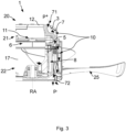
- FIG 3 an embodiment of the fan 1 in an alternative design as an axial fan is shown in a side view.
- the external rotor 20 of Figure 1 The features described are also present here, unless stated otherwise.
- the fan wheel 25 is attached to the rotor 2 with its impeller hub, completely enclosing the rotor housing 13. During operation, the fan wheel 25 generates not only the main flow but also the pressure difference ⁇ p used for the cooling air flow 7. In this embodiment, however, the outlet opening 72 is not provided on the rotor housing 13, but rather on the fan wheel 25 or the impeller hub.
- the cooling air flow 7 runs radially in the motor section 22 between the rotor housing 13 and the impeller hub 17 of the fan wheel 25, so that the cooling channel 10 in the motor section 22 is formed by the rotor housing 13 and the impeller hub of the fan wheel 25.
- FIG 4 is an embodiment of the fan 1 in a design as a radial fan, wherein the cooling channel 10, in contrast to the previous examples, is not guided along the entire rotor 2.
- the fan wheel 25 of the radial fan has the outlet opening in its impeller base disk 26 72.
- the impeller base disk 26 carries the impeller blades 9, which are curved backwards in the present embodiment.
- the cooling channel 10 therefore runs from the inflow opening 71 in the electronics housing 12 along the cooling fins 3 to the motor section 22 and therein along the stator cooling fins 5 radially outwards to the outflow opening 72 on the impeller base disk 26.
- the cooling air flow 7 is then conveyed radially outwards by the fan wheel 25.
- the cooling in the electronics section 21 is identical to the previous embodiments. In the motor section 22, cooling takes place mainly via the stator cooling fins 5.
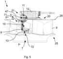
- an embodiment of the fan 1 according to the invention is shown in a design as a radial fan with the external rotor motor 20, which, as in the previous embodiments, comprises the motor section 22 and the electronic section 21 axially adjacent along the rotation axis RA with the motor electronics 11 arranged therein. All identical features described in the above embodiments are not repeated again, but also apply to the embodiment according to Figure 5 .
- the electronics section can also be aligned radially to the axis of rotation RA.
- the fan wheel 25 is mounted radially on the outside of the rotor 2.
- the fan 1 generates a pressure difference ⁇ p between its suction side and its pressure side via the fan wheel 25.
- the continuous cooling channel 10 runs from the pressure-side inlet opening 71 to the suction-side outlet opening 72 along the stator cooling fins 5, wherein during operation the cooling air flow 7 shown by arrows through the cooling channel 10 is generated exclusively passively by the pressure difference ⁇ p generated by the fan wheel 25.
- the power module 47 of the motor electronics 11 generates the most heat and is therefore arranged directly adjacent to the stator bushing having the stator cooling fins 5 in order to cool the motor section 22 and the power module 47 of the motor electronics 11 via the stator bushing.
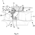
- FIG 6 A further embodiment of the fan 1 is shown, the structure being similar to that of Figure 5
- the cooling air flow 7 remains the same as in the version according to Figure 4 outside the rotor 2.
- the fan wheel 25 of the fan also has the outlet opening 72 in its impeller base plate 26, which carries the backward-curved impeller blades 9.
- the cooling channel 10 runs from the radial outside along the stator cooling fins 5 to the outlet opening 72 on the impeller base plate 26.
- the cooling air flow 7 is then conveyed radially outwards through the fan wheel 25.
- the fan 1 generates, as in the embodiment according to Figure 5 via the fan wheel 25 the pressure difference ⁇ p between its suction side and its pressure side.
- the cooling air flow 7 shown by arrows through the cooling channel 10 is generated exclusively passively by the pressure difference ⁇ p generated by the fan wheel 25.
- the power module 47 of the motor electronics 11 is also arranged directly adjacent to the stator bushing having the stator cooling fins 5 in order to cool the motor section 22 and the power module 47 of the motor electronics 11 directly via the stator bushing.
- the electronics section can be aligned or positioned radially to the rotation axis RA instead of axially.
Landscapes
- Engineering & Computer Science (AREA)
- Mechanical Engineering (AREA)
- General Engineering & Computer Science (AREA)
- Physics & Mathematics (AREA)
- Thermal Sciences (AREA)
- Power Engineering (AREA)
- Motor Or Generator Cooling System (AREA)
Claims (5)
- Ventilateur doté d'un moteur à rotor externe (20), comprenant un rotor (2) tournant autour d'un axe de rotation (RA) dans une partie de moteur (22), réalisé pour recevoir une roue de ventilateur (25) de manière confinée radialement à l'extérieur, et une électronique de moteur (11) disposée dans une partie d'électronique (21), dans lequel la partie de moteur (22) et la partie d'électronique (21) sont disposées le long de l'axe de rotation (RA) de manière axialement ou radialement adjacente l'une à l'autre, dans lequel le moteur de rotor externe (20) présente dans la partie de moteur (22) une douille de stator doté d'un paquet de stator (8) et d'enroulements de moteur ainsi que d'ailettes de refroidissement de stator (5) réparties dans la direction circonférentielle, dans lequel, en fonctionnement conforme, le ventilateur (1) génère par l'intermédiaire de la roue de ventilateur (25) une différence de pression (Δp) entre son côté aspiration et son côté refoulement, dans lequel un canal de refroidissement (10) continu s'étend à l'intérieur du moteur de rotor externe (20) d'une ouverture d'entrée côté refoulement (71) à une ouverture d'écoulement côté aspiration (72) le long des ailettes de refroidissement de stator (5),
caractérisé en ce qu'en cours de fonctionnement, un courant d'air de refroidissement (7) peut être généré à travers le canal de refroidissement (10) de manière exclusivement passive par la différence de pression (Δp) générée par la roue de ventilateur (25), dans lequel au moins un module de puissance (47) de l'électronique de moteur (11) est disposé de manière directement adjacente à la douille de stator présentant les ailettes de refroidissement de stator (5) afin de refroidir la partie de moteur (22) et au moins le module de puissance (47) de l'électronique de moteur (11) par l'intermédiaire de la douille de stator. - Ventilateur selon la revendication 1, caractérisé en ce que la roue de ventilateur (25) présente un disque de fond de roue (26) doté de pales de roue (9) réalisées sur celui-ci et dans lequel est réalisé l'ouverture d'écoulement (72).
- Ventilateur selon l'une quelconque des revendications précédentes 1 ou 2, caractérisé en ce que le moteur de rotor externe (20) présente dans la partie de moteur (22) une douille de stator dotée d'un paquet de stator (8) et d'enroulements de moteur ainsi que d'ailettes de refroidissement de stator (5) réparties dans la direction circonférentielle, et dans lequel le canal de refroidissement (10) s'étend le long des ailettes de refroidissement de stator (5) et le long du paquet de stator (8).
- Ventilateur selon l'une quelconque des revendications précédentes, caractérisé en ce que le canal de refroidissement (10) s'étend dans la partie d'électronique (21) et la partie de moteur (22) de manière localement limitée dans la direction circonférentielle.
- Ventilateur selon l'une quelconque des revendications précédentes, caractérisé en ce que le rotor (2) est associé au côté aspiration et l'électronique de moteur (11) est associé au côté refoulement.
Applications Claiming Priority (2)
| Application Number | Priority Date | Filing Date | Title |
|---|---|---|---|
| DE102020100865.1A DE102020100865A1 (de) | 2020-01-16 | 2020-01-16 | Ventilator mit einem Außenläufermotor und Kühlkanal zur Kühlung der Motorelektronik und von Motorantriebskomponenten |
| EP21151059.9A EP3851679B1 (fr) | 2020-01-16 | 2021-01-12 | Ventilateur doté d'un moteur à rotor externe et canal de refroidissement destiné au refroidissement de l'électronique de moteur et des composants de l'entraînement de moteur |
Related Parent Applications (2)
| Application Number | Title | Priority Date | Filing Date |
|---|---|---|---|
| EP21151059.9A Division-Into EP3851679B1 (fr) | 2020-01-16 | 2021-01-12 | Ventilateur doté d'un moteur à rotor externe et canal de refroidissement destiné au refroidissement de l'électronique de moteur et des composants de l'entraînement de moteur |
| EP21151059.9A Division EP3851679B1 (fr) | 2020-01-16 | 2021-01-12 | Ventilateur doté d'un moteur à rotor externe et canal de refroidissement destiné au refroidissement de l'électronique de moteur et des composants de l'entraînement de moteur |
Publications (2)
| Publication Number | Publication Date |
|---|---|
| EP4006348A1 EP4006348A1 (fr) | 2022-06-01 |
| EP4006348B1 true EP4006348B1 (fr) | 2024-08-07 |
Family
ID=74175610
Family Applications (2)
| Application Number | Title | Priority Date | Filing Date |
|---|---|---|---|
| EP22152257.6A Active EP4006348B1 (fr) | 2020-01-16 | 2021-01-12 | Ventilateur doté d'un moteur à rotor externe et canal de refroidissement destiné au refroidissement de l'électronique du moteur et des composants d'entraînement du moteur |
| EP21151059.9A Active EP3851679B1 (fr) | 2020-01-16 | 2021-01-12 | Ventilateur doté d'un moteur à rotor externe et canal de refroidissement destiné au refroidissement de l'électronique de moteur et des composants de l'entraînement de moteur |
Family Applications After (1)
| Application Number | Title | Priority Date | Filing Date |
|---|---|---|---|
| EP21151059.9A Active EP3851679B1 (fr) | 2020-01-16 | 2021-01-12 | Ventilateur doté d'un moteur à rotor externe et canal de refroidissement destiné au refroidissement de l'électronique de moteur et des composants de l'entraînement de moteur |
Country Status (4)
| Country | Link |
|---|---|
| US (1) | US11680584B2 (fr) |
| EP (2) | EP4006348B1 (fr) |
| CN (1) | CN113141089B (fr) |
| DE (1) | DE102020100865A1 (fr) |
Families Citing this family (1)
| Publication number | Priority date | Publication date | Assignee | Title |
|---|---|---|---|---|
| CN119765794B (zh) * | 2024-12-17 | 2025-08-26 | 安徽致钲电驱动技术有限公司 | 一种高效散热集成式电机 |
Citations (19)
| Publication number | Priority date | Publication date | Assignee | Title |
|---|---|---|---|---|
| US5217353A (en) | 1990-10-30 | 1993-06-08 | Industrie Magneti Marelli Spa | Fan, particularly for motor vehicles |
| EP0645542A1 (fr) * | 1993-09-24 | 1995-03-29 | Ecia - Equipements Et Composants Pour L'industrie Automobile | "Groupe motoventilateur à moyeu perfectionné" |
| US5818133A (en) | 1996-04-19 | 1998-10-06 | Siemens Canada Ltd. | Brushless motor with tubular bearing support |
| US5944497A (en) | 1997-11-25 | 1999-08-31 | Siemens Canada Limited | Fan assembly having an air directing member to cool a motor |
| US6107708A (en) | 1998-03-16 | 2000-08-22 | Asmo, Co., Ltd. | Brushless motor |
| EP1050682A2 (fr) | 1999-05-07 | 2000-11-08 | GATE S.p.A. | Motoventilateur, notamment pour l' échancheur de chaleur pour véhicule automobile |
| WO2002027895A1 (fr) | 2000-09-27 | 2002-04-04 | Zexel Valeo Climate Control Corporation | Moteur sans balais |
| US20050067500A1 (en) | 2003-09-30 | 2005-03-31 | Valeo Electrical Systems, Inc. | Fan hub assembly for effective motor cooling |
| EP1454400B1 (fr) | 2001-12-14 | 2006-05-03 | Conti Temic microelectronic GmbH | Unite d'entrainement electrique |
| WO2008061502A1 (fr) | 2006-11-24 | 2008-05-29 | Temic Automotive Electric Motors Gmbh | Ventilateur axial pour un ventilateur de véhicule |
| WO2008146154A2 (fr) | 2007-05-30 | 2008-12-04 | Spal Automotive S.R.L. | Unité de ventilation |
| DE102010046672A1 (de) | 2010-09-27 | 2012-03-29 | Valeo Klimasysteme Gmbh | Fahrzeuglüfter und Belüftungsanlage |
| DE102011053611A1 (de) | 2011-09-14 | 2013-03-14 | Ebm-Papst Mulfingen Gmbh & Co. Kg | Rotierende elektrische Maschine |
| EP1621773B1 (fr) | 2004-07-30 | 2013-04-17 | Brose Fahrzeugteile GmbH & Co. KG, Würzburg | Ventilateur de refroidissement avec moteur électrique |
| DE102013109577A1 (de) | 2012-09-05 | 2014-03-06 | Johnson Electric S.A. | Gebläsemodul für einen Wärmetauscher |
| US20140265664A1 (en) | 2013-03-15 | 2014-09-18 | Regal Beloit Australia Pty Ltd. | Air-cooled electric machine and method of assembling the same |
| US20160079824A1 (en) | 2014-09-15 | 2016-03-17 | Regal Beloit America, Inc. | Air-cooled electric machine and method of assembling the same |
| DE202016102350U1 (de) | 2016-05-03 | 2016-06-06 | Ebm-Papst Mulfingen Gmbh & Co. Kg | Motoraufnahmevorrichtung |
| DE102015105188A1 (de) | 2015-04-02 | 2016-10-06 | Ebm-Papst Mulfingen Gmbh & Co. Kg | Elektromotor mit drückender Kühlluftförderung sowie Verfahren zum Kühlen von Bauteilen des Elektromotors |
Family Cites Families (9)
| Publication number | Priority date | Publication date | Assignee | Title |
|---|---|---|---|---|
| US227895A (en) | 1880-05-25 | Chaeles a | ||
| FR2795458B1 (fr) * | 1999-06-24 | 2002-06-14 | Jeumont Ind | Motoventilateur de mise en circulation d'un fluide dans une installation d'echange thermique et procede de refroidissement du moteur d'entrainement du motoventilateur |
| CN1223306C (zh) * | 2002-05-31 | 2005-10-19 | 乐金电子(天津)电器有限公司 | 吸尘器用离心送风装置 |
| DE102010012392A1 (de) | 2010-03-22 | 2011-09-22 | Ebm-Papst Mulfingen Gmbh & Co. Kg | Ventilator |
| DE102012107109A1 (de) | 2012-08-02 | 2014-02-06 | Ebm-Papst Mulfingen Gmbh & Co. Kg | "Aktive Kühlung eines Motors mit integriertem Kühlkanal" |
| DE102014112821A1 (de) * | 2014-09-05 | 2016-03-10 | Ebm-Papst Mulfingen Gmbh & Co. Kg | Lüfter mit Leiterplattenkühlkreislauf |
| JP6707954B2 (ja) | 2016-03-31 | 2020-06-10 | 株式会社デンソー | ファンモータ |
| CN109114007B (zh) * | 2018-08-23 | 2025-01-10 | 浙江东欣节能科技有限公司 | 电动水泵 |
| DE102019101471A1 (de) * | 2019-01-22 | 2020-07-23 | Ebm-Papst Landshut Gmbh | Außenläufermotor mit Kühlrad |
-
2020
- 2020-01-16 DE DE102020100865.1A patent/DE102020100865A1/de active Pending
-
2021
- 2021-01-12 US US17/146,654 patent/US11680584B2/en active Active
- 2021-01-12 EP EP22152257.6A patent/EP4006348B1/fr active Active
- 2021-01-12 EP EP21151059.9A patent/EP3851679B1/fr active Active
- 2021-01-13 CN CN202110040237.2A patent/CN113141089B/zh active Active
Patent Citations (20)
| Publication number | Priority date | Publication date | Assignee | Title |
|---|---|---|---|---|
| US5217353A (en) | 1990-10-30 | 1993-06-08 | Industrie Magneti Marelli Spa | Fan, particularly for motor vehicles |
| EP0645542A1 (fr) * | 1993-09-24 | 1995-03-29 | Ecia - Equipements Et Composants Pour L'industrie Automobile | "Groupe motoventilateur à moyeu perfectionné" |
| US5818133A (en) | 1996-04-19 | 1998-10-06 | Siemens Canada Ltd. | Brushless motor with tubular bearing support |
| US5944497A (en) | 1997-11-25 | 1999-08-31 | Siemens Canada Limited | Fan assembly having an air directing member to cool a motor |
| US6107708A (en) | 1998-03-16 | 2000-08-22 | Asmo, Co., Ltd. | Brushless motor |
| EP1050682A2 (fr) | 1999-05-07 | 2000-11-08 | GATE S.p.A. | Motoventilateur, notamment pour l' échancheur de chaleur pour véhicule automobile |
| US6384494B1 (en) * | 1999-05-07 | 2002-05-07 | Gate S.P.A. | Motor-driven fan, particularly for a motor vehicle heat exchanger |
| WO2002027895A1 (fr) | 2000-09-27 | 2002-04-04 | Zexel Valeo Climate Control Corporation | Moteur sans balais |
| EP1454400B1 (fr) | 2001-12-14 | 2006-05-03 | Conti Temic microelectronic GmbH | Unite d'entrainement electrique |
| US20050067500A1 (en) | 2003-09-30 | 2005-03-31 | Valeo Electrical Systems, Inc. | Fan hub assembly for effective motor cooling |
| EP1621773B1 (fr) | 2004-07-30 | 2013-04-17 | Brose Fahrzeugteile GmbH & Co. KG, Würzburg | Ventilateur de refroidissement avec moteur électrique |
| WO2008061502A1 (fr) | 2006-11-24 | 2008-05-29 | Temic Automotive Electric Motors Gmbh | Ventilateur axial pour un ventilateur de véhicule |
| WO2008146154A2 (fr) | 2007-05-30 | 2008-12-04 | Spal Automotive S.R.L. | Unité de ventilation |
| DE102010046672A1 (de) | 2010-09-27 | 2012-03-29 | Valeo Klimasysteme Gmbh | Fahrzeuglüfter und Belüftungsanlage |
| DE102011053611A1 (de) | 2011-09-14 | 2013-03-14 | Ebm-Papst Mulfingen Gmbh & Co. Kg | Rotierende elektrische Maschine |
| DE102013109577A1 (de) | 2012-09-05 | 2014-03-06 | Johnson Electric S.A. | Gebläsemodul für einen Wärmetauscher |
| US20140265664A1 (en) | 2013-03-15 | 2014-09-18 | Regal Beloit Australia Pty Ltd. | Air-cooled electric machine and method of assembling the same |
| US20160079824A1 (en) | 2014-09-15 | 2016-03-17 | Regal Beloit America, Inc. | Air-cooled electric machine and method of assembling the same |
| DE102015105188A1 (de) | 2015-04-02 | 2016-10-06 | Ebm-Papst Mulfingen Gmbh & Co. Kg | Elektromotor mit drückender Kühlluftförderung sowie Verfahren zum Kühlen von Bauteilen des Elektromotors |
| DE202016102350U1 (de) | 2016-05-03 | 2016-06-06 | Ebm-Papst Mulfingen Gmbh & Co. Kg | Motoraufnahmevorrichtung |
Also Published As
| Publication number | Publication date |
|---|---|
| CN113141089B (zh) | 2024-05-31 |
| EP3851679A1 (fr) | 2021-07-21 |
| US20210222704A1 (en) | 2021-07-22 |
| EP3851679B1 (fr) | 2025-04-09 |
| EP4006348A1 (fr) | 2022-06-01 |
| CN113141089A (zh) | 2021-07-20 |
| DE102020100865A1 (de) | 2021-07-22 |
| US11680584B2 (en) | 2023-06-20 |
Similar Documents
| Publication | Publication Date | Title |
|---|---|---|
| EP2880745B1 (fr) | Refroidissement actif de moteur avec conduit de refroidissement intégré | |
| EP2691655B1 (fr) | Ventilateur diagonal | |
| EP1937978B1 (fr) | Ventilateur de radiateur pour un vehicule a moteur | |
| DE102016200081B4 (de) | Elektrische Maschine | |
| DE102008008300A1 (de) | Passiv-Lüfter | |
| WO2018108968A1 (fr) | Machine électrique | |
| DE102007055207A1 (de) | Gebläsemotor | |
| EP2880746A2 (fr) | Refroidissement actif d'un moteur | |
| EP3278427B1 (fr) | Moteur électrique présentant un apport d'air de refroidissement comprimé ainsi que procédé pour le refroidissement d'éléments du moteur électrique | |
| EP3729611B1 (fr) | Moteur de rouleau avec circuit fermé de refroidissement | |
| EP4006348B1 (fr) | Ventilateur doté d'un moteur à rotor externe et canal de refroidissement destiné au refroidissement de l'électronique du moteur et des composants d'entraînement du moteur | |
| DE102017202801A1 (de) | Rotorblechpaket für einen Rotor | |
| EP4229740A1 (fr) | Pompe centrifuge comprenant un entraînement | |
| WO2010145730A1 (fr) | Ensemble rotor pour une machine à énergie fluidique, et turbocompresseur entraîné électriquement | |
| DE102017205687B4 (de) | Rotor für eine elektrische Maschine | |
| EP3513486B1 (fr) | Moteur électrique à refroidissement amélioré pour entraîner un ventilateur | |
| EP4229741B1 (fr) | Pompe centrifuge comprenant un entraînement | |
| WO2020104130A1 (fr) | Unité de montage de rotor à fonction de refroidissement | |
| EP4206474B1 (fr) | Pompe à vide | |
| EP3907406B1 (fr) | Pompe à vide | |
| EP3161351B1 (fr) | Entraînement | |
| WO2023232660A1 (fr) | Roue de refroidissement destinée au refroidissement actif d'un stator de moteur électrique | |
| EP3804095B1 (fr) | Rotor pour une machine électrique, en particulier d'un véhicule automobile, ainsi que machine électrique, en particulier pour un véhicule automobile | |
| DE102022000354A1 (de) | Elektromotor, vorzugsweise Außenläufermotor, vorzugsweise zum Antreiben eines Turbomaschinenlaufrades, mit einem Kühllüfterrad, welches eine andere, vorteilhaft höhere Rotationsgeschwindigkeit hat als der Rotor des Motors | |
| DE102012025877B3 (de) | Aktive Kühlung eines Motors |
Legal Events
| Date | Code | Title | Description |
|---|---|---|---|
| PUAI | Public reference made under article 153(3) epc to a published international application that has entered the european phase |
Free format text: ORIGINAL CODE: 0009012 |
|
| STAA | Information on the status of an ep patent application or granted ep patent |
Free format text: STATUS: THE APPLICATION HAS BEEN PUBLISHED |
|
| AC | Divisional application: reference to earlier application |
Ref document number: 3851679 Country of ref document: EP Kind code of ref document: P |
|
| AK | Designated contracting states |
Kind code of ref document: A1 Designated state(s): AL AT BE BG CH CY CZ DE DK EE ES FI FR GB GR HR HU IE IS IT LI LT LU LV MC MK MT NL NO PL PT RO RS SE SI SK SM TR |
|
| STAA | Information on the status of an ep patent application or granted ep patent |
Free format text: STATUS: REQUEST FOR EXAMINATION WAS MADE |
|
| 17P | Request for examination filed |
Effective date: 20220930 |
|
| RBV | Designated contracting states (corrected) |
Designated state(s): AL AT BE BG CH CY CZ DE DK EE ES FI FR GB GR HR HU IE IS IT LI LT LU LV MC MK MT NL NO PL PT RO RS SE SI SK SM TR |
|
| GRAP | Despatch of communication of intention to grant a patent |
Free format text: ORIGINAL CODE: EPIDOSNIGR1 |
|
| STAA | Information on the status of an ep patent application or granted ep patent |
Free format text: STATUS: GRANT OF PATENT IS INTENDED |
|
| INTG | Intention to grant announced |
Effective date: 20240326 |
|
| P01 | Opt-out of the competence of the unified patent court (upc) registered |
Effective date: 20240523 |
|
| GRAS | Grant fee paid |
Free format text: ORIGINAL CODE: EPIDOSNIGR3 |
|
| GRAA | (expected) grant |
Free format text: ORIGINAL CODE: 0009210 |
|
| STAA | Information on the status of an ep patent application or granted ep patent |
Free format text: STATUS: THE PATENT HAS BEEN GRANTED |
|
| AC | Divisional application: reference to earlier application |
Ref document number: 3851679 Country of ref document: EP Kind code of ref document: P |
|
| AK | Designated contracting states |
Kind code of ref document: B1 Designated state(s): AL AT BE BG CH CY CZ DE DK EE ES FI FR GB GR HR HU IE IS IT LI LT LU LV MC MK MT NL NO PL PT RO RS SE SI SK SM TR |
|
| REG | Reference to a national code |
Ref country code: GB Ref legal event code: FG4D Free format text: NOT ENGLISH |
|
| REG | Reference to a national code |
Ref country code: CH Ref legal event code: EP |
|
| REG | Reference to a national code |
Ref country code: IE Ref legal event code: FG4D Free format text: LANGUAGE OF EP DOCUMENT: GERMAN |
|
| REG | Reference to a national code |
Ref country code: DE Ref legal event code: R096 Ref document number: 502021004751 Country of ref document: DE |
|
| REG | Reference to a national code |
Ref country code: LT Ref legal event code: MG9D |
|
| REG | Reference to a national code |
Ref country code: NL Ref legal event code: MP Effective date: 20240807 |
|
| PG25 | Lapsed in a contracting state [announced via postgrant information from national office to epo] |
Ref country code: NO Free format text: LAPSE BECAUSE OF FAILURE TO SUBMIT A TRANSLATION OF THE DESCRIPTION OR TO PAY THE FEE WITHIN THE PRESCRIBED TIME-LIMIT Effective date: 20241107 |
|
| PG25 | Lapsed in a contracting state [announced via postgrant information from national office to epo] |
Ref country code: GR Free format text: LAPSE BECAUSE OF FAILURE TO SUBMIT A TRANSLATION OF THE DESCRIPTION OR TO PAY THE FEE WITHIN THE PRESCRIBED TIME-LIMIT Effective date: 20241108 Ref country code: FI Free format text: LAPSE BECAUSE OF FAILURE TO SUBMIT A TRANSLATION OF THE DESCRIPTION OR TO PAY THE FEE WITHIN THE PRESCRIBED TIME-LIMIT Effective date: 20240807 Ref country code: NL Free format text: LAPSE BECAUSE OF FAILURE TO SUBMIT A TRANSLATION OF THE DESCRIPTION OR TO PAY THE FEE WITHIN THE PRESCRIBED TIME-LIMIT Effective date: 20240807 Ref country code: PT Free format text: LAPSE BECAUSE OF FAILURE TO SUBMIT A TRANSLATION OF THE DESCRIPTION OR TO PAY THE FEE WITHIN THE PRESCRIBED TIME-LIMIT Effective date: 20241209 Ref country code: PL Free format text: LAPSE BECAUSE OF FAILURE TO SUBMIT A TRANSLATION OF THE DESCRIPTION OR TO PAY THE FEE WITHIN THE PRESCRIBED TIME-LIMIT Effective date: 20240807 |
|
| PG25 | Lapsed in a contracting state [announced via postgrant information from national office to epo] |
Ref country code: BG Free format text: LAPSE BECAUSE OF FAILURE TO SUBMIT A TRANSLATION OF THE DESCRIPTION OR TO PAY THE FEE WITHIN THE PRESCRIBED TIME-LIMIT Effective date: 20240807 |
|
| PG25 | Lapsed in a contracting state [announced via postgrant information from national office to epo] |
Ref country code: LV Free format text: LAPSE BECAUSE OF FAILURE TO SUBMIT A TRANSLATION OF THE DESCRIPTION OR TO PAY THE FEE WITHIN THE PRESCRIBED TIME-LIMIT Effective date: 20240807 |
|
| PG25 | Lapsed in a contracting state [announced via postgrant information from national office to epo] |
Ref country code: IS Free format text: LAPSE BECAUSE OF FAILURE TO SUBMIT A TRANSLATION OF THE DESCRIPTION OR TO PAY THE FEE WITHIN THE PRESCRIBED TIME-LIMIT Effective date: 20241207 |
|
| PG25 | Lapsed in a contracting state [announced via postgrant information from national office to epo] |
Ref country code: HR Free format text: LAPSE BECAUSE OF FAILURE TO SUBMIT A TRANSLATION OF THE DESCRIPTION OR TO PAY THE FEE WITHIN THE PRESCRIBED TIME-LIMIT Effective date: 20240807 |
|
| PG25 | Lapsed in a contracting state [announced via postgrant information from national office to epo] |
Ref country code: RS Free format text: LAPSE BECAUSE OF FAILURE TO SUBMIT A TRANSLATION OF THE DESCRIPTION OR TO PAY THE FEE WITHIN THE PRESCRIBED TIME-LIMIT Effective date: 20241107 Ref country code: ES Free format text: LAPSE BECAUSE OF FAILURE TO SUBMIT A TRANSLATION OF THE DESCRIPTION OR TO PAY THE FEE WITHIN THE PRESCRIBED TIME-LIMIT Effective date: 20240807 |
|
| PG25 | Lapsed in a contracting state [announced via postgrant information from national office to epo] |
Ref country code: RS Free format text: LAPSE BECAUSE OF FAILURE TO SUBMIT A TRANSLATION OF THE DESCRIPTION OR TO PAY THE FEE WITHIN THE PRESCRIBED TIME-LIMIT Effective date: 20241107 Ref country code: PT Free format text: LAPSE BECAUSE OF FAILURE TO SUBMIT A TRANSLATION OF THE DESCRIPTION OR TO PAY THE FEE WITHIN THE PRESCRIBED TIME-LIMIT Effective date: 20241209 Ref country code: PL Free format text: LAPSE BECAUSE OF FAILURE TO SUBMIT A TRANSLATION OF THE DESCRIPTION OR TO PAY THE FEE WITHIN THE PRESCRIBED TIME-LIMIT Effective date: 20240807 Ref country code: NO Free format text: LAPSE BECAUSE OF FAILURE TO SUBMIT A TRANSLATION OF THE DESCRIPTION OR TO PAY THE FEE WITHIN THE PRESCRIBED TIME-LIMIT Effective date: 20241107 Ref country code: NL Free format text: LAPSE BECAUSE OF FAILURE TO SUBMIT A TRANSLATION OF THE DESCRIPTION OR TO PAY THE FEE WITHIN THE PRESCRIBED TIME-LIMIT Effective date: 20240807 Ref country code: LV Free format text: LAPSE BECAUSE OF FAILURE TO SUBMIT A TRANSLATION OF THE DESCRIPTION OR TO PAY THE FEE WITHIN THE PRESCRIBED TIME-LIMIT Effective date: 20240807 Ref country code: IS Free format text: LAPSE BECAUSE OF FAILURE TO SUBMIT A TRANSLATION OF THE DESCRIPTION OR TO PAY THE FEE WITHIN THE PRESCRIBED TIME-LIMIT Effective date: 20241207 Ref country code: HR Free format text: LAPSE BECAUSE OF FAILURE TO SUBMIT A TRANSLATION OF THE DESCRIPTION OR TO PAY THE FEE WITHIN THE PRESCRIBED TIME-LIMIT Effective date: 20240807 Ref country code: GR Free format text: LAPSE BECAUSE OF FAILURE TO SUBMIT A TRANSLATION OF THE DESCRIPTION OR TO PAY THE FEE WITHIN THE PRESCRIBED TIME-LIMIT Effective date: 20241108 Ref country code: FI Free format text: LAPSE BECAUSE OF FAILURE TO SUBMIT A TRANSLATION OF THE DESCRIPTION OR TO PAY THE FEE WITHIN THE PRESCRIBED TIME-LIMIT Effective date: 20240807 Ref country code: ES Free format text: LAPSE BECAUSE OF FAILURE TO SUBMIT A TRANSLATION OF THE DESCRIPTION OR TO PAY THE FEE WITHIN THE PRESCRIBED TIME-LIMIT Effective date: 20240807 Ref country code: BG Free format text: LAPSE BECAUSE OF FAILURE TO SUBMIT A TRANSLATION OF THE DESCRIPTION OR TO PAY THE FEE WITHIN THE PRESCRIBED TIME-LIMIT Effective date: 20240807 |
|
| PG25 | Lapsed in a contracting state [announced via postgrant information from national office to epo] |
Ref country code: SM Free format text: LAPSE BECAUSE OF FAILURE TO SUBMIT A TRANSLATION OF THE DESCRIPTION OR TO PAY THE FEE WITHIN THE PRESCRIBED TIME-LIMIT Effective date: 20240807 Ref country code: DK Free format text: LAPSE BECAUSE OF FAILURE TO SUBMIT A TRANSLATION OF THE DESCRIPTION OR TO PAY THE FEE WITHIN THE PRESCRIBED TIME-LIMIT Effective date: 20240807 |
|
| PG25 | Lapsed in a contracting state [announced via postgrant information from national office to epo] |
Ref country code: EE Free format text: LAPSE BECAUSE OF FAILURE TO SUBMIT A TRANSLATION OF THE DESCRIPTION OR TO PAY THE FEE WITHIN THE PRESCRIBED TIME-LIMIT Effective date: 20240807 |
|
| PG25 | Lapsed in a contracting state [announced via postgrant information from national office to epo] |
Ref country code: CZ Free format text: LAPSE BECAUSE OF FAILURE TO SUBMIT A TRANSLATION OF THE DESCRIPTION OR TO PAY THE FEE WITHIN THE PRESCRIBED TIME-LIMIT Effective date: 20240807 |
|
| PG25 | Lapsed in a contracting state [announced via postgrant information from national office to epo] |
Ref country code: SK Free format text: LAPSE BECAUSE OF FAILURE TO SUBMIT A TRANSLATION OF THE DESCRIPTION OR TO PAY THE FEE WITHIN THE PRESCRIBED TIME-LIMIT Effective date: 20240807 |
|
| REG | Reference to a national code |
Ref country code: DE Ref legal event code: R026 Ref document number: 502021004751 Country of ref document: DE |
|
| PLBI | Opposition filed |
Free format text: ORIGINAL CODE: 0009260 |
|
| PLAB | Opposition data, opponent's data or that of the opponent's representative modified |
Free format text: ORIGINAL CODE: 0009299OPPO |
|
| PLAX | Notice of opposition and request to file observation + time limit sent |
Free format text: ORIGINAL CODE: EPIDOSNOBS2 |
|
| 26 | Opposition filed |
Opponent name: ZIEHL-ABEGG SE Effective date: 20250507 |
|
| R26 | Opposition filed (corrected) |
Opponent name: ZIEHL-ABEGG SE Effective date: 20250507 |
|
| REG | Reference to a national code |
Ref country code: CH Ref legal event code: PL |
|
| PLBB | Reply of patent proprietor to notice(s) of opposition received |
Free format text: ORIGINAL CODE: EPIDOSNOBS3 |
|
| PG25 | Lapsed in a contracting state [announced via postgrant information from national office to epo] |
Ref country code: SE Free format text: LAPSE BECAUSE OF FAILURE TO SUBMIT A TRANSLATION OF THE DESCRIPTION OR TO PAY THE FEE WITHIN THE PRESCRIBED TIME-LIMIT Effective date: 20240807 |
|
| PG25 | Lapsed in a contracting state [announced via postgrant information from national office to epo] |
Ref country code: MC Free format text: LAPSE BECAUSE OF FAILURE TO SUBMIT A TRANSLATION OF THE DESCRIPTION OR TO PAY THE FEE WITHIN THE PRESCRIBED TIME-LIMIT Effective date: 20240807 Ref country code: LU Free format text: LAPSE BECAUSE OF NON-PAYMENT OF DUE FEES Effective date: 20250112 |
|
| PG25 | Lapsed in a contracting state [announced via postgrant information from national office to epo] |
Ref country code: BE Free format text: LAPSE BECAUSE OF NON-PAYMENT OF DUE FEES Effective date: 20250131 |
|
| PG25 | Lapsed in a contracting state [announced via postgrant information from national office to epo] |
Ref country code: CH Free format text: LAPSE BECAUSE OF NON-PAYMENT OF DUE FEES Effective date: 20250131 |
|
| REG | Reference to a national code |
Ref country code: BE Ref legal event code: MM Effective date: 20250131 |
|
| PG25 | Lapsed in a contracting state [announced via postgrant information from national office to epo] |
Ref country code: IT Free format text: LAPSE BECAUSE OF NON-PAYMENT OF DUE FEES Effective date: 20250112 |
|
| PG25 | Lapsed in a contracting state [announced via postgrant information from national office to epo] |
Ref country code: IE Free format text: LAPSE BECAUSE OF NON-PAYMENT OF DUE FEES Effective date: 20250112 |
|
| PGFP | Annual fee paid to national office [announced via postgrant information from national office to epo] |
Ref country code: GB Payment date: 20260122 Year of fee payment: 6 |
|
| PGFP | Annual fee paid to national office [announced via postgrant information from national office to epo] |
Ref country code: DE Payment date: 20260120 Year of fee payment: 6 |
|
| PGFP | Annual fee paid to national office [announced via postgrant information from national office to epo] |
Ref country code: AT Payment date: 20260119 Year of fee payment: 6 |
|
| PG25 | Lapsed in a contracting state [announced via postgrant information from national office to epo] |
Ref country code: RO Free format text: LAPSE BECAUSE OF FAILURE TO SUBMIT A TRANSLATION OF THE DESCRIPTION OR TO PAY THE FEE WITHIN THE PRESCRIBED TIME-LIMIT Effective date: 20240807 Ref country code: IT Free format text: LAPSE BECAUSE OF NON-PAYMENT OF DUE FEES Effective date: 20250112 |
|
| PGFP | Annual fee paid to national office [announced via postgrant information from national office to epo] |
Ref country code: IT Payment date: 20260130 Year of fee payment: 6 |
|
| PGRI | Patent reinstated in contracting state [announced from national office to epo] |
Ref country code: IT Effective date: 20250603 |
|
| PGFP | Annual fee paid to national office [announced via postgrant information from national office to epo] |
Ref country code: FR Payment date: 20260128 Year of fee payment: 6 |