EP4006376A1 - Gasbecher für eine dämpferanordnung und dämpferanordnung - Google Patents
Gasbecher für eine dämpferanordnung und dämpferanordnung Download PDFInfo
- Publication number
- EP4006376A1 EP4006376A1 EP21208906.4A EP21208906A EP4006376A1 EP 4006376 A1 EP4006376 A1 EP 4006376A1 EP 21208906 A EP21208906 A EP 21208906A EP 4006376 A1 EP4006376 A1 EP 4006376A1
- Authority
- EP
- European Patent Office
- Prior art keywords
- decoupler
- gas cup
- bridging member
- stopper
- gas
- Prior art date
- Legal status (The legal status is an assumption and is not a legal conclusion. Google has not performed a legal analysis and makes no representation as to the accuracy of the status listed.)
- Granted
Links
Images



Classifications
-
- F—MECHANICAL ENGINEERING; LIGHTING; HEATING; WEAPONS; BLASTING
- F16—ENGINEERING ELEMENTS AND UNITS; GENERAL MEASURES FOR PRODUCING AND MAINTAINING EFFECTIVE FUNCTIONING OF MACHINES OR INSTALLATIONS; THERMAL INSULATION IN GENERAL
- F16F—SPRINGS; SHOCK-ABSORBERS; MEANS FOR DAMPING VIBRATION
- F16F9/00—Springs, vibration-dampers, shock-absorbers, or similarly-constructed movement-dampers using a fluid or the equivalent as damping medium
- F16F9/06—Springs, vibration-dampers, shock-absorbers, or similarly-constructed movement-dampers using a fluid or the equivalent as damping medium using both gas and liquid
- F16F9/08—Springs, vibration-dampers, shock-absorbers, or similarly-constructed movement-dampers using a fluid or the equivalent as damping medium using both gas and liquid where gas is in a chamber with a flexible wall
- F16F9/088—Springs, vibration-dampers, shock-absorbers, or similarly-constructed movement-dampers using a fluid or the equivalent as damping medium using both gas and liquid where gas is in a chamber with a flexible wall comprising a gas spring with a flexible wall provided within the cylinder on the piston rod of a monotubular damper or within the inner tube of a bitubular damper
-
- F—MECHANICAL ENGINEERING; LIGHTING; HEATING; WEAPONS; BLASTING
- F16—ENGINEERING ELEMENTS AND UNITS; GENERAL MEASURES FOR PRODUCING AND MAINTAINING EFFECTIVE FUNCTIONING OF MACHINES OR INSTALLATIONS; THERMAL INSULATION IN GENERAL
- F16F—SPRINGS; SHOCK-ABSORBERS; MEANS FOR DAMPING VIBRATION
- F16F9/00—Springs, vibration-dampers, shock-absorbers, or similarly-constructed movement-dampers using a fluid or the equivalent as damping medium
- F16F9/06—Springs, vibration-dampers, shock-absorbers, or similarly-constructed movement-dampers using a fluid or the equivalent as damping medium using both gas and liquid
- F16F9/066—Units characterised by the partition, baffle or like element
- F16F9/067—Partitions of the piston type, e.g. sliding pistons
-
- B—PERFORMING OPERATIONS; TRANSPORTING
- B60—VEHICLES IN GENERAL
- B60G—VEHICLE SUSPENSION ARRANGEMENTS
- B60G13/00—Resilient suspensions characterised by arrangement, location or type of vibration dampers
- B60G13/02—Resilient suspensions characterised by arrangement, location or type of vibration dampers having dampers dissipating energy, e.g. frictionally
- B60G13/06—Resilient suspensions characterised by arrangement, location or type of vibration dampers having dampers dissipating energy, e.g. frictionally of fluid type
- B60G13/08—Resilient suspensions characterised by arrangement, location or type of vibration dampers having dampers dissipating energy, e.g. frictionally of fluid type hydraulic
-
- F—MECHANICAL ENGINEERING; LIGHTING; HEATING; WEAPONS; BLASTING
- F16—ENGINEERING ELEMENTS AND UNITS; GENERAL MEASURES FOR PRODUCING AND MAINTAINING EFFECTIVE FUNCTIONING OF MACHINES OR INSTALLATIONS; THERMAL INSULATION IN GENERAL
- F16F—SPRINGS; SHOCK-ABSORBERS; MEANS FOR DAMPING VIBRATION
- F16F9/00—Springs, vibration-dampers, shock-absorbers, or similarly-constructed movement-dampers using a fluid or the equivalent as damping medium
- F16F9/06—Springs, vibration-dampers, shock-absorbers, or similarly-constructed movement-dampers using a fluid or the equivalent as damping medium using both gas and liquid
- F16F9/061—Mono-tubular units
-
- F—MECHANICAL ENGINEERING; LIGHTING; HEATING; WEAPONS; BLASTING
- F16—ENGINEERING ELEMENTS AND UNITS; GENERAL MEASURES FOR PRODUCING AND MAINTAINING EFFECTIVE FUNCTIONING OF MACHINES OR INSTALLATIONS; THERMAL INSULATION IN GENERAL
- F16F—SPRINGS; SHOCK-ABSORBERS; MEANS FOR DAMPING VIBRATION
- F16F9/00—Springs, vibration-dampers, shock-absorbers, or similarly-constructed movement-dampers using a fluid or the equivalent as damping medium
- F16F9/06—Springs, vibration-dampers, shock-absorbers, or similarly-constructed movement-dampers using a fluid or the equivalent as damping medium using both gas and liquid
- F16F9/064—Units characterised by the location or shape of the expansion chamber
-
- F—MECHANICAL ENGINEERING; LIGHTING; HEATING; WEAPONS; BLASTING
- F16—ENGINEERING ELEMENTS AND UNITS; GENERAL MEASURES FOR PRODUCING AND MAINTAINING EFFECTIVE FUNCTIONING OF MACHINES OR INSTALLATIONS; THERMAL INSULATION IN GENERAL
- F16F—SPRINGS; SHOCK-ABSORBERS; MEANS FOR DAMPING VIBRATION
- F16F9/00—Springs, vibration-dampers, shock-absorbers, or similarly-constructed movement-dampers using a fluid or the equivalent as damping medium
- F16F9/06—Springs, vibration-dampers, shock-absorbers, or similarly-constructed movement-dampers using a fluid or the equivalent as damping medium using both gas and liquid
- F16F9/066—Units characterised by the partition, baffle or like element
-
- F—MECHANICAL ENGINEERING; LIGHTING; HEATING; WEAPONS; BLASTING
- F16—ENGINEERING ELEMENTS AND UNITS; GENERAL MEASURES FOR PRODUCING AND MAINTAINING EFFECTIVE FUNCTIONING OF MACHINES OR INSTALLATIONS; THERMAL INSULATION IN GENERAL
- F16F—SPRINGS; SHOCK-ABSORBERS; MEANS FOR DAMPING VIBRATION
- F16F9/00—Springs, vibration-dampers, shock-absorbers, or similarly-constructed movement-dampers using a fluid or the equivalent as damping medium
- F16F9/32—Details
- F16F9/3207—Constructional features
-
- F—MECHANICAL ENGINEERING; LIGHTING; HEATING; WEAPONS; BLASTING
- F16—ENGINEERING ELEMENTS AND UNITS; GENERAL MEASURES FOR PRODUCING AND MAINTAINING EFFECTIVE FUNCTIONING OF MACHINES OR INSTALLATIONS; THERMAL INSULATION IN GENERAL
- F16F—SPRINGS; SHOCK-ABSORBERS; MEANS FOR DAMPING VIBRATION
- F16F9/00—Springs, vibration-dampers, shock-absorbers, or similarly-constructed movement-dampers using a fluid or the equivalent as damping medium
- F16F9/32—Details
- F16F9/48—Arrangements for providing different damping effects at different parts of the stroke
-
- F—MECHANICAL ENGINEERING; LIGHTING; HEATING; WEAPONS; BLASTING
- F16—ENGINEERING ELEMENTS AND UNITS; GENERAL MEASURES FOR PRODUCING AND MAINTAINING EFFECTIVE FUNCTIONING OF MACHINES OR INSTALLATIONS; THERMAL INSULATION IN GENERAL
- F16F—SPRINGS; SHOCK-ABSORBERS; MEANS FOR DAMPING VIBRATION
- F16F9/00—Springs, vibration-dampers, shock-absorbers, or similarly-constructed movement-dampers using a fluid or the equivalent as damping medium
- F16F9/32—Details
- F16F9/50—Special means providing automatic damping adjustment, i.e. self-adjustment of damping by particular sliding movements of a valve element, other than flexions or displacement of valve discs; Special means providing self-adjustment of spring characteristics
- F16F9/512—Means responsive to load action, i.e. static load on the damper or dynamic fluid pressure changes in the damper, e.g. due to changes in velocity
- F16F9/5123—Means responsive to load action, i.e. static load on the damper or dynamic fluid pressure changes in the damper, e.g. due to changes in velocity responsive to the static or steady-state load on the damper
-
- B—PERFORMING OPERATIONS; TRANSPORTING
- B60—VEHICLES IN GENERAL
- B60G—VEHICLE SUSPENSION ARRANGEMENTS
- B60G17/00—Resilient suspensions having means for adjusting the spring or vibration-damper characteristics, for regulating the distance between a supporting surface and a sprung part of vehicle or for locking suspension during use to meet varying vehicular or surface conditions, e.g. due to speed or load
- B60G17/06—Characteristics of dampers, e.g. mechanical dampers
- B60G17/08—Characteristics of fluid dampers
-
- B—PERFORMING OPERATIONS; TRANSPORTING
- B60—VEHICLES IN GENERAL
- B60G—VEHICLE SUSPENSION ARRANGEMENTS
- B60G2202/00—Indexing codes relating to the type of spring, damper or actuator
- B60G2202/20—Type of damper
- B60G2202/24—Fluid damper
-
- B—PERFORMING OPERATIONS; TRANSPORTING
- B60—VEHICLES IN GENERAL
- B60G—VEHICLE SUSPENSION ARRANGEMENTS
- B60G2204/00—Indexing codes related to suspensions per se or to auxiliary parts
- B60G2204/62—Adjustable continuously, e.g. during driving
-
- B—PERFORMING OPERATIONS; TRANSPORTING
- B60—VEHICLES IN GENERAL
- B60G—VEHICLE SUSPENSION ARRANGEMENTS
- B60G2206/00—Indexing codes related to the manufacturing of suspensions: constructional features, the materials used, procedures or tools
- B60G2206/01—Constructional features of suspension elements, e.g. arms, dampers, springs
- B60G2206/40—Constructional features of dampers and/or springs
- B60G2206/41—Dampers
-
- B—PERFORMING OPERATIONS; TRANSPORTING
- B60—VEHICLES IN GENERAL
- B60G—VEHICLE SUSPENSION ARRANGEMENTS
- B60G2206/00—Indexing codes related to the manufacturing of suspensions: constructional features, the materials used, procedures or tools
- B60G2206/01—Constructional features of suspension elements, e.g. arms, dampers, springs
- B60G2206/70—Materials used in suspensions
- B60G2206/71—Light weight materials
- B60G2206/7102—Aluminium alloys
-
- B—PERFORMING OPERATIONS; TRANSPORTING
- B60—VEHICLES IN GENERAL
- B60G—VEHICLE SUSPENSION ARRANGEMENTS
- B60G2206/00—Indexing codes related to the manufacturing of suspensions: constructional features, the materials used, procedures or tools
- B60G2206/01—Constructional features of suspension elements, e.g. arms, dampers, springs
- B60G2206/70—Materials used in suspensions
- B60G2206/73—Rubber; Elastomers
-
- B—PERFORMING OPERATIONS; TRANSPORTING
- B60—VEHICLES IN GENERAL
- B60G—VEHICLE SUSPENSION ARRANGEMENTS
- B60G2500/00—Indexing codes relating to the regulated action or device
- B60G2500/10—Damping action or damper
-
- B—PERFORMING OPERATIONS; TRANSPORTING
- B60—VEHICLES IN GENERAL
- B60G—VEHICLE SUSPENSION ARRANGEMENTS
- B60G2600/00—Indexing codes relating to particular elements, systems or processes used on suspension systems or suspension control systems
- B60G2600/21—Self-controlled or adjusted
-
- B—PERFORMING OPERATIONS; TRANSPORTING
- B60—VEHICLES IN GENERAL
- B60G—VEHICLE SUSPENSION ARRANGEMENTS
- B60G2800/00—Indexing codes relating to the type of movement or to the condition of the vehicle and to the end result to be achieved by the control action
- B60G2800/16—Running
- B60G2800/162—Reducing road induced vibrations
-
- F—MECHANICAL ENGINEERING; LIGHTING; HEATING; WEAPONS; BLASTING
- F16—ENGINEERING ELEMENTS AND UNITS; GENERAL MEASURES FOR PRODUCING AND MAINTAINING EFFECTIVE FUNCTIONING OF MACHINES OR INSTALLATIONS; THERMAL INSULATION IN GENERAL
- F16F—SPRINGS; SHOCK-ABSORBERS; MEANS FOR DAMPING VIBRATION
- F16F2222/00—Special physical effects, e.g. nature of damping effects
- F16F2222/12—Fluid damping
-
- F—MECHANICAL ENGINEERING; LIGHTING; HEATING; WEAPONS; BLASTING
- F16—ENGINEERING ELEMENTS AND UNITS; GENERAL MEASURES FOR PRODUCING AND MAINTAINING EFFECTIVE FUNCTIONING OF MACHINES OR INSTALLATIONS; THERMAL INSULATION IN GENERAL
- F16F—SPRINGS; SHOCK-ABSORBERS; MEANS FOR DAMPING VIBRATION
- F16F2224/00—Materials; Material properties
- F16F2224/02—Materials; Material properties solids
- F16F2224/0208—Alloys
-
- F—MECHANICAL ENGINEERING; LIGHTING; HEATING; WEAPONS; BLASTING
- F16—ENGINEERING ELEMENTS AND UNITS; GENERAL MEASURES FOR PRODUCING AND MAINTAINING EFFECTIVE FUNCTIONING OF MACHINES OR INSTALLATIONS; THERMAL INSULATION IN GENERAL
- F16F—SPRINGS; SHOCK-ABSORBERS; MEANS FOR DAMPING VIBRATION
- F16F2224/00—Materials; Material properties
- F16F2224/02—Materials; Material properties solids
- F16F2224/025—Elastomers
-
- F—MECHANICAL ENGINEERING; LIGHTING; HEATING; WEAPONS; BLASTING
- F16—ENGINEERING ELEMENTS AND UNITS; GENERAL MEASURES FOR PRODUCING AND MAINTAINING EFFECTIVE FUNCTIONING OF MACHINES OR INSTALLATIONS; THERMAL INSULATION IN GENERAL
- F16F—SPRINGS; SHOCK-ABSORBERS; MEANS FOR DAMPING VIBRATION
- F16F2228/00—Functional characteristics, e.g. variability, frequency-dependence
- F16F2228/06—Stiffness
- F16F2228/066—Variable stiffness
-
- F—MECHANICAL ENGINEERING; LIGHTING; HEATING; WEAPONS; BLASTING
- F16—ENGINEERING ELEMENTS AND UNITS; GENERAL MEASURES FOR PRODUCING AND MAINTAINING EFFECTIVE FUNCTIONING OF MACHINES OR INSTALLATIONS; THERMAL INSULATION IN GENERAL
- F16F—SPRINGS; SHOCK-ABSORBERS; MEANS FOR DAMPING VIBRATION
- F16F2230/00—Purpose; Design features
- F16F2230/0052—Physically guiding or influencing
- F16F2230/007—Physically guiding or influencing with, or used as an end stop or buffer; Limiting excessive axial separation
-
- F—MECHANICAL ENGINEERING; LIGHTING; HEATING; WEAPONS; BLASTING
- F16—ENGINEERING ELEMENTS AND UNITS; GENERAL MEASURES FOR PRODUCING AND MAINTAINING EFFECTIVE FUNCTIONING OF MACHINES OR INSTALLATIONS; THERMAL INSULATION IN GENERAL
- F16F—SPRINGS; SHOCK-ABSORBERS; MEANS FOR DAMPING VIBRATION
- F16F2232/00—Nature of movement
- F16F2232/08—Linear
-
- F—MECHANICAL ENGINEERING; LIGHTING; HEATING; WEAPONS; BLASTING
- F16—ENGINEERING ELEMENTS AND UNITS; GENERAL MEASURES FOR PRODUCING AND MAINTAINING EFFECTIVE FUNCTIONING OF MACHINES OR INSTALLATIONS; THERMAL INSULATION IN GENERAL
- F16F—SPRINGS; SHOCK-ABSORBERS; MEANS FOR DAMPING VIBRATION
- F16F2234/00—Shape
- F16F2234/02—Shape cylindrical
-
- F—MECHANICAL ENGINEERING; LIGHTING; HEATING; WEAPONS; BLASTING
- F16—ENGINEERING ELEMENTS AND UNITS; GENERAL MEASURES FOR PRODUCING AND MAINTAINING EFFECTIVE FUNCTIONING OF MACHINES OR INSTALLATIONS; THERMAL INSULATION IN GENERAL
- F16F—SPRINGS; SHOCK-ABSORBERS; MEANS FOR DAMPING VIBRATION
- F16F9/00—Springs, vibration-dampers, shock-absorbers, or similarly-constructed movement-dampers using a fluid or the equivalent as damping medium
- F16F9/06—Springs, vibration-dampers, shock-absorbers, or similarly-constructed movement-dampers using a fluid or the equivalent as damping medium using both gas and liquid
- F16F9/08—Springs, vibration-dampers, shock-absorbers, or similarly-constructed movement-dampers using a fluid or the equivalent as damping medium using both gas and liquid where gas is in a chamber with a flexible wall
Definitions
- the present invention relates generally to a gas cup for a damper assembly and a damper assembly.
- Conventional piston dampers include dampers having a tube, a piston assembly (such as a piston assembly including a piston core and a piston ring positioned outward of the piston core to define a through passageway between the piston core and the piston ring), and a piston rod.
- the tube contains a damping fluid.
- the piston assembly slidably engages the tube between the closed and open end portions of the tube.
- the piston rod has a first end portion attached to the piston assembly and a second end portion extending outside the open end portion of the tube.
- a rod guide assembly is attached to the open end portion of the tube to guide the piston rod and to seal the damping fluid within the tube.
- a floating, hermetically-sealing gas cup (such as one made of impermeable aluminum) slidingly engages the tube to separate the damping fluid from a gas and slides (floats) to adjust for the volume change caused by the moving piston rod, thermal expansion of the damping fluid, and normal loss of damping fluid, as is known to those skilled in the art.
- the gas cup has a single seal disposed in fully-circumferential surface groove on the outwardly-facing circumferential surface of the gas cup.
- the gas cup assembly includes a body having an upper surface, a lower surface, an exterior surface and an interior surface.
- the body defines an aperture extending through the upper surface and the lower surface of the body.
- a decoupler made entirely from an elastomeric material, is located in the aperture and secured to the interior surface of the body.
- these designs tend to have durability issues caused by long-term gas leakage through large elastomeric area of the decoupler and gas permeability characteristics of the elastomeric material.
- the present invention in its broadest aspect provides a gas cup which significantly reduces gas pressure loss over time.
- the present invention also provides a gas cup having variable tuning parameters, which improves the damping characteristics of a damper assembly and thereby improving the ride comfort of a user.
- the present invention also a gas cup including a decoupler having improved durability thereby increasing the operational life of the damper assembly.
- the present invention provides a damper assembly including the gas cup that improves ride comfort of a user, especially at high frequency inputs and small amplitude.
- the gas cup comprises a body including an upper surface, a lower surface, an exterior surface and an interior surface.
- the body defines an aperture extending through the upper surface and the lower surface.
- a decoupler is located in the aperture and secured to the body.
- a bridging member is located between the decoupler and the body and coupled to the decoupler and the body. The decoupler and the bridging member are made from materials having different elasticity to allow the decoupler to move in the aperture in response to a volumetric change in the damper assembly and to provide variable tuning of the damper assembly.
- the damper assembly comprises a housing extending along a center axis between an opened end and a closed end defining a space extending therebetween.
- a piston is slidably disposed in the space dividing the space into a compression chamber and a rebound chamber.
- a piston rod guide is located in the rebound chamber in sealing engagement with the opened end.
- a piston rod extends into the rebound chamber and is coupled to the piston for moving the piston in the space between a compression stroke and a rebound stroke.
- a gas cup includes a body slidably located in the compression chamber dividing the compression chamber into a gas compartment and a fluid compartment. The body includes an upper surface, a lower surface, an exterior surface and an interior surface.
- the body defines an aperture extending through the upper surface and the lower surface to allow fluid communication between the gas compartment and the fluid compartment.
- a decoupler is located in the aperture and secured to the body.
- a bridging member is located between the decoupler and the body and is coupled to the decoupler and the body. The decoupler and the bridging member are made from materials having different elasticity to allow the decoupler to move in the aperture in response to a volumetric change in the damper assembly and to provide variable tuning of the damper assembly.
- a damper assembly 20 for use in a vehicle constructed in accordance with one embodiment of the present invention is generally shown in Figure 1 .
- Figure 1 illustrates a fragment of an exemplary vehicle suspension including the damper assembly 20 being attached to a vehicle chassis 22 via a top mount 24 and a number of screws 26 disposed on a periphery of an upper surface of the top mount 24.
- the top mount 24 connects to a coil spring 28.
- the damper assembly 20 connects to the steering knuckle 30 supporting vehicle wheel 32.
- the damper assembly 20 comprises a housing 34, having a generally cylindrical shape, disposed on a center axis A and extending between an opened end 42 and a closed end 44.
- the housing 34 defines a space 36, 38, 40 extending along the center axis A between the opened end 42 and the closed end 44 for containing a working fluid.
- a mounting ring 46 having a generally circular shape, couples to the closed end 44 for securing the housing 34 to the vehicle.
- a piston 48 having a generally cylindrical shape, slidably disposed in the space 36, 38, 40 dividing the space 36, 38, 40 into a compression chamber 36, 38 and a rebound chamber 40.
- the compression chamber 36, 38 extends between the closed end 44 and the piston 48.
- the rebound chamber 40 extends between the opened end 42 and the piston 48.
- a gas cup 50 includes a body 52, having a generally cylindrical shape, slidably located in the compression chamber 36, 38 and spaced apart from the piston 48.
- the gas cup 50 divides the compression chamber 36, 38 into a gas compartment 36 and a fluid compartment 38.
- the gas compartment 36 extends between the closed end 44 and the gas cup 50 for containing a gas.
- the gas can be pressurized in the gas compartment.
- the fluid compartment 38 extends between the gas cup 50 and the piston 48 for containing the working fluid.
- the gas cup 50 separates the working fluid and the pressurized gas to compensate for the volumetric change in the fluid compartment 38 and the rebound chamber 40 to absorb pressure pulse, damp hydraulic impact, and store energy to provide a damping force.
- the applications can be included in passive shock absorber, semi-active suspension systems, active suspension systems, hydraulic pump, actuator, and accumulator which operates with fluids such as oil and water.
- the body 52 defines an aperture 54 extending along the center axis A and through the body 52 to allow fluid communication between the gas compartment 36 and the fluid compartment 38.
- the body 52 includes an upper surface 56, a lower surface 58, an exterior surface 60, and an interior surface 62.
- the upper surface 56 faces the piston 48.
- the lower surface 58 faces the closed end 44.
- the exterior surface 60 extends between the upper surface 56 and the lower surface 58 and annularly about the center axis A facing the housing 34.
- the interior surface 62 is radially spaced from the exterior surface 60 extending between the upper surface 56 and the lower surface 58 and annularly about the center axis A to define the aperture 54.
- the exterior surface 60 defines a pair of grooves 64, 66 including an upper groove 64 and a lower groove 66.
- the upper groove 64 and the lower groove 66 are axially spaced apart from one another extending annularly about the body 52.
- the upper groove 64 is located adjacent to the upper surface 56.
- the lower groove 66 is located adjacent to the lower surface 58.
- a guiding ring 67 is located in the upper groove 64 extending about the center axis A for engaging the housing 34.
- a seal ring 68 is located in the lower groove 66 extending about the center axis A and in an abutment relationship with the housing 34 for preventing gas in the gas compartment for leaking between the exterior surface 60 of the body 52 and the housing 34.
- a decoupler 70 having a generally circular shape, is located in the aperture 54 and secured to the interior surface 62 of the body 52 to separate the gas compartment 36 from the fluid compartment 38 for compensating volumetric fluid change in the fluid compartment 38 and the rebound chamber 40.
- At least one stopper 72, 74 is located in the aperture 54 coupled to the interior surface 62 for restricting movement of the decoupler 70.
- the at least one stopper 72, 74 includes an upper stopper 72 and a lower stopper 74.
- the upper stopper 72 is located adjacent to the upper surface 56 coupled to the interior surface 62 of the body 52 for restricting an axial movement of the decoupler 70 toward the upper surface 56.
- the lower stopper 74 is located adjacent to the lower surface 58 coupled to the interior surface 62 of the body 52 for restricting an axial movement of the decoupler toward the lower surface 58.
- the damper assembly 20 includes a piston rod guide 76 is located in the rebound chamber 40 and adjacent to the opened end 42 of the housing 34.
- the piston rod guide 76 is in sealing engagement with the opened end 42 of the housing 34 to close the space 36, 38, 40.
- the piston rod guide 76 defines a bore 78, having a generally cylindrical shape, extending along the center axis A and in communication with the rebound chamber 40.
- a piston rod 80 having a generally cylindrical shape, extends along the center axis A, through the bore 78, and into the rebound chamber 40 to a distal end 82.
- the piston rod 80 couples to the piston 48 for moving the piston 48 in the space 36, 38, 40 between a compression stroke and a rebound stroke.
- the compression stroke is defined as the piston rod 80 and the piston 48 move towards the closed end 44.
- the rebound stroke is defined as the piston rod 80 and the piston 48 move toward the opened end 42.
- a projection 84 extends outwardly from the distal end 82 of the piston rod 80 and through the piston 48 to a terminal end 86, spaced part from the piston 48, to couple the piston 48 to the piston rod 80.
- the piston 48 defines a hole 88, having a generally cylindrical shape, extending along the center axis A and receiving the projection 84 to allow the projection 84 to extend through the piston 48.
- a retaining member 90 is disposed at the terminal end 86 coupled to the projection 84 to secure the piston 48 to the piston rod 80.
- the piston 48 has a compression surface 92 and a rebound surface 94.
- the compression surface 92 is located in the compression chamber 36, 38 facing the closed end 44.
- the rebound surface 94 is located in the rebound chamber 40 facing the opened end 42.
- the piston 48 defines a plurality of channels 96, 98 for allowing the working fluid to flow through the piston 48 during the compression stroke and the rebound stroke.
- the plurality of channels 96, 98 includes a set of compression channels 96 and a set of rebound channels 98 extending through the piston 48 for allowing the working fluid to flow through the piston 48 during the compression stroke and the rebound stroke.
- the set of compression channels 96 located adjacent to an outer surface 100 of the piston 48, is disposed about the center axis A and circumferentially spaced from one another.
- the compression channels 96 extend from the compression surface 92 to the rebound surface 94 in a parallel relationship with the center axis A.
- the set of rebound channels 98, radially spaced apart from the set of compression channels 96 extends from the compression surface 92 to the rebound surface 94 parallel to the center axis A.
- a compression valve 102 includes a plurality of discs, each having a generally circular shape, disposed on the rebound surface 94 of the piston 48 covering the set of compression channels 96 for limiting working fluid flow through the piston 48 during the compression stroke to provide a damping force during the compression stroke.
- a rebound valve 104 includes a plurality of discs, each having a generally circular shape, disposed on the compression surface 92 covering the rebound channels 98 for limiting working fluid flow through the piston 48 during the rebound stroke to provide a damping force during the rebound stroke.
- a bridging member 106 is located between the decoupler 70 and the interior surface 62 of the body 52 coupled to the decoupler 70 and the body 52 to secure the decoupler 70 to the body 52.
- the decoupler 70 and the bridging member 106 are made from materials having different elasticity to allow the decoupler 70 to move in the aperture 54 in response to a volumetric change in the damper assembly 20 and to provide variable tuning of the damper assembly 20.
- the decoupler 70 can be made from a rigid material and the bridging member 106 can be made from an elastic material to allow the decoupler 70 to move in the aperture 54 in response to the volumetric change in the fluid compartment 38 and the rebound chamber 40.
- the decoupler 70 can be made from a lightweight rigid material while the bridging member 106 can be made from an elastomeric material.
- the flexible material used in the gas cup 50 is the bridging member 106.
- the decoupler 70 may not entirely comprise of an elastomeric material.
- the center of the decoupler 70 can be thin aluminum plate wherein engineered rubber/elastomeric material can be bonded to an outer edge of the aluminum plate for movement and component travel. It should be noted that rubber/elastomeric material's shape and compound can be key to the decoupler's 70 functionality and durability.
- the present invention significant reduces potential gas loss/leak in the gas compartment 36 due to the gas permeability characteristics of a decoupler 70 of a conventional gas cup which is made entirely from an elastomeric material.
- the bridging member 106 extends radially inwardly from the interior surface 62 toward the center axis to a bridging member end 108.
- the bridging member end 108 is coupled to the decoupler 70.
- bridging member end 108 defines a slot 110 extending annularly about the center axis A and the decoupler 70 is received in the slot 110.
- the upper stopper 72 extends radially inwardly toward the center axis A having an arcuate shaped cross-section with a first curvature whereby the first curvature of the upper stopper 72 matches a deformation of the bridging member 106 toward the upper surface 56 of the body 52.
- the lower stopper 74 extends radially inwardly toward the center axis A and having an arcuate shaped cross-section with a second curvature whereby the second curvature of the lower stopper 74 matches a deformation of the bridging member 106 toward the lower surface 58 of the body 52.
- the uniquely shaped stoppers 72, 74 are installed adjacent to both upper and lower sides of the decoupler 70.
- the stoppers 72, 74 can be made of rigid material and securely positioned in the gas cup 50.
- the primary purpose of the stoppers 72, 74 is to limit the axial movement of the bridging member 106 and the decoupler 70 and to protect the bridging member 106 and the decoupler 70 from being overstretched during the compression stroke and the rebound stroke.
- the first curvature of the upper stopper 72 and a second curvature of the lower stopper 74 are designed to match the deformed shape of the bridging member 106 even after the decoupler 70 contacts the stoppers 72, 74 this is because the working fluid pressure can continue to apply to the bridging member 106.
- this arrangement can be used when the gas cup 50 needs to temporarily support charged gas pressure until fluid is filled in the fluid compartment 38 and the rebound chamber 40 wherein the fluid compartment 38 and the rebound chamber 40 and the gas compartment 36 reach equilibrium pressure. Without the curvature, the bridging member 106 can be overstretched until it bottoms out the stoppers 72, 74 and thereby, reducing the operational life of the damper assembly 20.
- the interior surface 62 of the body 52 defines an upper recess 111 and a lower recess 112.
- the upper recess 111 is located in the fluid compartment 38 and adjacent to the upper surface 56 of the body 52 and extending annularly about the center axis A for receiving the upper stopper 72 and secure the upper stopper 72 to the interior surface 62 of the body 52.
- the lower recess 112 is located in the gas compartment 36 extending annularly about the center axis A for receiving the lower stopper 74 and secure the lower stopper to the interior surface of the body 52.
- the upper stopper 72 and the lower stopper 74 are installed in the upper and lower side of the decoupler 70.
- the stoppers 72, 74 can be made of rigid material and securely positioned in the gas cup 50.
- the main purpose of the stoppers 72, 74 is to protect rubber bridge being overstretched during the operation.
- an inner diameter of the stoppers 72, 74 are smaller than a diameter of the decoupler 70 whereby the decoupler 70 movement in both axial directions are restricted once the decoupler 70 contact stoppers 72, 74.
- the bridging member 106 is designed to provide certain stiffness to meet a specific application requirements wherein the gas cup 50 will move in the compression chamber 36, 38 before the disc fully contacts the stoppers 72, 74. In the event of extreme conditions such as high-speed input, the axial movement of the decoupler 70 is restricted by the stoppers 72, 74 to prevent the bridging member 106 from being overstretched.
- the bridging member 106, the decoupler 70, and the stoppers 72, 74 also offer variable tuning options for the gas cup 50 and the damping assembly 20 to improve ride comfort of the user. For instance, during the operation of the damper assembly 20, a force of greater than 8N during the compression stroke or rebound stroke can move the gas cup 50 inside the housing 34. As the gas cup 50 slides in the housing 34, the gas cup 50 is able to provide an additional damping force to compensate for the volumetric change in the housing 34 caused by the compression stroke and the rebound stroke. In the event that the force is less than 8N, i.e. when the vehicle is traveling on a smooth road, the bridging member 106, the decoupler 70, and the stoppers 72, 74 can provide the damping force to compensate for the small volumetric change in the housing 34 caused by the compression stroke and the rebound stroke.
- the tuning can be achieved by varying the elasticity of the bridging member 106 and/or the decoupler 70.
- a more elastic material can be used to form the bridging member 106 and/or the decoupler 70. This arrangement allows the bridging member 106 and the decoupler 70 to compensate for greater volumetric changes in the housing 34 caused by the compression stroke and the rebound stroke, i.e. when vehicle is traveling on a rougher road.
- the bridging member 106 and/or the decoupler 70 can be made from a less elastic material. This arrangement allows the bridging member 106 and the decoupler 70 to compensate for a smaller volumetric change in the housing 34, i.e. when vehicle is traveling on a smoother road.
- the tuning of the gas cup 50 can be achieved by varying the distances of the stoppers 72, 74 relative to the bridging member 106 and the decoupler 70.
- the upper stopper 72 and the lower stopper 74 are independently movable relative to the bridging member 106 and the decoupler 70 to adjust the amplitude of the axial movement of the bridging member 106 and the decoupler 70.
- the stoppers 72, 74 can be closer to the bridging member 106 and the decoupler 70.
- the upper stopper 72 and the lower stopper 74 can be axially spaced apart from the bridging member 106 and the decoupler 70.
- the tuning of the gas cup 50 can be achieved by varying three different parameters, e.g. the material composition of the decoupler 70, the material composition of the bridging member 106, and/or the distance of the stoppers 72, 74 relative to the bridging member 106 and the decoupler 70. These arrangements offer different tuning options for the gas cup 50 and the damper assembly 20.
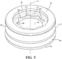
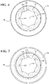
- the upper stopper 72 defines a first orifice 114 bounded by a first periphery 116.
- the first orifice 114 is in fluid communication with the fluid compartment 38.
- the first periphery 116 of the first orifice 114 extends sinusoidally and annularly about the center axis A.
- the first periphery 116 defines a plurality of first peaks 118 and a plurality of first troughs 120 disposed about the center axis A.
- the lower stopper 74 defines a second orifice 122 bounded by a second periphery 124.
- the second orifice 122 is in fluid communication with the gas compartment 36.
- the second periphery 124 of the second orifice 122 extending sinusoidally and annularly about the center axis A.
- the second periphery 124 defines a plurality of second peaks 126 and a plurality of second troughs 128 located about the center axis A.
- the first orifice 114 and the second orifice 122 both can have a flower shape. The flower shape is employed to maximize fluid flow into the gas cup 50 to help improve response to the pressure fluctuation while limiting the movement of the bridging member 106.
Landscapes
- Engineering & Computer Science (AREA)
- General Engineering & Computer Science (AREA)
- Mechanical Engineering (AREA)
- Physics & Mathematics (AREA)
- Fluid Mechanics (AREA)
- Fluid-Damping Devices (AREA)
Applications Claiming Priority (2)
| Application Number | Priority Date | Filing Date | Title |
|---|---|---|---|
| US17/105,474 US11668364B2 (en) | 2020-11-25 | 2020-11-25 | Gas cup for a damper assembly and a damper assembly |
| CN202110210406.2A CN113027973B (zh) | 2020-11-25 | 2021-02-25 | 用于阻尼器组件的气杯和阻尼器组件 |
Publications (2)
| Publication Number | Publication Date |
|---|---|
| EP4006376A1 true EP4006376A1 (de) | 2022-06-01 |
| EP4006376B1 EP4006376B1 (de) | 2025-06-18 |
Family
ID=76461569
Family Applications (1)
| Application Number | Title | Priority Date | Filing Date |
|---|---|---|---|
| EP21208906.4A Active EP4006376B1 (de) | 2020-11-25 | 2021-11-18 | Gasbecher für eine dämpferanordnung und dämpferanordnung |
Country Status (4)
| Country | Link |
|---|---|
| US (1) | US11668364B2 (de) |
| EP (1) | EP4006376B1 (de) |
| JP (1) | JP7137666B2 (de) |
| CN (1) | CN113027973B (de) |
Citations (5)
| Publication number | Priority date | Publication date | Assignee | Title |
|---|---|---|---|---|
| DE1926000A1 (de) * | 1968-05-21 | 1969-11-27 | Girling Ltd | Abdichtender Trennkolben |
| DE2018845A1 (de) | 1970-04-20 | 1971-11-11 | Schmid, Leopold F., 7000 Stuttgart | Trennkolben für hydropneumatische Einrohr- Teleskopschwingungsdämpfer, insbesondere für Kraftfahrzeuge |
| DE2123679B1 (de) * | 1971-05-13 | 1972-09-21 | Trennkolben zwischen gas- und fluessigkeitsraum eines einrohrstossdaempfers | |
| DE4335327A1 (de) * | 1993-10-18 | 1995-04-20 | Bilstein August Gmbh Co Kg | Hydraulischer Einrohrschwingungsdämpfer für Kraftfahrzeuge |
| EP3299193A2 (de) * | 2016-09-22 | 2018-03-28 | BeijingWest Industries Co. Ltd. | Luftfederanordnung |
Family Cites Families (32)
| Publication number | Priority date | Publication date | Assignee | Title |
|---|---|---|---|---|
| US2774446A (en) * | 1952-05-05 | 1956-12-18 | Bourcier Christian Marie Louis | Shock absorbers |
| US3121479A (en) * | 1960-11-10 | 1964-02-18 | Procedo G M B H | Volume compensation devices for hydraulic-pneumatic telescopic shock absorbers |
| DE1142470B (de) * | 1961-11-22 | 1963-01-17 | Boge Gmbh | Hydropneumatischer Einrohr-Schwingungsdaempfer mit Trennkoerper |
| DE1182914B (de) * | 1962-07-16 | 1964-12-03 | Hans Peter Doetsch | Rollmembrankolben |
| US3307842A (en) * | 1964-12-01 | 1967-03-07 | Ellis Fluid Dynamics Corp | Shock absorber |
| US3587789A (en) * | 1968-02-28 | 1971-06-28 | Bilstein August | Hydropneumatic single-cylinder shock absorber |
| JPS5623741U (de) * | 1979-08-01 | 1981-03-03 | ||
| JPS57192645A (en) * | 1981-05-25 | 1982-11-26 | Yamaha Motor Co Ltd | Cylindrical hydraulic buffer |
| JPS58184044U (ja) | 1982-06-02 | 1983-12-07 | トヨタ自動車株式会社 | 液圧緩衝器 |
| US4789192A (en) * | 1985-12-20 | 1988-12-06 | General Motors Corporation | Two-stage variable orifice energy absorber with cylinder cap having radially fixed blow out orifice |
| US4880213A (en) * | 1986-01-30 | 1989-11-14 | Nhk Spring Co., Ltd. | Gas spring apparatus |
| JPS63110701U (de) | 1987-01-12 | 1988-07-16 | ||
| JPH0221041A (ja) * | 1988-07-06 | 1990-01-24 | Kayaba Ind Co Ltd | 油空圧サスペンション用アキュームレータ |
| US5174552A (en) * | 1991-10-15 | 1992-12-29 | Lord Corporation | Fluid mount with active vibration control |
| US5257680A (en) * | 1991-12-20 | 1993-11-02 | Lord Corporation | Surface effect dampers having both hysteresis and a frictional component |
| DE19531794C1 (de) * | 1995-08-30 | 1996-12-19 | Fichtel & Sachs Ag | Kolben-Zylinder-Aggregat |
| US5878851A (en) * | 1996-07-02 | 1999-03-09 | Lord Corporation | Controllable vibration apparatus |
| DE19756443C1 (de) * | 1997-12-18 | 1999-02-11 | Mannesmann Sachs Ag | Trennkolben für ein Schwingungsdämpfungssystem |
| GB9801780D0 (en) * | 1998-01-29 | 1998-03-25 | Rover Group | A roll damper arrangement |
| US6637560B2 (en) * | 2002-02-26 | 2003-10-28 | Delphi Technologies, Inc. | Vehicle damper assembly and method of modulating fluid flow |
| DE10222940C1 (de) * | 2002-05-24 | 2003-07-31 | Zf Sachs Ag | Schwingungsdämpfer mit einem hydraulischen Druckanschlag |
| US6981578B2 (en) * | 2003-07-31 | 2006-01-03 | Troy Leiphart | Non-pressurized monotube shock absorber |
| JP2006226343A (ja) * | 2005-02-16 | 2006-08-31 | Kayaba Ind Co Ltd | アキュムレータおよび緩衝器 |
| US20080314706A1 (en) * | 2007-06-20 | 2008-12-25 | Saiman Lun | Gas cup assembly and damper having same |
| WO2009124743A1 (de) * | 2008-04-08 | 2009-10-15 | Knorr-Bremse Systeme für Nutzfahrzeuge GmbH | Dämpfer mit kompressiblem fluid |
| KR100952776B1 (ko) * | 2008-07-25 | 2010-04-14 | 현대자동차주식회사 | 엔진 마운트 장치 |
| EP2312180B1 (de) * | 2009-10-13 | 2019-09-18 | Fox Factory, Inc. | Vorrichtung zur Steuerung eines hydraulischen Dämpfers |
| DE102012213272A1 (de) * | 2012-07-27 | 2014-05-22 | Zf Friedrichshafen Ag | Trennkolben |
| JP5865514B2 (ja) * | 2012-10-08 | 2016-02-17 | ベイジンウェスト・インダストリーズ・カンパニー・リミテッドBeijingwest Industries Co., Ltd. | ガスカップ潤滑チャンバを有する流体ダンパアッセンブリ |
| US9951837B2 (en) * | 2013-05-22 | 2018-04-24 | Firestone Industrial Products Company, Llc | End member and gas spring assembly including same |
| EP3039313B1 (de) * | 2013-08-27 | 2019-01-09 | BeijingWest Industries Co., Ltd. | Einzelrohrdämpferanordnung |
| CN108087477B (zh) * | 2017-11-29 | 2020-05-08 | 中国直升机设计研究所 | 一种带弹性的浮动活塞 |
-
2020
- 2020-11-25 US US17/105,474 patent/US11668364B2/en active Active
-
2021
- 2021-02-25 CN CN202110210406.2A patent/CN113027973B/zh active Active
- 2021-06-16 JP JP2021100536A patent/JP7137666B2/ja active Active
- 2021-11-18 EP EP21208906.4A patent/EP4006376B1/de active Active
Patent Citations (5)
| Publication number | Priority date | Publication date | Assignee | Title |
|---|---|---|---|---|
| DE1926000A1 (de) * | 1968-05-21 | 1969-11-27 | Girling Ltd | Abdichtender Trennkolben |
| DE2018845A1 (de) | 1970-04-20 | 1971-11-11 | Schmid, Leopold F., 7000 Stuttgart | Trennkolben für hydropneumatische Einrohr- Teleskopschwingungsdämpfer, insbesondere für Kraftfahrzeuge |
| DE2123679B1 (de) * | 1971-05-13 | 1972-09-21 | Trennkolben zwischen gas- und fluessigkeitsraum eines einrohrstossdaempfers | |
| DE4335327A1 (de) * | 1993-10-18 | 1995-04-20 | Bilstein August Gmbh Co Kg | Hydraulischer Einrohrschwingungsdämpfer für Kraftfahrzeuge |
| EP3299193A2 (de) * | 2016-09-22 | 2018-03-28 | BeijingWest Industries Co. Ltd. | Luftfederanordnung |
Also Published As
| Publication number | Publication date |
|---|---|
| US20220163085A1 (en) | 2022-05-26 |
| CN113027973A (zh) | 2021-06-25 |
| JP7137666B2 (ja) | 2022-09-14 |
| EP4006376B1 (de) | 2025-06-18 |
| CN113027973B (zh) | 2022-06-07 |
| US11668364B2 (en) | 2023-06-06 |
| JP2022083962A (ja) | 2022-06-06 |
Similar Documents
| Publication | Publication Date | Title |
|---|---|---|
| US11536344B2 (en) | Valve and shock absorber | |
| US11326663B2 (en) | Damper assembly and a piston for a damper assembly | |
| US10518601B2 (en) | Damper with internal hydraulic stop | |
| US10663027B2 (en) | Damper with valve preload limiter | |
| US11686367B2 (en) | Hydraulic damper and a piston for the hydraulic damper assembly | |
| US11680620B2 (en) | Telescopic damper assembly | |
| US5810130A (en) | Suspension damper with rebound cut-off | |
| US11732771B2 (en) | Hydraulic damper assembly and a piston for a hydraulic damper assembly | |
| WO2007021753A2 (en) | Asymmetrical intake damper valve | |
| WO2014155809A1 (ja) | 圧力緩衝装置 | |
| US7073643B2 (en) | Compensated rod for a frequency dependent damper shock absorber | |
| WO2019182863A1 (en) | Damper with floating piston bleed channel | |
| US11434969B2 (en) | Hydraulic damper assembly including an anti-noise member | |
| US5848677A (en) | Vibration damper for a motor vehicle and a piston cylinder assembly; such as for a vibration damper for a motor vehicle | |
| US20230018887A1 (en) | Telescopic passive damper | |
| US10995815B2 (en) | Damper with flexible floating disc | |
| JP5015071B2 (ja) | 緩衝器 | |
| US11668364B2 (en) | Gas cup for a damper assembly and a damper assembly | |
| EP3992493A2 (de) | Hydraulische dämpferanordnung und kolben für eine hydraulische dämpferanordnung | |
| JP2024037605A (ja) | 防振装置 | |
| WO2023037713A1 (ja) | 緩衝器 | |
| EP4170195B1 (de) | Teleskopischer passiver dämpfer | |
| US20210095736A1 (en) | Cylindrical diaphragm assembly with reduced diameter for hidraulic shock absorbers sealed at both ends, of the type employed in self-closing furniture | |
| JPH0143563Y2 (de) | ||
| JPH09105436A (ja) | ショックアブソーバ |
Legal Events
| Date | Code | Title | Description |
|---|---|---|---|
| PUAI | Public reference made under article 153(3) epc to a published international application that has entered the european phase |
Free format text: ORIGINAL CODE: 0009012 |
|
| STAA | Information on the status of an ep patent application or granted ep patent |
Free format text: STATUS: THE APPLICATION HAS BEEN PUBLISHED |
|
| AK | Designated contracting states |
Kind code of ref document: A1 Designated state(s): AL AT BE BG CH CY CZ DE DK EE ES FI FR GB GR HR HU IE IS IT LI LT LU LV MC MK MT NL NO PL PT RO RS SE SI SK SM TR |
|
| STAA | Information on the status of an ep patent application or granted ep patent |
Free format text: STATUS: REQUEST FOR EXAMINATION WAS MADE |
|
| 17P | Request for examination filed |
Effective date: 20221201 |
|
| RBV | Designated contracting states (corrected) |
Designated state(s): AL AT BE BG CH CY CZ DE DK EE ES FI FR GB GR HR HU IE IS IT LI LT LU LV MC MK MT NL NO PL PT RO RS SE SI SK SM TR |
|
| GRAP | Despatch of communication of intention to grant a patent |
Free format text: ORIGINAL CODE: EPIDOSNIGR1 |
|
| RIC1 | Information provided on ipc code assigned before grant |
Ipc: F16F 9/08 20060101ALN20241204BHEP Ipc: F16F 9/06 20060101AFI20241204BHEP |
|
| STAA | Information on the status of an ep patent application or granted ep patent |
Free format text: STATUS: GRANT OF PATENT IS INTENDED |
|
| INTG | Intention to grant announced |
Effective date: 20250109 |
|
| GRAS | Grant fee paid |
Free format text: ORIGINAL CODE: EPIDOSNIGR3 |
|
| GRAA | (expected) grant |
Free format text: ORIGINAL CODE: 0009210 |
|
| STAA | Information on the status of an ep patent application or granted ep patent |
Free format text: STATUS: THE PATENT HAS BEEN GRANTED |
|
| AK | Designated contracting states |
Kind code of ref document: B1 Designated state(s): AL AT BE BG CH CY CZ DE DK EE ES FI FR GB GR HR HU IE IS IT LI LT LU LV MC MK MT NL NO PL PT RO RS SE SI SK SM TR |
|
| REG | Reference to a national code |
Ref country code: GB Ref legal event code: FG4D |
|
| REG | Reference to a national code |
Ref country code: CH Ref legal event code: EP |
|
| REG | Reference to a national code |
Ref country code: DE Ref legal event code: R096 Ref document number: 602021032395 Country of ref document: DE |
|
| REG | Reference to a national code |
Ref country code: CH Ref legal event code: EP |
|
| REG | Reference to a national code |
Ref country code: IE Ref legal event code: FG4D |
|
| P01 | Opt-out of the competence of the unified patent court (upc) registered |
Free format text: CASE NUMBER: APP_30663/2025 Effective date: 20250626 |
|
| PG25 | Lapsed in a contracting state [announced via postgrant information from national office to epo] |
Ref country code: FI Free format text: LAPSE BECAUSE OF FAILURE TO SUBMIT A TRANSLATION OF THE DESCRIPTION OR TO PAY THE FEE WITHIN THE PRESCRIBED TIME-LIMIT Effective date: 20250618 |
|
| REG | Reference to a national code |
Ref country code: LT Ref legal event code: MG9D |
|
| PG25 | Lapsed in a contracting state [announced via postgrant information from national office to epo] |
Ref country code: GR Free format text: LAPSE BECAUSE OF FAILURE TO SUBMIT A TRANSLATION OF THE DESCRIPTION OR TO PAY THE FEE WITHIN THE PRESCRIBED TIME-LIMIT Effective date: 20250919 Ref country code: NO Free format text: LAPSE BECAUSE OF FAILURE TO SUBMIT A TRANSLATION OF THE DESCRIPTION OR TO PAY THE FEE WITHIN THE PRESCRIBED TIME-LIMIT Effective date: 20250918 |
|
| PG25 | Lapsed in a contracting state [announced via postgrant information from national office to epo] |
Ref country code: BG Free format text: LAPSE BECAUSE OF FAILURE TO SUBMIT A TRANSLATION OF THE DESCRIPTION OR TO PAY THE FEE WITHIN THE PRESCRIBED TIME-LIMIT Effective date: 20250618 |
|
| PG25 | Lapsed in a contracting state [announced via postgrant information from national office to epo] |
Ref country code: HR Free format text: LAPSE BECAUSE OF FAILURE TO SUBMIT A TRANSLATION OF THE DESCRIPTION OR TO PAY THE FEE WITHIN THE PRESCRIBED TIME-LIMIT Effective date: 20250618 |
|
| PGFP | Annual fee paid to national office [announced via postgrant information from national office to epo] |
Ref country code: FR Payment date: 20250930 Year of fee payment: 5 |
|
| PG25 | Lapsed in a contracting state [announced via postgrant information from national office to epo] |
Ref country code: RS Free format text: LAPSE BECAUSE OF FAILURE TO SUBMIT A TRANSLATION OF THE DESCRIPTION OR TO PAY THE FEE WITHIN THE PRESCRIBED TIME-LIMIT Effective date: 20250918 |
|
| REG | Reference to a national code |
Ref country code: NL Ref legal event code: MP Effective date: 20250618 |
|
| PG25 | Lapsed in a contracting state [announced via postgrant information from national office to epo] |
Ref country code: LV Free format text: LAPSE BECAUSE OF FAILURE TO SUBMIT A TRANSLATION OF THE DESCRIPTION OR TO PAY THE FEE WITHIN THE PRESCRIBED TIME-LIMIT Effective date: 20250618 |
|
| PG25 | Lapsed in a contracting state [announced via postgrant information from national office to epo] |
Ref country code: NL Free format text: LAPSE BECAUSE OF FAILURE TO SUBMIT A TRANSLATION OF THE DESCRIPTION OR TO PAY THE FEE WITHIN THE PRESCRIBED TIME-LIMIT Effective date: 20250618 |
|
| PG25 | Lapsed in a contracting state [announced via postgrant information from national office to epo] |
Ref country code: PT Free format text: LAPSE BECAUSE OF FAILURE TO SUBMIT A TRANSLATION OF THE DESCRIPTION OR TO PAY THE FEE WITHIN THE PRESCRIBED TIME-LIMIT Effective date: 20251020 |
|
| REG | Reference to a national code |
Ref country code: AT Ref legal event code: MK05 Ref document number: 1804420 Country of ref document: AT Kind code of ref document: T Effective date: 20250618 |
|
| PG25 | Lapsed in a contracting state [announced via postgrant information from national office to epo] |
Ref country code: IS Free format text: LAPSE BECAUSE OF FAILURE TO SUBMIT A TRANSLATION OF THE DESCRIPTION OR TO PAY THE FEE WITHIN THE PRESCRIBED TIME-LIMIT Effective date: 20251018 |
|
| PGFP | Annual fee paid to national office [announced via postgrant information from national office to epo] |
Ref country code: DE Payment date: 20250930 Year of fee payment: 5 |
|
| PGFP | Annual fee paid to national office [announced via postgrant information from national office to epo] |
Ref country code: GB Payment date: 20251001 Year of fee payment: 5 |
|
| PG25 | Lapsed in a contracting state [announced via postgrant information from national office to epo] |
Ref country code: AT Free format text: LAPSE BECAUSE OF FAILURE TO SUBMIT A TRANSLATION OF THE DESCRIPTION OR TO PAY THE FEE WITHIN THE PRESCRIBED TIME-LIMIT Effective date: 20250618 Ref country code: SM Free format text: LAPSE BECAUSE OF FAILURE TO SUBMIT A TRANSLATION OF THE DESCRIPTION OR TO PAY THE FEE WITHIN THE PRESCRIBED TIME-LIMIT Effective date: 20250618 |
|
| PG25 | Lapsed in a contracting state [announced via postgrant information from national office to epo] |
Ref country code: CZ Free format text: LAPSE BECAUSE OF FAILURE TO SUBMIT A TRANSLATION OF THE DESCRIPTION OR TO PAY THE FEE WITHIN THE PRESCRIBED TIME-LIMIT Effective date: 20250618 |
|
| PG25 | Lapsed in a contracting state [announced via postgrant information from national office to epo] |
Ref country code: PL Free format text: LAPSE BECAUSE OF FAILURE TO SUBMIT A TRANSLATION OF THE DESCRIPTION OR TO PAY THE FEE WITHIN THE PRESCRIBED TIME-LIMIT Effective date: 20250618 |
|
| PG25 | Lapsed in a contracting state [announced via postgrant information from national office to epo] |
Ref country code: EE Free format text: LAPSE BECAUSE OF FAILURE TO SUBMIT A TRANSLATION OF THE DESCRIPTION OR TO PAY THE FEE WITHIN THE PRESCRIBED TIME-LIMIT Effective date: 20250618 |
|
| PG25 | Lapsed in a contracting state [announced via postgrant information from national office to epo] |
Ref country code: RO Free format text: LAPSE BECAUSE OF FAILURE TO SUBMIT A TRANSLATION OF THE DESCRIPTION OR TO PAY THE FEE WITHIN THE PRESCRIBED TIME-LIMIT Effective date: 20250618 Ref country code: SK Free format text: LAPSE BECAUSE OF FAILURE TO SUBMIT A TRANSLATION OF THE DESCRIPTION OR TO PAY THE FEE WITHIN THE PRESCRIBED TIME-LIMIT Effective date: 20250618 |
|
| PG25 | Lapsed in a contracting state [announced via postgrant information from national office to epo] |
Ref country code: ES Free format text: LAPSE BECAUSE OF FAILURE TO SUBMIT A TRANSLATION OF THE DESCRIPTION OR TO PAY THE FEE WITHIN THE PRESCRIBED TIME-LIMIT Effective date: 20250618 |
|
| REG | Reference to a national code |
Ref country code: DE Ref legal event code: R097 Ref document number: 602021032395 Country of ref document: DE |
|
| PG25 | Lapsed in a contracting state [announced via postgrant information from national office to epo] |
Ref country code: DK Free format text: LAPSE BECAUSE OF FAILURE TO SUBMIT A TRANSLATION OF THE DESCRIPTION OR TO PAY THE FEE WITHIN THE PRESCRIBED TIME-LIMIT Effective date: 20250618 |
|
| PG25 | Lapsed in a contracting state [announced via postgrant information from national office to epo] |
Ref country code: IT Free format text: LAPSE BECAUSE OF FAILURE TO SUBMIT A TRANSLATION OF THE DESCRIPTION OR TO PAY THE FEE WITHIN THE PRESCRIBED TIME-LIMIT Effective date: 20250618 |
|
| PLBE | No opposition filed within time limit |
Free format text: ORIGINAL CODE: 0009261 |
|
| STAA | Information on the status of an ep patent application or granted ep patent |
Free format text: STATUS: NO OPPOSITION FILED WITHIN TIME LIMIT |
|
| REG | Reference to a national code |
Ref country code: CH Ref legal event code: L10 Free format text: ST27 STATUS EVENT CODE: U-0-0-L10-L00 (AS PROVIDED BY THE NATIONAL OFFICE) Effective date: 20260430 |