EP4006399A1 - Mécanisme d'entrée d'eau - Google Patents
Mécanisme d'entrée d'eau Download PDFInfo
- Publication number
- EP4006399A1 EP4006399A1 EP20812506.2A EP20812506A EP4006399A1 EP 4006399 A1 EP4006399 A1 EP 4006399A1 EP 20812506 A EP20812506 A EP 20812506A EP 4006399 A1 EP4006399 A1 EP 4006399A1
- Authority
- EP
- European Patent Office
- Prior art keywords
- water
- channel
- silencing
- flow guide
- water outlet
- Prior art date
- Legal status (The legal status is an assumption and is not a legal conclusion. Google has not performed a legal analysis and makes no representation as to the accuracy of the status listed.)
- Pending
Links
Images




Classifications
-
- F—MECHANICAL ENGINEERING; LIGHTING; HEATING; WEAPONS; BLASTING
- F16—ENGINEERING ELEMENTS AND UNITS; GENERAL MEASURES FOR PRODUCING AND MAINTAINING EFFECTIVE FUNCTIONING OF MACHINES OR INSTALLATIONS; THERMAL INSULATION IN GENERAL
- F16L—PIPES; JOINTS OR FITTINGS FOR PIPES; SUPPORTS FOR PIPES, CABLES OR PROTECTIVE TUBING; MEANS FOR THERMAL INSULATION IN GENERAL
- F16L55/00—Devices or appurtenances for use in, or in connection with, pipes or pipe systems
- F16L55/04—Devices damping pulsations or vibrations in fluids
- F16L55/045—Devices damping pulsations or vibrations in fluids specially adapted to prevent or minimise the effects of water hammer
-
- F—MECHANICAL ENGINEERING; LIGHTING; HEATING; WEAPONS; BLASTING
- F16—ENGINEERING ELEMENTS AND UNITS; GENERAL MEASURES FOR PRODUCING AND MAINTAINING EFFECTIVE FUNCTIONING OF MACHINES OR INSTALLATIONS; THERMAL INSULATION IN GENERAL
- F16K—VALVES; TAPS; COCKS; ACTUATING-FLOATS; DEVICES FOR VENTING OR AERATING
- F16K47/00—Means in valves for absorbing fluid energy
- F16K47/02—Means in valves for absorbing fluid energy for preventing water-hammer or noise
-
- E—FIXED CONSTRUCTIONS
- E03—WATER SUPPLY; SEWERAGE
- E03D—WATER-CLOSETS OR URINALS WITH FLUSHING DEVICES; FLUSHING VALVES THEREFOR
- E03D1/00—Water flushing devices with cisterns ; Setting up a range of flushing devices or water-closets; Combinations of several flushing devices
- E03D1/30—Valves for high or low level cisterns; Their arrangement ; Flushing mechanisms in the cistern, optionally with provisions for a pre-or a post- flushing and for cutting off the flushing mechanism in case of leakage
- E03D1/32—Arrangement of inlet valves
-
- F—MECHANICAL ENGINEERING; LIGHTING; HEATING; WEAPONS; BLASTING
- F16—ENGINEERING ELEMENTS AND UNITS; GENERAL MEASURES FOR PRODUCING AND MAINTAINING EFFECTIVE FUNCTIONING OF MACHINES OR INSTALLATIONS; THERMAL INSULATION IN GENERAL
- F16K—VALVES; TAPS; COCKS; ACTUATING-FLOATS; DEVICES FOR VENTING OR AERATING
- F16K47/00—Means in valves for absorbing fluid energy
- F16K47/08—Means in valves for absorbing fluid energy for decreasing pressure or noise level and having a throttling member separate from the closure member, e.g. screens, slots, labyrinths
-
- F—MECHANICAL ENGINEERING; LIGHTING; HEATING; WEAPONS; BLASTING
- F16—ENGINEERING ELEMENTS AND UNITS; GENERAL MEASURES FOR PRODUCING AND MAINTAINING EFFECTIVE FUNCTIONING OF MACHINES OR INSTALLATIONS; THERMAL INSULATION IN GENERAL
- F16L—PIPES; JOINTS OR FITTINGS FOR PIPES; SUPPORTS FOR PIPES, CABLES OR PROTECTIVE TUBING; MEANS FOR THERMAL INSULATION IN GENERAL
- F16L9/00—Rigid pipes
- F16L9/21—Rigid pipes made of sound-absorbing materials or with sound-absorbing structure
-
- E—FIXED CONSTRUCTIONS
- E03—WATER SUPPLY; SEWERAGE
- E03D—WATER-CLOSETS OR URINALS WITH FLUSHING DEVICES; FLUSHING VALVES THEREFOR
- E03D2201/00—Details and methods of use for water closets and urinals not otherwise provided for
- E03D2201/20—Noise reduction features
Definitions
- the invention relates to the technical field of bathroom products, in particular to a water inlet mechanism.
- the water outlet of an AG water inlet valve is a certain distance above the bottom of a water tank, so water will impact the bottom of the water tank when directly flowing down via the water outlet above, thus generating loud noise.
- a silencing pipe is additionally disposed at the water outlet.
- existing silencing pipes are typically hollow pipes, so when water flows out via the water outlet, most of the water still directly falls onto the water surface of the water tank.
- the silencing pipe is similar to a loudspeaker, water impact sounds propagate along the pipe wall and generate loud noise.
- the objective of the invention is to solve the above-mentioned problems by providing a water inlet mechanism.
- a water inlet mechanism comprises a valve body and a silencing element, wherein the valve body is provided with a water outlet, and the silencing element is provided with a silencing channel communicated with the water outlet, and when water flows in, a water flow in the valve body flows through the silencing channel, such that impact force of the water flow is reduced; a buffer element is disposed in the silencing channel, and water in the silencing channel flows out after kinetic energy of the water flow is reduced under the action of the buffer element; and/or, a flow guide element is disposed in the silencing channel, and water in the silencing channel flows out under the flow guide action of the flow guide element.
- the flow guide element is a plurality of flow guide ribs disposed in the silencing channel, and the flow guide ribs extend in an axial direction of the silencing element; and the flow guide ribs collaborate with the silencing element to divide the silencing channel into a plurality of cavities; and the flow guide ribs are spaced apart from each other.
- the buffer element is disposed close to a water inlet of the silencing element, and water in the silencing element flows down along an inner wall of the silencing channel after being buffered by the buffer element.
- the buffer element is a filter screen or a water-stop rib.
- the silencing element is a silencing pipe; or, the silencing element comprises a hollow pipe with an inner cavity forming the silencing channel.
- a water inlet of the silencing element is shaped like a bell mouth with an inner diameter becoming larger gradually from inside to outside.
- the water outlet of the valve body is located over the water inlet of the silencing element and is located above a water level in a water tank; and an air gap exists between the water outlet of the valve body and the water inlet of the silencing channel, and no barrier exists in the air gap.
- the water inlet mechanism further comprises a flow guide element, and when the silencing channel overflows, water flowing over from the silencing channel is guided by the flow guide element.
- the water flowing over from the silencing channel is guided into an inner cavity of a toilet tank by the flow guide element.
- the flow guide element is a flow guide port formed in the silencing channel, and the flow guide port is lower than a water inlet of the silencing channel.
- the flow guide element is located upstream of the buffer element.
- the silencing element is integrally formed on a water-stop cup, used for receiving a control buoy, of the water inlet valve; or, the silencing element is formed separately and is fixedly disposed on the water-stop cup, used for receiving the control buoy, of the water inlet valve; and the water in the silencing channel is guided out of the water-stop cup by the flow guide element.
- the invention further provides another water inlet mechanism, comprising a valve body and a water-stop assembly, the valve body comprising a water inlet channel and a water outlet channel, the water-stop assembly controlling the water inlet channel to be communicated or not communicated with the water outlet channel, wherein the water outlet channel is provided with at least one section of buffer channel communicated with the water outlet channel, and a water flow in the water outlet channel flows out after kinetic energy of the water flow is reduced under the action of the buffer channel.
- another water inlet mechanism comprising a valve body and a water-stop assembly, the valve body comprising a water inlet channel and a water outlet channel, the water-stop assembly controlling the water inlet channel to be communicated or not communicated with the water outlet channel, wherein the water outlet channel is provided with at least one section of buffer channel communicated with the water outlet channel, and a water flow in the water outlet channel flows out after kinetic energy of the water flow is reduced under the action of the buffer channel.
- the water outlet channel is provided with a first flow guide element, and the water flow in the water outlet channel forms a vertical baffle channel under the action of the first flow guide element, and the buffer channel comprises the vertical baffle channel.
- the first flow guide element comprises a water outlet pipe, and the water in the water outlet channel rises along an outer wall of the water outlet pipe and flows down from an inner cavity of the water outlet pipe, such that the vertical baffle channel is formed.
- the water outlet channel is provided with a second flow guide element, and the water flow in the water outlet channel forms a horizontal baffle channel under the action of the second flow guide element, and the buffer channel comprises the horizontal baffle channel.
- the second flow guide element is a baffle plate or a bent pipe.
- the water outlet channel is provided with a first buffer element for applying resistance to the water flow in the water outlet channel, such that the water flow in the water outlet channel forms a first deceleration channel under the action of the first buffer element; and the buffer channel comprises the first deceleration channel.
- the first buffer element comprises a plurality of protrusions arranged in an array, and the protrusions are used for applying resistance to the water flow in the water outlet channel.
- the water outlet channel is provided with a second buffer element for applying resistance to the water flow in the water outlet channel, and the water flow in the water outlet channel forms a second deceleration channel under the action of the second buffer element; and the buffer channel comprises the second deceleration channel.
- the second buffer element comprises a filter screen for applying resistance to the water flow in the water outlet channel.
- the water-stop assembly comprises a top cover disposed on the water outlet channel, the top cover has a side formed with a pressure release hole and a side provided with a water-stop gasket, a plurality of partition plates spaced apart from each other are disposed on the top cover, the partition plates collaborate with the valve body to form a top cover flow guide channel, and the buffer channel comprises the top cover flow guide channel.
- a third flow guide element is disposed at a water outlet end of the water outlet channel, the water flow in the water outlet channel forms an outlet water flow guide channel under the action of the third flow guide element, and the buffer channel comprises the outlet water flow guide channel.
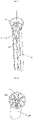
- a water inlet mechanism comprises a valve body 10 and a silencing element 20, wherein the valve body 10 is provided with a water outlet 131, and the silencing element 20 is provided with a silencing channel 21 communicated with the water outlet 131; when water flows in, a water flow in the valve body 10 flows through the silencing channel 21, such that the impact force of the water flow is reduced; and a flow guide element 30 is disposed in the silencing channel 21, and the water in the silencing channel 21 flows out under the flow guide action of the flow guide element 30.
- the flow guide element 30 is a plurality of flow guide ribs disposed in the silencing channel 21, and the flow guide ribs extend in an axial direction of the silencing element 20.
- the flow guide ribs coordinate with the silencing element 20 to divide the silencing channel 21 into a plurality of cavities 21a.
- the silencing element 20 is a silencing pipe.
- a water inlet 22 of the silencing element 20 is shaped like a bell mouth with an inner diameter becoming larger gradually from inside to outside.
- the water outlet 131 of the valve body 10 is located over the water inlet 22 of the silencing element 20 and is located above the water level in a water tank.
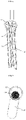
- this embodiment differs from Embodiment 1 mainly in the following aspects: the flow guide ribs are spaced apart from each other, and when water flows in, the water flow in the water inlet channel flows out under the flow guide action of the flow guide ribs.
- this embodiment differs from Embodiment 1 mainly in the following aspects: a buffer element 40 is disposed in the silencing channel 21, and water in the silencing channel 21 flows out after kinetic energy of the water flow is reduced under the buffer action of the buffer element 40.
- water in the silencing element 20 flows down along an inner wall of the silencing channel 21 after being buffered by the buffer element 40.
- the buffer element 40 is a filter screen.
- the buffer element 40 is disposed close to the water inlet 22 of the silencing element 20.
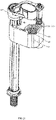
- a water inlet mechanism comprises a valve body 10 and a water-stop assembly, wherein the valve body 10 comprises a water inlet channel 11 and a water outlet channel 12, the water-stop assembly controls the water inlet channel 11 to be communicated or not communicated with the water outlet channel 12, the water outlet channel 12 is provided with at least one section of buffer channel communicated with the water outlet channel 12, and a water flow in the water outlet channel 12 flows out after kinetic energy of the water flow is reduced under the action of the buffer channel.
- the water outlet channel 12 is provided with a first flow guide element, and the water flow in the water outlet channel 12 forms a vertical baffle channel 41 under the action of the first flow guide element, and the buffer channel comprises the vertical baffle channel 41.
- the first flow guide element comprises a water outlet pipe 31, and water in the water outlet channel 12 rises along an outer wall of the water outlet pipe 31 and then flows out downwards from an inner cavity of the water outlet pipe 31, such that the vertical baffle channel 41 is formed.
- a third flow guide element 33 is disposed at a water outlet end of the water outlet channel 12, the water flow in the water outlet channel 12 forms an outlet water flow guide channel under the action of the third flow guide element 33, and the buffer channel comprises the outlet water flow guide channel.
- the third guide element 33 is a plurality of vertical ribs disposed in the water outlet pipe 31, and water in the water outlet pipe 31 flows out under the flow guide action of the vertical ribs.
- the water outlet channel 12 is provided with a second flow guide element, the water flow in the water outlet channel 12 forms a horizontal baffle channel 42 under the action of the second flow guide element, and the buffer channel comprises the horizontal baffle channel 42.
- the second flow guide element is a baffle plate 32 or a bent pipe.
- the second flow guide element is two baffle plates 32 disposed on the outer wall of the water outlet pipe 31, the baffle plates 32 extend in a circumferential direction of the water outlet pipe 31, and the two baffle plates 32 are spaced apart from each other in an axial direction.
- the water outlet channel 12 is provided with a water outlet cavity 13 communicated with the water outlet channel 12, an opening in the bottom of the water outlet cavity 13 forms a water outlet 142 of the water outlet channel 12, and the water outlet pipe 31 is disposed in the water outlet cavity 13 and is communicated with the water outlet 142.
- the water inlet mechanism further comprises a cover 14 which is connected to the water outlet cavity 13 and seals the water outlet cavity 13, such that the water outlet pipe 31 is limited in the water outlet cavity 13.
- the water outlet channel 12 is provided with a second buffer element for applying resistance to the water flow in the water outlet channel 12, the water flow in the water outlet channel 12 forms a second deceleration channel 44 under the action of the second buffer element, and the buffer channel comprises the second deceleration channel 44.
- the second buffer element comprises a filter screen 60 for applying resistance to the water flow in the water outlet channel 12.
- the filter screen 60 is disposed in the water outlet pipe 31.
- the water-stop assembly comprises a top cover 50 disposed on the water outlet channel 12, one side of the top cover 50 is provided with a pressure release hole 51, the other side of the top cover 50 is provided with a water-stop gasket 52, the top cover 50 is provided with a plurality of partition plates 53 which are spaced apart from each other, the partition plates 53 collaborate with the valve body 10 to form a top cover flow guide channel 54, and the buffer channel comprises the top cover flow guide channel 54.
- the partition plates 53 are linear partition plates 53.
- the specific working process of this embodiment is as follows: When water flows into the water inlet valve, water from the water inlet channel 11 flows into the water outlet channel 12, and the water flow in the water outlet channel 12 sequentially flows through the top cover flow guide channel 54, the horizontal baffle channel 42, the vertical baffle channel 41 and the second deceleration channel 44, and finally flows out via the water outlet 142 after kinetic energy of the water flow is gradually reduced under the action of the top cover flow guide channel 54, the horizontal baffle channel 42, the vertical baffle channel 41, and the second deceleration channel 44.
- this embodiment differs from Embodiment 1 mainly in the following aspects: the water inlet mechanism in this embodiment is not provided with the baffle plates 32 on the outer wall of the water outlet pipe 31, and is not provided with the horizontal baffle channel 42 either; and a flow guide part 34 is disposed between the water-stop gasket 52 and the valve body 10 in this embodiment, a water gap is formed between the flow guide part 34 and the valve body 10, and stop ribs 341 are disposed on the flow guide part 34 to buffer the water flow in the water outlet channel 12.
- this embodiment differs from the above embodiment mainly in the following aspects: the water inlet mechanism in this embodiment is not provided with the horizontal baffle channel 42 and the second deceleration channel 44, and the partition plates 53 in this embodiment are arc-shaped partition plates 53; and in this embodiment, the water outlet channel 12 is provided with a first buffer element for applying resistance to the water flow in the water outlet channel 12, such that the water flow in the water outlet channel 12 forms a first deceleration channel 43 under the action of the first buffer element; and the buffer channel comprises the first deceleration channel 43.
- the first buffer element comprises a plurality of protrusions 442 which are arranged in an array, and the protrusions 442 are used for applying resistance to the water flow in the water outlet channel 12.
- the water inlet mechanism further comprises a gland 15 disposed on and connected to the water outlet cavity 13, wherein one end of the gland 15 protrudes upwards to form a hollow receiving cavity 432, the water outlet pipe 31 is disposed in the receiving cavity 432, a flow gap is formed between the water outlet pipe 31 and the receiving cavity 432, protrusions 442 are disposed on a bottom wall of the other end of the gland 15, flow guide ribs 433 are disposed on an inner wall of the receiving cavity 432, and water in the first deceleration channel 43 flows upwards into the water outlet pipe 31 along the flow guide ribs 433.
- the protrusions 442 may be disposed on an inner wall of the water outlet cavity 13.
- the specific working process of this embodiment is as follows: When water flows into the water inlet valve, water from the water inlet channel 11 flows into the water outlet channel 12, and the water flow in the water outlet channel 12 sequentially flows through the top cover flow guide channel 54, the first deceleration channel 43 and the vertical baffle channel 41, and finally flows out via the water outlet 142 after kinetic energy of the water flow is gradually reduced under the action of the top cover flow guide channel 54, the first deceleration channel 43 and the vertical baffle channel 41.
- this embodiment differs from Embodiment 1 mainly in the following aspect: the water inlet mechanism in this embodiment is not provided with the protrusions 442 on the bottom wall of the other end of the gland 15 and is not provided with the first buffer element either.
- the buffer channel of the invention may comprise any one of or a combination of multiples of the top cover flow guide channel 54, the first deceleration channel 43, the horizontal baffle channel 42, the vertical baffle channel 41, and the second deceleration channel 44 to fulfill the objective of the invention.
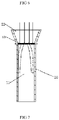
- a water inlet mechanism comprises a valve body 10 and a silencing element 20, wherein the valve body 10 is provided with a water outlet 131, and the silencing element 20 is provided with a silencing channel 21 communicated with the water outlet 131; and when water flows in, a water flow in the valve body 10 flows through the silencing channel 21, such that the impact force of the water flow is reduced.
- the water inlet mechanism further comprises a flow guide element.
- the silencing channel 21 is provided with the flow guide element, so when the silencing channel 21 overflows, the flow guide element guides water flowing over from the silencing channel 21.
- the flow guide element may be disposed in a water tank.
- water flowing over from the silencing channel 21 is guided into an inner cavity of a toilet tank by the flow guide element.
- the flow guide element is a flow guide port 35 formed in the silencing channel 21, and the flow guide port 35 is lower than the water inlet of the silencing channel 21.
- the silencing element 20 comprises a hollow pipe with an inner cavity forming the silencing channel 21, and the flow guide port 35 is a notch formed at the water inlet 22 of the pipe.
- the silencing element 20 comprises a buffer element 40 disposed in the silencing channel 21, water in the silencing channel 21 flows out after kinetic energy of the water flow is reduced under the action of the buffer element 40, and the flow guide element is located upstream of the buffer element 40. Due to the fact that the speed of the water flow in the silencing channel 21 is further decreased by the buffer element 40, the water flow cannot flow away in time when the water pressure is too high, and thus, water may be accumulated upstream of the buffer element 40.
- the flow guide port 35 is arranged to enable water accumulated upstream of the buffer element 40 to flow into the water tank via the flow guide port 35, so that water accumulated around the buffer element 40 is prevented from flowing into a water-stop cup 70 of the water inlet valve, which may otherwise cause water to flow into the water inlet valve in advance.
- the buffer element 40 is a filter screen.
- the buffer element 40 may be a water-stop rib.
- the buffer element 40 is disposed close to the water inlet 22 of the silencing channel 21, and water in the silencing element 20 flows down from the silencing channel 21 after being buffered by the buffer element 40.
- the silencing element 20 is integrally formed on a water-stop cup 70, used for receiving a control buoy, of the water inlet valve.
- the silencing element 20 is formed separately and is fixedly disposed on the water-stop cup 70, used for receiving the control buoy, of the water inlet valve, and water in the silencing channel 21 is guided out of the water-stop cup 70 by the flow guide element.
- the water outlet 131 of the valve body 10 is located over a water inlet 22 of the silencing element 20, and is located above the water level in the water tank.
- an air gap exists between the water outlet 131 of the valve body 10 and the water inlet 22 of the silencing channel 21, and no barrier exists in the air gap.
- the air gap is a gap communicated with the outside atmosphere.
Landscapes
- Engineering & Computer Science (AREA)
- General Engineering & Computer Science (AREA)
- Mechanical Engineering (AREA)
- Health & Medical Sciences (AREA)
- Life Sciences & Earth Sciences (AREA)
- Hydrology & Water Resources (AREA)
- Public Health (AREA)
- Water Supply & Treatment (AREA)
- Details Of Valves (AREA)
Applications Claiming Priority (5)
| Application Number | Priority Date | Filing Date | Title |
|---|---|---|---|
| CN201920775324.0U CN210510724U (zh) | 2019-05-27 | 2019-05-27 | 一种带有改进型消音元件的进水机构 |
| CN201920774601 | 2019-05-27 | ||
| CN201921076039.6U CN210860041U (zh) | 2019-05-27 | 2019-07-10 | 一种降噪进水机构 |
| CN201921518540.3U CN211344212U (zh) | 2019-09-12 | 2019-09-12 | 一种进水阀的消音装置 |
| PCT/CN2020/086614 WO2020238512A1 (fr) | 2019-05-27 | 2020-04-24 | Mécanisme d'entrée d'eau |
Publications (2)
| Publication Number | Publication Date |
|---|---|
| EP4006399A1 true EP4006399A1 (fr) | 2022-06-01 |
| EP4006399A4 EP4006399A4 (fr) | 2024-04-03 |
Family
ID=90055563
Family Applications (1)
| Application Number | Title | Priority Date | Filing Date |
|---|---|---|---|
| EP20812506.2A Pending EP4006399A4 (fr) | 2019-05-27 | 2020-04-24 | Mécanisme d'entrée d'eau |
Country Status (1)
| Country | Link |
|---|---|
| EP (1) | EP4006399A4 (fr) |
Cited By (2)
| Publication number | Priority date | Publication date | Assignee | Title |
|---|---|---|---|---|
| CN116856520A (zh) * | 2023-07-07 | 2023-10-10 | 浙江三棱塑胶有限公司 | 一种不降板排水地漏 |
| CN119732587A (zh) * | 2025-02-20 | 2025-04-01 | 佛山市顺德区美的饮水机制造有限公司 | 饮水设备的出水装置和饮水设备 |
Family Cites Families (9)
| Publication number | Priority date | Publication date | Assignee | Title |
|---|---|---|---|---|
| US2776672A (en) * | 1954-01-25 | 1957-01-08 | Faber Carl Leon | Flush tank valve |
| DE1769798U (de) * | 1958-04-18 | 1958-07-03 | Gebert & Cie | An der austrittsleitung eines spuelkasten-schwimmerventils angebrachter geraeuschdaempfer. |
| JPS5234146U (fr) * | 1976-08-25 | 1977-03-10 | ||
| US4180096A (en) * | 1977-06-23 | 1979-12-25 | J. H. Industries, Inc. | Fill valve |
| US4338964A (en) * | 1980-12-29 | 1982-07-13 | Adolf Schoepe | Side inlet ballcock having flow and structural improvements |
| DE19508258A1 (de) * | 1995-03-08 | 1996-09-12 | Rost & Co Gmbh | WC-Spülkasten-Füllventil |
| CN202831135U (zh) * | 2012-10-12 | 2013-03-27 | 厦门瑞尔特卫浴科技股份有限公司 | 一种补水稳定的进水阀 |
| CN105443856B (zh) * | 2014-06-10 | 2018-01-30 | 厦门威迪亚科技有限公司 | 蓄水式低噪音的进水阀体及防虹吸进水阀进水静音的方法 |
| CN205155336U (zh) * | 2015-11-24 | 2016-04-13 | 厦门瑞尔特卫浴科技股份有限公司 | 一种低噪音进水阀及其降压差结构 |
-
2020
- 2020-04-24 EP EP20812506.2A patent/EP4006399A4/fr active Pending
Cited By (2)
| Publication number | Priority date | Publication date | Assignee | Title |
|---|---|---|---|---|
| CN116856520A (zh) * | 2023-07-07 | 2023-10-10 | 浙江三棱塑胶有限公司 | 一种不降板排水地漏 |
| CN119732587A (zh) * | 2025-02-20 | 2025-04-01 | 佛山市顺德区美的饮水机制造有限公司 | 饮水设备的出水装置和饮水设备 |
Also Published As
| Publication number | Publication date |
|---|---|
| EP4006399A4 (fr) | 2024-04-03 |
Similar Documents
| Publication | Publication Date | Title |
|---|---|---|
| GB2600349A (en) | Water inlet mechanism | |
| CN107532739B (zh) | 真空操作阀 | |
| EP4006399A1 (fr) | Mécanisme d'entrée d'eau | |
| CN110106948B (zh) | 一种防虹吸马桶水箱进水阀 | |
| CN103074927A (zh) | 一种排水增速装置 | |
| US12209401B2 (en) | Gravity-fed toilet with quiet siphonic flush | |
| CN102296687B (zh) | 一种真空辅助抽水马桶 | |
| JP6371945B2 (ja) | 排水トラップ | |
| JP2018112005A (ja) | 水洗大便器 | |
| JP5229692B2 (ja) | シャワーヘッド | |
| WO2021184617A1 (fr) | Dispositif de rinçage de toilettes à bruit réduit | |
| TWM527898U (zh) | 一種用於洗圈的補水器及具有洗圈補水器的馬桶 | |
| JP5446024B2 (ja) | 水洗便器のリム吐水口構造 | |
| CN211774277U (zh) | 一种提高溢流能力及加快排水阀排速的溢流装置 | |
| CN212956794U (zh) | 一种溢流组件 | |
| CN110117978B (zh) | 一种马桶水箱进水阀 | |
| CN211344212U (zh) | 一种进水阀的消音装置 | |
| CN202090408U (zh) | 一种带有消音器的座厕水封补水控制装置 | |
| CN212248549U (zh) | 一种隔离空气的溢流组件 | |
| CN202202388U (zh) | 一种水箱密封真空辅助抽水马桶 | |
| JP4797205B2 (ja) | 排水トラップ | |
| CN210860041U (zh) | 一种降噪进水机构 | |
| JP2013234492A (ja) | フロート式自動真空開閉弁を有する開閉装置 | |
| JP3607250B2 (ja) | 排水騒音の消音装置 | |
| CN107604979B (zh) | 一种不易堵塞的水龙头起泡器 |
Legal Events
| Date | Code | Title | Description |
|---|---|---|---|
| STAA | Information on the status of an ep patent application or granted ep patent |
Free format text: STATUS: THE INTERNATIONAL PUBLICATION HAS BEEN MADE |
|
| PUAI | Public reference made under article 153(3) epc to a published international application that has entered the european phase |
Free format text: ORIGINAL CODE: 0009012 |
|
| STAA | Information on the status of an ep patent application or granted ep patent |
Free format text: STATUS: REQUEST FOR EXAMINATION WAS MADE |
|
| 17P | Request for examination filed |
Effective date: 20220325 |
|
| AK | Designated contracting states |
Kind code of ref document: A1 Designated state(s): AL AT BE BG CH CY CZ DE DK EE ES FI FR GB GR HR HU IE IS IT LI LT LU LV MC MK MT NL NO PL PT RO RS SE SI SK SM TR |
|
| DAX | Request for extension of the european patent (deleted) | ||
| RAV | Requested validation state of the european patent: fee paid |
Extension state: MA Effective date: 20220325 |
|
| A4 | Supplementary search report drawn up and despatched |
Effective date: 20240306 |
|
| RIC1 | Information provided on ipc code assigned before grant |
Ipc: E03D 1/32 20060101ALI20240229BHEP Ipc: F16K 47/08 20060101ALI20240229BHEP Ipc: F16K 47/02 20060101ALI20240229BHEP Ipc: F16L 9/21 20060101ALI20240229BHEP Ipc: F16L 55/045 20060101AFI20240229BHEP |
|
| STAA | Information on the status of an ep patent application or granted ep patent |
Free format text: STATUS: EXAMINATION IS IN PROGRESS |
|
| 17Q | First examination report despatched |
Effective date: 20251028 |