EP4006400B1 - Druckausgleichsvorrichtung - Google Patents
Druckausgleichsvorrichtung Download PDFInfo
- Publication number
- EP4006400B1 EP4006400B1 EP21207222.7A EP21207222A EP4006400B1 EP 4006400 B1 EP4006400 B1 EP 4006400B1 EP 21207222 A EP21207222 A EP 21207222A EP 4006400 B1 EP4006400 B1 EP 4006400B1
- Authority
- EP
- European Patent Office
- Prior art keywords
- piston
- fluid
- pressure
- pressure compensation
- housing
- Prior art date
- Legal status (The legal status is an assumption and is not a legal conclusion. Google has not performed a legal analysis and makes no representation as to the accuracy of the status listed.)
- Active
Links
Images



Classifications
-
- F—MECHANICAL ENGINEERING; LIGHTING; HEATING; WEAPONS; BLASTING
- F16—ENGINEERING ELEMENTS AND UNITS; GENERAL MEASURES FOR PRODUCING AND MAINTAINING EFFECTIVE FUNCTIONING OF MACHINES OR INSTALLATIONS; THERMAL INSULATION IN GENERAL
- F16L—PIPES; JOINTS OR FITTINGS FOR PIPES; SUPPORTS FOR PIPES, CABLES OR PROTECTIVE TUBING; MEANS FOR THERMAL INSULATION IN GENERAL
- F16L55/00—Devices or appurtenances for use in, or in connection with, pipes or pipe systems
- F16L55/04—Devices damping pulsations or vibrations in fluids
- F16L55/045—Devices damping pulsations or vibrations in fluids specially adapted to prevent or minimise the effects of water hammer
- F16L55/05—Buffers therefor
- F16L55/052—Pneumatic reservoirs
- F16L55/053—Pneumatic reservoirs the gas in the reservoir being separated from the fluid in the pipe
-
- A—HUMAN NECESSITIES
- A47—FURNITURE; DOMESTIC ARTICLES OR APPLIANCES; COFFEE MILLS; SPICE MILLS; SUCTION CLEANERS IN GENERAL
- A47J—KITCHEN EQUIPMENT; COFFEE MILLS; SPICE MILLS; APPARATUS FOR MAKING BEVERAGES
- A47J31/00—Apparatus for making beverages
- A47J31/44—Parts or details or accessories of beverage-making apparatus
- A47J31/46—Dispensing spouts, pumps, drain valves or like liquid transporting devices
Definitions
- the invention relates to a pressure compensation device for compensating pressure fluctuations of a fluid in a fluid line, having a housing which has a connection for connecting the fluid line, and a pressure compensation element which is arranged to be movable relative to the housing in order to compensate for the pressure fluctuations.
- the invention further relates to a method for compensating pressure fluctuations of a fluid in a fluid line and to a device, in particular a drinks machine, with a pressure compensation device.
- Pressure compensation devices are used in very different areas of technology and are primarily used when a fluid within fluid lines expands or contracts due to temperature changes. The expansion or contraction of the fluid in the fluid lines leads to pressure fluctuations within the fluid lines, which are partially or completely compensated for by the pressure compensation device so that the line system or the devices connected to it are not impaired or damaged by the pressure fluctuations.
- Known pressure compensation devices have a housing with a connection to which the fluid line, such as a pipe or a hose, is connected. The fluid is fed into the pressure compensation device via the connection.
- a pressure compensation element enables the pressure fluctuations of the fluid in the fluid line to be compensated for by being arranged to be movable relative to the housing and in this way forming a pressure compensation chamber of variable size.
- expansion vessels are often used as pressure compensation devices, in which a flexible membrane arranged within a housing is movably accommodated relative to the housing for the purpose of pressure compensation.
- the fluid lies on one side of the flexible membrane, so that when the pressure of the fluid fluctuates, it is deformed and moved relative to the housing, which results in a variable pressure compensation space and the pressure fluctuation is compensated for accordingly. In this way, the pressure within a heating system is kept essentially constant.
- the membrane on the side opposite the fluid is often additionally exposed to a protective gas, in particular nitrogen.
- the protective gas forms a pressure accumulator that counteracts the pressure of the heating system and also serves to delay embrittlement of the membrane compared to exposure to atmospheric oxygen and thus increase the operating time of the device. Due to the necessary application of nitrogen to the membrane, such pressure compensation devices require a high level of manufacturing effort due to their design, since, for example, the housing must be designed to be gas-tight and with a filling connection, such as a valve.
- the DE 10 2015 203 231 A1 shows a vibration absorber with a volume recording that is not linear.
- the GB 1 456 274 A shows a braking device for vehicle brakes.
- the US 6,997,523 B1 shows a fluid damping system, also for vehicle brakes.
- the AU 2014364880 B2 shows a pressure reducing device with a piston arranged to be movable against a pressure chamber. From the US 5,385,172 a pressure compensation device for fluidic applications with a movable piston is known.
- the EP 2 067 423 A shows a multi-function valve for beverage machines.
- the present invention is therefore based on the object of creating a pressure compensation device which is characterized by a simple structure.
- the design of the pressure compensation element as a movable piston results in a simple structure of the pressure compensation device.
- the pressure compensation devices can be manufactured inexpensively and used for a variety of applications. Complex assembly and manufacturing measures, such as sealing a membrane between two housing halves or applying protective gas on one side, as is required in solutions known from the prior art, are eliminated.
- the piston moves relative to the housing, creating a pressure compensation chamber of variable size, through which the pressure fluctuations are compensated.
- the piston can be moved back and forth between two stops.
- the stops can be used to limit the movement of the piston in that the stops determine positions of the piston in which the piston hits one of the stops. It is possible to use the stops to define the pressure compensation space, in particular the maximum pressure compensation space.
- One of the stops can determine the movement of the piston at a high pressure of the fluid in the fluid line.
- the other stop can determine the movement of the piston at a low pressure of the fluid in the fluid line.
- At least one stop can be designed as a component of the housing, in particular as a component of the connection.
- At least a stop, in particular both stops can be designed as a stop surface.
- the fluid side of the piston can correspond to an end face of the piston.
- the dry side may correspond to the opposite end face of the piston. It is possible for the dry side of the piston in particular to be subjected to a force, such as the spring force of a spring, in addition to the ambient pressure.
- the piston is guided in a piston receptacle.
- the piston holder allows the movement of the piston to be controlled in a structurally simple manner.
- the piston receptacle can be designed as part of the housing or alternatively as a separate component.
- the design as part of the housing can reduce the number of individual parts of the pressure compensation device.
- the piston receptacle can be designed as a lid or cap, with the piston being able to be accommodated within the piston receptacle.
- the piston receptacle can be cup-shaped.
- the piston can be guided coaxially to the main axis of the piston receptacle.
- the piston can be guided linearly within the piston holder.
- the piston is sealed from the piston receptacle using sealing means.
- the sealants can be designed differently.
- one of the sealing means is designed as a circumferential seal and the other sealing means is designed as a surface seal on the end face.
- the circulating seal can be arranged on the lateral surface of the piston.
- the surface seal can be arranged on an end face, in particular on the dry side of the piston. It is possible that the surface seal improves the sealing effect, particularly at high pressures of the fluid in the fluid line.
- the sealants can be designed as an O-ring.
- the piston receptacle advantageously has a pressure compensation opening on the dry side of the piston.
- a constant pressure which corresponds in particular to the ambient pressure, can be achieved on the dry side of the piston.
- the pressure equalization opening it is possible for the pressure equalization opening to be designed as a hole. In the case of a piston receptacle designed as a cup-shaped lid or cap, it is possible for the pressure equalization opening to be arranged at the bottom of the piston receptacle.
- the piston receptacle and the piston form an assembly unit that can be permanently mounted on the housing.
- the non-detachable connection ensures fluid-tight assembly on the housing.
- the assembly unit can be mounted on the housing in just one assembly step, whereby the assembly effort of the pressure compensation device can be reduced.
- the piston can be inserted into the piston holder.
- the piston receptacle it is possible for the piston receptacle to have at least one fastening means for permanent fastening to the housing, which is used to mount the Assembly unit is used.
- the fastening means can be designed as a snap or latching hook or in the manner of an adhesive connection.
- the mounting unit is possible for the mounting unit to be pluggable or clip-mounted on the housing, in particular on a connection.
- the mounting unit can be detachably mounted on the housing.
- the assembly unit can be detachably mounted on the housing, in particular on a connection, in a pluggable, clipped or screwed manner.
- the fastening means can be designed as a detachable snap or latching hook or in the manner of a thread.
- a further advantageous embodiment of the invention provides that the piston receptacle is sealed on the circumference from the housing via a seal.
- the seal can be designed as a circumferential seal, in particular as an O-ring. It is possible for the seal to be arranged on the circumference of the lateral surface of the piston receptacle.
- the assembly unit is mounted on a connection of the housing.
- the additional connection allows the assembly unit, i.e. the piston holder and the piston, to be mounted on the housing in an easy-to-assemble manner.
- a fluid line can be connected to the first connection of the pressure compensation device, the assembly unit can be mounted on the further connection, for example by clipping, plugging or screwing.
- the connection can be designed as a quick connector connection for quick assembly. Using the quick connector connection, the assembly unit can be mounted directly on the connection without any additional tools.
- connection of the assembly unit and the connection of the fluid line are designed to be identical in construction and the assembly unit can optionally be mounted on one of the connections. Due to the identical design of the connections, it is possible to adapt the pressure compensation device particularly flexibly to the respective application by optionally mounting the assembly unit on one of the connections. For example, it is conceivable that the assembly unit is connected to the first connection and the fluid line to the second connection. Alternatively, it is also possible to arrange the fluid line on the first connection and the assembly unit on the second connection. Due to the identical design of the connections, for example as quick connector connections, the structure of the pressure compensation device is simplified. It is possible for both connections to be designed as cup-shaped connections.
- the quick connector can have a clamping element and a release actuation.
- the clamping element can be designed as a clamping ring, which, in the case of a fluid line received in the connection, such as a pipe or a hose, fastens the fluid line in a clamping manner in the connection.
- the release actuation can be actuated by a user, thereby releasing the clamping attachment of the clamping element and dismantling the fluid line from the connection.
- the release actuation can be designed as a pressure actuation.
- connection can be designed as a, in particular cup-shaped, quick connector connection. It is possible for the quick connector to be removable at the fluid line connection. This allows the connection of the fluid line to be optionally connected the assembly unit can be converted. In connection with the design of the quick connector, it is possible in particular for the connection of the fluid line to further have a sealant which can seal the fluid line from the connection.
- the connections each have at least two stop surfaces spaced apart in the axial direction, the position of the assembly unit being able to be determined via one stop surface and the position of the fluid line being able to be determined via the other stop surface.
- the stop surfaces can be formed by changing the cross section of the respective connection.
- the stop surface for determining the position of the fluid line can have a dual function. It is therefore possible for the stop surface to determine the position of the fluid line to simultaneously be designed as a stop of the piston to limit the movement of the piston.
- the housing is advantageously designed in one piece.
- the housing can be designed as an I-, L-, X-, Y- or T-shaped housing. Other shapes are also possible. It is possible for the I- or L-shaped housing to have two connections for connecting a fluid line and the mounting unit. It is also possible for the T-shaped housing to have three connections to which fluid lines and the assembly unit can optionally be connected.
- the housing is designed as a flow-through housing with a third connection for connecting a second fluid line.
- This configuration allows the pressure compensation device to be connected to several fluid lines in a particularly simple manner. So it is possible for the fluid to flow from one fluid line can flow out through the housing to the other fluid line.
- the third connection can be designed to be identical to one or both connections.
- the mounting unit or the piston receptacle can be mounted on the third connection of the housing. It is possible for the pressure compensation device with the housing designed as a flow housing to serve as a fluid line connector.
- the housing As an alternative to the design as a flow housing, it is also possible to design the housing as a storage space housing in which the fluid accumulates from the connection of the fluid line to the assembly unit or the piston receptacle.
- a further advantageous embodiment of the invention provides an indicator arranged on the piston to display the pressure in the fluid line.
- the indicator shows the pressure in the fluid line by changing its position depending on the pressure of the fluid in the fluid line.
- the indicator is arranged on an end face of the piston, in particular on the dry side of the piston.
- the piston can be moved depending on the pressure in the fluid line, so that the indicator on the end face can display different pressures in the fluid line.
- the indicator is designed as an indicator pin, in particular arranged on the end face of the piston.
- the indicator pin can be moved with the piston through the pressure equalization opening.
- the pressure equalization opening fulfills a double function.
- the indicator can be designed in one piece as part of the piston.
- the indicator can have colored components, for example a colored surface. It is also conceivable that the indicator serves as a trigger element of a mechanical and/or electrical switch, which, for example, enables the pressure within the fluid line to be monitored.
- the piston is biased towards its fluid side via a spring arranged on its dry side.
- a spring arranged on its dry side.
- the minimum pressure required in the fluid line, from which the piston is moved relative to the housing, can be determined in a structurally simple manner.
- the spring can be designed as a compression spring.
- the spring can form part of the assembly unit.
- the spring can be accommodated in the, in particular cup-shaped, piston receptacle. It is possible that the spring biases the piston relative to the piston seat. It is possible for the spring to be supported on one side relative to one of the stops for determining the movement of the piston.
- the indicator arranged on the end face of the piston, in particular the indicator pin to be movable inside the spring along the main axis of the spring.
- the piston has a spring receptacle for receiving the compressed spring.
- the spring holder can at least partially or completely accommodate the spring in its compressed state. This maintains the functionality of the stop for determining the movement of the piston.
- the spring receptacle can be designed to correspond to the spring.
- the spring holder can be arranged on an end face of the piston, in particular on its dry side.
- the spring holder can be designed as a circumferential groove on one end face of the piston.
- the piston has a recess on its fluid side.
- the recess can be arranged on an end face of the piston.
- the recess can be designed as a hole, in particular a blind hole.
- the main axis of the recess can run coaxially with the main axis of the piston.
- a device in particular a drinks machine, with a boiler for heating a fluid, a main valve for removing the Fluids via a fluid line and a pressure compensation device for compensating for pressure fluctuations of the fluid in the fluid line as a result of temperature fluctuations of the fluid suggested that the pressure compensation device has one or more of the above features.
- the main valve is designed as a direct-switching valve.
- the valve can be designed as a 3/2-way valve. This makes it possible for the valve to relieve the fluid line outlet in order to completely empty the fluid outlet, for example when a beverage is removed.
- the main valve As an alternative to the design as a direct-switching valve, it is also possible for the main valve to be designed as a servo valve that can be actuated by its own medium, in particular as a diaphragm valve. It is possible that the servo valve can be actuated via a pilot valve. A design as a directly switchable membrane valve is also possible.
- the pressure compensation element designed as a piston is moved to form a variable pressure compensation space.
- the pressure compensation device can have one or more of the features mentioned above. This results in the advantages discussed in connection with the pressure compensation device.
- the Fig. 1 and 2 each show a schematic view of a drinks machine 30, which can be, for example, a fully automatic coffee machine.
- the drinks machine 30 points according to Fig. 1 a boiler 31 designed as a pressure boiler, which in the exemplary embodiment heats water as fluid F, which is used to prepare hot drinks such as coffee, tea or the like.
- the boiler 31 is connected via a fluid line 100 to a main valve 32, via which the water heated in the boiler 31 can be removed from the drinks machine 30, for example into a cup 33.
- the main valve 32 is designed as a direct-switching valve and opens and closes by a sealing element 34 made of an elastic material releasing or closing a valve seat 35.
- the main valve 32 is designed as a 3/2-way valve, which allows the fluid line outlet 101 to be completely emptied when the beverage is removed.
- the main valve 32 has a channel, not shown, which ventilates the fluid line outlet 101 when the main valve 32 is closed, whereby it can be completely emptied.
- the water in the boiler 31 is first heated, led via the fluid line 100 to the main valve 32 and removed there via the main valve 32.
- the main valve 32 is then closed, for example as a sealing ring or surface seal designed sealing element 34 closes the valve seat 35.
- the fluid F in the fluid line 100 is thereby trapped between the boiler 31 and the closed main valve 32 and gradually begins to cool. Due to the associated change in volume of the water, the pressure conditions change and a negative pressure is created in the fluid line 100. Due to this pressure fluctuation, the main valve 32 and in particular its sealing element 34 are increasingly pressed onto the valve seat 35. As a result, damage to the sealing element 34 can occur over time and the service life of the drinks machine 30 can be impaired or comparatively narrow maintenance intervals may be required.
- the drinks machine is 30 according to Fig. 2 in the area between the boiler 31 and the main valve 32 is equipped with a pressure compensation device 1, via which such pressure fluctuations are compensated for.
- the structure and operation of the pressure compensation device 1 will be discussed in more detail below, with it being pointed out that not only negative pressures but also excess pressures can be compensated for via the pressure compensation device 1.
- the Fig. 3 shows the pressure compensation device 1 according to Fig. 2 in an enlarged, partially sectioned view.
- the pressure compensation device 1 has a housing 2 designed in one piece.
- the housing 2 is designed as a flow housing through which the fluid F flows.
- the housing 2 has three identical, pot-shaped connections 3.
- the connections 3 are arranged relative to one another in such a way that the housing 2 has a T-shaped shape.
- a fluid line 100 is connected to two axially oppositely arranged connections 3, so that the fluid F flows axially through the housing 2.
- These connections 3 are quick connector connections designed and each have a quick connector 24 for connecting the fluid lines 100.
- the quick connector 24 is formed from a clamping element 26 designed as a clamping ring and a pressure-operated release actuation 25.
- the release actuation 25 is designed as a release ring, see also 5 and 6 .
- the fluid line 100 for example a pipe or a hose, can be connected to the respective connection 3 without tools and removed again via the quick connectors 24 of the connections 3.
- a seal 27 for example an O-ring, is arranged within the connections 3 as part of the quick connector 24.
- connection 3 does not have a quick connector 24, but could also be equipped with one since the three connections 3 are constructed identically.
- the piston receptacle 8 is designed in one piece as a socket with a cup-shaped cross section. To attach the piston receptacle 8 to the connection 3, the piston receptacle 8 has fastening means 10 arranged on the circumference.
- the fasteners 10 are according to Fig. 3 designed as a locking hook.
- the piston receptacle 8 is fastened in the connection 3 in a latching manner.
- other types of fastening are also conceivable, for example by screwing, clamping, gluing or similar.
- the piston receptacle 8 is sealed from the connection 3 via a seal 13.
- the seal 13 is designed as an O-ring and is arranged on the circumference on the outside of the piston receptacle 8.
- the seal 13 acts as a radial seal.
- the piston receptacle 8 has a circumferential groove 17 to accommodate the seal 13.
- a piston 4 is movably mounted within the cup-shaped piston receptacle 8.
- the piston 4 and the piston receptacle 8 together form an assembly unit 19.
- the assembly unit 19 enables particularly simple assembly in that it can be mounted on a connection 3 in a single assembly step. For example, it is conceivable that the assembly unit 19 is inserted into the connection 3 and then locked via the fastening means 10 of the piston receptacle 8.
- the assembly unit 19 could alternatively also be arranged on one of the other two connections 3, for example in order to adapt the pressure compensation device 1 to an application.
- the assembly unit 19 is permanently mounted on the housing 2. This prevents the assembly unit 19 from being detached from the housing 2 in the event of pressure fluctuations in the fluid F, in particular in the event of excess pressure, in the fluid lines 100.
- the non-detachable assembly prevents leaks due to pressure fluctuations.
- the connections 3 each have two stop surfaces 20, 21.
- the stop surfaces 20, 21 are designed as annular stop surfaces and are arranged one behind the other in the axial direction of the connections 3.
- the assembly unit 19 can be easily mounted via the one stop surface 20. In the event that a fluid line 100 is connected to a connection 3, the seal 27 rests on the stop surface 20 of the connection 3.
- the other stop surface 21 enables a defined insertion of the fluid line 100 when it is mounted on the connection 3.
- the fluid line 100 is along the main axis of the connection 3 up to the Stop surface 21 pushed in.
- the stop surface 21 limits the connection 3 in the axial direction. In the event that a mounting unit 19 is connected to the connection 3, the stop surface 21 allows the movement of the piston 4 to be limited.
- the diameter of the piston 4 is designed to be essentially the same as the diameter of the stop surface 21.
- connections 3 are divided into two areas, a mounting area 28 and a receiving area 29 oriented towards the center of the housing.
- the areas 28, 29 are delimited by the stop surfaces 20, 21.
- the mounting area 28 enables the arrangement of the quick connector 24 in the connection 3.
- the mounting area 28 is designed such that a seal 27, a clamping element 26 and a release actuation 25 can be fastened one behind the other in the connection 3 in the axial direction.
- the assembly area 28 is designed essentially cylindrical and has a gradation towards the receiving area 29, which simplifies the assembly of the quick connector 24. The gradation corresponds to Fig. 3, 4 the stop surface 20.
- the mounting area 28 enables the mounting of the mounting unit 19.
- the mounting unit 19 is inserted in the axial direction into the mounting area 28 until it rests on the step comes.
- the receiving area 29 borders the mounting area 28 and allows the fluid line 100 to be received.
- the receiving area 29 is cylindrical and has a smaller diameter than the mounting area 28.
- the receiving area 29 also has a gradation which corresponds to the stop surface 21.
- the piston 4 can be moved into the receiving area 29.
- the piston 4 is therefore designed in such a way that the piston 4 can be moved into the receiving area 29.
- the diameter of the piston 4 is essentially the same as the diameter of the receiving area 29.
- the maximum pressure compensation space R can be determined via the size of the receiving area 29.
- the essentially cylindrical piston 4 is sealed from the piston receptacle 8 via several sealants, although it would also be possible here to provide a single sealant.
- a first seal 11 designed as an O-ring is provided on the circumference on the outer surface of the piston 8. To arrange the seal 11 on the outer surface of the piston 4, it has a circumferential groove 5 in which the seal 11 is arranged.
- a seal 12 designed as an O-ring is arranged on the end face of the piston 4.
- the sealing means 11, 12 designed as redundant seals can ensure a sufficient sealing effect even in the event of high pressure fluctuations or pressure peaks within the fluid lines 100.
- the sealing means 11, 12 and the seal 13 can be components of the assembly unit 19. In addition, the seal 12 can continue to guarantee the sealing effect in the event of wear of the seal 11.
- the piston 4 mounted in the piston receptacle 8 has a fluid side 22.
- the piston 4 has a dry side 23.
- the fluid side 22 of the piston 4 is the side that faces the fluid F.
- the piston 4 is in contact with the fluid F, which is why the fluid pressure is present on the fluid side 22.
- the dry side 23 opposite the fluid side 22 faces away from the fluid F and is dry.
- two seals 11, 12 are arranged on the piston 4, which seal the fluid side 22 and the dry side 23 from one another.
- a pressure compensation opening 9 serves to equalize the pressure inside the piston receptacle 8 on the dry side 23 of the piston 4 with the ambient pressure.
- the movement of the piston 4 mounted in the piston receptacle 8 is limited by stops 6, 7, see also Fig. 4 .
- the stop 6 is designed as part of the piston receptacle 8 and limits the movement of the piston 4 in one direction, as shown Fig. 3 up.
- the stop 7 is designed as part of the housing 3 and limits the movement of the piston 4 in the opposite direction as shown Fig. 3 downward.
- the stop 7 arranged on the housing 3 corresponds to the stop surface 21.
- the stops 6, 7 are designed as annular surfaces against which the piston 4 abuts flatly.
- the piston 4 also has an indicator 14 arranged on the dry side 23, the functionality of which will be discussed below in connection with 5 and 6 will be discussed in more detail.
- the indicator 14 is designed as a cylindrical indicator pin, although different configurations are also possible here, for example as a cone-shaped indicator pin, as a color indicator, as an acoustic indicator or other optical indicators.
- the piston 4 In the Fig. 3 the piston 4 is in a first position.
- the pressure of the fluid F in the fluid lines 100 is equal to or greater than the ambient pressure, which is why the piston 4 is moved into the first position. This is the case, for example, when operating the drinks machine 30, cf. Fig. 2 .
- a pressure compensation chamber R is formed below the piston 4. The pressure compensation chamber R is variable depending on the position of the piston 4. In the first position of the piston 4, the pressure compensation chamber R is at its maximum size.
- the pressure compensation device 1 can compensate for pressure fluctuations in the fluid F. Pressure fluctuations can occur, for example, when the fluid F cools and the volume of the fluid F within the fluid lines 100 reduces. This is the case, for example, when the drinks machine 30 is switched off if the fluid F is no longer tempered via the boiler 31, cf. also Fig. 2 . Due to the falling pressure, the piston 4 is moved from the first position in the piston holder 8 Fig. 3 sucked below. This reduces the pressure compensation space R and compensates for the change in volume of the fluid F. The movement of the piston 4 creates a pressure equilibrium between the pressures prevailing on the fluid side 22 and the dry side 23. It is possible for the piston 4 to assume a position between the first position in which the piston 4 abuts the stop 6 and the second position in which the piston 4 abuts the stop 7.
- the piston 4 is in the second position. From this second position, the pressure compensation device 1 can also compensate for pressure fluctuations in the fluid F. For example, it is conceivable that the fluid F is heated, which results in an increase in the volume of the fluid F within the fluid lines 100. As a result, the pressure within the fluid lines 100 increases and the piston 4 is used to compensate Fig. 4 moved above. As a result, the pressure equalization space R is enlarged accordingly. Here too, a pressure equilibrium is established across the piston 4.
- the size of the pressure compensation chamber R corresponds to the maximum volume change of the fluid F, which can be compensated for by the pressure compensation device 1.
- the piston 4 In its second position, the piston 4 emerges at least partially from the piston receptacle 8, whereby a larger pressure compensation chamber R can be realized.
- Fig. 5 and Fig. 6 the pressure compensation device 1 is shown in a perspective view from the outside.
- the piston 4 is in the first position according to Fig. 3 and in Fig. 6 in the second position accordingly Fig. 4 .
- the fluid lines 100 have not been shown in these figures.
- the indicator 14 designed as an indicator pin in an easily recognizable signal color, is arranged on the dry side 23 of the piston 4, cf. Fig. 3, 4 .
- the indicator 14 In the first position of the piston 4 according to Fig. 5 the indicator 14 is moved through the pressure equalization opening 9 of the piston receptacle 8. This means that a user can see from the indicator 14 that the piston 4 is in the first position.
- the pressure equalization opening 9 therefore has a dual function. On the one hand, as explained above, this balances the pressure on the dry side 23 of the piston 4 compared to the environment. On the other hand, this interacts with the indicator 14 and allows the position of the piston 4 to be read from outside the piston receptacle 8.
- the indicator 14 In the second position of the piston 4 according to Fig. 6 the indicator 14 is not moved through the pressure equalization opening 9 and is therefore not visible from the outside. It is possible for the indicator 14 to also indicate intermediate positions of the piston 4, for example by the indicator pin not being completely moved through the pressure compensation opening 9. In this context, it is possible for the indicator pin to have a scale which shows the position, in particular the intermediate position, of the piston 4.
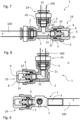
- Fig. 7 to 9 show further exemplary embodiments of pressure compensation devices 1 according to the invention. The following will focus primarily on the differences from the pressure compensation device discussed above Fig. 3 To be received.
- the pressure compensation device 1 shown is identical in construction to the pressure compensation device 1 Fig. 3 designed, wherein the mounting unit 19 is mounted on a connection 3 opposite the fluid line 100.
- the result is a flow housing that is angled at 90°.
- the assembly unit 19 can be optionally mounted on any connection 3. If, for example, the assembly unit 19 is to be mounted from the right-hand connection 3 in the illustration to the upper connection 3, then the quick connector 24 mounted on the upper connection 3 would first have to be removed, the assembly unit 19 would have to be dismantled from the right-hand connection 3 and then attached to it top connection 3 to be mounted. The quick connector 24 could then be mounted on the right-hand connection 3.
- the housing 2 is designed as a storage housing.
- the housings 2 therefore each only have two connections 3.
- the assembly unit 19 formed from piston 4 and piston receptacle 8 is arranged at one of the connections 3, the left-hand connection 3 in the illustrations.
- a fluid line 100 is arranged at the other connection 3.
- connection 3 of the fluid line 100 is according to the exemplary embodiment Fig. 8 , as explained above, designed as a quick connector connection with a quick connector 24. Furthermore, the housing 2 is L-shaped here.
- connection 3 of the fluid line 100 is designed as a plug-in connection onto which the fluid line 100, for example a hose, can be easily plugged.
- the housing 2 is designed here I-shaped.
- a pressure compensation device 1 which is essentially identical in construction to that in Fig. 7 pressure compensation device 1 shown, but has a spring-loaded piston 4.
- the pressure compensation device 1 has a spring 15 serving as a return spring.
- the spring 15 is part of the assembly unit 19.
- the spring 15 is arranged on the dry side 23 of the piston 4.
- the dry side 23 of the piston 4 is now subjected to the spring force of the spring 15 in addition to the ambient pressure of the environment U.
- the response of the piston 4 can be adjusted via the spring 15.
- Fig. 10 It can be seen that the spring 15 is received in its compressed state by a spring receptacle 18. This makes it possible for the piston 4 to continue to strike the stop 6. The first position of the piston 4 therefore does not change due to the arrangement of the spring 15.
- the spring receptacle 18 is designed as a circumferential groove which is arranged on the end face of the piston 4.
- the piston 4 If the operating pressure, such as 4 bar, is generated in the fluid lines 100, the piston 4 initially remains in the position shown Fig. 11 .
- the spring 15 must be selected according to the desired operating pressure. If there is now a sudden increase in pressure of the fluid F within the fluid line 100, i.e. an undesirable pressure peak, this can be caused by moving the piston 4 towards the first position Fig. 10 can be compensated for by enlarging the pressure compensation chamber R accordingly.
- the pressure compensation devices 1 described are characterized by a pressure compensation element designed as a movable piston 4 to form a variable pressure compensation chamber R, which results in a particularly simple structure of the pressure compensation devices 1.
Landscapes
- Engineering & Computer Science (AREA)
- General Engineering & Computer Science (AREA)
- Food Science & Technology (AREA)
- Mechanical Engineering (AREA)
- Measuring Fluid Pressure (AREA)
- Supply Devices, Intensifiers, Converters, And Telemotors (AREA)
- Control Of Fluid Pressure (AREA)
- Vehicle Body Suspensions (AREA)
- Measuring Pulse, Heart Rate, Blood Pressure Or Blood Flow (AREA)
- Fluid-Pressure Circuits (AREA)
Description
- Die Erfindung betrifft eine Druckausgleichsvorrichtung zum Ausgleich von Druckschwankungen eines Fluids in einer Fluidleitung mit einem Gehäuse, das einen Anschluss zum Anschließen der Fluidleitung aufweist, und einem Druckausgleichselement, das zum Ausgleich der Druckschwankungen gegenüber dem Gehäuse bewegbar angeordnet ist. Die Erfindung betrifft ferner ein Verfahren zum Ausgleich von Druckschwankungen eines Fluids in einer Fluidleitung sowie eine Vorrichtung, insbesondere einem Getränkeautomaten, mit einer Druckausgleichsvorrichtung.
- Druckausgleichsvorrichtungen werden in ganz unterschiedlichen Bereichen der Technik verwendet und vor allem dann eingesetzt, wenn ein Fluid innerhalb von Fluidleitungen aufgrund von Temperaturänderungen expandiert oder kontrahiert. Durch die Expansion bzw. Kontraktion des Fluids in den Fluidleitungen kommt es zu Druckschwankungen innerhalb der Fluidleitungen, welche durch die Druckausgleichsvorrichtung teilweise oder vollständig ausgeglichen werden, damit das Leitungssystem oder die an dieses angeschlossenen Vorrichtungen durch die Druckschwankungen nicht beeinträchtigt oder beschädigt werden.
- Bekannte Druckausgleichsvorrichtungen weisen ein Gehäuse mit einem Anschluss auf, an welchen die Fluidleitung, wie beispielsweise ein Rohr oder ein Schlauch, angeschlossen wird. Über den Anschluss wird das Fluid in die Druckausgleichsvorrichtung hineingeführt. Im Inneren der Druckausgleichsvorrichtung ermöglicht ein Druckausgleichselement den Ausgleich der Druckschwankungen des Fluids in der Fluidleitung, indem dieses gegenüber dem Gehäuse bewegbar angeordnet ist und auf diese Weise einen Druckausgleichsraum variabler Größe bildet.
- Im Bereich der Heizungstechnik werden beispielsweise Ausdehnungsgefäße häufig als Druckausgleichsvorrichtungen verwendet, bei denen eine innerhalb eines Gehäuses angeordnete, flexible Membrane zum Zwecke des Druckausgleichs gegenüber dem Gehäuse bewegbar aufgenommen ist. Auf der einen Seite der flexiblen Membrane liegt das Fluid an, so dass diese bei einer Druckschwankung des Fluids verformt und gegenüber dem Gehäuse bewegt wird, wodurch sich ein variabler Druckausgleichsraum ergibt und die Druckschwankung entsprechend ausgeglichen wird. Der Druck innerhalb eines Heizungssystems wird auf diese Weise im Wesentlichen konstant gehalten.
- Bei solchen Druckausgleichsvorrichtungen wird die Membrane an der dem Fluid gegenüberliegenden Seite häufig zusätzlich mit einem Schutzgas, insbesondere Stickstoff, beaufschlagt. Das Schutzgas bildet einen dem Druck des Heizungssystems entgegenwirkenden Druckspeicher und dient ferner dazu, eine Versprödung der Membrane im Vergleich zu einer Beaufschlagung mit Luftsauerstoff zu verzögern und so die Einsatzzeit der Vorrichtung zu erhöhen. Aufgrund der erforderlichen Beaufschlagung der Membrane mit Stickstoff erfordern derartige Druckausgleichsvorrichtungen bauartbedingt einen hohen Fertigungsaufwand, da beispielsweise das Gehäuse gasdicht und mit einem Befüllanschluss, wie beispielsweise einem Ventil, auszugestalten ist.
- Die
DE 10 2015 203 231 A1 zeigt einen Schwingungstilger mit einer Volumenaufnahme, die nicht linear ausgeführt ist. DieGB 1 456 274 A US 6,997,523 B1 zeigt ein Fluiddämpfungssystem, ebenfalls für Fahrzeugbremsen. DieAU 2014364880 B2 US 5,385,172 ist eine Druckausgleichsvorrichtung für fluidische Anwendungen mit einem bewegbaren Kolben bekannt. DieEP 2 067 423 A zeigt ein Mehrfunktionenventil für Getränkemaschinen. - Obschon bekannte Druckausgleichsvorrichtungen für eine Vielzahl von Anwendungen, etwa in der Heizungs- und Sanitärtechnik, durchaus geeignet sind, so gibt es gleichwohl auch solche Anwendungen, bei denen ein geringer Fertigungsaufwand und eine damit einhergehende kostengünstige Fertigung im Vordergrund steht, bspw. in Haushaltsgeräten, wie etwa Kaffeemaschinen und ähnlichen Vorrichtungen.
- Der vorliegenden Erfindung liegt daher die Aufgabe zugrunde, eine Druckausgleichsvorrichtung zu schaffen, die sich durch einen einfachen Aufbau auszeichnet.
- Zur Lös u n g der vorstehenden Aufgabe wird eine Druckausgleichsvorrichtung mit den Merkmalen des Patentanspruchs 1 vorgeschlagen.
- Durch die Ausbildung des Druckausgleichselements als bewegbarer Kolben ergibt sich ein einfacher Aufbau der Druckausgleichsvorrichtung. Die Druckausgleichsvorrichtungen kann kostengünstig gefertigt und für eine Vielzahl von Anwendungen eingesetzt werden. Aufwendige Montage- und Fertigungsmaßnahmen, wie das Abdichten einer Membrane zwischen zwei Gehäusehälften oder das einseitige Beaufschlagen mit Schutzgas, wie es bei aus dem Stand der Technik bekannten Lösungen erforderlich ist, entfallen. Im Falle etwaiger Druckschwankungen eines Fluids in der Fluidleitung bewegt sich der Kolben gegenüber dem Gehäuse, wodurch ein Druckausgleichsraum variabler Größe entsteht, durch welchen die Druckschwankungen ausgeglichen werden.
- Eine vorteilhafte Weiterbildung der Erfindung sieht vor, dass der Kolben zwischen zwei Anschlägen hin und her bewegbar ist. Durch die Anschläge lässt sich die Bewegung des Kolbens beschränken, indem die Anschläge Stellungen des Kolbens, in welchen der Kolben an einem der Anschläge anschlägt, festlegen. Es ist möglich, über die Anschläge den Druckausgleichsraum, insbesondere den maximalen Druckausgleichsraum, festzulegen. Einer der Anschläge kann dabei die Bewegung des Kolbens bei einem hohen Druck des Fluids in der Fluidleitung festlegen. Der andere Anschlag kann die Bewegung des Kolbens bei einem niedrigen Druck des Fluids in der Fluidleitung festlegen. Zumindest ein Anschlag kann als Bestandteil des Gehäuses, insbesondere als Bestandteil des Anschlusses, ausgestaltet sein. Zumindest ein Anschlag, insbesondere beide Anschläge, können als Anschlagfläche ausgestaltet sein.
- Es hat sich darüber hinaus bewährt, wenn an der Fluidseite des Kolbens der Druck des Fluids und an der gegenüberliegenden Trockenseite des Kolbens der Umgebungsdruck anliegt. Die Fluidseite des Kolbens kann einer Stirnseite des Kolbens entsprechen. Die Trockenseite kann der gegenüberliegenden Stirnfläche des Kolbens entsprechen. Es ist möglich, dass insbesondere die Trockenseite des Kolbens zusätzlich zu dem Umgebungsdruck mit einer Kraft, wie beispielsweise mit einer Federkraft einer Feder, beaufschlagt wird.
- Erfindungsgemäß ist der Kolben in einer Kolbenaufnahme geführt. Durch die Kolbenaufnahme lässt sich die Bewegung des Kolbens auf konstruktiv einfache Art und Weise führen. Die Kolbenaufnahme kann dabei als Teil des Gehäuses oder alternativ als separates Bauteil ausgestaltet sein. Die Ausgestaltung als Teil des Gehäuses kann dabei die Anzahl an Einzelteilen der Druckausgleichsvorrichtung reduzieren. Durch die Ausgestaltung der Kolbenaufnahme als separates Bauteil können sich beispielsweise Montagevorteile ergeben, etwa indem die Bestandteile der Druckausgleichsvorrichtung zunächst separat gefertigt und anschließend montiert werden. Es hat sich im Zusammenhang mit der Ausgestaltung der Kolbenaufnahme äußerst bewährt, wenn die Kolbenaufnahme einstückig ausgestaltet ist. Die Kolbenaufnahme kann als Deckel oder Kappe ausgestaltet sein, wobei der Kolben innerhalb der Kolbenaufnahme aufnehmbar ist. Die Kolbenaufnahme kann topfförmig ausgestaltet sein Der Kolben kann koaxial zur Hauptachse der Kolbenaufnahme geführt sein. Der Kolben kann innerhalb der Kolbenaufnahme linear geführt sein.
- In diesem Zusammenhang ist es vorteilhaft, wenn der Kolben über Dichtmittel gegenüber der Kolbenaufnahme abgedichtet ist. Hierdurch lässt sich vermeiden, dass das Fluid von der Fluidseite des Kolbens auf die Trockenseite des Kolbens gelangt. Die Dichtmittel können hierbei unterschiedlich ausgestaltet sein. So ist es beispielsweise denkbar, dass eines der Dichtmittel als umfangsseitige Umlaufdichtung und das andere Dichtmittel als stirnflächenseitige Flächendichtung ausgestaltet ist. Die Umlaufdichtung kann an der Mantelfläche des Kolbens angeordnet sein. Die Flächendichtung kann an einer Stirnfläche, insbesondere auf der Trockenseite des Kolbens, angeordnet sein. Es ist möglich, dass die Flächendichtung, insbesondere bei hohen Drücken des Fluids in der Fluidleitung die Dichtwirkung verbessert. Die Dichtmittel können als O-Ring ausgestaltet sein. Alternativ zu der Abdichtung über mehrere Dichtmittel ist es ebenso möglich, dass der Kolben über ein Dichtmittel, insbesondere einen O-Ring, abgedichtet ist.
- Vorteilhafterweise weist die Kolbenaufnahme auf der Trockenseite des Kolbens eine Druckausgleichsöffnung auf. Hierdurch kann auf der Trockenseite des Kolbens ein konstanter Druck, welcher insbesondere dem Umgebungsdruck entspricht, erreicht werden. Es ist möglich, dass die Druckausgleichsöffnung als Bohrung ausgestaltet ist. Für den Fall einer als topfförmigen Deckel oder Kappe ausgestalteten Kolbenaufnahme ist es möglich, dass die Druckausgleichsöffnung am Boden der Kolbenaufnahme angeordnet ist.
- Erfindungsgemäß ist ferner vorgesehen, dass die Kolbenaufnahme und der Kolben eine unlösbar an dem Gehäuse montierbare Montageeinheit bilden. Im Falle von Druckschwankungen, insbesondere bei in der Fluidleitung auftretenden Druckstößen, wird durch die unlösbare Verbindung eine fluiddichte Montage an dem Gehäuse sichergestellt. Die Montageeinheit kann in nur einem Montageschritt an dem Gehäuse montiert werden, wodurch der Montageaufwand der Druckausgleichsvorrichtung verringert werden kann. Der Kolben kann in die Kolbenaufnahme einsteckbar sein. Es ist möglich, dass die Kolbenaufnahme mindestens ein Befestigungsmittel zur unlösbaren Befestigung an dem Gehäuse aufweist, welches zur Montage der Montageeinheit dient. Das Befestigungsmittel kann als Schnapp- oder Rasthaken oder nach Art einer Klebeverbindung ausgestaltet sein. Es ist möglich, dass die Montageeinheit steck- oder klipsbar an dem Gehäuse, insbesondere an einem Anschluss, montierbar ist.
- Eine erfindungsgemäße Alternative sieht vor, dass die Montageeinheit lösbar an dem Gehäuse montierbar ist. Die Montageeinheit kann dabei steck-, klips- oder schraubbar an dem Gehäuse, insbesondere an einem Anschluss, lösbar montierbar sein. Das Befestigungsmittel kann als lösbarer Schnapp- oder Rasthaken oder nach Art eines Gewindes ausgestaltet sein.
- Eine weitere vorteilhafte Ausgestaltung der Erfindung sieht vor, dass die Kolbenaufnahme umfangsseitig gegenüber dem Gehäuse über eine Dichtung abgedichtet ist. Hierdurch lässt sich vermeiden, dass Fluid aus der Fluidleitung über die Verbindungsstelle der Montageeinheit an dem Gehäuse austritt. Die Dichtung kann als Umfangsdichtung, insbesondere als O-Ring, ausgestaltet sein. Es ist möglich, dass die Dichtung umfangsseitig an der Mantelfläche der Kolbenaufnahme angeordnet ist.
- Erfindungsgemäß ist die Montageeinheit an einem Anschluss des Gehäuses montiert. Durch den weiteren Anschluss lässt sich die Montageeinheit, also die Kolbenaufnahme und der Kolben, auf montagefreundliche Art und Weise an dem Gehäuse montieren. Während an dem ersten Anschluss der Druckausgleichsvorrichtung eine Fluidleitung angeschlossen werden kann, kann an dem weiteren Anschluss die Montageeinheit, beispielsweise durch Klipsen, Stecken oder Schrauben, montiert werden. Es ist möglich, dass zur schnellen Montage der Anschluss als Schnellverbinderanschluss ausgestaltet ist. Über den Schnellverbinderanschluss lässt sich die Montageeinheit ohne weitere Hilfsmittel direkt an dem Anschluss montieren.
- Erfindungsgemäß ist ferner vorgesehen, dass der Anschluss der Montageeinheit und der Anschluss der Fluidleitung baugleich ausgestaltet sind und die Montageeinheit wahlweise an einem der Anschlüsse montierbar ist. Durch die baugleiche Ausgestaltung der Anschlüsse ist es möglich, die Druckausgleichsvorrichtung durch wahlweise Montage der Montageeinheit an einem der Anschlüsse besonders flexibel für den jeweiligen Anwendungsfall anzupassen. So ist es beispielsweise denkbar, dass die Montageeinheit an den ersten Anschluss und die Fluidleitung an den zweiten Anschluss angeschlossen werden. Alternativ ist es ebenso möglich, die Fluidleitung an den ersten Anschluss und die Montageeinheit an den zweiten Anschluss anzuordnen. Durch die baugleiche Ausgestaltung der Anschlüsse, beispielsweise als Schnellverbinderanschlüsse, wird der Aufbau der Druckausgleichsvorrichtung vereinfacht. Es ist möglich, dass beide Anschlüsse als topfförmige Anschlüsse ausgestaltet sind.
- Es hat sich darüber hinaus als vorteilhaft erwiesen, wenn an dem Anschluss der Fluidleitung ein Schnellverbinder zur lösbaren Aufnahme der Fluidleitung montiert ist. Auf diese Weise lässt sich ohne großen Montageaufwand die Fluidleitung an dem Anschluss montieren und demontieren. Der Schnellverbinder kann ein Klemmelement und eine Lösebetätigung aufweisen. Das Klemmelement kann als Klemmring ausgestaltet sein, welcher bei einer im Anschluss aufgenommenen Fluidleitung, wie beispielsweise einem Rohr oder einem Schlauch, die Fluidleitung klemmend im Anschluss befestigt. Die Lösebetätigung kann durch einen Benutzer betätigt werden, wodurch die klemmende Befestigung des Klemmelements aufgehoben und die Fluidleitung von dem Anschluss demontiert werden kann. Die Lösebetätigung kann hierbei als Druckbetätigung ausgestaltet sein. Zur Montage des Schnellverbinders an dem Anschluss kann der Anschluss als, insbesondere topfförmiger, Schnellverbinderanschluss ausgestaltet sein. Es ist möglich, dass der Schnellverbinder an dem Anschluss der Fluidleitung demontierbar ist. Hierdurch kann der Anschluss der Fluidleitung wahlweise zum Anschluss der Montageeinheit umfunktioniert werden. Im Zusammenhang mit der Ausgestaltung des Schnellverbinders ist es insbesondere möglich, dass der Anschluss der Fluidleitung ferner ein Dichtmittel aufweist, welches die Fluidleitung gegenüber dem Anschluss abdichten kann.
- Erfindungsgemäß ist vorgesehen, dass die Anschlüsse jeweils mindestens zwei in axialer Richtung beabstandete Anschlagflächen aufweisen, wobei über die eine Anschlagfläche die Lage der Montageeinheit und über die andere Anschlagfläche die Lage der Fluidleitung festlegbar ist. Hierdurch ist es in konstruktiv einfache Art und Weise möglich, eine sichere Montage der Montageeinheit sowie einen sicheren Anschluss der Fluidleitung zu ermöglichen. Die Anschlagflächen können durch eine Querschnittsänderung des jeweiligen Anschlusses gebildet werden. Die Anschlagfläche zur Festlegung der Lage der Fluidleitung kann eine Doppelfunktion aufweisen. So ist es möglich, dass die Anschlagfläche zur Festlegung der Lage der Fluidleitung gleichzeitig als Anschlag des Kolbens zur Beschränkung der Bewegung des Kolbens ausgestaltet ist.
- Vorteilhafterweise ist das Gehäuse einstückig ausgestaltet. Das Gehäuse kann als I-, L-, X-, Y- oder T-förmiges Gehäuse ausgestaltet sein. Weitere Formen sind ferner möglich. Es ist möglich, dass das I- oder L-förmige Gehäuse zwei Anschlüsse zum Anschließen einer Fluidleitung und der Montageeinheit aufweist. Es ist überdies möglich, dass das T-förmige Gehäuse drei Anschlüsse aufweist, an welche wahlweise Fluidleitungen und die Montageeinheit anschließbar ist.
- Ferner hat es sich als bewährt, wenn das Gehäuse als Durchflussgehäuse mit einem dritten Anschluss zum Anschließen einer zweiten Fluidleitung ausgestaltet ist. Durch diese Ausgestaltung lässt sich die Druckausgleichsvorrichtung auf besonders einfache Art und Weise an mehrere Fluidleitungen anschließen. So ist es möglich, dass das Fluid von der einen Fluidleitung aus durch das Gehäuse zu der anderen Fluidleitung hin strömen kann. Der dritte Anschluss kann baugleich zu einem oder beiden Anschlüssen ausgestaltet sein. Die Montageeinheit oder die Kolbenaufnahme kann an dem dritten Anschluss des Gehäuses montiert sein. Es ist möglich, dass die Druckausgleichsvorrichtung mit dem als Durchflussgehäuse ausgestalteten Gehäuse als Fluidleitungsverbinder dient. Alternativ zur Ausgestaltung als Durchflussgehäuse ist es ebenso möglich, das Gehäuse als Stauraumgehäuse, in welchem sich das Fluid von dem Anschluss der Fluidleitung aus zur Montageeinheit oder der Kolbenaufnahme hin staut, auszugestalten.
- Eine weitere vorteilhafte Ausgestaltung der Erfindung sieht einen an dem Kolben angeordneten Indikator zur Anzeige des Drucks in der Fluidleitung vor. Der Indikator zeigt den Druck in der Fluidleitung an, indem sich dessen Position in Abhängigkeit des Drucks vom Fluid in der Fluidleitung ändert. Es ist denkbar, dass der Indikator an einer Stirnseite des Kolbens, insbesondere auf der Trockenseite des Kolbens, angeordnet ist. Der Kolben kann in Abhängigkeit des Drucks in der Fluidleitung bewegt werden, so dass der Indikator an der Stirnseite unterschiedliche Drücke in der Fluidleitung anzeigen kann. Es ist denkbar, dass der Indikator als, insbesondere an der Stirnseite des Kolbens angeordneter, Indikatorpin ausgestaltet ist. Der Indikatorpin kann in einer vorteilhaften Ausgestaltung durch die Druckausgleichsöffnung hindurch mit dem Kolben bewegt werden. Die Druckausgleichsöffnung erfüllt hierbei eine Doppelfunktion. Der Indikator kann einstückig als Bestandteil des Kolbens ausgestaltet sein. Der Indikator kann farbliche Komponenten, bspw. eine farbige Oberfläche, aufweisen. Es ist darüber hinaus denkbar, dass der Indikator als Auslöseelement eines mechanischen und/oder elektrischen Schalters dient, welcher beispielsweise die Überwachung des Druckes innerhalb der Fluidleitung ermöglicht.
- Vorteilhafterweise ist der Kolben über eine auf dessen Trockenseite angeordnete Feder in Richtung dessen Fluidseite vorgespannt. Hierdurch lässt sich auf konstruktiv einfache Art der in der Fluidleitung erforderliche Minimaldruck festlegen, ab welchem der Kolben gegenüber dem Gehäuse bewegt wird. Es ist möglich, dass die Feder als Druckfeder ausgestaltet ist. Ferner ist es möglich, dass die Feder einen Bestandteil der Montageeinheit bildet. Die Feder kann von der, insbesondere topfförmigen, Kolbenaufnahme aufgenommen sein. Es ist möglich, dass die Feder den Kolben gegenüber der Kolbenaufnahme vorspannt. Es ist möglich, dass die Feder sich einseitig gegenüber einem der Anschläge zur Festlegung der Bewegung des Kolbens abstützt. Es ist möglich, dass der an der Stirnseite des Kolbens angeordnete Indikator, insbesondere der Indikatorpin, im Inneren der Feder entlang der Hauptachse der Feder bewegbar ist.
- In diesem Zusammenhang hat es sich als vorteilhaft erwiesen, wenn der Kolben eine Federaufnahme zur Aufnahme der eingefederten Feder aufweist. Die Federaufnahme kann die Feder in deren eingefederten Zustand zumindest teilweise oder vollständig aufnehmen. Hierdurch wird die Funktionalität des Anschlags zur Festlegung der Bewegung des Kolbens beibehalten. Die Federaufnahme kann korrespondierend zur Feder ausgestaltet sein. Die Federaufnahme kann an einer Stirnseite des Kolbens, insbesondere auf dessen Trockenseite, angeordnet sein. Die Federaufnahme kann als Umlaufnut auf einer Stirnseite des Kolbens ausgestaltet sein.
- Es hat sich darüber hinaus bewährt, wenn der Kolben auf dessen Fluidseite eine Ausnehmung aufweist. Die Ausnehmung kann an einer Stirnfläche des Kolbens angeordnet sein. Die Ausnehmung kann als Bohrung, insbesondere Sacklochbohrung, ausgestaltet sein. Die Hauptachse der Ausnehmung kann koaxial zur Hauptachse des Kolbens verlaufen.
- Es wird darüber hinaus zur Lös u n g der vorstehend genannten Aufnahme bei einer Vorrichtung, insbesondere einem Getränkeautomaten, mit einem Boiler zum Erwärmen eines Fluids, einem Hauptventil zur Entnahme des Fluids über eine Fluidleitung und einer Druckausgleichsvorrichtung zum Ausgleich von Druckschwankungen des Fluids in der Fluidleitung infolge von Temperaturschwankungen des Fluids vorgeschlagen, dass die Druckausgleichsvorrichtung eines oder mehrere der vorstehenden Merkmale aufweist. Es ergeben sich die vorstehend im Zusammenhang mit der Druckausgleichsvorrichtung erläuterten Vorteile.
- Eine vorteilhafte Ausgestaltung der Erfindung sieht vor, dass das Hauptventil als direktschaltendes Ventil ausgestaltet ist. Das Ventil kann als 3/2-Wege-Ventil ausgebildet sein. Hierdurch ist es möglich, dass das Ventil den Fluidleitungsauslass entlastet, um den Fluidauslass beispielsweise bei einer Getränkeentnahme vollständig zu entleeren.
- Alternativ zu der Ausgestaltung als direktschaltendes Ventil ist es ebenso möglich, dass das Hauptventil als eigenmediumbetätigbares Servoventil, insbesondere als Membranventil, ausgestaltet ist. Es ist möglich, dass das Servoventil über ein Vorsteuerventil betätigbar ist. Auch eine Ausgestaltung als direktschaltbares Membranventil ist möglich.
- Bei einem Verfahren zum Ausgleich von Druckschwankungen eines Fluids in einer Fluidleitung mit einer Druckausgleichsvorrichtung, die eines oder mehrere der vorstehend beschriebenen Merkmale aufweist, wird zur Lösung der vorstehend genannten Aufgabe vorgeschlagen, dass das als Kolben ausgebildete Druckausgleichselement zur Bildung eines variablen Druckausgleichsraums bewegt wird. Die Druckausgleichsvorrichtung kann eines oder mehrere der vorstehend genannten Merkmale aufweisen. Es ergeben sich die im Zusammenhang mit der Druckausgleichsvorrichtung erörterten Vorteile.
- Weitere Vorteile und Ausgestaltungen einer erfindungsgemäßen Druckausgleichsvorrichtung, einer erfindungsgemäßen Vorrichtung sowie einem erfindungsgemäßen Verfahren werden nachfolgend anhand der in den Figuren dargestellten Ausführungsbeispiele erörtert. Darin zeigen:
- Fig. 1
- einen Getränkeautomat ohne Druckausgleichsvorrichtung in einer schematisierten, teilweise geschnittenen Ansicht,
- Fig. 2
- einen Getränkeautomat mit einer Druckausgleichsvorrichtung in einer schematisierten, teilweise geschnittenen Ansicht,
- Fig. 3
- ein erstes Ausführungsbeispiel einer Druckausgleichsvorrichtung mit zugehörigen Fluidleitungen in einer ersten Stellung in teilweise geschnittener Ansicht,
- Fig. 4
- die Druckausgleichsvorrichtung gemäß
Fig. 3 mit in einer zweiten Stellung, - Fig. 5
- die Druckausgleichsvorrichtung gemäß der Darstellung in
Fig. 3 in perspektivischer Ansicht, - Fig. 6
- die Druckausgleichsvorrichtung gemäß der Darstellung in
Fig. 4 in perspektivischer Ansicht, - Fig. 7
- ein zweites Ausführungsbeispiel einer Druckausgleichsvorrichtung in teilweise geschnittener Ansicht,
- Fig. 8
- ein drittes Ausführungsbeispiel einer Druckausgleichsvorrichtung in teilweise geschnittener Ansicht,
- Fig. 9
- ein viertes Ausführungsbeispiel einer Druckausgleichsvorrichtung in teilweise geschnittener Ansicht,
- Fig. 10
- ein fünftes Ausführungsbeispiel einer Druckausgleichsvorrichtung in einer ersten Stellung in teilweise geschnittener Ansicht und
- Fig. 11
- die Druckausgleichsvorrichtung gemäß
Fig. 10 in einer zweiten Stellung. - Die
Fig. 1 und 2 zeigen jeweils in schematischer Ansicht einen Getränkeautomaten 30, bei dem es sich beispielsweise um einen Kaffeevollautomaten handeln kann. Der Getränkeautomat 30 weist gemäßFig. 1 einen als Druckboiler ausgestalteten Boiler 31 auf, welcher beim Ausführungsbeispiel Wasser als Fluid F erwärmt, welches zur Zubereitung von Heißgetränken, wie Kaffee, Tee o. Ä., genutzt wird. Der Boiler 31 ist über eine Fluidleitung 100 mit einem Hauptventil 32 verbunden, über welches sich das im Boiler 31 erwärmte Wasser aus dem Getränkeautomaten 30 entnehmen lässt, bspw. in eine Tasse 33. - Das Hauptventil 32 ist als direktschaltendes Ventil ausgestaltet und öffnet und schließt, indem ein aus einem elastischen Material bestehendes Dichtelement 34 einen Ventilsitz 35 freigibt bzw. verschließt. Das Hauptventil 32 ist als 3/2-Wege-Ventil ausgestaltet, wodurch eine vollständige Entleerung des Fluidleitungsauslasses 101 bei der Getränkeentnahme möglich ist. Das Hauptventil 32 weist hierzu einen nicht dargestellten Kanal auf, welcher im geschlossenen Zustand des Hauptventils 32 den Fluidleitungsauslass 101 belüftet, wodurch sich dieser vollständig entleeren kann.
- Bei dem Getränkeautomaten 30 wird das Wasser in dem Boiler 31 zunächst erwärmt, über die Fluidleitung 100 zu dem Hauptventil 32 geführt und dort über das Hauptventil 32 entnommen. Anschließend wird das Hauptventil 32 geschlossen, indem das beispielsweise als Dichtring oder Flächendichtung ausgestaltete Dichtelement 34 den Ventilsitz 35 verschließt. Das Fluid F in der Fluidleitung 100 wird hierdurch zwischen dem Boiler 31 und dem geschlossenen Hauptventil 32 eingeschlossen und beginnt allmählich, sich abzukühlen. Aufgrund der damit verbundenen Volumenänderung des Wassers ändern sich die Druckverhältnisse und es entsteht ein Unterdruck in der Fluidleitung 100. Aufgrund dieser Druckschwankung wird das Hauptventil 32 und insbesondere dessen Dichtelement 34 zunehmend auf den Ventilsitz 35 gepresst. Hierdurch können im Laufe der Zeit Schäden an dem Dichtelement 34 auftreten und die Lebensdauer des Getränkeautomaten 30 beeinträchtigt werden oder vergleichsweise enge Wartungsintervalle erforderlich sein.
- Aus diesem Grund ist der Getränkeautomat 30 gemäß
Fig. 2 im Bereich zwischen dem Boiler 31 und dem Hauptventil 32 mit einer Druckausgleichsvorrichtung 1 ausgestattet, über welche derartige Druckschwankungen ausgeglichen werden. Der Aufbau sowie die Funktionsweise der Druckausgleichsvorrichtung 1 werden nachfolgend noch detaillierter erörtert, wobei darauf hingewiesen sei, dass über die Druckausgleichsvorrichtung 1 nicht nur Unterdrücke, sondern auch Überdrücke kompensiert werden können. - Die
Fig. 3 zeigt die Druckausgleichsvorrichtung 1 gemäßFig. 2 in einer vergrößerten, teilweise geschnittenen Ansicht. Die Druckausgleichsvorrichtung 1 weist ein einstückig ausgestaltetes Gehäuse 2 auf. Das Gehäuse 2 ist als Durchflussgehäuse ausgestaltet, durch welches das Fluid F hindurchströmt. Das Gehäuse 2 weist hierzu drei baugleiche, topfförmig ausgestaltete Anschlüsse 3 auf. Die Anschlüsse 3 sind derart zueinander angeordnet, dass das Gehäuse 2 eine T-formige Gestalt aufweist. - An zwei axial gegenüberliegend angeordneten Anschlüssen 3 ist jeweils eine Fluidleitung 100 angeschlossen, so dass das Gehäuse 2 von dem Fluid F axial durchströmt wird. Diese Anschlüsse 3 sind als Schnellverbinderanschlüsse ausgestaltet und weisen zum Anschluss der Fluidleitungen 100 jeweils einen Schnellverbinder 24 auf. Der Schnellverbinder 24 wird aus einem als Klemmring ausgestalteten Klemmelement 26 und einer druckbetätigbaren Lösebetätigung 25 gebildet. Die Lösebetätigung 25 ist als Lösering ausgestaltet, vgl. auch
Fig. 5 und 6 . Über die Schnellverbinder 24 der Anschlüsse 3 lässt sich die Fluidleitung 100, beispielsweise ein Rohr oder ein Schlauch, an den jeweiligen Anschluss 3 werkzeuglos anschließen und auch wieder entfernen. Zur Abdichtung der Fluidleitung 100 gegenüber dem Gehäuse 2 ist innerhalb der Anschlüsse 3 als Teil des Schnellverbinders 24 eine Dichtung 27, beispielsweise ein O-Ring, angeordnet. - An dem in der Darstellung der
Fig. 3 nach oben gerichteten Anschluss 3 ist anstelle einer Fluidleitung 100 eine Kolbenaufnahme 8 montiert. Der Anschluss 3 weist keinen Schnellverbinder 24 auf, könnte jedoch auch mit einem solchen bestückt werden, da die drei Anschlüsse 3 baugleich ausgebildet sind. - Die Kolbenaufnahme 8 ist einstückig als Einsteckbuchse mit topfförmigem Querschnitt ausgestaltet. Zur Befestigung der Kolbenaufnahme 8 an dem Anschluss 3 weist die Kolbenaufnahme 8 umfangsseitig angeordnete Befestigungsmittel 10 auf. Die Befestigungsmittel 10 sind gemäß
Fig. 3 als Rasthaken ausgestaltet. Die Kolbenaufnahme 8 ist in dem Anschluss 3 rastend befestigt. Es sind jedoch auch andere Befestigungsarten denkbar, beispielsweise durch Verschrauben, Klemmen, Kleben o. Ä. - Die Kolbenaufnahme 8 ist gegenüber dem Anschluss 3 über eine Dichtung 13 abgedichtet. Die Dichtung 13 ist als O-Ring ausgestaltet und umfangseitig an der Außenseite der Kolbenaufnahme 8 angeordnet. Die Dichtung 13 wirkt insofern als Radialdichtung. Die Kolbenaufnahme 8 weist zur Aufnahme der Dichtung 13 eine Umfangsnut 17 auf.
- Innerhalb der topfförmigen Kolbenaufnahme 8 ist ein Kolben 4 bewegbar gelagert. Der Kolben 4 und die Kolbenaufnahme 8 bilden zusammen eine Montageeinheit 19. Die Montageeinheit 19 ermöglicht eine besonders einfache Montage, indem diese in einem einzigen Montageschritt an einem Anschluss 3 montierbar ist. Beispielsweise ist es denkbar, dass die Montageeinheit 19 in den Anschluss 3 eingeschoben und dann über die Befestigungsmittel 10 der Kolbenaufnahme 8 verrastet wird. Die Montageeinheit 19 ließe sich alternativ auch an einem der beiden anderen Anschlüsse 3 anordnen, bspw. um die Druckausgleichsvorrichtung 1 an einen Anwendungsfall anzupassen.
- Die Montageeinheit 19 ist unlösbar an dem Gehäuse 2 montiert. Hierdurch wird vermieden, dass bei Druckschwankungen des Fluids F, insbesondere bei Überdruck, in den Fluidleitungen 100 die Montageeinheit 19 von dem Gehäuse 2 gelöst wird. Durch die unlösbare Montage lassen sich Undichtigkeiten bei Druckschwankungen vermeiden.
- Zur definierten Aufnahme der Montageeinheit 19 oder der Fluidleitungen 100 in einem der Anschlüsse 3 weisen die Anschlüsse 3 jeweils zwei Anschlagflächen 20, 21 auf. Die Anschlagflächen 20, 21 sind als ringförmige Anschlagflächen ausgestaltet und in axialer Richtung der Anschlüsse 3 hintereinander angeordnet.
- Über die eine Anschlagfläche 20 lässt sich die Montageeinheit 19 auf einfache Weise montieren. Für den Fall, dass an einem Anschluss 3 eine Fluidleitung 100 angeschlossen wird, liegt die Dichtung 27 an der Anschlagfläche 20 des Anschlusses 3 an.
- Die andere Anschlagfläche 21 ermöglicht ein definiertes Einstecken der Fluidleitung 100, wenn diese an dem Anschluss 3 montiert wird. Die Fluidleitung 100 wird entlang der Hauptachse des Anschluss 3 bis an die Anschlagfläche 21 hineingeschoben. Die Anschlagfläche 21 begrenzt den Anschluss 3 in axialer Richtung. Für den Fall, dass an den Anschluss 3 eine Montageeinheit 19 angeschlossen wird, ermöglicht die Anschlagfläche 21 eine Begrenzung der Bewegung des Kolbens 4. Der Durchmesser des Kolbens 4 ist im Wesentlichen gleich zum Durchmesser der Anschlagfläche 21 ausgestaltet.
- In axialer Richtung unterteilen sich die Anschlüsse 3 in zwei Bereiche, einen Montagebereich 28 und einen zur Gehäusemitte hin orientierten Aufnahmebereich 29. Die Bereiche 28, 29 werden durch die Anschlagflächen 20, 21 begrenzt.
- Der Montagebereich 28 ermöglicht die Anordnung des Schnellverbinders 24 in dem Anschluss 3. Der Montagebereich 28 ist derart ausgestaltet, dass eine Dichtung 27, ein Klemmelement 26 und eine Lösebetätigung 25 in axialer Richtung hintereinander in den Anschluss 3 befestigbar sind. Der Montagebereich 28 ist im Wesentlichen zylinderförmig ausgestaltet und weist zum Aufnahmebereich 29 eine Abstufung auf, welche die Montage des Schnellverbinders 24 vereinfacht. Die Abstufung entspricht gemäß
Fig. 3, 4 der Anschlagfläche 20. Für den Fall, dass an den Anschluss 3 eine Montageeinheit 19 montiert wird, ermöglicht der Montagebereich 28 die Montage der Montageeinheit 19. Hier wird die Montageeinheit 19 in axialer Richtung in den Montagebereich 28 gesteckt, bis diese an der Abstufung zur Anlage kommt. - Der Aufnahmebereich 29 grenzt an den Montagebereich 28 und ermöglicht die Aufnahme der Fluidleitung 100. Der Aufnahmebereich 29 ist zylindrisch ausgestaltet und weist einen kleineren Durchmesser als der Montagebereich 28 auf. Der Aufnahmebereich 29 weist ebenfalls eine Abstufung auf, welche der Anschlagfläche 21 entspricht. Bei an dem Anschluss 3 angeschlossener Fluidleitung 100 ist das Ende der Fluidleitung 100 in dem Aufnahmebereich 29 angeordnet. Für den Fall, dass an dem Anschluss 3 eine Montageeinheit 19 montiert ist, kann der Kolben 4 in den Aufnahmebereich 29 hineinbewegt werden. Der Kolben 4 ist daher derart ausgestaltet, dass der Kolben 4 in den Aufnahmebereich 29 hineinbewegbar ist. Hierfür ist der Durchmesser des Kolbens 4 im Wesentlichen gleich zu dem Durchmesser des Aufnahmebereichs 29. Über die Größe des Aufnahmebereichs 29 lässt sich der maximale Druckausgleichsraum R festlegen.
- Der im Wesentlichen zylindrische Kolben 4 ist gegenüber der Kolbenaufnahme 8 über mehrere Dichtmittel abgedichtet, wobei es hier alternativ ebenso möglich wäre, ein einziges Dichtmittel vorzusehen. Umfangsseitig an der Außenfläche des Kolbens 8 ist eine erste als O-Ring ausgestaltete Dichtung 11 vorgesehen. Zur Anordnung der Dichtung 11 an der Außenfläche des Kolbens 4 weist dieser eine Umlaufnut 5 auf, in welcher die Dichtung 11 angeordnet ist. An der Stirnfläche des Kolbens 4 ist eine als O-Ring ausgestaltete Dichtung 12 angeordnet. Die als redundante Dichtungen ausgestalteten Dichtmittel 11, 12 können auch bei hohen Druckschwankungen bzw. Druckspitzen innerhalb der Fluidleitungen 100 eine ausreichende Dichtwirkung sicherstellen. Die Dichtmittel 11, 12 sowie die Dichtung 13 können Bestandteile der Montageeinheit 19 sein. Darüber hinaus kann die Dichtung 12 im Falle von Verschleiß der Dichtung 11 die Dichtwirkung weiterhin garantieren.
- Auf der einen Seite weist der in der Kolbenaufnahme 8 gelagerte Kolben 4 eine Fluidseite 22 auf. Auf der anderen Seite weist der Kolben 4 eine Trockenseite 23 auf. Die Fluidseite 22 des Kolbens 4 ist dabei die Seite, die dem Fluid F zugewandt ist. An der Fluidseite 22 steht der Kolben 4 in Kontakt zu dem Fluid F, weshalb auf der Fluidseite 22 der Fluiddruck anliegt. Die der Fluidseite 22 gegenüberliegende Trockenseite 23 ist dem Fluid F abgewandt und liegt im Trockenen. Zwischen der Fluidseite 22 und der Trockenseite 23 sind zwei Dichtungen 11, 12 am Kolben 4 angeordnet, welche die Fluidseite 22 und die Trockenseite 23 gegeneinander abdichten. An der Trockenseite 23 liegt Umgebungsdruck der Umgebung U an. Eine Druckausgleichsöffnung 9 dient dem Druckausgleich im Inneren der Kolbenaufnahme 8 auf der Trockenseite 23 des Kolbens 4 mit dem Umgebungsdruck.
- Die Bewegung des in der Kolbenaufnahme 8 gelagerten Kolbens 4 ist durch Anschläge 6, 7 begrenzt, vgl. auch
Fig. 4 . Der Anschlag 6 ist als Teil der Kolbenaufnahme 8 ausgestaltet und begrenzt die Bewegung des Kolbens 4 in der einen Richtung, in der Darstellung gemäßFig. 3 nach oben. Der Anschlag 7 ist als Teil der Gehäuses 3 ausgestaltet und begrenzt die Bewegung des Kolbens 4 in der entgegengesetzten Richtung, in der Darstellung gemäßFig. 3 nach unten. Der am Gehäuse 3 angeordnete Anschlag 7 entspricht der Anschlagfläche 21. Die Anschläge 6, 7 sind als Ringflächen ausgestaltet, gegen welche der Kolben 4 flächig anschlägt. - Der Kolben 4 weist darüber hinaus einen an der Trockenseite 23 angeordneten Indikator 14 auf, auf dessen Funktionsweise nachfolgend im Zusammenhang mit den
Fig. 5 und 6 noch genauer eingegangen wird. Der Indikator 14 ist als zylindrischer Indikatorpin ausgestaltet, wobei hier ebenso abweichende Ausgestaltungen, beispielsweise als kegelförmiger Indikatorpin, als Farbindikator, als akustischer Indikator oder anderen optischen Indikatoren, möglich sind. - In der
Fig. 3 befindet sich der Kolben 4 in einer ersten Stellung. Der Druck des Fluids F in den Fluidleitungen 100 ist gleich oder größer dem Umgebungsdruck, weshalb der Kolben 4 in die erste Stellung bewegt ist. Dies ist beispielsweise beim Betrieb des Getränkeautomaten 30 der Fall, vgl.Fig. 2 . Unterhalb des Kolbens 4 ist ein Druckausgleichsraum R ausgebildet. Der Druckausgleichsraum R ist in Abhängigkeit der Position des Kolbens 4 variabel. In der ersten Stellung des Kolbens 4 ist der Druckausgleichsraum R maximal groß. - Aus dieser ersten Stellung gemäß
Fig. 3 kann die Druckausgleichsvorrichtung 1 Druckschwankungen des Fluids F ausgleichen. Druckschwankungen können beispielsweise auftreten, wenn das Fluid F abkühlt und sich das Volumen des Fluids F innerhalb der Fluidleitungen 100 reduziert. Dies ist beispielsweise beim Abschalten des Getränkeautomaten 30 der Fall, wenn das Fluid F nicht weiter über den Boiler 31 temperiert wird, vgl. auchFig. 2 . Aufgrund des sinkenden Druckes wird der Kolben 4 in der Kolbenaufnahme 8 aus der ersten Stellung nach inFig. 3 unten gesaugt. Hierdurch wird der Druckausgleichsraum R verkleinert und die Volumenänderung des Fluids F ausgeglichen. Durch die Bewegung des Kolbens 4 stellt sich ein Druckgleichgewicht zwischen den auf der Fluidseite 22 und der Trockenseite 23 herrschenden Drücken ein. Es ist möglich, dass der Kolben 4 in einer Stellung zwischen der ersten Stellung, in welcher der Kolben 4 an dem Anschlag 6 anschlägt, und der zweiten Stellung, in welcher der Kolben 4 an dem Anschlag 7 anschlägt, einnimmt. - In der
Fig. 4 befindet sich der Kolben 4 in der zweiten Stellung. Aus dieser zweiten Stellung kann die Druckausgleichsvorrichtung 1 ebenfalls Druckschwankungen des Fluids F ausgleichen. Beispielsweise ist es denkbar, dass das Fluid F erwärmt wird, woraus eine Vergrößerung des Volumens des Fluids F innerhalb der Fluidleitungen 100 resultiert. Hierdurch steigt der Druck innerhalb der Fluidleitungen 100 und der Kolben 4 wird zum Ausgleich in derFig. 4 oben bewegt. Hierdurch wird der Druckausgleichsraum R entsprechend vergrößert. Auch hier stellt sich ein Druckgleichgewicht über den Kolben 4 ein. - Die Größe des Druckausgleichsraums R entspricht der maximalen Volumenänderung des Fluids F, welche durch die Druckausgleichsvorrichtung 1 ausgleichbar ist. Beim Ausführungsbeispiel gemäß
Fig. 4 tritt der Kolben 4 in dessen zweiter Stellung zumindest teilweise aus der Kolbenaufnahme 8 heraus, wodurch sich ein größerer Druckausgleichsraum R realisieren lässt. - In
Fig. 5 und Fig. 6 ist die Druckausgleichsvorrichtung 1 in perspektivischer Ansicht von außen dargestellt. InFig. 5 befindet sich der Kolben 4 in der ersten Stellung gemäßFig. 3 und inFig. 6 in der zweiten Stellung gemäßFig. 4 . Zur Vereinfachung der Darstellung wurde in diesen Figuren auf eine Darstellung der Fluidleitungen 100 verzichtet. - Anhand der Darstellungen der
Fig. 5 und Fig. 6 lässt sich die Funktionsweise des Indikators 14 erkennen. Der als Indikatorpin, in einer gut erkennbaren Signalfarbe ausgestaltete Indikator 14 ist auf der Trockenseite 23 des Kolbens 4 angeordnet, vgl.Fig. 3, 4 . In der ersten Stellung des Kolbens 4 gemäßFig. 5 ist der Indikator 14 durch die Druckausgleichsöffnung 9 der Kolbenaufnahme 8 hindurchbewegt. Hierdurch ist für einen Benutzer anhand des Indikators 14 erkennbar, dass sich der Kolben 4 in der ersten Stellung befindet. Der Druckausgleichsöffnung 9 kommt also eine Doppelfunktion zu. Zum einen wird durch diese, wie zuvor erläutert, der an der Trockenseite 23 des Kolbens 4 anliegende Druck gegenüber der Umgebung ausgeglichen. Zum anderen wirkt diese mit dem Indikator 14 zusammen und erlaubt ein Ablesen der Stellung des Kolbens 4 auch von außerhalb der Kolbenaufnahme 8. - In der zweiten Stellung des Kolbens 4 gemäß
Fig. 6 ist der Indikator 14 nicht durch die Druckausgleichsöffnung 9 hindurchbewegt und insofern von außen nicht sichtbar. Es ist möglich, dass der Indikator 14 ebenso Zwischenstellungen des Kolbens 4 anzeigt, beispielsweise indem der Indikatorpin nicht vollständig durch die Druckausgleichsöffnung 9 hindurchbewegt ist. Es ist in diesem Zusammenhang möglich, dass der Indikatorpin eine Skala aufweist, welche die Stellung, insbesondere die Zwischenstellung des Kolbens 4 aufweist. - Die
Fig. 7 bis 9 zeigen weitere Ausführungsbeispiele erfindungsgemäßer Druckausgleichsvorrichtungen 1. Es wird nachfolgend vornehmlich auf die Unterschiede zu der vorstehend erörterten Druckausgleichsvorrichtung gemäßFig. 3 eingegangen werden. - Die in der
Fig. 7 dargestellte Druckausgleichsvorrichtung 1 ist baugleich zu der Druckausgleichsvorrichtung 1 derFig. 3 ausgestaltet, wobei die Montageeinheit 19 an einem der Fluidleitung 100 gegenüberliegenden Anschluss 3 montiert ist. Es ergibt sich ein um 90° abgewinkeltes Durchflussgehäuse. Aufgrund der baugleichen Ausgestaltung der Anschlüsse 3 ist die wahlweise Montage der Montageeinheit 19 an einem beliebigen Anschluss 3 möglich. Sollte beispielsweise die Montageeinheit 19 von dem in der Darstellung rechtsseitigen Anschluss 3 an den oberen Anschluss 3 montiert werden, so wäre zunächst der an dem oberen Anschluss 3 montierte Schnellverbinder 24 zu entfernen, die Montageeinheit 19 von dem rechtsseitigen Anschluss 3 zu demontieren und anschließend an dem oberen Anschluss 3 zu montieren. Der Schnellverbinder 24 könnte dann an den rechtsseitigen Anschluss 3 montiert werden. - Bei den in den
Fig. 8 und Fig. 9 dargestellten Druckausgleichsvorrichtungen 1 ist das Gehäuse 2 als Stauraumgehäuse ausgestaltet. Die Gehäuse 2 weisen daher jeweils lediglich zwei Anschlüsse 3 auf. An einen der Anschlüsse 3, in den Darstellungen der linksseitige Anschluss 3, ist die aus Kolben 4 und Kolbenaufnahme 8 gebildete Montageeinheit 19 angeordnet. An den anderen Anschluss 3 ist eine Fluidleitung 100 angeordnet. - Der Anschluss 3 der Fluidleitung 100 ist bei dem Ausführungsbeispiel gemäß
Fig. 8 , wie vorstehend erläutert, als Schnellverbinderanschluss mit einem Schnellverbinder 24 ausgestaltet. Ferner ist das Gehäuse 2 hier L-förmig ausgestaltet. - Bei dem Ausführungsbeispiel der
Fig. 9 ist der Anschluss 3 der Fluidleitung 100 als Steckanschluss ausgestaltet, auf welchen die Fluidleitung 100, bspw. ein Schlauch, einfach aufsteckbar ist. Das Gehäuse 2 ist hier I-förmig ausgestaltet. - In
Fig. 10 und Fig. 11 ist ein weiteres, besonders vorteilhaftes Ausführungsbeispiel einer Druckausgleichsvorrichtung 1 dargestellt, welche im Wesentlichen baugleich zu der inFig. 7 dargestellten Druckausgleichsvorrichtung 1 ist, jedoch einen federkraftbeaufschlagten Kolben 4 aufweist. Es wird nachfolgend auch an dieser Stelle vornehmlich auf die Unterschiede zu den vorstehenden Ausführungsbeispielen, insbesondere zu dem Ausführungsbeispiel gemäßFig. 3 , eingegangen werden. - Die Druckausgleichsvorrichtung 1 weist eine als Rückstellfeder dienende Feder 15 auf. Die Feder 15 ist Bestandteil der Montageeinheit 19. Die Feder 15 ist auf der Trockenseite 23 des Kolbens 4 angeordnet. Die als Druckfeder ausgestaltete Feder 15 spannt den Kolben 4 in Richtung der Fluidseite 22 vor. Hierdurch wird die Trockenseite 23 des Kolbens 4 nun zusätzlich zum Umgebungsdruck der Umgebung U mit der Federkraft der Feder 15 beaufschlagt. Das Ansprechverhalten des Kolbens 4 kann über die Feder 15 eingestellt werden.
- Insbesondere aus
Fig. 10 ist ersichtlich, dass die Feder 15 in deren eingefedertem Zustand von einer Federaufnahme 18 aufgenommen ist. Hierdurch ist es möglich, dass der Kolben 4 weiterhin an dem Anschlag 6 anschlagen kann. Die erste Stellung des Kolbens 4 ändert sich daher durch die Anordnung der Feder 15 nicht. Die Federaufnahme 18 ist als umlaufende Nut ausgestaltet, welche an der Stirnfläche des Kolbens 4 angeordnet ist. - Aufgrund der zusätzlichen Beaufschlagung des Kolbens 4 mit einer Federkraft eignet sich die in den
Fig. 10 und 11 dargestellte Druckausgleichsvorrichtung 1 insbesondere für den Ausgleich von Druckspitzen des Fluids F in der hier nicht dargestellten Fluidleitung 100. - Wird in den Fluidleitungen 100 der Betriebsdruck, wie beispielsweise 4 bar, erzeugt, so verbleibt der Kolben 4 zunächst in der Stellung gemäß
Fig. 11 . Die Feder 15 ist entsprechend dem gewünschten Betriebsdruck auszuwählen. Kommt es nun innerhalb der Fluidleitung 100 zu einem plötzlichen Druckanstieg des Fluids F, also einer unerwünschten Druckspitze, so kann diese durch Bewegung des Kolbens 4 hin zur ersten Stellung gemäßFig. 10 ausgeglichen werden, indem der Druckausgleichsraums R entsprechend vergrößert wird. - Die vorstehend im Zusammenhang mit den
Fig. 1 bis 11 beschriebenen Druckausgleichsvorrichtungen 1 zeichnen sich durch ein als bewegbarer Kolben 4 ausgestaltetes Druckausgleichselement zur Bildung eines variablen Druckausgleichsraum R aus, woraus ein besonders einfacher Aufbau der Druckausgleichsvorrichtungen 1 resultiert. -
- 1
- Druckausgleichsvorrichtung
- 2
- Gehäuse
- 3
- Anschluss
- 4
- Kolben
- 5
- Umlaufnut
- 6
- Anschlag
- 7
- Anschlag
- 8
- Kolbenaufnahme
- 9
- Druckausgleichsöffnung
- 10
- Befestigungsmittel
- 11
- Dichtung
- 12
- Dichtung
- 13
- Dichtung
- 14
- Indikator
- 15
- Feder
- 16
- Ausnehmung
- 17
- Umfangsnut
- 18
- Federaufnahme
- 19
- Montageeinheit
- 20
- Anschlagfläche
- 21
- Anschlagfläche
- 22
- Fluidseite
- 23
- Trockenseite
- 24
- Schnellverbinder
- 25
- Lösebetätigung
- 26
- Klemmelement
- 27
- Dichtung
- 28
- Montagebereich
- 29
- Aufnahmebereich
- 30
- Getränkeautomat
- 31
- Boiler
- 32
- Hauptventil
- 33
- Tasse
- 34
- Dichtelement
- 35
- Ventilsitz
- 100
- Fluidleitung
- 101
- Fluidleitungsauslass
- U
- Umgebung
- F
- Fluid
- R
- Druckausgleichsraum
Claims (10)
- Druckausgleichsvorrichtung zum Ausgleich von Druckschwankungen eines Fluids (F) in einer Fluidleitung (100) mit einem Gehäuse (2), das einen Anschluss (3) zum Anschließen der Fluidleitung (100) aufweist, und einem Druckausgleichselement (4), das zum Ausgleich der Druckschwankungen gegenüber dem Gehäuse (2) bewegbar angeordnet ist,
dadurch gekennzeichnet,dass das Druckausgleichselement (4) zur Bildung eines variablen Druckausgleichsraums (R) als bewegbarer Kolben ausgebildet ist,wobei der Kolben (4) in einer Kolbenaufnahme (8) geführt ist, wobei die Kolbenaufnahme (8) und der Kolben (4) eine unlösbar oder lösbar an einem Anschluss (3) des Gehäuses (2) montierbare Montageeinheit (19) bilden, wobei der Anschluss (3) der Montageeinheit (19) und der Anschluss (3) der Fluidleitung (100) baugleich ausgestaltet sind und die Montageeinheit (19) wahlweise an einem der Anschlüsse (3) montierbar ist, wobei die Montageeinheit (19) an einem der Anschlüsse (3) des Gehäuses (2) montiert ist, wobei die Anschlüsse (3) jeweils mindestens zwei in axialer Richtung beabstandete Anschlagflächen (20, 21) aufweisen, wobei über die eine Anschlagfläche (20) die Lage der Montageeinheit (19) und über die andere Anschlagfläche (21) die Lage der Fluidleitung (100) festlegbar ist. - Druckausgleichsvorrichtung nach Anspruch 1, dadurch gekennzeichnet, dass der Kolben (4) zwischen zwei Anschlägen (6, 7) hin und her bewegbar ist.
- Druckausgleichsvorrichtung nach Anspruch 1 oder 2, dadurch gekennzeichnet, dass an der Fluidseite (22) des Kolbens (4) der Druck des Fluids (F) und an der gegenüberliegenden Trockenseite (23) des Kolbens (4) der Umgebungsdruck anliegt.
- Druckausgleichsvorrichtung nach Anspruch 1, dadurch gekennzeichnet, dass der Kolben (4) über Dichtmittel (11, 12) gegenüber der Kolbenaufnahme (8) abgedichtet ist.
- Druckausgleichsvorrichtung nach Anspruch 1 oder 4, dadurch gekennzeichnet, dass die Kolbenaufnahme (8) auf der Trockenseite (23) des Kolbens (4) eine Druckausgleichsöffnung (9) aufweist.
- Druckausgleichsvorrichtung nach einem der Ansprüche 1, 4 oder 5, dadurch gekennzeichnet, dass die Kolbenaufnahme (8) umfangsseitig gegenüber dem Gehäuse (2) über eine Dichtung (13) abgedichtet ist.
- Druckausgleichsvorrichtung nach einem der vorhergehenden Ansprüche, dadurch gekennzeichnet, dass das Gehäuse (2) als Durchflussgehäuse mit einem dritten Anschluss (3) zum Anschließen einer zweiten Fluidleitung (100) ausgestaltet ist.
- Druckausgleichsvorrichtung nach einem der vorhergehenden Ansprüche, gekennzeichnet durch einen an dem Kolben (4) angeordneten Indikator (14) zur Anzeige des Drucks in der Fluidleitung (100).
- Vorrichtung, insbesondere Getränkeautomat (30), mit einem Boiler (31) zum Erwärmen eines Fluids (F), einem Hauptventil (32) zur Entnahme des Fluids (F) über eine Fluidleitung (100) und einer Druckausgleichsvorrichtung (1) zum Ausgleich von Druckschwankungen des Fluids (F) in der Fluidleitung (100) infolge von Temperaturschwankungen des Fluids (F),
dadurch gekennzeichnet,
dass die Druckausgleichsvorrichtung (1) nach einem der Ansprüche 1 bis 8 ausgestaltet ist. - Verfahren zum Ausgleich von Druckschwankungen eines Fluids (F) in einer Fluidleitung (100) mit einer Druckausgleichsvorrichtung (1) nach einem der Ansprüche 1 bis 8, bei welcher die Fluidleitung (100) an einen Anschluss (3) eines Gehäuses (2) angeschlossen wird und ein Druckausgleichselement (4) zum Ausgleich von Druckschwankungen gegenüber dem Gehäuse (2) bewegt wird,
dadurch gekennzeichnet,
dass das als Kolben ausgebildete Druckausgleichselement (4) zur Bildung eines variablen Druckausgleichsraums (R) bewegt wird.
Applications Claiming Priority (1)
| Application Number | Priority Date | Filing Date | Title |
|---|---|---|---|
| DE102020131306.3A DE102020131306A1 (de) | 2020-11-26 | 2020-11-26 | Druckausgleichsvorrichtung |
Publications (2)
| Publication Number | Publication Date |
|---|---|
| EP4006400A1 EP4006400A1 (de) | 2022-06-01 |
| EP4006400B1 true EP4006400B1 (de) | 2023-11-01 |
Family
ID=78592644
Family Applications (1)
| Application Number | Title | Priority Date | Filing Date |
|---|---|---|---|
| EP21207222.7A Active EP4006400B1 (de) | 2020-11-26 | 2021-11-09 | Druckausgleichsvorrichtung |
Country Status (4)
| Country | Link |
|---|---|
| EP (1) | EP4006400B1 (de) |
| DE (2) | DE102020131306A1 (de) |
| DK (1) | DK4006400T3 (de) |
| ES (1) | ES2967464T3 (de) |
Families Citing this family (3)
| Publication number | Priority date | Publication date | Assignee | Title |
|---|---|---|---|---|
| DE102023004784A1 (de) * | 2023-11-22 | 2025-05-22 | Mercedes-Benz Group AG | Betätigungsvorrichtung zum Betätigen eines Schaltelements eines Getriebes für einen Kraftfahrzeugantriebsstrang |
| DE102024206057A1 (de) * | 2024-06-28 | 2025-12-31 | Schaeffler Technologies AG & Co. KG | Vorrichtung zur Minderung des Drucks infolge des Einfrierens eines Fluidleitungsabschnitts |
| DE102024208141A1 (de) * | 2024-08-27 | 2025-08-14 | Schaeffler Technologies AG & Co. KG | Flüssigkeitsadapter, Flüssigkeitsleitungssystem und Fahrzeug |
Family Cites Families (9)
| Publication number | Priority date | Publication date | Assignee | Title |
|---|---|---|---|---|
| CA1021830A (en) | 1973-11-19 | 1977-11-29 | Robert G. Booth | Pressure equalizing and stabilization device for hydraulic brake systems |
| FR2655128B1 (fr) | 1989-11-29 | 1992-03-27 | Automotive Prod France | Dispositif de filtrage de vibrations, notamment pour commande hydraulique d'embrayage de vehicules automobiles. |
| US5385172A (en) * | 1994-01-03 | 1995-01-31 | Precision Plumbing Products, Inc. | Ping-free water hammer arrester |
| EP0780079B1 (de) * | 1995-12-21 | 2000-02-02 | Reneka International | Individuelle Einheit zur Herstellung und Verabreichung von Kaffee, für eine Espressokaffeemaschine |
| FR2762662B1 (fr) | 1997-04-23 | 1999-05-28 | Valeo | Amortisseur de vibrations d'une pedale de debrayage pour vehicule automobile |
| US6997523B1 (en) | 2003-03-26 | 2006-02-14 | Bella Banoczky | Brake system |
| DE102007058375A1 (de) | 2007-12-05 | 2009-06-10 | BSH Bosch und Siemens Hausgeräte GmbH | Getränkemaschine mit einem Mehrfunktionenventil |
| AU2014364880B2 (en) * | 2013-12-17 | 2018-05-31 | Duane Condon | In-line water hammer arrester |
| DE102015203231A1 (de) | 2015-02-24 | 2016-08-25 | Schaeffler Technologies AG & Co. KG | Schwingungstilger |
-
2020
- 2020-11-26 DE DE102020131306.3A patent/DE102020131306A1/de not_active Withdrawn
-
2021
- 2021-11-09 DK DK21207222.7T patent/DK4006400T3/da active
- 2021-11-09 EP EP21207222.7A patent/EP4006400B1/de active Active
- 2021-11-09 DE DE202021004078.1U patent/DE202021004078U1/de not_active Expired - Lifetime
- 2021-11-09 ES ES21207222T patent/ES2967464T3/es active Active
Also Published As
| Publication number | Publication date |
|---|---|
| ES2967464T3 (es) | 2024-04-30 |
| DK4006400T3 (da) | 2023-12-04 |
| DE102020131306A1 (de) | 2022-06-02 |
| EP4006400A1 (de) | 2022-06-01 |
| DE202021004078U1 (de) | 2022-08-09 |
Similar Documents
| Publication | Publication Date | Title |
|---|---|---|
| EP4006400B1 (de) | Druckausgleichsvorrichtung | |
| DE102013106500A1 (de) | 2-Wege-Ventil | |
| WO2010085991A2 (de) | Proportional-druckregelventil | |
| DE10228051B4 (de) | Hydraulisch betätigbares Ausrücksystem für Kraftfahrzeug-Reibungskupplung | |
| DE60201546T2 (de) | Schnellkupplung mit Kupplungsanzeiger | |
| DE102012010140A1 (de) | Elektrisches Schubumiuftventil | |
| DE102006014737A1 (de) | Vorrichtung zur Betätigung einer Lamellenkupplung in einem Getriebe | |
| EP1219942B1 (de) | Druckanzeiger | |
| CH708204A1 (de) | Druckausgleichseinsatz. | |
| DE102019120225A1 (de) | Ventil und Vorrichtung zur Regelung von Drücken eines Strömungsmittels mit dem Ventil sowie Vorrichtung zur Sicherung des Ventils in dem Getriebebauteil | |
| DE4025488C2 (de) | Rückschlagventil | |
| EP2423529A1 (de) | Druckbegrenzungseinrichtung in einer hydraulischen Strecke | |
| DE2220728A1 (de) | Vorrichtung zum Regeln des Druckes von einem Druckmittel | |
| DE10353840A1 (de) | Proportional-Magnetventil | |
| DE102016219443A1 (de) | Hydrostatischer Aktor mit zweigeteiltem dynamischen Dichtabschnitt | |
| DE3311816C1 (de) | Druckbegrenzungsventil fuer Druckluftbremsanlagen von Kraftfahrzeugen | |
| DE102015215563A1 (de) | Lagerungseinrichtung | |
| DE102014004670A1 (de) | Ventil | |
| EP1001196B1 (de) | Druckbegrenzungsventil, insbesondere für Fahrzeuge | |
| DE102012018731A1 (de) | Sicherheitsabsperrvorrichtung und Verfahren zu seiner Herstellung | |
| DE102011016276A1 (de) | Elektrisches Schubumluftventil | |
| DE102017110716B3 (de) | Kolben-Zylinder-Anordnung für ein Kupplungs- oder Bremssystem und Kupplung mit einer Kolben-Zylinder-Anordnung | |
| DE102019120227A1 (de) | Ventil und Vorrichtung zur Regelung von Drücken eines Strömungsmittels mit dem Ventil sowie Vorrichtung zur Sicherung des Ventils in dem Getriebebauteil | |
| DE69206914T2 (de) | Anzeigevorrichtungen | |
| DE102008018122B4 (de) | Strömungswächter |
Legal Events
| Date | Code | Title | Description |
|---|---|---|---|
| REG | Reference to a national code |
Ref country code: DE Ref legal event code: R138 Ref document number: 202021004078 Country of ref document: DE Free format text: GERMAN DOCUMENT NUMBER IS 502021001855 |
|
| PUAI | Public reference made under article 153(3) epc to a published international application that has entered the european phase |
Free format text: ORIGINAL CODE: 0009012 |
|
| STAA | Information on the status of an ep patent application or granted ep patent |
Free format text: STATUS: THE APPLICATION HAS BEEN PUBLISHED |
|
| AK | Designated contracting states |
Kind code of ref document: A1 Designated state(s): AL AT BE BG CH CY CZ DE DK EE ES FI FR GB GR HR HU IE IS IT LI LT LU LV MC MK MT NL NO PL PT RO RS SE SI SK SM TR |
|
| STAA | Information on the status of an ep patent application or granted ep patent |
Free format text: STATUS: REQUEST FOR EXAMINATION WAS MADE |
|
| 17P | Request for examination filed |
Effective date: 20221201 |
|
| RBV | Designated contracting states (corrected) |
Designated state(s): AL AT BE BG CH CY CZ DE DK EE ES FI FR GB GR HR HU IE IS IT LI LT LU LV MC MK MT NL NO PL PT RO RS SE SI SK SM TR |
|
| STAA | Information on the status of an ep patent application or granted ep patent |
Free format text: STATUS: EXAMINATION IS IN PROGRESS |
|
| 17Q | First examination report despatched |
Effective date: 20230203 |
|
| GRAP | Despatch of communication of intention to grant a patent |
Free format text: ORIGINAL CODE: EPIDOSNIGR1 |
|
| STAA | Information on the status of an ep patent application or granted ep patent |
Free format text: STATUS: GRANT OF PATENT IS INTENDED |
|
| INTG | Intention to grant announced |
Effective date: 20230612 |
|
| RIC1 | Information provided on ipc code assigned before grant |
Ipc: A47J 31/46 20060101ALI20230526BHEP Ipc: A47J 31/00 20060101ALI20230526BHEP Ipc: F15B 1/04 20060101ALI20230526BHEP Ipc: F16L 55/053 20060101AFI20230526BHEP |
|
| GRAS | Grant fee paid |
Free format text: ORIGINAL CODE: EPIDOSNIGR3 |
|
| GRAA | (expected) grant |
Free format text: ORIGINAL CODE: 0009210 |
|
| STAA | Information on the status of an ep patent application or granted ep patent |
Free format text: STATUS: THE PATENT HAS BEEN GRANTED |
|
| AK | Designated contracting states |
Kind code of ref document: B1 Designated state(s): AL AT BE BG CH CY CZ DE DK EE ES FI FR GB GR HR HU IE IS IT LI LT LU LV MC MK MT NL NO PL PT RO RS SE SI SK SM TR |
|
| P01 | Opt-out of the competence of the unified patent court (upc) registered |
Effective date: 20230922 |
|
| REG | Reference to a national code |
Ref country code: GB Ref legal event code: FG4D Free format text: NOT ENGLISH |
|
| REG | Reference to a national code |
Ref country code: CH Ref legal event code: EP |
|
| REG | Reference to a national code |
Ref country code: IE Ref legal event code: FG4D Free format text: LANGUAGE OF EP DOCUMENT: GERMAN |
|
| REG | Reference to a national code |
Ref country code: DE Ref legal event code: R096 Ref document number: 502021001855 Country of ref document: DE |
|
| REG | Reference to a national code |
Ref country code: DK Ref legal event code: T3 Effective date: 20231201 |
|
| REG | Reference to a national code |
Ref country code: NL Ref legal event code: FP |
|
| REG | Reference to a national code |
Ref country code: LT Ref legal event code: MG9D |
|
| PG25 | Lapsed in a contracting state [announced via postgrant information from national office to epo] |
Ref country code: IS Free format text: LAPSE BECAUSE OF FAILURE TO SUBMIT A TRANSLATION OF THE DESCRIPTION OR TO PAY THE FEE WITHIN THE PRESCRIBED TIME-LIMIT Effective date: 20240301 |
|
| PG25 | Lapsed in a contracting state [announced via postgrant information from national office to epo] |
Ref country code: LT Free format text: LAPSE BECAUSE OF FAILURE TO SUBMIT A TRANSLATION OF THE DESCRIPTION OR TO PAY THE FEE WITHIN THE PRESCRIBED TIME-LIMIT Effective date: 20231101 |
|
| PG25 | Lapsed in a contracting state [announced via postgrant information from national office to epo] |
Ref country code: LT Free format text: LAPSE BECAUSE OF FAILURE TO SUBMIT A TRANSLATION OF THE DESCRIPTION OR TO PAY THE FEE WITHIN THE PRESCRIBED TIME-LIMIT Effective date: 20231101 Ref country code: IS Free format text: LAPSE BECAUSE OF FAILURE TO SUBMIT A TRANSLATION OF THE DESCRIPTION OR TO PAY THE FEE WITHIN THE PRESCRIBED TIME-LIMIT Effective date: 20240301 Ref country code: BG Free format text: LAPSE BECAUSE OF FAILURE TO SUBMIT A TRANSLATION OF THE DESCRIPTION OR TO PAY THE FEE WITHIN THE PRESCRIBED TIME-LIMIT Effective date: 20240201 Ref country code: PT Free format text: LAPSE BECAUSE OF FAILURE TO SUBMIT A TRANSLATION OF THE DESCRIPTION OR TO PAY THE FEE WITHIN THE PRESCRIBED TIME-LIMIT Effective date: 20240301 |
|
| REG | Reference to a national code |
Ref country code: ES Ref legal event code: FG2A Ref document number: 2967464 Country of ref document: ES Kind code of ref document: T3 Effective date: 20240430 |
|
| PG25 | Lapsed in a contracting state [announced via postgrant information from national office to epo] |
Ref country code: SE Free format text: LAPSE BECAUSE OF FAILURE TO SUBMIT A TRANSLATION OF THE DESCRIPTION OR TO PAY THE FEE WITHIN THE PRESCRIBED TIME-LIMIT Effective date: 20231101 Ref country code: RS Free format text: LAPSE BECAUSE OF FAILURE TO SUBMIT A TRANSLATION OF THE DESCRIPTION OR TO PAY THE FEE WITHIN THE PRESCRIBED TIME-LIMIT Effective date: 20231101 Ref country code: PL Free format text: LAPSE BECAUSE OF FAILURE TO SUBMIT A TRANSLATION OF THE DESCRIPTION OR TO PAY THE FEE WITHIN THE PRESCRIBED TIME-LIMIT Effective date: 20231101 Ref country code: NO Free format text: LAPSE BECAUSE OF FAILURE TO SUBMIT A TRANSLATION OF THE DESCRIPTION OR TO PAY THE FEE WITHIN THE PRESCRIBED TIME-LIMIT Effective date: 20240201 Ref country code: LV Free format text: LAPSE BECAUSE OF FAILURE TO SUBMIT A TRANSLATION OF THE DESCRIPTION OR TO PAY THE FEE WITHIN THE PRESCRIBED TIME-LIMIT Effective date: 20231101 Ref country code: HR Free format text: LAPSE BECAUSE OF FAILURE TO SUBMIT A TRANSLATION OF THE DESCRIPTION OR TO PAY THE FEE WITHIN THE PRESCRIBED TIME-LIMIT Effective date: 20231101 |
|
| PG25 | Lapsed in a contracting state [announced via postgrant information from national office to epo] |
Ref country code: LU Free format text: LAPSE BECAUSE OF NON-PAYMENT OF DUE FEES Effective date: 20231109 |
|
| PG25 | Lapsed in a contracting state [announced via postgrant information from national office to epo] |
Ref country code: CZ Free format text: LAPSE BECAUSE OF FAILURE TO SUBMIT A TRANSLATION OF THE DESCRIPTION OR TO PAY THE FEE WITHIN THE PRESCRIBED TIME-LIMIT Effective date: 20231101 |
|
| PG25 | Lapsed in a contracting state [announced via postgrant information from national office to epo] |
Ref country code: SK Free format text: LAPSE BECAUSE OF FAILURE TO SUBMIT A TRANSLATION OF THE DESCRIPTION OR TO PAY THE FEE WITHIN THE PRESCRIBED TIME-LIMIT Effective date: 20231101 |
|
| PG25 | Lapsed in a contracting state [announced via postgrant information from national office to epo] |
Ref country code: SM Free format text: LAPSE BECAUSE OF FAILURE TO SUBMIT A TRANSLATION OF THE DESCRIPTION OR TO PAY THE FEE WITHIN THE PRESCRIBED TIME-LIMIT Effective date: 20231101 Ref country code: SK Free format text: LAPSE BECAUSE OF FAILURE TO SUBMIT A TRANSLATION OF THE DESCRIPTION OR TO PAY THE FEE WITHIN THE PRESCRIBED TIME-LIMIT Effective date: 20231101 Ref country code: LU Free format text: LAPSE BECAUSE OF NON-PAYMENT OF DUE FEES Effective date: 20231109 Ref country code: EE Free format text: LAPSE BECAUSE OF FAILURE TO SUBMIT A TRANSLATION OF THE DESCRIPTION OR TO PAY THE FEE WITHIN THE PRESCRIBED TIME-LIMIT Effective date: 20231101 Ref country code: CZ Free format text: LAPSE BECAUSE OF FAILURE TO SUBMIT A TRANSLATION OF THE DESCRIPTION OR TO PAY THE FEE WITHIN THE PRESCRIBED TIME-LIMIT Effective date: 20231101 |
|
| REG | Reference to a national code |
Ref country code: BE Ref legal event code: MM Effective date: 20231130 |
|
| REG | Reference to a national code |
Ref country code: DE Ref legal event code: R097 Ref document number: 502021001855 Country of ref document: DE |
|
| PG25 | Lapsed in a contracting state [announced via postgrant information from national office to epo] |
Ref country code: MC Free format text: LAPSE BECAUSE OF FAILURE TO SUBMIT A TRANSLATION OF THE DESCRIPTION OR TO PAY THE FEE WITHIN THE PRESCRIBED TIME-LIMIT Effective date: 20231101 |
|
| PG25 | Lapsed in a contracting state [announced via postgrant information from national office to epo] |
Ref country code: MC Free format text: LAPSE BECAUSE OF FAILURE TO SUBMIT A TRANSLATION OF THE DESCRIPTION OR TO PAY THE FEE WITHIN THE PRESCRIBED TIME-LIMIT Effective date: 20231101 |
|
| PLBE | No opposition filed within time limit |
Free format text: ORIGINAL CODE: 0009261 |
|
| STAA | Information on the status of an ep patent application or granted ep patent |
Free format text: STATUS: NO OPPOSITION FILED WITHIN TIME LIMIT |
|
| REG | Reference to a national code |
Ref country code: IE Ref legal event code: MM4A |
|
| 26N | No opposition filed |
Effective date: 20240802 |
|
| PG25 | Lapsed in a contracting state [announced via postgrant information from national office to epo] |
Ref country code: IE Free format text: LAPSE BECAUSE OF NON-PAYMENT OF DUE FEES Effective date: 20231109 |
|
| PG25 | Lapsed in a contracting state [announced via postgrant information from national office to epo] |
Ref country code: BE Free format text: LAPSE BECAUSE OF NON-PAYMENT OF DUE FEES Effective date: 20231130 |
|
| PG25 | Lapsed in a contracting state [announced via postgrant information from national office to epo] |
Ref country code: SI Free format text: LAPSE BECAUSE OF FAILURE TO SUBMIT A TRANSLATION OF THE DESCRIPTION OR TO PAY THE FEE WITHIN THE PRESCRIBED TIME-LIMIT Effective date: 20231101 |
|
| PG25 | Lapsed in a contracting state [announced via postgrant information from national office to epo] |
Ref country code: SI Free format text: LAPSE BECAUSE OF FAILURE TO SUBMIT A TRANSLATION OF THE DESCRIPTION OR TO PAY THE FEE WITHIN THE PRESCRIBED TIME-LIMIT Effective date: 20231101 Ref country code: IE Free format text: LAPSE BECAUSE OF NON-PAYMENT OF DUE FEES Effective date: 20231109 Ref country code: BE Free format text: LAPSE BECAUSE OF NON-PAYMENT OF DUE FEES Effective date: 20231130 |
|
| PGFP | Annual fee paid to national office [announced via postgrant information from national office to epo] |
Ref country code: DK Payment date: 20241120 Year of fee payment: 4 |
|
| PGFP | Annual fee paid to national office [announced via postgrant information from national office to epo] |
Ref country code: FR Payment date: 20241121 Year of fee payment: 4 |
|
| PG25 | Lapsed in a contracting state [announced via postgrant information from national office to epo] |
Ref country code: RO Free format text: LAPSE BECAUSE OF FAILURE TO SUBMIT A TRANSLATION OF THE DESCRIPTION OR TO PAY THE FEE WITHIN THE PRESCRIBED TIME-LIMIT Effective date: 20231101 |
|
| PG25 | Lapsed in a contracting state [announced via postgrant information from national office to epo] |
Ref country code: FI Free format text: LAPSE BECAUSE OF FAILURE TO SUBMIT A TRANSLATION OF THE DESCRIPTION OR TO PAY THE FEE WITHIN THE PRESCRIBED TIME-LIMIT Effective date: 20231101 |
|
| PG25 | Lapsed in a contracting state [announced via postgrant information from national office to epo] |
Ref country code: CY Free format text: LAPSE BECAUSE OF FAILURE TO SUBMIT A TRANSLATION OF THE DESCRIPTION OR TO PAY THE FEE WITHIN THE PRESCRIBED TIME-LIMIT; INVALID AB INITIO Effective date: 20211109 |
|
| PG25 | Lapsed in a contracting state [announced via postgrant information from national office to epo] |
Ref country code: GR Free format text: LAPSE BECAUSE OF FAILURE TO SUBMIT A TRANSLATION OF THE DESCRIPTION OR TO PAY THE FEE WITHIN THE PRESCRIBED TIME-LIMIT; INVALID AB INITIO Effective date: 20211109 |
|
| REG | Reference to a national code |
Ref country code: CH Ref legal event code: U11 Free format text: ST27 STATUS EVENT CODE: U-0-0-U10-U11 (AS PROVIDED BY THE NATIONAL OFFICE) Effective date: 20251201 |
|
| PG25 | Lapsed in a contracting state [announced via postgrant information from national office to epo] |
Ref country code: TR Free format text: LAPSE BECAUSE OF FAILURE TO SUBMIT A TRANSLATION OF THE DESCRIPTION OR TO PAY THE FEE WITHIN THE PRESCRIBED TIME-LIMIT Effective date: 20231101 |
|
| PGFP | Annual fee paid to national office [announced via postgrant information from national office to epo] |
Ref country code: NL Payment date: 20251119 Year of fee payment: 5 |
|
| PGFP | Annual fee paid to national office [announced via postgrant information from national office to epo] |
Ref country code: DE Payment date: 20251130 Year of fee payment: 5 |
|
| PGFP | Annual fee paid to national office [announced via postgrant information from national office to epo] |
Ref country code: AT Payment date: 20260113 Year of fee payment: 5 |
|
| PGFP | Annual fee paid to national office [announced via postgrant information from national office to epo] |
Ref country code: IT Payment date: 20251128 Year of fee payment: 5 |
|
| PGFP | Annual fee paid to national office [announced via postgrant information from national office to epo] |
Ref country code: CH Payment date: 20251201 Year of fee payment: 5 |
|
| PGFP | Annual fee paid to national office [announced via postgrant information from national office to epo] |
Ref country code: ES Payment date: 20251216 Year of fee payment: 5 |
|
| PG25 | Lapsed in a contracting state [announced via postgrant information from national office to epo] |
Ref country code: HU Free format text: LAPSE BECAUSE OF FAILURE TO SUBMIT A TRANSLATION OF THE DESCRIPTION OR TO PAY THE FEE WITHIN THE PRESCRIBED TIME-LIMIT; INVALID AB INITIO Effective date: 20211109 |