EP4006401B1 - Système de préservation de tubes revêtus pour conduits terrestres et sous-marins, et procédé de préservation de tubes - Google Patents
Système de préservation de tubes revêtus pour conduits terrestres et sous-marins, et procédé de préservation de tubes Download PDFInfo
- Publication number
- EP4006401B1 EP4006401B1 EP20848533.4A EP20848533A EP4006401B1 EP 4006401 B1 EP4006401 B1 EP 4006401B1 EP 20848533 A EP20848533 A EP 20848533A EP 4006401 B1 EP4006401 B1 EP 4006401B1
- Authority
- EP
- European Patent Office
- Prior art keywords
- pipe
- coating
- cup
- external
- pipes
- Prior art date
- Legal status (The legal status is an assumption and is not a legal conclusion. Google has not performed a legal analysis and makes no representation as to the accuracy of the status listed.)
- Active
Links
Images

Classifications
-
- B—PERFORMING OPERATIONS; TRANSPORTING
- B29—WORKING OF PLASTICS; WORKING OF SUBSTANCES IN A PLASTIC STATE IN GENERAL
- B29C—SHAPING OR JOINING OF PLASTICS; SHAPING OF MATERIAL IN A PLASTIC STATE, NOT OTHERWISE PROVIDED FOR; AFTER-TREATMENT OF THE SHAPED PRODUCTS, e.g. REPAIRING
- B29C63/00—Lining or sheathing, i.e. applying preformed layers or sheathings of plastics; Apparatus therefor
- B29C63/18—Lining or sheathing, i.e. applying preformed layers or sheathings of plastics; Apparatus therefor using tubular layers or sheathings
-
- B—PERFORMING OPERATIONS; TRANSPORTING
- B29—WORKING OF PLASTICS; WORKING OF SUBSTANCES IN A PLASTIC STATE IN GENERAL
- B29C—SHAPING OR JOINING OF PLASTICS; SHAPING OF MATERIAL IN A PLASTIC STATE, NOT OTHERWISE PROVIDED FOR; AFTER-TREATMENT OF THE SHAPED PRODUCTS, e.g. REPAIRING
- B29C63/00—Lining or sheathing, i.e. applying preformed layers or sheathings of plastics; Apparatus therefor
- B29C63/26—Lining or sheathing of internal surfaces
- B29C63/34—Lining or sheathing of internal surfaces using tubular layers or sheathings
- B29C63/346—Fixing the end of the lining
-
- B—PERFORMING OPERATIONS; TRANSPORTING
- B65—CONVEYING; PACKING; STORING; HANDLING THIN OR FILAMENTARY MATERIAL
- B65D—CONTAINERS FOR STORAGE OR TRANSPORT OF ARTICLES OR MATERIALS, e.g. BAGS, BARRELS, BOTTLES, BOXES, CANS, CARTONS, CRATES, DRUMS, JARS, TANKS, HOPPERS, FORWARDING CONTAINERS; ACCESSORIES, CLOSURES, OR FITTINGS THEREFOR; PACKAGING ELEMENTS; PACKAGES
- B65D59/00—Plugs, sleeves, caps, or like rigid or semi-rigid elements for protecting parts of articles or for bundling articles, e.g. protectors for screw-threads, end caps for tubes or for bundling rod-shaped articles
- B65D59/02—Plugs
-
- B—PERFORMING OPERATIONS; TRANSPORTING
- B65—CONVEYING; PACKING; STORING; HANDLING THIN OR FILAMENTARY MATERIAL
- B65D—CONTAINERS FOR STORAGE OR TRANSPORT OF ARTICLES OR MATERIALS, e.g. BAGS, BARRELS, BOTTLES, BOXES, CANS, CARTONS, CRATES, DRUMS, JARS, TANKS, HOPPERS, FORWARDING CONTAINERS; ACCESSORIES, CLOSURES, OR FITTINGS THEREFOR; PACKAGING ELEMENTS; PACKAGES
- B65D59/00—Plugs, sleeves, caps, or like rigid or semi-rigid elements for protecting parts of articles or for bundling articles, e.g. protectors for screw-threads, end caps for tubes or for bundling rod-shaped articles
- B65D59/06—Caps
-
- F—MECHANICAL ENGINEERING; LIGHTING; HEATING; WEAPONS; BLASTING
- F16—ENGINEERING ELEMENTS AND UNITS; GENERAL MEASURES FOR PRODUCING AND MAINTAINING EFFECTIVE FUNCTIONING OF MACHINES OR INSTALLATIONS; THERMAL INSULATION IN GENERAL
- F16L—PIPES; JOINTS OR FITTINGS FOR PIPES; SUPPORTS FOR PIPES, CABLES OR PROTECTIVE TUBING; MEANS FOR THERMAL INSULATION IN GENERAL
- F16L55/00—Devices or appurtenances for use in, or in connection with, pipes or pipe systems
- F16L55/10—Means for stopping flow in pipes or hoses
- F16L55/11—Plugs
-
- F—MECHANICAL ENGINEERING; LIGHTING; HEATING; WEAPONS; BLASTING
- F16—ENGINEERING ELEMENTS AND UNITS; GENERAL MEASURES FOR PRODUCING AND MAINTAINING EFFECTIVE FUNCTIONING OF MACHINES OR INSTALLATIONS; THERMAL INSULATION IN GENERAL
- F16L—PIPES; JOINTS OR FITTINGS FOR PIPES; SUPPORTS FOR PIPES, CABLES OR PROTECTIVE TUBING; MEANS FOR THERMAL INSULATION IN GENERAL
- F16L57/00—Protection of pipes or objects of similar shape against external or internal damage or wear
- F16L57/005—Protection of pipes or objects of similar shape against external or internal damage or wear specially adapted for the ends of pipes
-
- F—MECHANICAL ENGINEERING; LIGHTING; HEATING; WEAPONS; BLASTING
- F16—ENGINEERING ELEMENTS AND UNITS; GENERAL MEASURES FOR PRODUCING AND MAINTAINING EFFECTIVE FUNCTIONING OF MACHINES OR INSTALLATIONS; THERMAL INSULATION IN GENERAL
- F16L—PIPES; JOINTS OR FITTINGS FOR PIPES; SUPPORTS FOR PIPES, CABLES OR PROTECTIVE TUBING; MEANS FOR THERMAL INSULATION IN GENERAL
- F16L57/00—Protection of pipes or objects of similar shape against external or internal damage or wear
- F16L57/06—Protection of pipes or objects of similar shape against external or internal damage or wear against wear
-
- F—MECHANICAL ENGINEERING; LIGHTING; HEATING; WEAPONS; BLASTING
- F16—ENGINEERING ELEMENTS AND UNITS; GENERAL MEASURES FOR PRODUCING AND MAINTAINING EFFECTIVE FUNCTIONING OF MACHINES OR INSTALLATIONS; THERMAL INSULATION IN GENERAL
- F16L—PIPES; JOINTS OR FITTINGS FOR PIPES; SUPPORTS FOR PIPES, CABLES OR PROTECTIVE TUBING; MEANS FOR THERMAL INSULATION IN GENERAL
- F16L58/00—Protection of pipes or pipe fittings against corrosion or incrustation
- F16L58/02—Protection of pipes or pipe fittings against corrosion or incrustation by means of internal or external coatings
- F16L58/04—Coatings characterised by the materials used
- F16L58/10—Coatings characterised by the materials used by rubber or plastics
- F16L58/1009—Coatings characterised by the materials used by rubber or plastics the coating being placed inside the pipe
-
- F—MECHANICAL ENGINEERING; LIGHTING; HEATING; WEAPONS; BLASTING
- F16—ENGINEERING ELEMENTS AND UNITS; GENERAL MEASURES FOR PRODUCING AND MAINTAINING EFFECTIVE FUNCTIONING OF MACHINES OR INSTALLATIONS; THERMAL INSULATION IN GENERAL
- F16L—PIPES; JOINTS OR FITTINGS FOR PIPES; SUPPORTS FOR PIPES, CABLES OR PROTECTIVE TUBING; MEANS FOR THERMAL INSULATION IN GENERAL
- F16L58/00—Protection of pipes or pipe fittings against corrosion or incrustation
- F16L58/02—Protection of pipes or pipe fittings against corrosion or incrustation by means of internal or external coatings
- F16L58/04—Coatings characterised by the materials used
- F16L58/10—Coatings characterised by the materials used by rubber or plastics
- F16L58/1054—Coatings characterised by the materials used by rubber or plastics the coating being placed outside the pipe
- F16L58/109—Coatings characterised by the materials used by rubber or plastics the coating being placed outside the pipe the coating being an extruded layer
-
- F—MECHANICAL ENGINEERING; LIGHTING; HEATING; WEAPONS; BLASTING
- F16—ENGINEERING ELEMENTS AND UNITS; GENERAL MEASURES FOR PRODUCING AND MAINTAINING EFFECTIVE FUNCTIONING OF MACHINES OR INSTALLATIONS; THERMAL INSULATION IN GENERAL
- F16L—PIPES; JOINTS OR FITTINGS FOR PIPES; SUPPORTS FOR PIPES, CABLES OR PROTECTIVE TUBING; MEANS FOR THERMAL INSULATION IN GENERAL
- F16L13/00—Non-disconnectable pipe joints, e.g. soldered, adhesive, or caulked joints
- F16L13/02—Welded joints
- F16L13/0254—Welded joints the pipes having an internal or external coating
- F16L13/0272—Welded joints the pipes having an internal or external coating having an external coating
Definitions
- This invention is in the petrochemical and mechanical engineering area, more specifically related to a protective system for the ends and the inside of pipes coated against external or internal damage or wear, using the coating itself and other devices, such as a cup, a spacer, an external ring, and a cap, which protect the pipes during their storage and transport phase to the location where they will be used.
- Solutions to protect the collar were developed for protection during the coating process, in which the pipe receives layers of anti-corrosive materials, and some describe protection such as sheets, which have Chemical properties intended to help protect the area, contracting when exposed to heat and expanding when in contact with cold.
- Protecting the area of the collar during the coating application process is done by placing a type of film that wraps around the area to be protected, receiving the coating on top, allowing the coating to be removed at the end of the process, forming the collar. This is an inefficient solution, as the film leaves residue on the sandblasted area of the collar, often resulting in the need to sand the region.
- the protection comprises a protective cap for pipe ends, containing a sleeve with a central box to receive the end of the pipe and a detachable ring. That ring is used to close the existing space between the end of the pipe and the coupled equipment, protecting against the entry of impurities in that area.
- the solution contains a sleeve for lengthwise protection of the pipe and a cap for protection of the bevel, the pipes do not present a collar as they are not coated pipes. That solution provides mechanical protection, not protection against corrosion, and thus it is outside the range of protective application for pipes used in pipelines.
- the three-layer external anti-corrosive coating of Steel pipes for on-land and subsea pipelines is applied by coaters with plants established in Brazil, in accordance with Brazilian standards ABNT NBR 15221 - 1 - Steel Pipes - External Anti-Corrosive Coating - Part 1: Three-layer polyethylene; and ABNT NBR 15221-2 - Steel Pipes - External Anti-Corrosive Coating - Part 2: Three-layer polypropylene.
- the production line for this coating process comprises fifteen phases, in which each phase must precede the subsequent phase.
- the cleaning seeks to ensure that the external surface of the pipes is free of grease, oil, or other materials that might impact the quality of the final coating, and that contamination by soluble salts is within the limit established in the applicable standard.
- the purpose of pre-heating if it is necessary, is to remove any wet surface material, and it must be done at a temperature of 3°C above the dew point, but below 100°C.
- Phase 2 Sandblasting is done in two stages: in the first, the purpose of the sandblasting is to clean the surface using round grit, or a mixture of round and angular grit.
- the second only uses angular grit, and its purpose is to roughen the profile, also called the anchoring profile.
- the roughness profile which must be within the range of60 to 100 pm, seeks to ensure adherence of the epoxy resin, and it is one of the determining factors for the efficacy of the anti-corrosive protection system.
- the coaters are not using a bevel protector during this phase, although it is recommended they do so in order to prevent the abrasive blasting from reaching this area and the friction in movement of the pipes that are in line; this lack of protection causes a great amount of damage to the bevel.
- Phase 3 Post-Sandblasting Inspection, consists of visual inspection, verification of the cleaning, and measurement of the roughness of the sandblasted surface. The approved pipes continue on to Phase 4, and those that are not approved are separated out.
- Phase 4 Coupling and Alignment, consists of placing the aligned pipes (profiled) into a continuous line for coating.
- cylindrical objects called couplers (couplings or small hoses) are placed between the pipes. Their purpose is to keep the ends of the pipes aligned during the movement process. This is done by rollers that keep turning the pipes as they advance, which is required by the lateral extrusion process.
- Phase 5 Heating consists of an electromagnetic induction heating oven that will heat the external surface of the pipes to a temperature around 250°C, not to exceed 275°C. It may not be heated by flame, and the effective heating temperature depends on the recommendations of the powdered epoxy manufacturer. In addition to being heated, the pipe is also polarized, with polarity that is inverse to that of the powdered epoxy.
- Phase 6 Epoxy Application consists of a compartment with several precisely positioned electrostatic pistols that will apply the powdered epoxy to the pipe's heated and polarized surface, in order to guarantee an adequate range of thickness.
- the epoxy is attracted by the inverse polarity, printed on the external surface of the pipe, and cured thermically due to the temperature induced by the electromagnetic process.
- Phase 7 Extrusion of the Copolymeric Adhesive consists of applying the copolymeric adhesive film over the epoxy layer by still-hot extrusion.
- Phase 8 Polyethylene or Polypropylene Extrusion consists of applying the polyethylene or polypropylene film over the adhesive, thus completing the three-layer coating.
- Phase 9 consists of cutting the coating at the end of the pipe so that it ceases to be a continuous line and returns to being an individual pipe. This cut is done manually by an operator using a trowel, because in this phase the coating is hot and malleable, thus cutting it is easy and fast.
- Phase 10 Cooling consists of a line of several water springlers for cooling. At the end of this line, the anti-corrosive external coating applied must be at a maximum temperature of 90°C.
- Phase 11 Inspection of Discontinuity in the Coating consists of applying a high-voltage capacity differential, close to 24 kV, to detect any failures in the coating. The pipes that present failures during this phase will be separated out. The approved pipes continue on to the next phase.
- Phase 12 Inspection of the Coating. In this phase the coating applied is inspected visually, and if approved goes on to Phase 13.
- Phase 13 Creation of the Collar (cutback), consists of brushing the coating applied at the ends of the pipe in order to form an uncoated area that varies from 100 to 200 mm wide.
- This collar has two ends: the first is so the welding does not damage the coating due to the input of heat generated and any splashes; and the second is to be the area for coupling the beveler, when the bevel is made in the field or on the vessel, for coupling the automated welding device and the ultrasound inspection equipment used to inspect the weld done in the field or on the vessel.
- the collar is machined in order to leave an apparent range of the first layer, the epoxy.
- This exposed range tail is to prevent the coating in this region from detaching when the pipes are stored in the open, in seaside locations or tropical areas with relatively high humidity.
- Phase 14 Final Inspection, consists of inspecting the collar and the respective tail of the bevel. If approved, the pipe goes on to the last phase.
- Phase 15 Placement of Protective Devices on the Ends, which is done when requested by the Client, sends the pipe for storage and subsequent dispatch.
- subsea pipe installers purchases pipes without a bevel, that is, they prefer to create them on the vessel, although any activity performed in the field or on the vessel is much more expensive than at the factory.
- bevel protector end of the pipe
- the complementary method for guaranteeing total removal of the adhesive is the use of brushing or a Chemical substance that may lead to an inadequate condition in which the cutback was presented before placement of the film.
- JP 6172963 B2 Protection cap
- the document is related to infernal protection of the pipes against corrosion, preventing accumulation of water in its interior; however, there is no protection related to external losses due to corrosion, or even protection of the collar/bevel in order to maintain its characteristics after production.
- North American patent US5720834 (Method for covering a pipeline by wrapping) describes a polymer adhesive used on the external part, which, however, is unable to maintain the surface roughness of the region as required in the process, which occurs during removal of the adhesive at the end of the coating process, because part of the adhesive layer remains on the surface, which harms its use in the future. Furthermore, it does not provide any type of protection to the ends and/or bevel, nor does it protect against corrosion on the inside of the pipe.
- the present invention refers to a system developed to protect coated pipes, preventing corrosion and mechanical damage to the ends/bevel in the sandblasted area of the collar and the internal surface, from storage to welding in the field or on the vessel, using the external coating itself and components specifically developed for this purpose.
- the present invention is defined by a system according to claim 1 and a method according to claim 8.
- the system developed which is called SPT, preferentially includes Steel pipes coated externally with an external diameter varying from 4 to 32 inches, and with thickness varying from 6 to 51 mm (1/4 to 2 inches).
- the system is comprised of the following elements: a cup, spacer, external coating, an external ring and a cap, such that all components will be inserted using the coating method.
- the mentioned system promotes increased useful life of the coated pipes when they are stored in the environment (open air), as well as decreased assembly time, resulting in savings in construction costs.
- the technical advantages obtained have direct or indirect effects on the manufacturing process, storage, and assembly, eliminating recurring losses caused by corrosion during storage, reducing the cost of the sandblasting process in the field, eliminating the brushing operation of the collar in the factory, eliminating the operation of preparing the apparent range of the primary layer (tail) at the factory, reducing the time to prepare the surface of the collar, consequently decreasing the bottleneck in releasing seals in the field, and mitigating the environmental impact by reducing the sandblasted area in the field or on the vessel.
- the present invention used in externally coated Steel pipes in multi-layer systems for anti-corrosive protection and/or thermal isolation, preferably with an external diameter varying from 101.6 to 812.8 mm (4 4 to 32 inches) and with thicknesses varying from 6 to 51 mm (1/4 to 2 inches), seeks to obtain gains associated with the useful life of the coated pipes when they are stored in the environment (open air), in addition to decreasing the assembly time, resulting in savings in the cost of construction, especially those costs related to the manufacturing process, storage, and assembly such as: (a) elimination of recurring losses due to corrosion in stored pipes; (b) reduction of the cost of sandblasting in the field; (c) elimination of the collar-brushing operation at the factory; (d) elimination of the operation of preparing an apparent range of the first layer (tail) at the factory; (e) reduction of the time to prepare the surface of the collar, decreasing the bottleneck in the release of seals in the field; and (f) mitigation of the environmental impact by reducing the area that is sandblasted in the field or
- the present invention refers to a system and method developed to protect coated pipes, preventing corrosion and mechanical damage on the ends/bevel, in the sandblasted area of the collar and infernal surface, from storage to welding in the field or on the vessel, using the external coating itself and components specifically developed for that purpose.
- the mentioned system for protection of coated pipes for on-land and subsea pipelines allows the coating itself to be used as protection, and maintenance of the quality and surface roughness of the area of the collar (cutback) is obtained by means of its masking during the pipe-coating phase.
- the collar (cutback) is only exposed at the time of pipe assembly in the field or on the vessel.
- the protection is integrated into the pipe coating procedure improves the ability to seal the solution and allows the profile present on the end of the pipe (bevel) to be done at the pipe manufacturer's plants, making this process more economical and more traceable if compared to the current procedure, wherein this step is done in the field due to the inability of the current protective systems to guarantee the profile and the surface quality of the end of the pipe.
- This invention therefore provides a system to protect pipes coated against corrosion internally and externally, protecting the ends/bevel against mechanical impacts, and that is capable of maintaining roughness in the area of the collar throughout the entire pipe coating process until its use in the field.
- the mentioned protective system is comprised of the following elements that interact amongst each other: a cup (1), a spacer (2), the external coating (3), an external ring (4), and a cap (5), all of which components are inserted throughout the coating process as it is currently performed, which was adapted, including with the insertion of new steps, in accordance with the method that is the scope of the present invention.
- the mentioned method of protecting pipes comprises the steps of:
- the mentioned method may comprise an additional step of pre-heating, following the step of cleaning the pipe and prior to step a).
- This pre-heating step should be done at a temperature of 3°C above the dew point and below 100°C.
- This method may also comprise an additional sandblasting step, following the cleaning and/or pre-heating step, and prior to step a).
- the sandblasting step is done in two sub-steps, in which the first sub-step is configured in order to clean the surface, and the second sub-step is configured to create a roughness profile at the end of the pipe that is between 60 and 100 pm.
- the first sub-step preferentially uses round grit or a mixture of round and angular grit, and the second sub-step uses only angular grit.
- the mentioned method may also comprise an additional step of coupling and alignment of multiple pipes (6.1) prior to step a), as well as an additional step of heating the pipes (6.1) between 200°C and 275°C prior to step a), and the step of heating the pipes is done by electromagnetic induction.
- the mentioned method may further comprise an additional step of applying a resin on the pipe so that the electromagnetic induction also polarizes the pipe with a polarity that is inverse to that of the resin.
- Step b) must be done by extrusion of polymers, preferentially by means of coextrusion, and more preferentially using polyethylene and polypropylene polymers.
- Step d) is done by means of the coating envelope (3), by means of folding it at a 90°C to 180°C angle over the cup (1).
- the method may further comprise an additional cooling step subsequent to step d), and an additional step of infernal drying of the pipe prior to step f).
- the spacer (2) used during pipe coating, as an accessory Item, should be reused in the coating process, noting that the coating (3) is used to protect the collar (cutback). Since the system is constructed throughout the coating method, the construction specifics in each phase will be pointed out, which contain adaptations related to use of the mentioned system: In Phase 2, Sandblasting, it is also necessary to use a closed bevel protector to prevent the bevel from being sandblasted, as it will be precision machined, and also to prevent grit from getting inside the pipe. This protector is reusable and should be removed after the pipe has been sandblasted.
- Phase 4 Coupling and Alignment, the spacer (2) is placed between the anterior pipe and the posterior pipe, replacing the coupler.
- These operations both placement of the cup (1) in Phase 3, as well as the spacer (2), may be done manually or it may be automated.
- Coating Folding which consists of folding the coating envelope (3) at an angle that is between 90 to 180°C, and placing the external ring (4).
- This phase may be performed after Phase 9 (Cutting and Separation) or in Phase 12 (Inspection of the Coating), at the criteria of the coater. Note that to perform it after Phase 9, the coater must alter its physical layout, so that the distance between the cutting location is increased, Phase 9, and the start of Cooling in Phase 10.
- Phase 12 Inspection of the Coating the pipe is dry inside, then the cap (3) is placed, and air is suctioned from inside the pipe through a safety valve (5.1), so that the pressure inside the pipe is lower than pressure outside the pipe.
- This pressure differential should be defined as a function of the diameter of the pipe, serving to maintain the cap's seal and prevent it from being expelled when the pressure inside is greater than the pressure outside.
- Inspection of the Coating the pipe is dry on the inside, the coating envelope is folded at an angle from 90 to 180°C, and the external ring (4) and the cap (5) will be placed, completing the process.
- Phase 13 Creation of the Collar and of the Tail, is eliminated, while Phases 14 (Final Inspection) and 15 (Placement of the Devices) are performed.
- the components of the system to protect coated pipes for on-land and subsea pipelines comprise:
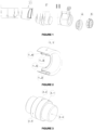
- the cup (1) comprised of five main parts, as detailed in Figure 2 , has: an external tab (1.1), an internal surface (1.2) of the external tab (1.1), an internal surface (1.3) of the internal tab, sealing element (1.4), and a pressure ring (1.5).
- the cup (1) is mechanically connected to the pipe between the external portion of the pipe (6.1) and the coating (3).
- cup (1) The purpose of the cup (1) is to mask the area of the pipe that will form the collar (cutback) and protect the bevel during the process of coating and transport. Its material may be metallic, polymeric, or composite.
- the co-polymeric adhesive used in the pipe coating process must adhere to the external surface of the external tab (1.1), and the internal diameter of the external tab must be approximately equal to the external diameter of the pipe, with tolerance that allows it to be slotted in by intervention, so that it can be positioned without free movement during the coating process.
- the internal surface (1.3) of the internal tab has a sealing element (1.4) formed of one or more rings of polymeric or rubber material, preferentially neoprene, to prevent water from entering its interior during the cooling process.
- the length of the external tab (1.1) varies from 100 to 200 mm, and the length of the internal tab varies from 50 to 200 mm, and the thickness of the wall of the cup (1) is less than or equal to 3 mm.
- the pressure ring (1.5) is made of metal or composite material, and it has a device to pressure the sealing element (1.4) against the internal wall of the pipe in order to ensure sealing during the cooling process and for its entire useful life.
- the pressure ring (1.5) also serves as a stopper for the cap (5) shown in Figure 6 .
- the function of the spacer (2), shown in Figure 3 , made of cast metal material, folded or welded, is to maintain adequate spacing and alignment between the pipes during coating. Its external diameter (2.1) is equal to the external diameter of the pipe to be coated, with tolerance ofupto ⁇ 10 mm.
- the spacer (2) is hollow (2.4) so that it is light, easy to manipulate, and to allow cooling water to enter into the pipe.
- the purpose of the coating (3) shown in Figure 4 is to protect the collar (cutback), adhering to the external surface of the cup (1), and its envelope (3.1) will be folded (3.2) at an angle varying from 90°C to 180°C in order to prevent it from opening after removal of the spacer.
- the purpose of the external ring (4) shown in Figure 5 used after removal of the spacer (2), is to affix the folded coating (3.2), creating a tab to protect the bevel (4.2). Its external diameter (4.5) is variable so that it can be slotted in by intervention in the infernal diameter of the cup (1).
- the purpose of the cap (5) shown in Figure 6 is to protect the inside of the pipe, and it is slotted into the component (1.5) of the cup (1). It is made of polymeric material or from a metal/polymer combination.
- the cap (5) has a safety relief valve (5.1), made of tin or stainless Steel, attached to the surface of the cap (4) by a screw or intervention, and it is used for the pressure range seeking to alleviate the pressure inside the pipe when necessary.
- the external diameter (5.2) of the cap is equal to the infernal diameter of the cup (1), and the mentioned cap also has a sealing system (5.3) to impede entry of any external means of oxidation, and furthermore, it has a handle (5.4) with a system to rapidly open and close the cap when necessary.
- the pipes are sent for use in the field, and the coating is cut by automation at an angle of less than 30°C, so that the system is removed quickly and precisely, either manually or by automation.
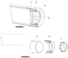
- Figure 7 shows a view of the system to protect coated pipes for on-land and subsea pipelines assembled at the end of the assembly process, and Figure 7 shows the mentioned system in an exploded perspective of the pipe after cutting and removing it.
- Figure 8 details the pipe (6.1) prepared to be coupled and welded in the field or on the vessel after the coating is cut, and the entire assembly (6.2) relative to the pipe protection system is removed from the pipe after cutting and removing the cap (5).
Landscapes
- Engineering & Computer Science (AREA)
- General Engineering & Computer Science (AREA)
- Mechanical Engineering (AREA)
- Manufacturing & Machinery (AREA)
- Protection Of Pipes Against Damage, Friction, And Corrosion (AREA)
Claims (11)
- Système de préservation de tubes utilisés pour conduits terrestres et/ou sous-marins, le système comprenant un tube (6.1), un revêtement (3) et un manchon (1) ; le tube comprenant une portion interne et une portion externe ; dans lequel la portion externe du tube est revêtue par ledit revêtement (3), et dans lequel le manchon (1) est relié mécaniquement au tube entre la portion externe du tube (6.1) et le revêtement (3), dans lequel le manchon (1) comprend en outre une languette externe (1.1), une surface interne (1.2) de la languette externe (1.1), une languette interne et une surface interne (1.3) de la languette interne ;dans lequel la surface interne (1.3) de la languette interne du manchon (1) est reliée mécaniquement à la portion interne du tube et une surface externe de la languette externe (1.1) du manchon (1) est reliée mécaniquement au revêtement (3) ;dans lequel la surface interne (1.3) de la languette interne est reliée à la languette externe (1.1) dans une partie de la liaison sous forme de U, comme un espace adjacent entre celles-ci ;dans lequel le tube est positionné entre la surface interne (1.2) de la languette externe (1.1) et la surface interne (1.3) de la languette interne, dans lequel le système comprend en outre : une bague externe (4) ;caractérisé en ce que le revêtement (3) recouvre la languette externe (1.1) du manchon (1) et est partiellement replié sur la languette interne ;dans lequel la bague externe (4) est configurée pour fixer la portion du revêtement replié sur la languette interne du manchon (1).
- Système selon la revendication 1, dans lequel le manchon (1) est réalisé en matériau métallique, polymérique ou composite.
- Système selon l'une quelconque des revendications 1 à 2, dans lequel le manchon (1) comprend un élément de scellage (1.4), de préférence constitué d'une ou plusieurs bagues réalisées en matériau polymérique ou en caoutchouc, de préférence en néoprène, sur une extrémité de la surface interne (1.3) de la languette interne.
- Système selon la revendication 1, dans lequel le système comprend en outre un couvercle (5), de préférence dans lequel le couvercle (5) est réalisé en matériau polymérique ou en une combinaison de métal/polymère ;- le couvercle étant relié mécaniquement à la bague externe (4) et au manchon (1) ;dans lequel le couvercle (5) est configuré pour sceller la portion interne du tube.
- Système selon la revendication 4, dans lequel le manchon (1) comprend une bague de pression (1.5), agissant comme une pièce d'arrêt entre le couvercle (5) et le manchon (1).
- Système selon l'une quelconque des revendications 4 à 5, dans lequel le couvercle (5) comprend une soupape de sécurité (5.1) pour relâcher la pression de l'intérieur du tube.
- Système selon l'une quelconque des revendications 1 à 6, dans lequel le système comprend en outre : un élément d'espacement (2), de préférence dans lequel l'élément d'espacement (2) est réalisé en matériau métallique coulé, replié ou soudé ;
dans lequel l'élément d'espacement (2) relie mécaniquement, en alignant deux tubes consécutifs dans une ligne de production et/ou stockage, avec un espacement approprié entre les tubes pour permettre une position de coupe appropriée par rapport au pliage de l'enveloppe du revêtement (3). - Procédé de préservation de tubes pour conduits terrestres et sous-marins, le tube comprenant une portion interne et une portion externe, dans lequel le procédé comprend fournir le système selon l'une quelconque des revendications 1 à 7 et comprend les étapes suivantesa) fixation d'un manchon de protection (1) à l'extrémité du tube (6.1) ;b) application d'un revêtement (3) au tube (6.1), de préférence dans lequel l'étape b) est réalisée par extrusion de polymères, plus de préférence dans lequel le polymère est du polyéthylène ou du polypropylène ;c) découpe du revêtement (3) ;d) pliage de l'enveloppe de revêtement (3.1) sur le manchon (1), de préférence dans lequel l'étape d) est réalisée par le biais du pliage de l'enveloppe de revêtement (3.1) à un angle de 90 à 180°C sur le manchon ;e) fixation d'une bague externe (4) au manchon (1) et à la partie repliée du revêtement sur le manchon (1) ; etf) fixation d'un couvercle (5) à la bague externe (4).
- Procédé selon la revendication 8, dont le procédé comprend en outre une ou plusieurs des étapes supplémentaires suivantes :- nettoyage du tube 6.1, avant l'étape a) ;- préchauffage, après l'étape de nettoyage de tube et avant l'étape a, de préférence dans lequel l'étape de préchauffage est réalisée à 3°C au-dessus de la température du point de rosée et à moins de 100°C ;- sablage, après l'étape de nettoyage et/ou préchauffage, et avant l'étape a), de préférence dans lequel l'étape de sablage est réalisée en deux sous-étapes, dans lequel la première sous-étape permet un nettoyage de surface, et la deuxième sous-étape crée un profil de rugosité dans l'extrémité du tube qui est compris entre 60 et 100 pm, plus de préférence dans lequel dans la première sous-étape on utilise un grain rond ou un mélange de grain rond et angulaire, et dans la deuxième sous-étape on utilise uniquement du grain angulaire ;- découpe du revêtement (3) avant l'étape d) ;- refroidissement après l'étape d) ;- séchage interne du tube (6.1) avant l'étape f.
- Procédé selon l'une quelconque des revendications 8-9, dans lequel le procédé comprend une étape supplémentaire de couplage et alignement de plusieurs tubes (6.1).
- Procédé selon l'une quelconque des revendications 8-10, dans lequel le procédé comprend une étape supplémentaire de chauffage des tubes (6.1) à entre 200°C et 275°C, et/ou dans lequel le comprend une étape supplémentaire d'application d'une résine au tube (6.1), de préférence dans lequel l'étape de chauffage des tubes est réalisée par induction électromagnétique, plus de préférence dans lequel, l'étape de chauffage des tubes (6.1) est réalisée par induction électromagnétique et le tube (6.1) est polarisé avec une polarité qui est l'inverse de celle de la résine.
Applications Claiming Priority (2)
| Application Number | Priority Date | Filing Date | Title |
|---|---|---|---|
| BR102019015918-9A BR102019015918B1 (pt) | 2019-07-31 | Sistema de preservação de tubos revestidos para dutos terrestres e submarinos e método de preservação de tubos | |
| PCT/BR2020/050283 WO2021016691A1 (fr) | 2019-07-31 | 2020-07-23 | Système de préservation de tubes revêtus pour conduits terrestres et sous-marins, et procédé de préservation de tubes |
Publications (3)
| Publication Number | Publication Date |
|---|---|
| EP4006401A1 EP4006401A1 (fr) | 2022-06-01 |
| EP4006401A4 EP4006401A4 (fr) | 2023-08-09 |
| EP4006401B1 true EP4006401B1 (fr) | 2025-03-05 |
Family
ID=74228179
Family Applications (1)
| Application Number | Title | Priority Date | Filing Date |
|---|---|---|---|
| EP20848533.4A Active EP4006401B1 (fr) | 2019-07-31 | 2020-07-23 | Système de préservation de tubes revêtus pour conduits terrestres et sous-marins, et procédé de préservation de tubes |
Country Status (8)
| Country | Link |
|---|---|
| US (2) | US12055262B2 (fr) |
| EP (1) | EP4006401B1 (fr) |
| CN (1) | CN114585850B (fr) |
| AR (1) | AR119517A1 (fr) |
| AU (1) | AU2020322418B2 (fr) |
| CA (1) | CA3148232A1 (fr) |
| NO (1) | NO20220141A1 (fr) |
| WO (1) | WO2021016691A1 (fr) |
Families Citing this family (1)
| Publication number | Priority date | Publication date | Assignee | Title |
|---|---|---|---|---|
| CN119748486B (zh) * | 2025-03-07 | 2025-05-27 | 豪森润博智能装备常州有限公司 | 一种用于汽车核心零部件生产的人形机器人组装装配工艺及设备 |
Family Cites Families (24)
| Publication number | Priority date | Publication date | Assignee | Title |
|---|---|---|---|---|
| US199349A (en) * | 1878-01-22 | Improvement in hose-couplings | ||
| US1165427A (en) * | 1915-03-04 | 1915-12-28 | Enameled Metals Company | Protector for pipes or conduit units. |
| US1758613A (en) * | 1927-11-25 | 1930-05-13 | Clayton Mark & Company | Thread protector for pipes |
| US2022189A (en) * | 1935-03-29 | 1935-11-26 | Engstrom Birger | Pipe thread protector |
| US3157549A (en) * | 1961-10-30 | 1964-11-17 | Clifford F Morain | Methods of protecting lengths of metal pipe |
| US3403206A (en) * | 1965-06-24 | 1968-09-24 | Johns Manville | Method for forming a fluid conduit |
| US3744528A (en) | 1971-04-26 | 1973-07-10 | S & V Plastics Inc | Tube closure member |
| JPS5244425B2 (fr) | 1973-11-06 | 1977-11-08 | ||
| US4429719A (en) * | 1982-08-05 | 1984-02-07 | Mosing Donald E | Pipe thread protector |
| US5720834A (en) | 1992-05-04 | 1998-02-24 | Shaw Industries Ltd. | Method for covering a pipeline by wrapping |
| US7487801B2 (en) | 2006-10-24 | 2009-02-10 | Protective Industries, Inc. | Cap and plug for masking or shipping |
| EP2102541A1 (fr) * | 2006-11-20 | 2009-09-23 | Dytech - Dynamic Fluid Technologies S.P.A. | Tuyau souple ayant un assemblage simplifié |
| JP5244425B2 (ja) | 2008-03-06 | 2013-07-24 | 日本ポリプロ株式会社 | プロピレン系表面保護用フィルム |
| DE102009017975A1 (de) | 2008-12-23 | 2010-07-08 | Rosen Swiss Ag | Sicherheitsvorrichtung und System zur Überwachung von Rohren |
| DE102010046542A1 (de) * | 2010-09-27 | 2012-03-29 | Putzmeister Engineering Gmbh | Förderrohr sowie Verfahren zur Herstellung eines Förderrohrs |
| DE202011103302U1 (de) * | 2011-06-30 | 2011-11-09 | Rosen Swiss Ag | Sicherheitskappe für Pipelinerohre |
| GB2501491B (en) * | 2012-04-24 | 2014-10-15 | Acergy France Sa | Techniques for protecting pipe coatings |
| FR2998639B1 (fr) * | 2012-11-26 | 2014-11-28 | Vallourec Mannesmann Oil & Gas | Dispositif de protection d'une extremite male d'un composant de joint filete tubulaire a joint souple |
| JP6172963B2 (ja) | 2013-02-14 | 2017-08-02 | 株式会社藤井合金製作所 | 保護キャップ |
| FR3030676A1 (fr) * | 2014-12-23 | 2016-06-24 | Vallourec Oil & Gas France | Dispositif de protection d'une extremite d'un composant de joint filete tubulaire a joint souple |
| DE102015102404A1 (de) * | 2015-02-20 | 2016-08-25 | Viega Gmbh & Co. Kg | Fitting mit Beschichtung, Rohrleitungssystem und Verwendung des Fittings oder des Rohrleitungssystems |
| EP3239584A1 (fr) * | 2016-04-28 | 2017-11-01 | 3M Innovative Properties Company | Méthode pour étanchéifier une canalisation |
| RU178318U1 (ru) | 2017-06-01 | 2018-03-29 | Акционерное общество "Выксунский металлургический завод" (АО "ВМЗ") | Заглушка защитная для труб |
| RU2659010C1 (ru) | 2017-09-19 | 2018-06-26 | Общество с ограниченной ответственностью "Мехсервис" | Полимерная торцевая заглушка, способ ее производства, способ защиты полого цилиндрического изделия и изделие с установленной заглушкой |
-
2020
- 2020-07-23 AU AU2020322418A patent/AU2020322418B2/en active Active
- 2020-07-23 WO PCT/BR2020/050283 patent/WO2021016691A1/fr not_active Ceased
- 2020-07-23 CN CN202080069021.2A patent/CN114585850B/zh active Active
- 2020-07-23 NO NO20220141A patent/NO20220141A1/en unknown
- 2020-07-23 US US17/628,592 patent/US12055262B2/en active Active
- 2020-07-23 EP EP20848533.4A patent/EP4006401B1/fr active Active
- 2020-07-23 CA CA3148232A patent/CA3148232A1/fr active Pending
- 2020-07-29 AR ARP200102127A patent/AR119517A1/es unknown
-
2024
- 2024-02-02 US US18/431,123 patent/US12203583B2/en active Active
Also Published As
| Publication number | Publication date |
|---|---|
| EP4006401A4 (fr) | 2023-08-09 |
| EP4006401A1 (fr) | 2022-06-01 |
| US12055262B2 (en) | 2024-08-06 |
| WO2021016691A1 (fr) | 2021-02-04 |
| NO20220141A1 (en) | 2022-01-28 |
| CA3148232A1 (fr) | 2021-02-04 |
| AU2020322418A1 (en) | 2022-03-10 |
| BR102019015918A2 (pt) | 2021-02-09 |
| US20220252203A1 (en) | 2022-08-11 |
| US20240175536A1 (en) | 2024-05-30 |
| CN114585850A (zh) | 2022-06-03 |
| AU2020322418B2 (en) | 2026-04-23 |
| US12203583B2 (en) | 2025-01-21 |
| AR119517A1 (es) | 2021-12-22 |
| CN114585850B (zh) | 2024-06-18 |
Similar Documents
| Publication | Publication Date | Title |
|---|---|---|
| CN103328872B (zh) | 构造碳氢化合物管线且尤其是水下管线的管道连接方法 | |
| US12203583B2 (en) | System for protecting coated pipes for on-land and subsea pipelines and the method for protecting pipes | |
| JP2010518329A (ja) | パイプおよびブロック断熱のための事前適用される保護被覆構造 | |
| US9611971B2 (en) | Device for protecting a male end of a component of a flexible-joint threaded tubular connection | |
| US5219187A (en) | Pipe connection | |
| US20090313794A1 (en) | Method and apparatus for mounting distributed buoyancy modules on a rigid pipeline | |
| US20180274711A1 (en) | Protector for threaded end of a tubular component with flexible seal | |
| RU2816005C2 (ru) | Система для защиты покрытых труб для наземных и подводных трубопроводов и способ защиты труб | |
| US20070240780A1 (en) | Adhesion promoting end treatment system and method for girth-welds | |
| EP3287683B1 (fr) | Techniques de protection de revêtements de tuyau | |
| US20070240816A1 (en) | Protective girth-weld cover with air release | |
| US6247499B1 (en) | Pipe wrap corrosion protection system | |
| CN110998164A (zh) | 由管或者管连接部构成的管装置 | |
| BR102019015918B1 (pt) | Sistema de preservação de tubos revestidos para dutos terrestres e submarinos e método de preservação de tubos | |
| BR112017007898B1 (pt) | Método para revestir junta de campo, seção de tubo para formar uma junta de campo e junta de campo revestida | |
| CN215215101U (zh) | 一种内壁涂塑海水管穿舱结构 | |
| CN114222882B (zh) | 管道、管状接头及对应的制造方法 | |
| US1165427A (en) | Protector for pipes or conduit units. | |
| Thomas et al. | 2-Layer Polyethylene Extruded Factory-Applied Pipe Corrosion Coating | |
| Filipe | ANTI-CORROSION PROTECTION FOR FIELD JOINT COATINGS IN OFFSHORE AND ONSHORE PIPELINES | |
| Thomas | 2-Layer Polyethylene Plant Applied Mainline Coating for Use in Water and Wastewater Pipeline Applications | |
| RU2236633C2 (ru) | Способ внутренней противокоррозионной защиты зоны сварного соединения труб и устройство для его выполнения | |
| JPH0375266B2 (fr) | ||
| JPH08166094A (ja) | 管端防食コア | |
| Kehr | Preventing and Solving Delamination During Multilayer Pipeline Girth Weld Coating Application |
Legal Events
| Date | Code | Title | Description |
|---|---|---|---|
| STAA | Information on the status of an ep patent application or granted ep patent |
Free format text: STATUS: THE INTERNATIONAL PUBLICATION HAS BEEN MADE |
|
| PUAI | Public reference made under article 153(3) epc to a published international application that has entered the european phase |
Free format text: ORIGINAL CODE: 0009012 |
|
| STAA | Information on the status of an ep patent application or granted ep patent |
Free format text: STATUS: REQUEST FOR EXAMINATION WAS MADE |
|
| 17P | Request for examination filed |
Effective date: 20220222 |
|
| AK | Designated contracting states |
Kind code of ref document: A1 Designated state(s): AL AT BE BG CH CY CZ DE DK EE ES FI FR GB GR HR HU IE IS IT LI LT LU LV MC MK MT NL NO PL PT RO RS SE SI SK SM TR |
|
| RAP3 | Party data changed (applicant data changed or rights of an application transferred) |
Owner name: IPT INSTITUTO DE PESQUISAS TECNOLOGICAS DO EST.S.PAULO S/A Owner name: PETROLEO BRASILEIRO S.A. - PETROBRAS |
|
| DAV | Request for validation of the european patent (deleted) | ||
| DAX | Request for extension of the european patent (deleted) | ||
| REG | Reference to a national code |
Ref legal event code: R079 Ipc: F16L0057000000 Ref country code: DE Ref legal event code: R079 Ref document number: 602020047364 Country of ref document: DE Free format text: PREVIOUS MAIN CLASS: F16L0055115000 Ipc: F16L0057000000 |
|
| A4 | Supplementary search report drawn up and despatched |
Effective date: 20230712 |
|
| RIC1 | Information provided on ipc code assigned before grant |
Ipc: F16L 13/02 20060101ALN20230706BHEP Ipc: B65D 59/06 20060101ALI20230706BHEP Ipc: B65D 59/02 20060101ALI20230706BHEP Ipc: B29C 63/34 20060101ALI20230706BHEP Ipc: B29C 63/18 20060101ALI20230706BHEP Ipc: B65D 59/00 20060101ALI20230706BHEP Ipc: F16L 58/10 20060101ALI20230706BHEP Ipc: F16L 55/11 20060101ALI20230706BHEP Ipc: F16L 57/00 20060101AFI20230706BHEP |
|
| P01 | Opt-out of the competence of the unified patent court (upc) registered |
Effective date: 20231212 |
|
| GRAP | Despatch of communication of intention to grant a patent |
Free format text: ORIGINAL CODE: EPIDOSNIGR1 |
|
| STAA | Information on the status of an ep patent application or granted ep patent |
Free format text: STATUS: GRANT OF PATENT IS INTENDED |
|
| RIC1 | Information provided on ipc code assigned before grant |
Ipc: F16L 13/02 20060101ALN20241009BHEP Ipc: B65D 59/06 20060101ALI20241009BHEP Ipc: B65D 59/02 20060101ALI20241009BHEP Ipc: B29C 63/34 20060101ALI20241009BHEP Ipc: B29C 63/18 20060101ALI20241009BHEP Ipc: B65D 59/00 20060101ALI20241009BHEP Ipc: F16L 58/10 20060101ALI20241009BHEP Ipc: F16L 55/11 20060101ALI20241009BHEP Ipc: F16L 57/00 20060101AFI20241009BHEP |
|
| RIC1 | Information provided on ipc code assigned before grant |
Ipc: F16L 13/02 20060101ALN20241011BHEP Ipc: B65D 59/06 20060101ALI20241011BHEP Ipc: B65D 59/02 20060101ALI20241011BHEP Ipc: B29C 63/34 20060101ALI20241011BHEP Ipc: B29C 63/18 20060101ALI20241011BHEP Ipc: B65D 59/00 20060101ALI20241011BHEP Ipc: F16L 58/10 20060101ALI20241011BHEP Ipc: F16L 55/11 20060101ALI20241011BHEP Ipc: F16L 57/00 20060101AFI20241011BHEP |
|
| INTG | Intention to grant announced |
Effective date: 20241023 |
|
| GRAS | Grant fee paid |
Free format text: ORIGINAL CODE: EPIDOSNIGR3 |
|
| GRAA | (expected) grant |
Free format text: ORIGINAL CODE: 0009210 |
|
| STAA | Information on the status of an ep patent application or granted ep patent |
Free format text: STATUS: THE PATENT HAS BEEN GRANTED |
|
| AK | Designated contracting states |
Kind code of ref document: B1 Designated state(s): AL AT BE BG CH CY CZ DE DK EE ES FI FR GB GR HR HU IE IS IT LI LT LU LV MC MK MT NL NO PL PT RO RS SE SI SK SM TR |
|
| REG | Reference to a national code |
Ref country code: GB Ref legal event code: FG4D |
|
| REG | Reference to a national code |
Ref country code: CH Ref legal event code: EP |
|
| REG | Reference to a national code |
Ref country code: DE Ref legal event code: R096 Ref document number: 602020047364 Country of ref document: DE |
|
| REG | Reference to a national code |
Ref country code: IE Ref legal event code: FG4D |
|
| REG | Reference to a national code |
Ref country code: NL Ref legal event code: FP |
|
| PG25 | Lapsed in a contracting state [announced via postgrant information from national office to epo] |
Ref country code: RS Free format text: LAPSE BECAUSE OF FAILURE TO SUBMIT A TRANSLATION OF THE DESCRIPTION OR TO PAY THE FEE WITHIN THE PRESCRIBED TIME-LIMIT Effective date: 20250605 |
|
| PG25 | Lapsed in a contracting state [announced via postgrant information from national office to epo] |
Ref country code: FI Free format text: LAPSE BECAUSE OF FAILURE TO SUBMIT A TRANSLATION OF THE DESCRIPTION OR TO PAY THE FEE WITHIN THE PRESCRIBED TIME-LIMIT Effective date: 20250305 |
|
| PG25 | Lapsed in a contracting state [announced via postgrant information from national office to epo] |
Ref country code: ES Free format text: LAPSE BECAUSE OF FAILURE TO SUBMIT A TRANSLATION OF THE DESCRIPTION OR TO PAY THE FEE WITHIN THE PRESCRIBED TIME-LIMIT Effective date: 20250305 |
|
| REG | Reference to a national code |
Ref country code: LT Ref legal event code: MG9D |
|
| PG25 | Lapsed in a contracting state [announced via postgrant information from national office to epo] |
Ref country code: NO Free format text: LAPSE BECAUSE OF FAILURE TO SUBMIT A TRANSLATION OF THE DESCRIPTION OR TO PAY THE FEE WITHIN THE PRESCRIBED TIME-LIMIT Effective date: 20250605 |
|
| PG25 | Lapsed in a contracting state [announced via postgrant information from national office to epo] |
Ref country code: HR Free format text: LAPSE BECAUSE OF FAILURE TO SUBMIT A TRANSLATION OF THE DESCRIPTION OR TO PAY THE FEE WITHIN THE PRESCRIBED TIME-LIMIT Effective date: 20250305 |
|
| PG25 | Lapsed in a contracting state [announced via postgrant information from national office to epo] |
Ref country code: LV Free format text: LAPSE BECAUSE OF FAILURE TO SUBMIT A TRANSLATION OF THE DESCRIPTION OR TO PAY THE FEE WITHIN THE PRESCRIBED TIME-LIMIT Effective date: 20250305 |
|
| PG25 | Lapsed in a contracting state [announced via postgrant information from national office to epo] |
Ref country code: GR Free format text: LAPSE BECAUSE OF FAILURE TO SUBMIT A TRANSLATION OF THE DESCRIPTION OR TO PAY THE FEE WITHIN THE PRESCRIBED TIME-LIMIT Effective date: 20250606 Ref country code: BG Free format text: LAPSE BECAUSE OF FAILURE TO SUBMIT A TRANSLATION OF THE DESCRIPTION OR TO PAY THE FEE WITHIN THE PRESCRIBED TIME-LIMIT Effective date: 20250305 |
|
| REG | Reference to a national code |
Ref country code: AT Ref legal event code: MK05 Ref document number: 1773195 Country of ref document: AT Kind code of ref document: T Effective date: 20250305 |
|
| PGFP | Annual fee paid to national office [announced via postgrant information from national office to epo] |
Ref country code: NL Payment date: 20250704 Year of fee payment: 6 |
|
| PG25 | Lapsed in a contracting state [announced via postgrant information from national office to epo] |
Ref country code: SE Free format text: LAPSE BECAUSE OF FAILURE TO SUBMIT A TRANSLATION OF THE DESCRIPTION OR TO PAY THE FEE WITHIN THE PRESCRIBED TIME-LIMIT Effective date: 20250305 |
|
| PG25 | Lapsed in a contracting state [announced via postgrant information from national office to epo] |
Ref country code: SM Free format text: LAPSE BECAUSE OF FAILURE TO SUBMIT A TRANSLATION OF THE DESCRIPTION OR TO PAY THE FEE WITHIN THE PRESCRIBED TIME-LIMIT Effective date: 20250305 |
|
| PG25 | Lapsed in a contracting state [announced via postgrant information from national office to epo] |
Ref country code: PT Free format text: LAPSE BECAUSE OF FAILURE TO SUBMIT A TRANSLATION OF THE DESCRIPTION OR TO PAY THE FEE WITHIN THE PRESCRIBED TIME-LIMIT Effective date: 20250707 |
|
| PG25 | Lapsed in a contracting state [announced via postgrant information from national office to epo] |
Ref country code: IT Free format text: LAPSE BECAUSE OF FAILURE TO SUBMIT A TRANSLATION OF THE DESCRIPTION OR TO PAY THE FEE WITHIN THE PRESCRIBED TIME-LIMIT Effective date: 20250305 Ref country code: PL Free format text: LAPSE BECAUSE OF FAILURE TO SUBMIT A TRANSLATION OF THE DESCRIPTION OR TO PAY THE FEE WITHIN THE PRESCRIBED TIME-LIMIT Effective date: 20250305 |
|
| PG25 | Lapsed in a contracting state [announced via postgrant information from national office to epo] |
Ref country code: AT Free format text: LAPSE BECAUSE OF FAILURE TO SUBMIT A TRANSLATION OF THE DESCRIPTION OR TO PAY THE FEE WITHIN THE PRESCRIBED TIME-LIMIT Effective date: 20250305 |
|
| PG25 | Lapsed in a contracting state [announced via postgrant information from national office to epo] |
Ref country code: CZ Free format text: LAPSE BECAUSE OF FAILURE TO SUBMIT A TRANSLATION OF THE DESCRIPTION OR TO PAY THE FEE WITHIN THE PRESCRIBED TIME-LIMIT Effective date: 20250305 Ref country code: EE Free format text: LAPSE BECAUSE OF FAILURE TO SUBMIT A TRANSLATION OF THE DESCRIPTION OR TO PAY THE FEE WITHIN THE PRESCRIBED TIME-LIMIT Effective date: 20250305 |
|
| PG25 | Lapsed in a contracting state [announced via postgrant information from national office to epo] |
Ref country code: RO Free format text: LAPSE BECAUSE OF FAILURE TO SUBMIT A TRANSLATION OF THE DESCRIPTION OR TO PAY THE FEE WITHIN THE PRESCRIBED TIME-LIMIT Effective date: 20250305 |
|
| PG25 | Lapsed in a contracting state [announced via postgrant information from national office to epo] |
Ref country code: SK Free format text: LAPSE BECAUSE OF FAILURE TO SUBMIT A TRANSLATION OF THE DESCRIPTION OR TO PAY THE FEE WITHIN THE PRESCRIBED TIME-LIMIT Effective date: 20250305 |
|
| PG25 | Lapsed in a contracting state [announced via postgrant information from national office to epo] |
Ref country code: IS Free format text: LAPSE BECAUSE OF FAILURE TO SUBMIT A TRANSLATION OF THE DESCRIPTION OR TO PAY THE FEE WITHIN THE PRESCRIBED TIME-LIMIT Effective date: 20250705 |
|
| REG | Reference to a national code |
Ref country code: DE Ref legal event code: R097 Ref document number: 602020047364 Country of ref document: DE |
|
| PLBE | No opposition filed within time limit |
Free format text: ORIGINAL CODE: 0009261 |
|
| STAA | Information on the status of an ep patent application or granted ep patent |
Free format text: STATUS: NO OPPOSITION FILED WITHIN TIME LIMIT |
|
| PG25 | Lapsed in a contracting state [announced via postgrant information from national office to epo] |
Ref country code: DK Free format text: LAPSE BECAUSE OF FAILURE TO SUBMIT A TRANSLATION OF THE DESCRIPTION OR TO PAY THE FEE WITHIN THE PRESCRIBED TIME-LIMIT Effective date: 20250305 |
|
| REG | Reference to a national code |
Ref country code: CH Ref legal event code: L10 Free format text: ST27 STATUS EVENT CODE: U-0-0-L10-L00 (AS PROVIDED BY THE NATIONAL OFFICE) Effective date: 20260114 |
|
| REG | Reference to a national code |
Ref country code: DE Ref legal event code: R119 Ref document number: 602020047364 Country of ref document: DE |
|
| 26N | No opposition filed |
Effective date: 20251208 |
|
| REG | Reference to a national code |
Ref country code: CH Ref legal event code: H13 Free format text: ST27 STATUS EVENT CODE: U-0-0-H10-H13 (AS PROVIDED BY THE NATIONAL OFFICE) Effective date: 20260224 |
|
| PG25 | Lapsed in a contracting state [announced via postgrant information from national office to epo] |
Ref country code: LU Free format text: LAPSE BECAUSE OF NON-PAYMENT OF DUE FEES Effective date: 20250723 |
|
| GBPC | Gb: european patent ceased through non-payment of renewal fee |
Effective date: 20250723 |
|
| REG | Reference to a national code |
Ref country code: BE Ref legal event code: MM Effective date: 20250731 |
|
| PG25 | Lapsed in a contracting state [announced via postgrant information from national office to epo] |
Ref country code: GB Free format text: LAPSE BECAUSE OF NON-PAYMENT OF DUE FEES Effective date: 20250723 |
|
| PG25 | Lapsed in a contracting state [announced via postgrant information from national office to epo] |
Ref country code: DE Free format text: LAPSE BECAUSE OF NON-PAYMENT OF DUE FEES Effective date: 20260203 |
|
| PG25 | Lapsed in a contracting state [announced via postgrant information from national office to epo] |
Ref country code: BE Free format text: LAPSE BECAUSE OF NON-PAYMENT OF DUE FEES Effective date: 20250731 |
|
| PG25 | Lapsed in a contracting state [announced via postgrant information from national office to epo] |
Ref country code: FR Free format text: LAPSE BECAUSE OF NON-PAYMENT OF DUE FEES Effective date: 20250731 |