EP4006409B1 - Dispositif d'éclairage de véhicule, dispositif de projection de lumière invisible de véhicule, et dispositif de détection d'objet cible - Google Patents
Dispositif d'éclairage de véhicule, dispositif de projection de lumière invisible de véhicule, et dispositif de détection d'objet cible Download PDFInfo
- Publication number
- EP4006409B1 EP4006409B1 EP20894534.5A EP20894534A EP4006409B1 EP 4006409 B1 EP4006409 B1 EP 4006409B1 EP 20894534 A EP20894534 A EP 20894534A EP 4006409 B1 EP4006409 B1 EP 4006409B1
- Authority
- EP
- European Patent Office
- Prior art keywords
- light
- invisible
- emitting units
- vehicle
- emitting
- Prior art date
- Legal status (The legal status is an assumption and is not a legal conclusion. Google has not performed a legal analysis and makes no representation as to the accuracy of the status listed.)
- Active
Links
Images







Classifications
-
- B—PERFORMING OPERATIONS; TRANSPORTING
- B60—VEHICLES IN GENERAL
- B60Q—ARRANGEMENT OF SIGNALLING OR LIGHTING DEVICES, THE MOUNTING OR SUPPORTING THEREOF OR CIRCUITS THEREFOR, FOR VEHICLES IN GENERAL
- B60Q1/00—Arrangement of optical signalling or lighting devices, the mounting or supporting thereof or circuits therefor
- B60Q1/02—Arrangement of optical signalling or lighting devices, the mounting or supporting thereof or circuits therefor the devices being primarily intended to illuminate the way ahead or to illuminate other areas of way or environments
- B60Q1/04—Arrangement of optical signalling or lighting devices, the mounting or supporting thereof or circuits therefor the devices being primarily intended to illuminate the way ahead or to illuminate other areas of way or environments the devices being headlights
- B60Q1/06—Arrangement of optical signalling or lighting devices, the mounting or supporting thereof or circuits therefor the devices being primarily intended to illuminate the way ahead or to illuminate other areas of way or environments the devices being headlights adjustable, e.g. remotely-controlled from inside vehicle
-
- B—PERFORMING OPERATIONS; TRANSPORTING
- B60—VEHICLES IN GENERAL
- B60R—VEHICLES, VEHICLE FITTINGS, OR VEHICLE PARTS, NOT OTHERWISE PROVIDED FOR
- B60R21/00—Arrangements or fittings on vehicles for protecting or preventing injuries to occupants or pedestrians in case of accidents or other traffic risks
- B60R21/01—Electrical circuits for triggering passive safety arrangements, e.g. airbags, safety belt tighteners, in case of vehicle accidents or impending vehicle accidents
- B60R21/013—Electrical circuits for triggering passive safety arrangements, e.g. airbags, safety belt tighteners, in case of vehicle accidents or impending vehicle accidents including means for detecting collisions, impending collisions or roll-over
- B60R21/0134—Electrical circuits for triggering passive safety arrangements, e.g. airbags, safety belt tighteners, in case of vehicle accidents or impending vehicle accidents including means for detecting collisions, impending collisions or roll-over responsive to imminent contact with an obstacle, e.g. using radar systems
-
- F—MECHANICAL ENGINEERING; LIGHTING; HEATING; WEAPONS; BLASTING
- F21—LIGHTING
- F21S—NON-PORTABLE LIGHTING DEVICES; SYSTEMS THEREOF; VEHICLE LIGHTING DEVICES SPECIALLY ADAPTED FOR VEHICLE EXTERIORS
- F21S41/00—Illuminating devices specially adapted for vehicle exteriors, e.g. headlamps
- F21S41/10—Illuminating devices specially adapted for vehicle exteriors, e.g. headlamps characterised by the light source
- F21S41/14—Illuminating devices specially adapted for vehicle exteriors, e.g. headlamps characterised by the light source characterised by the type of light source
- F21S41/141—Light emitting diodes [LED]
- F21S41/143—Light emitting diodes [LED] the main emission direction of the LED being parallel to the optical axis of the illuminating device
-
- F—MECHANICAL ENGINEERING; LIGHTING; HEATING; WEAPONS; BLASTING
- F21—LIGHTING
- F21S—NON-PORTABLE LIGHTING DEVICES; SYSTEMS THEREOF; VEHICLE LIGHTING DEVICES SPECIALLY ADAPTED FOR VEHICLE EXTERIORS
- F21S41/00—Illuminating devices specially adapted for vehicle exteriors, e.g. headlamps
- F21S41/10—Illuminating devices specially adapted for vehicle exteriors, e.g. headlamps characterised by the light source
- F21S41/14—Illuminating devices specially adapted for vehicle exteriors, e.g. headlamps characterised by the light source characterised by the type of light source
- F21S41/141—Light emitting diodes [LED]
- F21S41/151—Light emitting diodes [LED] arranged in one or more lines
-
- F—MECHANICAL ENGINEERING; LIGHTING; HEATING; WEAPONS; BLASTING
- F21—LIGHTING
- F21S—NON-PORTABLE LIGHTING DEVICES; SYSTEMS THEREOF; VEHICLE LIGHTING DEVICES SPECIALLY ADAPTED FOR VEHICLE EXTERIORS
- F21S41/00—Illuminating devices specially adapted for vehicle exteriors, e.g. headlamps
- F21S41/10—Illuminating devices specially adapted for vehicle exteriors, e.g. headlamps characterised by the light source
- F21S41/14—Illuminating devices specially adapted for vehicle exteriors, e.g. headlamps characterised by the light source characterised by the type of light source
- F21S41/16—Laser light sources
-
- F—MECHANICAL ENGINEERING; LIGHTING; HEATING; WEAPONS; BLASTING
- F21—LIGHTING
- F21S—NON-PORTABLE LIGHTING DEVICES; SYSTEMS THEREOF; VEHICLE LIGHTING DEVICES SPECIALLY ADAPTED FOR VEHICLE EXTERIORS
- F21S41/00—Illuminating devices specially adapted for vehicle exteriors, e.g. headlamps
- F21S41/10—Illuminating devices specially adapted for vehicle exteriors, e.g. headlamps characterised by the light source
- F21S41/19—Attachment of light sources or lamp holders
-
- F—MECHANICAL ENGINEERING; LIGHTING; HEATING; WEAPONS; BLASTING
- F21—LIGHTING
- F21S—NON-PORTABLE LIGHTING DEVICES; SYSTEMS THEREOF; VEHICLE LIGHTING DEVICES SPECIALLY ADAPTED FOR VEHICLE EXTERIORS
- F21S41/00—Illuminating devices specially adapted for vehicle exteriors, e.g. headlamps
- F21S41/10—Illuminating devices specially adapted for vehicle exteriors, e.g. headlamps characterised by the light source
- F21S41/19—Attachment of light sources or lamp holders
- F21S41/192—Details of lamp holders, terminals or connectors
-
- F—MECHANICAL ENGINEERING; LIGHTING; HEATING; WEAPONS; BLASTING
- F21—LIGHTING
- F21S—NON-PORTABLE LIGHTING DEVICES; SYSTEMS THEREOF; VEHICLE LIGHTING DEVICES SPECIALLY ADAPTED FOR VEHICLE EXTERIORS
- F21S41/00—Illuminating devices specially adapted for vehicle exteriors, e.g. headlamps
- F21S41/20—Illuminating devices specially adapted for vehicle exteriors, e.g. headlamps characterised by refractors, transparent cover plates, light guides or filters
- F21S41/25—Projection lenses
-
- F—MECHANICAL ENGINEERING; LIGHTING; HEATING; WEAPONS; BLASTING
- F21—LIGHTING
- F21S—NON-PORTABLE LIGHTING DEVICES; SYSTEMS THEREOF; VEHICLE LIGHTING DEVICES SPECIALLY ADAPTED FOR VEHICLE EXTERIORS
- F21S41/00—Illuminating devices specially adapted for vehicle exteriors, e.g. headlamps
- F21S41/20—Illuminating devices specially adapted for vehicle exteriors, e.g. headlamps characterised by refractors, transparent cover plates, light guides or filters
- F21S41/25—Projection lenses
- F21S41/255—Lenses with a front view of circular or truncated circular outline
-
- F—MECHANICAL ENGINEERING; LIGHTING; HEATING; WEAPONS; BLASTING
- F21—LIGHTING
- F21S—NON-PORTABLE LIGHTING DEVICES; SYSTEMS THEREOF; VEHICLE LIGHTING DEVICES SPECIALLY ADAPTED FOR VEHICLE EXTERIORS
- F21S41/00—Illuminating devices specially adapted for vehicle exteriors, e.g. headlamps
- F21S41/20—Illuminating devices specially adapted for vehicle exteriors, e.g. headlamps characterised by refractors, transparent cover plates, light guides or filters
- F21S41/285—Refractors, transparent cover plates, light guides or filters not provided in groups F21S41/24 - F21S41/2805
-
- F—MECHANICAL ENGINEERING; LIGHTING; HEATING; WEAPONS; BLASTING
- F21—LIGHTING
- F21S—NON-PORTABLE LIGHTING DEVICES; SYSTEMS THEREOF; VEHICLE LIGHTING DEVICES SPECIALLY ADAPTED FOR VEHICLE EXTERIORS
- F21S41/00—Illuminating devices specially adapted for vehicle exteriors, e.g. headlamps
- F21S41/30—Illuminating devices specially adapted for vehicle exteriors, e.g. headlamps characterised by reflectors
- F21S41/32—Optical layout thereof
- F21S41/321—Optical layout thereof the reflector being a surface of revolution or a planar surface, e.g. truncated
-
- F—MECHANICAL ENGINEERING; LIGHTING; HEATING; WEAPONS; BLASTING
- F21—LIGHTING
- F21S—NON-PORTABLE LIGHTING DEVICES; SYSTEMS THEREOF; VEHICLE LIGHTING DEVICES SPECIALLY ADAPTED FOR VEHICLE EXTERIORS
- F21S41/00—Illuminating devices specially adapted for vehicle exteriors, e.g. headlamps
- F21S41/30—Illuminating devices specially adapted for vehicle exteriors, e.g. headlamps characterised by reflectors
- F21S41/32—Optical layout thereof
- F21S41/322—Optical layout thereof the reflector using total internal reflection
-
- F—MECHANICAL ENGINEERING; LIGHTING; HEATING; WEAPONS; BLASTING
- F21—LIGHTING
- F21S—NON-PORTABLE LIGHTING DEVICES; SYSTEMS THEREOF; VEHICLE LIGHTING DEVICES SPECIALLY ADAPTED FOR VEHICLE EXTERIORS
- F21S41/00—Illuminating devices specially adapted for vehicle exteriors, e.g. headlamps
- F21S41/30—Illuminating devices specially adapted for vehicle exteriors, e.g. headlamps characterised by reflectors
- F21S41/32—Optical layout thereof
- F21S41/36—Combinations of two or more separate reflectors
-
- F—MECHANICAL ENGINEERING; LIGHTING; HEATING; WEAPONS; BLASTING
- F21—LIGHTING
- F21S—NON-PORTABLE LIGHTING DEVICES; SYSTEMS THEREOF; VEHICLE LIGHTING DEVICES SPECIALLY ADAPTED FOR VEHICLE EXTERIORS
- F21S41/00—Illuminating devices specially adapted for vehicle exteriors, e.g. headlamps
- F21S41/60—Illuminating devices specially adapted for vehicle exteriors, e.g. headlamps characterised by a variable light distribution
- F21S41/65—Illuminating devices specially adapted for vehicle exteriors, e.g. headlamps characterised by a variable light distribution by acting on light sources
- F21S41/657—Illuminating devices specially adapted for vehicle exteriors, e.g. headlamps characterised by a variable light distribution by acting on light sources by moving light sources
-
- F—MECHANICAL ENGINEERING; LIGHTING; HEATING; WEAPONS; BLASTING
- F21—LIGHTING
- F21S—NON-PORTABLE LIGHTING DEVICES; SYSTEMS THEREOF; VEHICLE LIGHTING DEVICES SPECIALLY ADAPTED FOR VEHICLE EXTERIORS
- F21S41/00—Illuminating devices specially adapted for vehicle exteriors, e.g. headlamps
- F21S41/60—Illuminating devices specially adapted for vehicle exteriors, e.g. headlamps characterised by a variable light distribution
- F21S41/65—Illuminating devices specially adapted for vehicle exteriors, e.g. headlamps characterised by a variable light distribution by acting on light sources
- F21S41/663—Illuminating devices specially adapted for vehicle exteriors, e.g. headlamps characterised by a variable light distribution by acting on light sources by switching light sources
-
- F—MECHANICAL ENGINEERING; LIGHTING; HEATING; WEAPONS; BLASTING
- F21—LIGHTING
- F21S—NON-PORTABLE LIGHTING DEVICES; SYSTEMS THEREOF; VEHICLE LIGHTING DEVICES SPECIALLY ADAPTED FOR VEHICLE EXTERIORS
- F21S45/00—Arrangements within vehicle lighting devices specially adapted for vehicle exteriors, for purposes other than emission or distribution of light
- F21S45/40—Cooling of lighting devices
- F21S45/47—Passive cooling, e.g. using fins, thermal conductive elements or openings
-
- B—PERFORMING OPERATIONS; TRANSPORTING
- B60—VEHICLES IN GENERAL
- B60Q—ARRANGEMENT OF SIGNALLING OR LIGHTING DEVICES, THE MOUNTING OR SUPPORTING THEREOF OR CIRCUITS THEREFOR, FOR VEHICLES IN GENERAL
- B60Q1/00—Arrangement of optical signalling or lighting devices, the mounting or supporting thereof or circuits therefor
- B60Q1/02—Arrangement of optical signalling or lighting devices, the mounting or supporting thereof or circuits therefor the devices being primarily intended to illuminate the way ahead or to illuminate other areas of way or environments
- B60Q1/04—Arrangement of optical signalling or lighting devices, the mounting or supporting thereof or circuits therefor the devices being primarily intended to illuminate the way ahead or to illuminate other areas of way or environments the devices being headlights
- B60Q1/14—Arrangement of optical signalling or lighting devices, the mounting or supporting thereof or circuits therefor the devices being primarily intended to illuminate the way ahead or to illuminate other areas of way or environments the devices being headlights having dimming means
- B60Q1/1415—Dimming circuits
- B60Q1/1423—Automatic dimming circuits, i.e. switching between high beam and low beam due to change of ambient light or light level in road traffic
- B60Q1/143—Automatic dimming circuits, i.e. switching between high beam and low beam due to change of ambient light or light level in road traffic combined with another condition, e.g. using vehicle recognition from camera images or activation of wipers
-
- B—PERFORMING OPERATIONS; TRANSPORTING
- B60—VEHICLES IN GENERAL
- B60Q—ARRANGEMENT OF SIGNALLING OR LIGHTING DEVICES, THE MOUNTING OR SUPPORTING THEREOF OR CIRCUITS THEREFOR, FOR VEHICLES IN GENERAL
- B60Q2300/00—Indexing codes for automatically adjustable headlamps or automatically dimmable headlamps
- B60Q2300/05—Special features for controlling or switching of the light beam
- B60Q2300/056—Special anti-blinding beams, e.g. a standard beam is chopped or moved in order not to blind
-
- B—PERFORMING OPERATIONS; TRANSPORTING
- B60—VEHICLES IN GENERAL
- B60Q—ARRANGEMENT OF SIGNALLING OR LIGHTING DEVICES, THE MOUNTING OR SUPPORTING THEREOF OR CIRCUITS THEREFOR, FOR VEHICLES IN GENERAL
- B60Q2300/00—Indexing codes for automatically adjustable headlamps or automatically dimmable headlamps
- B60Q2300/40—Indexing codes relating to other road users or special conditions
- B60Q2300/41—Indexing codes relating to other road users or special conditions preceding vehicle
-
- B—PERFORMING OPERATIONS; TRANSPORTING
- B60—VEHICLES IN GENERAL
- B60Q—ARRANGEMENT OF SIGNALLING OR LIGHTING DEVICES, THE MOUNTING OR SUPPORTING THEREOF OR CIRCUITS THEREFOR, FOR VEHICLES IN GENERAL
- B60Q2300/00—Indexing codes for automatically adjustable headlamps or automatically dimmable headlamps
- B60Q2300/40—Indexing codes relating to other road users or special conditions
- B60Q2300/45—Special conditions, e.g. pedestrians, road signs or potential dangers
Definitions
- the present invention relates to a vehicle lighting system, in particular to a vehicle invisible and visible light projection device, and a target object detection device.
- ADB matrix headlight and adaptive driving beam
- a matrix headlight means that the light shape of a vehicle lamp is divided into multiple light shape areas, and the illumination of light of each light shape area can be controlled independently to form a light distribution with one or more dark areas.
- ADB can detect an environment in which a vehicle is located and conditions of other road users according to a detection probe, and control the vehicle lamp to form different light distributions according to the detected information.
- the light shape can be changed according to the environment in which the vehicle is located, to avoid dazzling other road users, while improving the visual experience of a driver of this vehicle and improving the driving safety.
- the matrix headlight when there are no other road users ahead, the matrix headlight illuminates all light shape areas, and when there is an opposite vehicle ahead, the matrix headlight dynamically turns off a light shape area corresponding to the opposite vehicle, to achieve a light shape with a local area being dark and other areas being bright, to prevent the light from stimulating the eyes of a driver of the opposite vehicle, thus improving the driving safety.
- matrix light-emitting units in which multiple rows and multiple columns of light-emitting units correspond to corresponding lighting areas or corresponding pixels.
- the existing light-emitting units are still relatively large in area, and there is a large gap between the adjacent light-emitting units, so multiple primary optical elements need to be provided corresponding to the light-emitting units to direct light emitted by each light-emitting unit to a relatively compact area to achieve functions of the matrix headlight or pixilated signal lamp.
- This technical solution mainly has the following shortcomings: (1) a large number of light-emitting units and primary optical elements are arranged to result in a high cost, a large volume and a high weight; (2) the arrangement of the large number of light-emitting units causes much heat generated by a lighting device, and a concentrated light-emitting area causes difficulty in heat dissipation, while the large number of primary optical elements adopting polymer materials are more easily affected by heat; and (3) with the arrangement of the large number of light-emitting units, a heat sink is also very large, and a cooling fan also needs to be arranged, so that the lighting device occupies a larger space.
- this technology uses a smaller number of light-emitting units, but still has the following shortcomings: (1) the arrangement of the light-emitting units, the rotatable reflector and corresponding brackets leads to larger overall space occupied by the lighting device; (2) the rotatable reflector is structurally complicated, and especially, a reflective surface corresponding to a reflective area of light has great difficulty in design and machining. There is a drawback that the lighting device is not simple enough in structure, which is not conducive to wide-range promotion and popularization in the market.
- US 2015 002 2085 A1 discloses an illumination device for providing a controllable illumination configuration
- the illumination device comprises a light-source unit, an electric motor and a control unit
- the light-source unit comprises a disc, on which a plurality of individually controllable LEDs are arranged, as well as blades forming a fan.
- the electric motor rotates the light-source unit
- the LEDs will pass the lens in succession and light emitted by the LEDs and modified by the lens will be projected through the transparent protective cover to illumintate the scene in front of the automotive headlamp.
- WO 2016 093154 A1 discloses a vehicle lighting device, including a light source array, a driving means, and a light distribution control ECU, the light source array is installed on the rotary shaft of the driving means, and the light distribution control ECU can control the brightness and extinction of multiple light emitting elements in the light source array, the reflection mirror is arranged at an area in proximity to the light source array, to be able to rotate synchronously with the light source array.
- the light emitting elements are arranged up and down, and the light distribution area in the up and down directions is controlled by controlling the switch of the light emitting units in the light source array, and the left and right rotation angles are controlled by the driving device to control the light distribution area in the left and right directions.
- a technical problem to be solved by the present invention is to provide a vehicle invisible and visible light projection device, with fewer light-emitting units and a simple structure, capable of achieving functions of a matrix headlight or a pixilated signal lamp, and with fewer invisible light-emitting units, capable of forming an invisible light distribution with a controlled light shape.
- Another technical problem to be solved by the present invention is to provide a target object detection device capable of detecting target objects within an irradiation range formed by the invisible and visible light projection device of the present invention.
- a vehicle invisible and visible light projection device comprises a light source, a rotary actuator, a light distribution element, and a controller, wherein the light source is mounted on a rotating shaft of the rotary actuator; and the controller is adapted to control a light-emitting state of the light source so as to create different light shapes;
- the light distribution element is arranged at an area in proximity to the light source, the light source comprises a plurality of independently controllable light-emitting units and invisible light-emitting elements, the light distribution element is adapted to converge light emitted by the light-emitting units and the invisible light-emitting elements;
- the controller is electrically connected to the light-emitting units, the invisible light-emitting elements and a rotary actuator, and the controller is capable of controlling light-emitting states of the light-emitting units at different rotation positions to create light distribution of visible light; the controller is capable of controlling light-emitting states of the invisible light-e
- the invention is as defined in claim 2; the controller is adapted to control the light-emitting units to be turned on/off respectively according to a rotational speed of the rotary actuator.
- the invention is as defined in claim 3; the light-emitting units are located on different rotation radii of the rotary actuator.
- the light-emitting units located on different rotation radii of the rotary actuator can form different light-emitting pixels on a rotation plane, to improve the irradiation accuracy or display resolution of the vehicle invisible and visible light projection device.
- the invention is as defined in claim 3; the light-emitting units are divided into at least two groups, the light-emitting units in each group of light-emitting units are located on different rotation radii of the rotary actuator.
- each group of light-emitting units cooperate with each other to further improve the lighting accuracy and/or lighting brightness of the vehicle invisible and visible light projection device.
- the invention is as defined in claim 3; the light-emitting units are divided into at least two groups, each group of light-emitting units are arranged symmetrically on a rotation circumference of the rotary actuator.
- the rotational speed of the rotary actuator may be set to be lower and the stability of rotation is higher, and meanwhile, a program for the controller is relatively simple.
- the invention is as defined in claim 4; the condenser is arranged in the light emergent surface area of the plurality of the light-emitting units.
- the condenser is arranged in the light emergent surface area of the plurality of the light-emitting units.
- the invention is as defined in claim 5; there are a plurality of invisible light-emitting elements which are located on different rotation radii of the rotary actuator.
- invisible light emitted by the plurality of invisible light-emitting units located on different rotation radii can form a larger irradiation range and increase the luminance and resolution of the irradiation.
- an irradiation range of invisible light emitted by the invisible light-emitting elements is at least capable of covering an irradiation range of visible light emitted by the light-emitting units.
- no matter which part of the irradiation range of visible light emitted by the light-emitting units forms a visible light irradiation dark area it can be irradiated by invisible light emitted by the invisible light-emitting elements, to prevent safety risks caused by the visible light irradiation dark area.
- the invisible and visible light projection device of the present invention further includes a lens, wherein the lens is capable of projecting invisible light and visible light emitted by the invisible light-emitting elements and the light-emitting units.
- the lens can refract invisible light and visible light, which are projected to form a clearer light distribution pattern, and can increase projection distances of invisible light distribution and visible light distribution.
- a target object detection device which includes an invisible light detection device capable of detecting target objects within an irradiation range of invisible light formed by the invisible and visible light projection device provided in the first aspect of the present invention.
- the target object detection device of the present invention further includes a visible light detection device capable of detecting target objects within the irradiation range of visible light formed by the light-emitting units.
- the visible light detection device can detect target objects within the irradiation range of visible light in a timely and accurate manner to prevent negligence and misjudgment of a driver of the vehicle.
- the vehicle invisible and visible light projection device of the present invention uses the plurality of light-emitting units, which are much less than those in a matrix headlight or a pixilated signal lamp, to achieve the functions of the matrix headlight or the pixilated signal lamp; the device is simple in structure, low in cost, small in volume, convenient to control and good in heat dissipation effect.
- the use of the light distribution element improves the convergence degree of light emitted by each light-emitting unit and increases the clarity and the resolution of the light shape
- the invisible light-emitting elements are arranged on the rotary actuator; and light-emitting states of the invisible light-emitting elements at different rotation positions are controlled by the controller, to create light distribution of invisible light of a controllable light shape.
- the invisible light-emitting elements keeps rotating while emitting light, which improves the heat dissipation effect of the invisible light-emitting elements, so that a heat dissipation device of the invisible light-emitting elements may be simplified or even omitted.
- the target object detection device of the present invention is capable of detecting invisible light within the entire irradiation range formed by the invisible and visible light projection device of the present invention, and discovering safety conditions that cannot be discovered by the driver of the vehicle, and thus the driving safety is improved.
- Light source 11 Light-emitting unit 12 Invisible light-emitting element 2
- Rotary actuator 3 Light distribution element 31
- Reflector 32 Condenser 4
- Mounting plate 5 Lens 6 Bracket M Visible light irradiation area N1, N2, N3 Separate invisible light irradiation area
- orientations or positional relationships indicated by orientation words such as “up”, “down”, “left”, “right “, “front”, and “back” are based on the orientations or positional relationships of the present invention in a state of use, unless stated to the contrary, wherein a normal driving direction of a vehicle is "front”.
- the term "light distribution element” refers to a light optical element that can change a propagation direction of all or part of light to change an original light distribution. Its way of changing the light propagation direction may be reflection, refraction, or may also be any other possible way.
- the term “condenser” refers to an optical device that allows light to converge in at least one direction when light passes through.
- connection may be a fixed connection, may also be a detachable connection, or an integrated connection; it may be a direct connection, or may also be an indirect connection through an intermediate medium, and it may be an internal connection of two elements or an interaction relationship between two elements.
- connection may be a fixed connection, may also be a detachable connection, or an integrated connection; it may be a direct connection, or may also be an indirect connection through an intermediate medium, and it may be an internal connection of two elements or an interaction relationship between two elements.
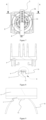
- a vehicle invisible and visible light projection device includes a light source 1, a rotary actuator 2, a light distribution element 3 and a controller.
- the light source 1 is provided with a plurality of light-emitting units 11 which is capable of independently emitting light and is arranged in sequence.
- the light-emitting units 11 select light-emitting elements that can quickly emit light and be quickly turned off, and preferably select light-emitting elements with sufficient luminous intensity and small volumes. LEDs, laser diodes, or the like may be used in the present invention.
- the light distribution element 3 is arranged in proximity to the light source 1, and used to converge light emitted by the light-emitting units 11, which on the one hand, can improve the illuminating brightness of light emitted by the light-emitting units 11, and on the one hand, can avoid mutual influence between light emitted by different light-emitting units 11, to improve the accuracy of a formed light shape.
- the light distribution element 3 is a condenser 32 arranged in front of the light source 1.
- the light source 1 is mounted on a rotating shaft of the rotary actuator 2 and can be driven by the rotary actuator 2 to rotate at a high speed.
- the plurality of light-emitting units 11 are arranged from a rotation center of the light source 1 to the periphery.
- the balance in the rotating state of the rotary actuator 2 also needs to be considered when the light distribution element 3 is arranged.
- the rotary actuator 2 selects a rotary drive device capable of rotating at a high speed and feeding back the rotating state, such as a DC motor with a rotational speed feedback electrode, and may also select a rotary drive device with precise rotational speed control, such as a servo motor.
- a controller (not shown in the figures) can receive a rotational speed signal of the rotary actuator 2, and control the light-emitting units 11 to be turned on or off at each moment, respectively, according to the rotational speed of the rotary actuator 2, so that the light-emitting units have a same on/off state within certain time when rotating to a same position, and a fixed light shape is formed due to the persistence of vision principle.
- the formed light shape may be changed by changing the on/off state of the light-emitting units 11 at a specific moment; and an animated light shape may also be formed by controlling the on/off state of the light emitting units 11 in a unit time period to change slowly according to a certain rule.
- the vehicle invisible and visible light projection device of the present invention may be used to replace a matrix headlight.
- the vehicle invisible and visible light projection device of the present invention may be used to replace a pixilated signal lamp.
- a 51-series single chip microcomputer that is widely used currently is used as the controller, and an MCS-51 single chip microcomputer is used in this embodiment, its control and programming methods are known to those skilled in the related art, and are not improved in the present invention, and thus are not described herein.
- the vehicle invisible and visible light projection device of the present invention also includes a mounting plate 4, wherein the center of the mounting plate 4 is fixed on the rotating shaft of the rotary actuator 2; the light source 1 and the light distribution element 3 are mounted on the mounting plate 4; the light-emitting units 11 on the light source 1 are arranged from the center to an edge of one side of the mounting plate 4; and the light distribution element 3 is arranged on two sides of the arrangement direction of the light-emitting units 11.
- the rotary actuator 2 drives the mounting plate 4 to rotate, thereby driving the light source 1 and the light distribution element 3 to rotate together around the rotating shaft of the rotary actuator 2.
- the mounting plate 4 may be made of an insulating material with certain mechanical strength, preferably insulating plastic with high thermal conductivity, so that on the one hand, the mounting plate 4 may be better fixed on the rotating shaft of the rotary actuator 2, and on the other hand, can better support the light source 1 to prevent vibration or deformation of the light source 1 during high-speed rotation and ensure the stability of the formed light shape.
- the light-emitting units 11 of the light source 1 are located on different rotation radii of the rotary actuator 2. At the moment, the rotational trajectory of each light-emitting unit 11 forms a circle with a different radius when the rotary actuator 2 rotates for one circle and each light-emitting unit 11 constitutes a different pixel in a rotation plane at each moment during rotation. Thus, the resolution of the formed light shape is higher.
- the light-emitting units 11 may be arranged on a line segment with one end passing through the rotating shaft of the rotary actuator 2, or may also be arranged on a plurality of line segments with one ends passing through the rotating shaft of the rotary actuator 2, or may even be scattered on a circle with the rotating shaft of the rotary actuator 2 as the center. Because the light-emitting units 11 occupy a certain area and there is a certain gap between the adjacent light-emitting units 11, the number of light-emitting units 11 that can be arranged in a radius direction is limited, and thus the accuracy of the illumination light shape or the display resolution of the vehicle invisible and visible light projection device are limited.
- the light-emitting units 11 By distributing the light-emitting units 11 at different positions in a scattered manner, there can be more light emitting-units 11 arranged on different rotation radii, and the light-emitting units 11 on different radii are controlled specially to achieve an effect equivalent to increasing the arrangement density of the light-emitting units 11 on the same radius, which can effectively improve the irradiation accuracy or display resolution of the vehicle invisible and visible light projection device to break through the package volume and arrangement distance limitations of the light-emitting units 11, thus obtaining a higher resolution of the light shape.
- the light-emitting units 11 of the light source 1 are divided into two or more than two groups, the groups are installed in different areas of the rotation plane of the rotary actuator 2, and the light-emitting units 11 in each group have different rotation radii.
- the light-emitting units 11 among different groups may have same rotation radius, or may also have different rotation radii, but in the case of same rotation radius, usually the numbers of the light-emitting units 11 in the various groups are equal, and the corresponding light-emitting units 11 have the same rotation radius.
- the light-emitting units 11 in each group may be arranged linearly along a radius of the rotation circle of the rotary actuator 2, and may also be arranged in other arrangement manners in different areas of the rotation plane of the rotary actuator 2,for example, the light-emitting units 11 may also be arranged in various manners of being arranged from the center of the circle to the circumference, such as an inclined arrangement manner, and an involute arrangement manner, and the relative positions of the light-emitting units 11 on the circumference may also be various to enrich the lighting and/or signaling functions of the vehicle invisible and visible light projection device of the present invention.
- the plurality of light-emitting units 11 are divided into at least two groups and the corresponding light-emitting units 11 in each group are arranged symmetrically on a rotation circumference of the rotary actuator 2.
- the light-emitting units 11 of the light source 1 are arranged linearly along a line segment with the rotating shaft of the rotary actuator 2 as the midpoint, that is, the light-emitting units 11 are arranged on two symmetrical radii of the rotation circle generated by rotation of the light source 1 around the rotating shaft of the rotary actuator 2.
- the light-emitting units 11 of the light source 1 are arranged along three equal-length line segments which start from the rotating shaft of the rotary actuator 2, and are spaced by 120° in sequence, that is, the light-emitting units 11 are arranged on three centrosymmetric radii of the rotation circle generated by rotation of the light source 1 around the rotating shaft of the rotary actuator 2.
- a round mounting plate 4 is provided, and the center of a circle of the mounting plate 4 is fixed on the rotating shaft of the rotary actuator 2, and the light source 1 are arranged on 6 symmetrical radii of the rotation circle of the rotary actuator 2 from the center of the mounting plate 4 to the circumferential direction.
- the arrangement of the light emitting units 11 on the symmetrical radii can ensure the balance of the light source 1 in the rotating state, and achieves convenient programming of the controller.
- the rotary actuator 2 only needs to rotate one-half (the light-emitting units 11 are located on two radii) or one-third (the light-emitting units 11 are located on three radii) circle to enable the light-emitting units 11 to cover the entire rotation circle, and the rotary actuator 2 rotates for one circle, so that the light-emitting units 11 can perform scanning three times on the same circumference, and the brightness of the vehicle invisible and visible light projection device is greatly improved, while the accuracy or resolution remains unchanged.
- the light distribution element 3 is reflectors 31 arranged in areas on two sides of the light-emitting units 11.
- the reflectors 31 are arranged on the two sides of the light-emitting units 11 to limit light emitted by the light-emitting units 11 to be within a certain range.
- a reflector 31 may be arranged on each of two sides of each group.
- the arrangement of a set of reflectors 31 on the side of the plurality of light-emitting units 11 can reduce the number of the reflectors 31 and improve the stability of the invisible and visible light projection device.
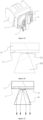
- the light distribution element 3 is a condenser 32 arranged in a light emergent surface area of the light-emitting units 11, among them, the vehicle invisible and visible light projection device of the present invention limits the condenser 32 to the feature of the condenser having a trapezoid shape as shown in Figures 13 to 15 , the embodiments shown in Figures 16 to 24 comprise alternatives to this feature, which do not fall within the subject-matter for which protection is sought.
- the condenser 32 is mostly a transparent entity made of a transparent material, and may be made of materials such as plastic or silica gel, preferably PMMA or PC.
- the condenser 32 is arranged in such a position that the axial meridian of the condenser 32 is in the same direction as the arrangement direction of the light-emitting units 11 and the light-emitting units 11 are located near a focal line of the cylindrical plano-convex lens.
- light emitted by the light-emitting units 11 is converged in the direction of the refractive power meridian of the cylindrical plano-convex lens, while no change occurs in the convergence and divergence in the direction of the axial meridian. This increases the convergence degree of light emitted by the light-emitting units11 and increases the clarity and the luminous efficacy of the light shape formed by the invisible and visible light projection device.
- Light emitted by the light-emitting units 11 is modulated and transferred by the corresponding light concentrators to form light with higher convergence degree, which is emitted from the light emergent surfaces of the light concentrators. This increases the clarity of the formed light shape and the illuminating brightness of the invisible and visible light projection device.
- the invisible and visible light projection device of the present invention may be used as an illumination tool for a vehicle traveling on the road and used as an alerting tool for emitting various vehicle driving signals. Specifically, it may be used as a strong illuminating lamp for passing beams or driving beams, but may also be used as a signal lamp such as a tail lamp, and any of various animation-type or projection-type interactive lamps.
- a vehicle invisible and visible light projection device in the present invention includes a light source 1, a rotary actuator 2 and a controller.
- the light source 1 is provided with invisible light-emitting elements 12.
- the invisible light-emitting elements 12 may be infrared LEDs, infrared laser diodes, or radar emitters.
- the rotary actuator 2 may be mounted on a bracket 6 and fixed on the housing of the vehicle lamp by means of the bracket 6.
- the rotary actuator 2 is a rotary device, which may select a rotary drive device capable of rotating at a high speed and feeding back a rotating state, such as a DC motor with a rotational speed feedback electrode, and may also select a rotary drive device with precise rotational speed control, such as a servo motor.
- the light source 1 is mounted on a rotating shaft of the rotary actuator 2, and when the rotary actuator 2 rotates, the light source 1 can be driven to rotate with the rotating shaft of the rotary actuator 2.
- the controller is electrically connected to the rotary actuator 2 and can control the rotational speed of the rotary actuator 2, and may also receive rotational speed information and rotational position information fed back by the rotary actuator 2.
- the controller is also electrically connected to the invisible light-emitting elements 12 and can control the invisible light-emitting elements 12 to emit light and stop emitting light at different time respectively according to the rotational speed information and rotational position information of the rotary actuator 2, to achieve light-emitting states of the invisible light-emitting elements 12 at different rotation positions. Irradiation of invisible light emitted by the invisible light-emitting elements 12 at different rotation positions is superimposed within certain time to create light distribution of invisible light with a certain distribution pattern. If the invisible light-emitting elements 12 are in the same light-emitting state at the same position of rotation within a certain time, invisible light emitted by the elements irradiate to create light distribution of invisible light with a specific distribution pattern fixed in a period of time.
- the distribution pattern of the formed invisible light distribution may be changed by changing the light-emitting state of the invisible light-emitting elements12 at a specific rotational position.
- the rotary actuator 2 may rotate counterclockwise or may also rotate clockwise, and the light source 1 rotates in the same direction with the rotary actuator 2.
- the light source 1 may be powered by adopting an existing device that may supply power in a rotating state, for example, a conductive slip ring is adopted to supply power to the light source 1.
- the controller may use a 51-series single chip microcomputer that is widely used currently, an MCS-51 single chip microcomputer is used in this embodiment, its control and programming methods are well known to those skilled in the related art, and are not improved in the present invention, and thus are not described in detail herein.
- a mounting plate 4 is installed on the rotating shaft of the rotary actuator 2, and the light source 1 is arranged on the mounting plate 4.
- the mounting plate 4 can provide higher mounting strength for the light source 1 and can prevent the light source 1 from vibrating during high-speed rotation, which affects the stability of invisible light irradiation.
- the light source 1 is provided with a plurality of invisible light-emitting elements 12, and the plurality of invisible light-emitting elements 12 are located on different rotation radii of the rotary actuator 2.
- the present invention does not limit the specific arrangement manner of the plurality of invisible light-emitting elements 12 which may be arranged in various possible manners.
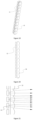
- the plurality of invisible light-emitting elements 12 may be arranged in a straight line on a side of the rotating shaft of the rotary actuator 2, as shown in Figure 28 , may be arranged on a straight line that passes through the rotating shaft of the rotary actuator 2, as shown in Figure 29 , may also be arranged on a plurality of radii uniformly distributed on a rotation plane of the rotary actuator 2, as shown in Figure 30 , or may be arranged on a plurality of diameters uniformly distributed on the rotation plane of the rotary actuator 2, as shown in Figure 31 .
- the mounting plate 4 may also be designed into different shapes, such as a rectilinear, furcated or circular shape, depending on different arrangement manners of the invisible light-emitting elements 12.
- the light source 1 further includes light-emitting units 11.
- the controller is also electrically connected to the light-emitting units 11 and can control light-emitting states of the light-emitting units 11 respectively.
- the controller can control the light-emitting units 11 to emit light and go out at different time respectively according to the rotational speed information and rotational position information fed back by the rotary actuator 2, to achieve light-emitting states of the light-emitting units 11 at different rotation positions.
- the illumination area refers to an area that can be illuminated by the irradiation of the light-emitting units 11 in a certain period of time.
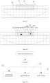
- an irradiation range formed by light emitted by the light-emitting units 11 is a visible light irradiation area M
- the visible light irradiation area M includes illumination areas M1-M12 formed by light emitted by the light emitting units 11 at different rotation positions (that is, in different periods of time), and the brightness and darkness of the illumination areas M1-M12 can be independently controlled.
- a visible light distribution formed when the illumination areas M1-M12 are all bright is the visible light irradiation area M, and different brightness-darkness combinations of the illumination areas M1-M12 form different visible light distributions.
- an irradiation range that can be formed by invisible light emitted by the invisible light-emitting elements 12 on the vehicle invisible and visible light projection device in the present invention can at least cover the irradiation range that can be formed by visible light emitted by the light-emitting units 11. In this way, whichever area within the irradiation range of visible light forms an illumination dark area due to a need in a road driving environment, the vehicle invisible and visible light projection device in the present invention can emit invisible light to form invisible light irradiation in the illumination dark area, in order to be able to monitor conditions that may affect driving safety in the illumination dark area and improve the vehicle driving safety.
- the existence of the illumination dark areas also influence an observation range of a driver of the vehicle, and form a safety hazard, and thus invisible light irradiation needs to be formed in the illumination area by the invisible light-emitting elements 12, in order to be able to monitor the safety state of the illumination dark areas by using a detection device and improve the driving safety.
- visible light emitted by the light-emitting units 11 in the vehicle invisible and visible light projection device of the present invention forms a visible light irradiation area M
- invisible light emitted by the invisible light-emitting elements 12 therein can form a separate invisible light irradiation area N1 in front of the visible light irradiation area M, and can form separate invisible light irradiation areas N2 and N3 respectively on a left side and a right side of the visible light irradiation area M.
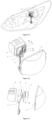
- a lens 5 is arranged on a light emergent path of the vehicle invisible and visible light projection device.
- Invisible light emitted by the invisible light-emitting elements 12 is converged by the lens 5 to be projected to form an invisible light distribution pattern.
- Light emitted by the light-emitting units 11 may also be converged by the lens 5 to be projected to form a clearer light shape of the visible light distribution.
- the invisible light distribution pattern and the light shape of the visible light distribution can also be projected farther.
- the invisible light-emitting elements 12 and/or the light-emitting units 11 are provided with a light distribution element 3.
- the embodiments as shown in Figures 33 and 34 include alternative features of condenser 32, which do not fall within the subject-matter for which protection is sought, the light distribution element 3 may be reflectors arranged on two sides of the invisible light-emitting elements 12 and/or the light-emitting units 11.
- the embodiments as shown in Figure 35 include alternative features of condenser 32, which do not fall within the subject-matter for which protection is sought, the reflectors can reflect large-angle scattered light emitted by the invisible light-emitting elements 12 and/or the light-emitting units 11, so that emitted light is more emitted in front of the light source 1 to increase the convergence degree of the emitted light, and increase the luminance of the formed light distribution.
- the light distribution element 3 may also be other optical elements which are capable of changing the light propagation direction and changing the light distribution, and arranged at a suitable position of the light source 1.
- the vehicle invisible and visible light projection device and the corresponding target object detection device of the present invention may be used in cooperation on an intelligent drive automobile.
- the vehicle invisible and visible light projection device may be not provided with an independent controller, and the light source 1 and the rotary actuator 2 of the invisible and visible light projection device are cooperated and controlled by an intelligent control device on the intelligent drive automobile, and information detected by the target object detection device may be analyzed and processed by the intelligent control device.
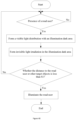
- the vehicle invisible and visible light projection device may also be provided with an independent controller, as shown in Figure 39 , and information detected by the target object detection device is transmitted to the controller which analyzes the influence of a target object on the vehicle driving safety and controls the invisible light-emitting elements 12, the light-emitting units 11 and the rotary actuator 2 to work in a cooperation manner to form the corresponding invisible light distribution and visible light distribution, to ensure the vehicle driving safety and the safety of the target object.
- the controller may also be connected to the intelligent control device on the intelligent drive automobile, and when necessary, the driving status of the intelligent drive automobile may also be adjusted and controlled by the intelligent control device on the intelligent drive automobile, to achieve intelligent control of the automobile and improve the safety performance of the intelligent drive automobile.
Landscapes
- Engineering & Computer Science (AREA)
- General Engineering & Computer Science (AREA)
- Physics & Mathematics (AREA)
- Optics & Photonics (AREA)
- Microelectronics & Electronic Packaging (AREA)
- Mechanical Engineering (AREA)
- Radar, Positioning & Navigation (AREA)
- Remote Sensing (AREA)
- Non-Portable Lighting Devices Or Systems Thereof (AREA)
- Lighting Device Outwards From Vehicle And Optical Signal (AREA)
Claims (10)
- Dispositif de projection de lumière invisible et visible pour véhicule, comprenant une source de lumière (1), un actionneur rotatif (2), un élément de distribution de lumière (3) et un dispositif de commande, la source de lumière (1) étant montée sur un arbre rotatif de l'actionneur rotatif (2), le dispositif de commande étant adapté pour commander un état d'émission de lumière de la source de lumière (1) pour créer des différentes formes de lumière,l'élément de distribution de lumière (3) étant disposé dans une zone à proximité de la source de lumière (1), la source de lumière (1) comprenant plusieurs unités d'émission de lumière (11) et éléments d'émission de lumière invisible (12) pouvant être commandés indépendamment, l'élément de distribution de lumière (3) étant adapté pour focaliser la lumière émise par les unités d'émission de lumière (11) et les éléments d'émission de lumière invisible (12), le dispositif de commande étant relié électriquement aux unités d'émission de lumière (11), aux éléments d'émission de lumière invisible (12) et à un actionneur rotatif (2), le dispositif de commande pouvant commander les états d'émission de lumière des unités d'émission de lumière (11) à différentes positions rotatives pour créer une distribution de lumière visible, le dispositif de commande pouvant commander les états d'émission de lumière des éléments d'émission de lumière invisible (12) à différentes positions rotatives pour créer une distribution de lumière invisible,l'élément de distribution de lumière (3) étant un condenseur (32) disposé dans une zone de surface d'émergence de lumière des unités d'émission de lumière (11) et des éléments d'émission de lumière invisible (12), le condenseur (32) comprenant une surface d'incidence de lumière et une surface d'émergence de lumière, la surface d'incidence de lumière du condenseur (32) étant adapté pour introduire la lumière émise par les unités d'émission de lumière (11) et les éléments d'émission de lumière invisible (12), la lumière focalisée par le condenseur (32) étant adaptée pour être émise depuis la surface d'émergence de lumière du condenseur (32), le condenseur (32) étant un dispositif transparent en forme de bande avec une section transversale en forme de trapèze isocèle, une surface sur laquelle est située une base supérieure du trapèze isocèle étant la surface d'incidence de lumière du condenseur (32), et une surface sur laquelle est située une base inférieure du trapèze isocèle étant la surface d'émergence de lumière du condenseur (32).
- Dispositif de projection de lumière invisible et visible pour véhicule selon la revendication 1, dans lequel le dispositif de commande est adapté pour commander les unités d'émission de lumière (11) de telle sorte qu'elles sont allumées ou éteindues en fonction d'une vitesse rotative de l'actionneur rotatif (2).
- Dispositif de projection de lumière visible et invisible pour véhicule selon la revendication 2, dans lequel les unités d'émission de lumière (11) sont situées sur des rayons rotatifs différents de l'actionneur rotatif (2), ou les unités d'émission de lumière (11) sont divisées en au moins deux groupes, et les unités d'émission de lumière (11) dans chaque groupe d'unités d'émission de lumière (11) sont situées sur des rayons rotatifs différents de l'actionneur rotatif (2), ou les unités d'émission de lumière (11) sont divisées en au moins deux groupes, et chaque groupe d'unités d'émission de lumière (11) est disposé symétriquement sur une circonférence rotative de l'actionneur rotatif (2).
- Dispositif de projection de lumière invisible et visible pour véhicule selon l'une quelconque des revendications 1 à 3, dans lequel le condenseur (32) est disposé dans la zone de surface d'émergence de lumière des plusieurs unités d'émission de lumière (11).
- Dispositif de projection de lumière visible et invisible pour véhicule selon l'une quelconque des revendications 1 à 4, dans lequel il y a plusieurs éléments d'émission de lumière invisible (12) situées sur des rayons rotatifs différents de l'actionneur rotatif (2).
- Dispositif de projection de lumière invisible et visible pour véhicule selon la revendication 2 ou 5, comprenant en outre une plaque de montage (4), la plaque de montage (4) étant montée sur un arbre rotatif de l'actionneur rotatif (2), et la source de lumière (1) étant montée sur la plaque de montage (4).
- Dispositif de projection de lumière visible et invisible pour véhicule selon la revendication 1 ou 5, dans lequel une plage d'irradiation de la lumière invisible émise par les éléments d'émission de lumière invisible (12) peut couvrir au moins une plage d'irradiation de la lumière visible émise par les unités d'émission de lumière (11),
la lumière invisible émise par les éléments d'émission de lumière invisible (12) pouvant de plus de préférence former des zones d'irradiation de lumière invisible séparées (N1, N2, N3) en dehors de la plage d'irradiation de la lumière visible. - Dispositif de projection de lumière invisible et visible pour véhicule selon la revendication 7, comprenant en outre une lentille (5), la lentille (5) pouvant projeter de la lumière invisible émise par les éléments d'émission de lumière invisible (12) et de la lumière visible émise par les unités d'émission de lumière (11).
- Dispositif de projection de lumière invisible et visible pour véhicule selon l'une quelconque des revendications 1 à 8 en combinaison avec un dispositif de détection d'objet cible comprenant un dispositif de détection de lumière invisible pouvant détecter des objets cibles dans la plage d'irradiation de la lumière invisible formée par ledit dispositif de projection de lumière invisible et visible.
- Dispositif de projection de lumière visible et invisible pour véhicule en combinaison avec un dispositif de détection d'objet cible selon la revendication 9, comprenant en outre un dispositif de détection de lumière visible, le dispositif de détection de lumière visible pouvant détecter des objets cibles dans la plage d'irradiation de la lumière visible formée par les unités d'émission de lumière (11).
Applications Claiming Priority (3)
| Application Number | Priority Date | Filing Date | Title |
|---|---|---|---|
| CN201922119431.0U CN211316066U (zh) | 2019-11-27 | 2019-11-27 | 车辆照明装置及车辆 |
| CN202020045138.4U CN211442116U (zh) | 2020-01-09 | 2020-01-09 | 车辆不可见光投射装置、目标物检测装置及智能驾驶汽车 |
| PCT/CN2020/131345 WO2021104286A1 (fr) | 2019-11-27 | 2020-11-25 | Dispositif d'éclairage de véhicule, dispositif de projection de lumière invisible de véhicule, et dispositif de détection d'objet cible |
Publications (4)
| Publication Number | Publication Date |
|---|---|
| EP4006409A1 EP4006409A1 (fr) | 2022-06-01 |
| EP4006409A4 EP4006409A4 (fr) | 2022-08-31 |
| EP4006409B1 true EP4006409B1 (fr) | 2025-03-19 |
| EP4006409C0 EP4006409C0 (fr) | 2025-03-19 |
Family
ID=76129921
Family Applications (1)
| Application Number | Title | Priority Date | Filing Date |
|---|---|---|---|
| EP20894534.5A Active EP4006409B1 (fr) | 2019-11-27 | 2020-11-25 | Dispositif d'éclairage de véhicule, dispositif de projection de lumière invisible de véhicule, et dispositif de détection d'objet cible |
Country Status (6)
| Country | Link |
|---|---|
| US (1) | US11780362B2 (fr) |
| EP (1) | EP4006409B1 (fr) |
| JP (1) | JP7317219B2 (fr) |
| KR (1) | KR102728244B1 (fr) |
| MX (1) | MX2021011504A (fr) |
| WO (1) | WO2021104286A1 (fr) |
Families Citing this family (3)
| Publication number | Priority date | Publication date | Assignee | Title |
|---|---|---|---|---|
| TWI866702B (zh) * | 2023-02-06 | 2024-12-11 | 王正 | 智能隨動照明裝置 |
| TWI851003B (zh) * | 2023-02-06 | 2024-08-01 | 王正 | 智能隨動照明裝置 |
| CN119617328A (zh) * | 2025-01-13 | 2025-03-14 | 浙江零跑科技股份有限公司 | 用于车辆的车灯投射系统以及车辆 |
Citations (5)
| Publication number | Priority date | Publication date | Assignee | Title |
|---|---|---|---|---|
| US20020005826A1 (en) * | 2000-05-16 | 2002-01-17 | Pederson John C. | LED sign |
| US20060239018A1 (en) * | 2005-04-22 | 2006-10-26 | Dei Headquarters, Inc. | Display system using wheel-mounted strips of flashing lights |
| EP2827048A1 (fr) * | 2012-03-15 | 2015-01-21 | Koito Manufacturing Co., Ltd. | Dispositif électroluminescent et appareil d'éclairage pour véhicule |
| WO2016093154A1 (fr) * | 2014-12-08 | 2016-06-16 | 株式会社小糸製作所 | Dispositif d'éclairage de véhicule |
| US20190035317A1 (en) * | 2017-07-28 | 2019-01-31 | Magic Leap, Inc. | Fan assembly for displaying an image |
Family Cites Families (17)
| Publication number | Priority date | Publication date | Assignee | Title |
|---|---|---|---|---|
| DE20115799U1 (de) * | 2001-09-26 | 2002-03-07 | Merlaku, Kastriot, 80807 München | Scheinwerfer für Fahrzeug |
| US6828544B2 (en) * | 2002-06-12 | 2004-12-07 | Ford Global Technologies, Llc | Active night vision system for vehicles employing anti-blinding scheme |
| DE102006019287A1 (de) * | 2006-04-26 | 2007-10-31 | Bayerische Motoren Werke Ag | Kraftfahrzeugscheinwerfer |
| WO2010093278A1 (fr) * | 2009-02-16 | 2010-08-19 | ДЯДЕЧКО, Иван Петрович | Phare à caractéristiques d'éclairage changeantes |
| JP5316238B2 (ja) * | 2009-06-08 | 2013-10-16 | 市光工業株式会社 | 車両用灯具 |
| US20130215635A1 (en) * | 2012-02-22 | 2013-08-22 | Osram Sylvania Inc. | Automotive headlamp having a beam changing assembly |
| WO2013132386A1 (fr) | 2012-03-08 | 2013-09-12 | Koninklijke Philips N.V. | Eclairage à luminance élevée commandable doté de sources lumineuses mobiles |
| JP6190702B2 (ja) | 2013-11-25 | 2017-08-30 | スタンレー電気株式会社 | 照射装置 |
| KR20150073682A (ko) | 2013-12-23 | 2015-07-01 | 에스엘 주식회사 | 차량용 램프 및 상기 차량용 램프를 제어하는 방법 |
| JP5970572B1 (ja) * | 2015-02-13 | 2016-08-17 | 株式会社フジクラ | 車両用ヘッドランプ |
| JP6621697B2 (ja) * | 2016-03-30 | 2019-12-18 | 株式会社小糸製作所 | 車両用灯具 |
| JP6691806B2 (ja) * | 2016-04-06 | 2020-05-13 | 株式会社小糸製作所 | 車両用灯具 |
| JP2018063891A (ja) * | 2016-10-13 | 2018-04-19 | 株式会社小糸製作所 | 光源ユニットおよび灯具 |
| US10924685B2 (en) * | 2018-05-07 | 2021-02-16 | Rubicon Products, LLC | Night vision apparatus |
| WO2020039890A1 (fr) * | 2018-08-22 | 2020-02-27 | 株式会社小糸製作所 | Unité de source de lumière et lampe |
| CN211316066U (zh) * | 2019-11-27 | 2020-08-21 | 华域视觉科技(上海)有限公司 | 车辆照明装置及车辆 |
| CN211442116U (zh) * | 2020-01-09 | 2020-09-08 | 华域视觉科技(上海)有限公司 | 车辆不可见光投射装置、目标物检测装置及智能驾驶汽车 |
-
2020
- 2020-11-25 MX MX2021011504A patent/MX2021011504A/es unknown
- 2020-11-25 KR KR1020227007819A patent/KR102728244B1/ko active Active
- 2020-11-25 WO PCT/CN2020/131345 patent/WO2021104286A1/fr not_active Ceased
- 2020-11-25 EP EP20894534.5A patent/EP4006409B1/fr active Active
- 2020-11-25 JP JP2022513954A patent/JP7317219B2/ja active Active
- 2020-11-25 US US17/640,222 patent/US11780362B2/en active Active
Patent Citations (5)
| Publication number | Priority date | Publication date | Assignee | Title |
|---|---|---|---|---|
| US20020005826A1 (en) * | 2000-05-16 | 2002-01-17 | Pederson John C. | LED sign |
| US20060239018A1 (en) * | 2005-04-22 | 2006-10-26 | Dei Headquarters, Inc. | Display system using wheel-mounted strips of flashing lights |
| EP2827048A1 (fr) * | 2012-03-15 | 2015-01-21 | Koito Manufacturing Co., Ltd. | Dispositif électroluminescent et appareil d'éclairage pour véhicule |
| WO2016093154A1 (fr) * | 2014-12-08 | 2016-06-16 | 株式会社小糸製作所 | Dispositif d'éclairage de véhicule |
| US20190035317A1 (en) * | 2017-07-28 | 2019-01-31 | Magic Leap, Inc. | Fan assembly for displaying an image |
Also Published As
| Publication number | Publication date |
|---|---|
| EP4006409A4 (fr) | 2022-08-31 |
| KR102728244B1 (ko) | 2024-11-07 |
| US11780362B2 (en) | 2023-10-10 |
| EP4006409A1 (fr) | 2022-06-01 |
| JP7317219B2 (ja) | 2023-07-28 |
| WO2021104286A1 (fr) | 2021-06-03 |
| EP4006409C0 (fr) | 2025-03-19 |
| JP2022547011A (ja) | 2022-11-10 |
| KR20220044337A (ko) | 2022-04-07 |
| MX2021011504A (es) | 2021-10-22 |
| US20220314867A1 (en) | 2022-10-06 |
Similar Documents
| Publication | Publication Date | Title |
|---|---|---|
| CN104296037B (zh) | 车辆用灯具 | |
| US5592578A (en) | Peripheral optical element for redirecting light from an LED | |
| JP5815995B2 (ja) | 車両用灯具用の光学ユニット | |
| US10670216B2 (en) | Vehicle lamp including rotary reflector | |
| US11780362B2 (en) | Vehicle having a visible and non-visible lighting projection device with a light source mounted on a rotary actuator | |
| US8920009B2 (en) | Lamp device for vehicle | |
| JP2021518979A (ja) | 車両ランプ用光学素子、車両ランプモジュール、車両ヘッドライト及び車両 | |
| KR20080005527A (ko) | 자동차 헤드라이트 | |
| JP2015185533A (ja) | 車載用前照灯 | |
| CN211316066U (zh) | 车辆照明装置及车辆 | |
| JP2016110853A (ja) | 車両用前照灯 | |
| WO2020051269A1 (fr) | Projecteur adaptatif pour la mise en forme optique et électronique d'une lumière | |
| CN104890564A (zh) | 车辆前照灯 | |
| CN110145720B (zh) | 远近光一体的车灯模组 | |
| US10267474B2 (en) | Vehicle lighting and/or signaling device having a steerable dynamic beam | |
| CN114060761B (zh) | 具备路面描绘功能的车辆用灯具 | |
| JP2007149552A (ja) | 照明装置 | |
| CN211442116U (zh) | 车辆不可见光投射装置、目标物检测装置及智能驾驶汽车 | |
| JPWO2020161846A1 (ja) | 投影装置 | |
| WO2022134456A1 (fr) | Module de phare de véhicule à faisceau de conduite adaptatif (adb), phare de véhicule et véhicule | |
| CN207471429U (zh) | 一种光学调节随动大灯及汽车 | |
| JP2009266659A (ja) | 警告灯 | |
| CN209762933U (zh) | 远近光一体的车灯模组 | |
| WO2018082224A1 (fr) | Module optique de phare d'automobile à haute résolution et procédé de commande d'éclairage à faisceau élevé à haute résolution associé | |
| CN113701121B (zh) | 昼间行车灯光学系统、led昼间行车组合灯以及车辆led组合灯 |
Legal Events
| Date | Code | Title | Description |
|---|---|---|---|
| STAA | Information on the status of an ep patent application or granted ep patent |
Free format text: STATUS: THE INTERNATIONAL PUBLICATION HAS BEEN MADE |
|
| PUAI | Public reference made under article 153(3) epc to a published international application that has entered the european phase |
Free format text: ORIGINAL CODE: 0009012 |
|
| STAA | Information on the status of an ep patent application or granted ep patent |
Free format text: STATUS: REQUEST FOR EXAMINATION WAS MADE |
|
| 17P | Request for examination filed |
Effective date: 20220225 |
|
| AK | Designated contracting states |
Kind code of ref document: A1 Designated state(s): AL AT BE BG CH CY CZ DE DK EE ES FI FR GB GR HR HU IE IS IT LI LT LU LV MC MK MT NL NO PL PT RO RS SE SI SK SM TR |
|
| A4 | Supplementary search report drawn up and despatched |
Effective date: 20220803 |
|
| RIC1 | Information provided on ipc code assigned before grant |
Ipc: B60Q 1/06 20060101ALI20220728BHEP Ipc: F21S 41/663 20180101AFI20220728BHEP |
|
| DAV | Request for validation of the european patent (deleted) | ||
| DAX | Request for extension of the european patent (deleted) | ||
| STAA | Information on the status of an ep patent application or granted ep patent |
Free format text: STATUS: EXAMINATION IS IN PROGRESS |
|
| 17Q | First examination report despatched |
Effective date: 20230517 |
|
| GRAP | Despatch of communication of intention to grant a patent |
Free format text: ORIGINAL CODE: EPIDOSNIGR1 |
|
| STAA | Information on the status of an ep patent application or granted ep patent |
Free format text: STATUS: GRANT OF PATENT IS INTENDED |
|
| INTG | Intention to grant announced |
Effective date: 20241021 |
|
| GRAS | Grant fee paid |
Free format text: ORIGINAL CODE: EPIDOSNIGR3 |
|
| GRAA | (expected) grant |
Free format text: ORIGINAL CODE: 0009210 |
|
| STAA | Information on the status of an ep patent application or granted ep patent |
Free format text: STATUS: THE PATENT HAS BEEN GRANTED |
|
| AK | Designated contracting states |
Kind code of ref document: B1 Designated state(s): AL AT BE BG CH CY CZ DE DK EE ES FI FR GB GR HR HU IE IS IT LI LT LU LV MC MK MT NL NO PL PT RO RS SE SI SK SM TR |
|
| REG | Reference to a national code |
Ref country code: GB Ref legal event code: FG4D |
|
| REG | Reference to a national code |
Ref country code: CH Ref legal event code: EP |
|
| REG | Reference to a national code |
Ref country code: IE Ref legal event code: FG4D |
|
| REG | Reference to a national code |
Ref country code: DE Ref legal event code: R096 Ref document number: 602020048125 Country of ref document: DE |
|
| U01 | Request for unitary effect filed |
Effective date: 20250319 |
|
| U07 | Unitary effect registered |
Designated state(s): AT BE BG DE DK EE FI FR IT LT LU LV MT NL PT RO SE SI Effective date: 20250325 |
|
| PG25 | Lapsed in a contracting state [announced via postgrant information from national office to epo] |
Ref country code: RS Free format text: LAPSE BECAUSE OF FAILURE TO SUBMIT A TRANSLATION OF THE DESCRIPTION OR TO PAY THE FEE WITHIN THE PRESCRIBED TIME-LIMIT Effective date: 20250619 |
|
| PG25 | Lapsed in a contracting state [announced via postgrant information from national office to epo] |
Ref country code: NO Free format text: LAPSE BECAUSE OF FAILURE TO SUBMIT A TRANSLATION OF THE DESCRIPTION OR TO PAY THE FEE WITHIN THE PRESCRIBED TIME-LIMIT Effective date: 20250619 |
|
| PG25 | Lapsed in a contracting state [announced via postgrant information from national office to epo] |
Ref country code: HR Free format text: LAPSE BECAUSE OF FAILURE TO SUBMIT A TRANSLATION OF THE DESCRIPTION OR TO PAY THE FEE WITHIN THE PRESCRIBED TIME-LIMIT Effective date: 20250319 |
|
| PG25 | Lapsed in a contracting state [announced via postgrant information from national office to epo] |
Ref country code: GR Free format text: LAPSE BECAUSE OF FAILURE TO SUBMIT A TRANSLATION OF THE DESCRIPTION OR TO PAY THE FEE WITHIN THE PRESCRIBED TIME-LIMIT Effective date: 20250620 |
|
| PG25 | Lapsed in a contracting state [announced via postgrant information from national office to epo] |
Ref country code: SM Free format text: LAPSE BECAUSE OF FAILURE TO SUBMIT A TRANSLATION OF THE DESCRIPTION OR TO PAY THE FEE WITHIN THE PRESCRIBED TIME-LIMIT Effective date: 20250319 |
|
| PG25 | Lapsed in a contracting state [announced via postgrant information from national office to epo] |
Ref country code: ES Free format text: LAPSE BECAUSE OF FAILURE TO SUBMIT A TRANSLATION OF THE DESCRIPTION OR TO PAY THE FEE WITHIN THE PRESCRIBED TIME-LIMIT Effective date: 20250319 |
|
| PG25 | Lapsed in a contracting state [announced via postgrant information from national office to epo] |
Ref country code: PL Free format text: LAPSE BECAUSE OF FAILURE TO SUBMIT A TRANSLATION OF THE DESCRIPTION OR TO PAY THE FEE WITHIN THE PRESCRIBED TIME-LIMIT Effective date: 20250319 |
|
| PG25 | Lapsed in a contracting state [announced via postgrant information from national office to epo] |
Ref country code: CZ Free format text: LAPSE BECAUSE OF FAILURE TO SUBMIT A TRANSLATION OF THE DESCRIPTION OR TO PAY THE FEE WITHIN THE PRESCRIBED TIME-LIMIT Effective date: 20250319 |
|
| U20 | Renewal fee for the european patent with unitary effect paid |
Year of fee payment: 6 Effective date: 20250918 |
|
| PG25 | Lapsed in a contracting state [announced via postgrant information from national office to epo] |
Ref country code: SK Free format text: LAPSE BECAUSE OF FAILURE TO SUBMIT A TRANSLATION OF THE DESCRIPTION OR TO PAY THE FEE WITHIN THE PRESCRIBED TIME-LIMIT Effective date: 20250319 |
|
| PG25 | Lapsed in a contracting state [announced via postgrant information from national office to epo] |
Ref country code: IS Free format text: LAPSE BECAUSE OF FAILURE TO SUBMIT A TRANSLATION OF THE DESCRIPTION OR TO PAY THE FEE WITHIN THE PRESCRIBED TIME-LIMIT Effective date: 20250719 |
|
| PLBE | No opposition filed within time limit |
Free format text: ORIGINAL CODE: 0009261 |
|
| STAA | Information on the status of an ep patent application or granted ep patent |
Free format text: STATUS: NO OPPOSITION FILED WITHIN TIME LIMIT |
|
| REG | Reference to a national code |
Ref country code: CH Ref legal event code: L10 Free format text: ST27 STATUS EVENT CODE: U-0-0-L10-L00 (AS PROVIDED BY THE NATIONAL OFFICE) Effective date: 20260128 |
|
| 26N | No opposition filed |
Effective date: 20251222 |