EP4006424A1 - Heizungsherd - Google Patents
Heizungsherd Download PDFInfo
- Publication number
- EP4006424A1 EP4006424A1 EP20846465.1A EP20846465A EP4006424A1 EP 4006424 A1 EP4006424 A1 EP 4006424A1 EP 20846465 A EP20846465 A EP 20846465A EP 4006424 A1 EP4006424 A1 EP 4006424A1
- Authority
- EP
- European Patent Office
- Prior art keywords
- heating cooking
- pull
- cooking apparatus
- cooking chamber
- heated
- Prior art date
- Legal status (The legal status is an assumption and is not a legal conclusion. Google has not performed a legal analysis and makes no representation as to the accuracy of the status listed.)
- Granted
Links
Images


Classifications
-
- H—ELECTRICITY
- H05—ELECTRIC TECHNIQUES NOT OTHERWISE PROVIDED FOR
- H05B—ELECTRIC HEATING; ELECTRIC LIGHT SOURCES NOT OTHERWISE PROVIDED FOR; CIRCUIT ARRANGEMENTS FOR ELECTRIC LIGHT SOURCES, IN GENERAL
- H05B6/00—Heating by electric, magnetic or electromagnetic fields
- H05B6/64—Heating using microwaves
-
- F—MECHANICAL ENGINEERING; LIGHTING; HEATING; WEAPONS; BLASTING
- F24—HEATING; RANGES; VENTILATING
- F24C—DOMESTIC STOVES OR RANGES ; DETAILS OF DOMESTIC STOVES OR RANGES, OF GENERAL APPLICATION
- F24C7/00—Stoves or ranges heated by electric energy
- F24C7/02—Stoves or ranges heated by electric energy using microwaves
-
- F—MECHANICAL ENGINEERING; LIGHTING; HEATING; WEAPONS; BLASTING
- F24—HEATING; RANGES; VENTILATING
- F24C—DOMESTIC STOVES OR RANGES ; DETAILS OF DOMESTIC STOVES OR RANGES, OF GENERAL APPLICATION
- F24C15/00—Details
- F24C15/02—Doors specially adapted for stoves or ranges
-
- F—MECHANICAL ENGINEERING; LIGHTING; HEATING; WEAPONS; BLASTING
- F24—HEATING; RANGES; VENTILATING
- F24C—DOMESTIC STOVES OR RANGES ; DETAILS OF DOMESTIC STOVES OR RANGES, OF GENERAL APPLICATION
- F24C15/00—Details
- F24C15/16—Shelves, racks or trays inside ovens; Supports therefor
-
- F—MECHANICAL ENGINEERING; LIGHTING; HEATING; WEAPONS; BLASTING
- F24—HEATING; RANGES; VENTILATING
- F24C—DOMESTIC STOVES OR RANGES ; DETAILS OF DOMESTIC STOVES OR RANGES, OF GENERAL APPLICATION
- F24C15/00—Details
- F24C15/16—Shelves, racks or trays inside ovens; Supports therefor
- F24C15/162—Co-operating with a door, e.g. operated by the door
-
- H—ELECTRICITY
- H05—ELECTRIC TECHNIQUES NOT OTHERWISE PROVIDED FOR
- H05B—ELECTRIC HEATING; ELECTRIC LIGHT SOURCES NOT OTHERWISE PROVIDED FOR; CIRCUIT ARRANGEMENTS FOR ELECTRIC LIGHT SOURCES, IN GENERAL
- H05B6/00—Heating by electric, magnetic or electromagnetic fields
- H05B6/64—Heating using microwaves
- H05B6/6402—Aspects relating to the microwave cavity
-
- H—ELECTRICITY
- H05—ELECTRIC TECHNIQUES NOT OTHERWISE PROVIDED FOR
- H05B—ELECTRIC HEATING; ELECTRIC LIGHT SOURCES NOT OTHERWISE PROVIDED FOR; CIRCUIT ARRANGEMENTS FOR ELECTRIC LIGHT SOURCES, IN GENERAL
- H05B6/00—Heating by electric, magnetic or electromagnetic fields
- H05B6/64—Heating using microwaves
- H05B6/6414—Aspects relating to the door of the microwave heating apparatus
-
- H—ELECTRICITY
- H05—ELECTRIC TECHNIQUES NOT OTHERWISE PROVIDED FOR
- H05B—ELECTRIC HEATING; ELECTRIC LIGHT SOURCES NOT OTHERWISE PROVIDED FOR; CIRCUIT ARRANGEMENTS FOR ELECTRIC LIGHT SOURCES, IN GENERAL
- H05B6/00—Heating by electric, magnetic or electromagnetic fields
- H05B6/64—Heating using microwaves
- H05B6/6426—Aspects relating to the exterior of the microwave heating apparatus, e.g. metal casing, power cord
-
- H—ELECTRICITY
- H05—ELECTRIC TECHNIQUES NOT OTHERWISE PROVIDED FOR
- H05B—ELECTRIC HEATING; ELECTRIC LIGHT SOURCES NOT OTHERWISE PROVIDED FOR; CIRCUIT ARRANGEMENTS FOR ELECTRIC LIGHT SOURCES, IN GENERAL
- H05B6/00—Heating by electric, magnetic or electromagnetic fields
- H05B6/64—Heating using microwaves
- H05B6/72—Radiators or antennas
- H05B6/725—Rotatable antennas
Definitions
- the present invention relates to a heating cooking apparatus.
- PTL 1 discloses a pull-out heating cooking apparatus.
- the pull-out heating cooking apparatus disclosed in PTL 1 includes a heating cooking apparatus main body and a pull-out body.
- the heating cooking apparatus main body includes a heating cooking chamber.
- the pull-out body can be drawn toward the outside of the heating cooking apparatus main body from a state where the pull-out body is accommodated in the heating cooking chamber.
- Heating functions of the pull-out heating cooking apparatus disclosed in PTL 1 include a microwave heating function and a rapid hot air heating function.
- the microwave heating function is a function of applying microwaves toward an object to be heated.
- a microwave radiation port is formed in a side wall of the heating cooking chamber.
- an object of the present invention is to provide a heating cooking apparatus that can efficiently irradiate an object to be heated with microwaves.
- a heating cooking apparatus of the present invention includes a heating cooking chamber and a microwave supply unit. An object to be heated is accommodated in the heating cooking chamber.
- the microwave supply unit includes a radiation port and supplies microwaves to the heating cooking chamber through the radiation port. The radiation port is positioned below the heating cooking chamber.
- an object to be heated can be efficiently irradiated with microwaves.
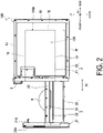
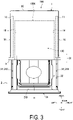
- FIG. 1 is a perspective view illustrating an appearance of the pull-out heating cooking apparatus 100 according to the present embodiment.
- FIG. 2 is a right side view illustrating the pull-out heating cooking apparatus 100 according to the present embodiment.
- FIG. 3 is a top view illustrating the pull-out heating cooking apparatus 100 according to the present embodiment. More specifically, FIG. 1 to FIG. 3 illustrate the pull-out heating cooking apparatus 100 in a state where a pull-out body 2 is pulled out. Further, FIG. 1 illustrates the appearance of the pull-out heating cooking apparatus 100 when viewed from above obliquely from the right.
- the pull-out heating cooking apparatus 100 is one example of a heating cooking apparatus.
- the pull-out heating cooking apparatus 100 heats and cooks an object H to be heated.
- the object H to be heated is, for example, a food product.
- the pull-out heating cooking apparatus 100 includes a heating chamber 1, the pull-out body 2, an operation panel 3, a control unit 5, and a storage unit 6.
- a side on which the operation panel 3 of the pull-out heating cooking apparatus 100 is disposed is defined as a front side of the pull-out heating cooking apparatus 100, and a side opposite to the front side is defined as a rear side of the pull-out heating cooking apparatus 100.
- a right side of the pull-out heating cooking apparatus 100 when the pull-out heating cooking apparatus 100 is viewed from the front side is defined as a right side, and a side opposite to the right side is defined as a left side of the pull-out heating cooking apparatus 100.
- a side on which the operation panel 3 is disposed is defined as an upper side of the pull-out heating cooking apparatus 100, and a side opposite to the upper side is defined as a lower side of the pull-out heating cooking apparatus 100. Note that these orientations do not limit the orientation of the pull-out heating cooking apparatus according to the present invention when in use.
- the heating chamber 1 is a box-like member. Specifically, the heating chamber 1 includes a right outer wall 1G, a left outer wall 1H, a top outer wall 1J, a bottom outer wall 1F, and a back outer wall 1K. The heating chamber 1 also includes a heating cooking chamber 100A therein.
- the heating cooking chamber 100A includes an accommodation space 120 that accommodates the object H to be heated.
- the accommodation space 120 is a space that can accommodate the object to be heated H and has a predetermined volume.
- the heating cooking chamber 100A includes a right wall 1A, a left wall 1B, a top wall 1C, a bottom wall 1D, and a back wall 1E.
- the shape of the heating cooking chamber 100A is, for example, a substantially rectangular parallelepiped shape. Materials of the right wall 1A, the left wall 1B, the top wall 1C, the bottom wall 1D, and the back wall 1E are, for example, a metal.
- the front side of the heating cooking chamber 100A is opened for allowing the object to be heated H to be inserted and removed.
- the heating chamber 1 further includes a space between the bottom wall 1D and the bottom outer wall 1F.
- the heating chamber 1 further includes a space between the right wall 1A and the right outer wall 1G.
- the heating chamber 1 further includes a space between the left wall 1B and the left outer wall 1H.
- the heating chamber 1 further includes a space between the top wall 1C and the top outer wall 1J.
- the heating chamber 1 further includes a space between the back wall 1E and the back outer wall 1K.
- the operation panel 3 includes an operation unit and a display portion.
- the operation unit receives an operation from a user.
- the operation unit includes various types of keys.
- the display portion displays various pieces of information.
- the display portion includes a liquid crystal panel.
- the operation panel 3 is located on an upper portion of a front face of the heating chamber 1.
- the storage unit 6 includes a random access memory (RAM) and a read only memory (ROM).
- the storage unit 6 stores control programs used for controlling operations of each part of the pull-out heating cooking apparatus 100.
- the storage unit 6 stores setting information input when the operation panel 3 is operated.
- the control unit 5 is a hardware circuit that includes a processor such as a central processing unit (CPU).
- the control unit 5 executes a control program stored in the storage unit 6.
- FIG. 4 is a perspective view of the pull-out body 2 and the placing portion 22 according to the present embodiment.
- the pull-out heating cooking apparatus 100 further includes the placing portion 22.
- the pull-out body 2 is freely pulled out from the heating cooking chamber 100A along a predetermined direction D1.
- the predetermined direction D1 is a direction along a front-rear direction. More specifically, the pull-out body 2 can be pulled out and pulled in with respect to the heating chamber 1.
- the pull-out body 2 includes a pull-out main body 20.
- the pull-out main body 20 includes a door portion 21 and a support portion 23.
- the object H to be heated can be placed on the placing portion 22.
- the placing portion 22 is, for example, a plate-like member made of a ceramic, glass, or a synthetic resin, and is preferably a plate-like member made of a ceramic or glass. As a result, the placing portion 22 transmits microwaves. In addition, the placing portion 22 is transparent or translucent. The term "translucent" includes color transparency.
- the door portion 21 can open and close an opening on the front side of the heating cooking chamber 100A.
- the door portion 21 is a substantially rectangular plate-like member.
- the door portion 21 includes a front face 21A and a rear face 21B.
- the door portion 21 opens the opening on the front side of the heating cooking chamber 100A in a state where the pull-out body 2 is pulled out of the heating cooking chamber 100A.
- the door portion 21 closes the opening on the front side of the heating cooking chamber 100A in a state where the pull-out body 2 is pulled into the heating cooking chamber 100A. Meanwhile, in a state where the pull-out body 2 is pushed into the heating cooking chamber 100A, a distance between the top wall 1C and the bottom wall 1D is shorter than a distance between the back wall 1E and the rear face 21B.
- the support portion 23 is fixed to the rear face 21B of the door portion 21, and supports a peripheral portion of the placing portion 22 such that the placing portion 22 is held in a horizontal state.
- the support portion 23 includes a base plate portion 23A, a back plate portion 23B, a right plate portion 23C, a left plate portion 23D, and a pair of rollers 23E.
- the base plate portion 23A includes a rectangular opening 23A1.
- the rectangular opening 23A1 is positioned at a substantially center portion of the base plate portion 23A.
- the back plate portion 23B, the right plate portion 23C, and the left plate portion 23D are erected upward from a peripheral portion of the base plate portion 23A.
- the placing portion 22 is fitted between the door portion 21, the back plate portion 23B, the right plate portion 23C, and the left plate portion 23D.
- the peripheral portion of the placing portion 22 is fixed to the upper face of the peripheral portion of the base plate portion 23A.
- the pair of rollers 23E are rotated as the pull-out body 2 moves.
- the pair of rollers 23E include a right roller 23E1 and a left roller 23E2.
- the right roller 23E1 is attached to a rear end of the right plate portion 23C.
- the left roller 23E2 is attached to a rear end of the left plate portion 23D.
- the placing portion 22 and the support portion 23 are pulled out of the heating cooking chamber 100A to the outside by pulling out the pull-out body 2.
- the placing portion 22 and the support portion 23 are accommodated in the heating cooking chamber 100A in a state where the pull-out body 2 is pulled in.
- the placing portion 22 is transparent or translucent, and thus a user or the like can visually recognize an object present below the placing portion 22.
- the user or the like can easily clean the bottom wall 1D when the bottom wall 1D of the heating cooking chamber 100A is dirty.
- an object H to be heated that has fallen onto the bottom wall 1D can be removed before carbonization.
- the pull-out body 2 further includes a pair of slide members 24 and a support member 25 in addition to the pull-out main body 20.
- the pair of slide members 24 regulate the movement direction of the pull-out body 2 in the front-rear direction.
- the pair of slide members 24 are fixed to the rear face 21B of the door portion 21.
- the pair of slide members 24 includes a right slide member 241 and a left slide member 242.
- Each of the right slide member 241 and the left slide member 242 is, for example, a member having the front-rear direction as a longitudinal direction.
- the right slide member 241 and the left slide member 242 oppose each other in the left-right direction.
- One end portion of the right slide member 241 is attached to a right edge portion of the rear face 21B of the door portion 21.
- One end portion of the left slide member 242 is attached to a left edge portion of the rear face 21B of the door portion 21.
- the heating chamber 1 further includes a right slide rail 11 and a left slide rail 12.
- the right slide rail 11 is fixed in a space between the right wall 1A and the right outer wall 1G.
- the left slide rail 12 is fixed in a space between the left wall 1B and the left outer wall 1H.
- Each of the right slide rail 11 and the left slide rail 12 is a member having the front-rear direction as a longitudinal direction.
- the right slide member 241 is supported to be slidable along the right slide rail 11.
- the left slide member 242 is supported to be slidable along the left slide rail 12.
- the support member 25 supports the pull-out main body 20. More specifically, the support member 25 regulates the movement direction of the pull-out body 2 in the predetermined direction D1. One end portion of the support member 25 is attached at a center portion in the left-right direction of the rear face 21B of the door portion 21 and below the placing portion 22.
- the support member 25 is, for example, a plate-like member having the front-rear direction as a longitudinal direction.
- the support member 25 includes a rack portion.
- the rack portion includes a plurality of teeth.
- the support member 25 may be a single plate-like member or a plurality of plate-like members.
- the heating chamber 1 further includes a drive mechanism 4.
- the drive mechanism 4 drives the support member 25.
- the drive mechanism 4 is positioned below the heating cooking chamber 100A.
- the drive mechanism 4 is accommodated in a space between the bottom wall 1D and the bottom outer wall 1F.
- the drive mechanism 4 includes a drive motor 41, a pinion, and a drive rail 42.
- the drive rail 42 is fixed in a space between the bottom wall 1D and the bottom outer wall 1F.
- the drive rail 42 is a member having the front-rear direction as a longitudinal direction.
- the support member 25 is supported to be slidable along the drive rail 42.
- the pinion is attached to a tip end portion of the drive motor 41. The pinion engages with the rack portion of the support member 25.
- the support member 25 moves in the front-rear direction when the pinion rotates.
- the pull-out body 2 is in an open state or a closed state.
- the drive mechanism 4 may drive at least one of the support member 25, the right slide member 241, and the left slide member 242. Further, in a case where the right slide member 241 and the left slide member 242 are driven, the drive mechanism 4 may be positioned on the side of the heating cooking chamber 100A.
- the placing portion 22 is transparent or translucent, and thus a user or the like can visually recognize the support member 25 that is present below the placing portion 22. As a result, a manufacturer and the like can easily insert the support member 25 into the drive rail 42 provided at the lower center on the front face side of the heating chamber 1 in order to align the support member 25 and the pinion.
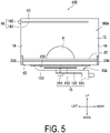
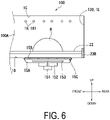
- FIG. 5 and FIG. 6 are diagrams illustrating a schematic cross section of the heating chamber 1 according to the present embodiment. More specifically, FIG. 5 illustrates a cross section of the heating chamber 1 taken along a plane orthogonal to the front-rear direction. FIG. 6 illustrates a cross section of the heating chamber 1 taken along a plane orthogonal to the left-right direction.
- the pull-out heating cooking apparatus 100 further includes a microwave supply unit 15 and a partitioning member 15B.
- the microwave supply unit 15 supplies microwaves to the heating cooking chamber 100A.
- the microwave supply unit 15 is positioned outside of the heating cooking chamber 100A via the bottom wall 1D.
- the microwave supply unit 15 includes a radiation chamber 15A, a magnetron 151, a waveguide 152, a rotary antenna 153, and an antenna motor 154.
- the magnetron 151 generates microwaves.
- the waveguide 152 propagates the microwaves generated by the magnetron 151 to the radiation chamber 15A.
- the radiation chamber 15A includes a radiation port 15C.
- the radiation port 15C has, for example, a square shape.
- the radiation port 15C is positioned below the heating cooking chamber 100A.
- the radiation port 15C is positioned at a substantially center portion of the bottom wall 1D.
- the rotary antenna 153 is accommodated in the radiation chamber 15A.
- the antenna motor 154 drives the rotary antenna 153.
- the rotary antenna 153 agitates microwaves and supplies the microwaves to the heating cooking chamber 100A through the radiation port 15C.
- the microwave supply unit 15 is provided below the heating cooking chamber 100A, and thus the object H to be heated can be irradiated with microwaves generated by the microwave supply unit 15 at a short distance. As a result, the object H to be heated can be efficiently heated.
- the partitioning member 15B covers the radiation port 15C.
- the partitioning member 15B need only have a shape that can cover the radiation port 15C.
- the partitioning member 15B is preferably a plate-like member. Further, when viewed from the vertical direction, the shape of the partitioning member 15B is, for example, a square shape.
- the material of the partitioning member 15B includes a ceramic or glass. As a result, because the material of the partitioning member 15B includes a ceramic or glass, the partitioning member 15B transmits microwaves. On the other hand, the materials of the radiation chamber 15A and the waveguide 152 include a metal.
- the pull-out heating cooking apparatus 100 further includes a grill unit 16.
- the grill unit 16 includes a heater 161 and an energization unit 162.
- the heater 161 is positioned in the heating cooking chamber 100A and heats the object H to be heated.
- the heater 161 is positioned at an upper portion in the heating cooking chamber 100A.
- the heater 161 has substantially a U shape when viewed from a vertical direction. In the present embodiment, three grill units 16 are disposed.
- the heater 161 is, for example, a sheathed heater.
- the energization unit 162 is positioned outside of the left wall 1B. The energization unit 162 energizes the heater 161.
- the energized heater 161 generates heat.
- the heater 161 is provided in an upper portion of the heating cooking chamber 100A, and the microwave supply unit 15 is provided below the heating cooking chamber 100A.
- the heater 161 does not inhibit an object H to be heated from being irradiated with microwaves and conducts heat generated by the heater 161 to an upper face of the object H to be heated, and thus the upper face of the object H to be heated can be efficiently heated.
- FIG. 7 is a block diagram illustrating a configuration of the pull-out heating cooking apparatus 100 according to the present embodiment.
- the pull-out heating cooking apparatus 100 has a "microwave heating mode” and a “grill heating mode” as heating cooking modes.
- the "microwave heating mode” is mainly a mode in which the object H to be heated is heated and cooked by radiating microwaves into the heating cooking chamber 100A.
- the "grill heating mode” is mainly a mode in which the object H to be heated is heated and cooked by conducting heat generated by the heater 161 to the object H to be heated.
- the control unit 5 controls a drive unit 133, the magnetron 151, the antenna motor 154, the energization unit 162, the drive motor 41, the operation panel 3, and the storage unit 6 by executing control programs stored in the storage unit 6.
- control unit 5 controls the driving of the microwave supply unit 15 and the driving of the grill unit 16. For example, in a case where the "microwave heating mode" is selected, the control unit 5 drives the magnetron 151 and the antenna motor 154. Further, in a case where the "grill heating mode” is selected, the control unit 5 energizes the energization unit 162.
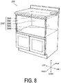
- FIG. 8 is a diagram illustrating an appearance of the cabinet 200 to which the pull-out heating cooking apparatus 100 according to the present embodiment is attached.
- the pull-out heating cooking apparatus 100 is installed in the cabinet 200 in built-in manner.
- the cabinet 200 includes an upper wall 200A, a lower wall 200B, a right wall 200C, a left wall 200D, and a rear wall 200E.
- the upper wall 200A, the lower wall 200B, the right wall 200C, the left wall 200D, and the rear wall 200E form an accommodation portion 200F.
- the accommodation portion 200F is a rectangular parallelepiped space in which the pull-out heating cooking apparatus 100 is attached.
- the present invention is useful in the field of a heating cooking apparatus, for example.
Landscapes
- Engineering & Computer Science (AREA)
- Physics & Mathematics (AREA)
- Electromagnetism (AREA)
- Chemical & Material Sciences (AREA)
- Combustion & Propulsion (AREA)
- Mechanical Engineering (AREA)
- General Engineering & Computer Science (AREA)
- Electric Ovens (AREA)
Applications Claiming Priority (2)
| Application Number | Priority Date | Filing Date | Title |
|---|---|---|---|
| JP2019141451 | 2019-07-31 | ||
| PCT/JP2020/028700 WO2021020343A1 (ja) | 2019-07-31 | 2020-07-27 | 加熱調理器 |
Publications (3)
| Publication Number | Publication Date |
|---|---|
| EP4006424A1 true EP4006424A1 (de) | 2022-06-01 |
| EP4006424A4 EP4006424A4 (de) | 2022-09-28 |
| EP4006424B1 EP4006424B1 (de) | 2025-10-01 |
Family
ID=74230383
Family Applications (1)
| Application Number | Title | Priority Date | Filing Date |
|---|---|---|---|
| EP20846465.1A Active EP4006424B1 (de) | 2019-07-31 | 2020-07-27 | Heizungsherd |
Country Status (6)
| Country | Link |
|---|---|
| US (1) | US12359822B2 (de) |
| EP (1) | EP4006424B1 (de) |
| JP (1) | JPWO2021020343A1 (de) |
| CN (1) | CN114144620B (de) |
| CA (1) | CA3149156A1 (de) |
| WO (1) | WO2021020343A1 (de) |
Family Cites Families (21)
| Publication number | Priority date | Publication date | Assignee | Title |
|---|---|---|---|---|
| CA1111505A (en) | 1977-08-01 | 1981-10-27 | Junzo Tanaka | Microwave oven having a radiation leak-proof drawer type door |
| US4335292A (en) * | 1979-05-09 | 1982-06-15 | Matsushita Electric Industrial Co., Ltd. | High frequency oven with drawer type door |
| JPS5942566Y2 (ja) * | 1979-08-15 | 1984-12-13 | 株式会社東芝 | 高周波加熱装置 |
| JPH07117246B2 (ja) * | 1991-07-31 | 1995-12-18 | 株式会社フジマック | バッチ型複合加熱装置 |
| FR2686400B3 (fr) | 1992-01-17 | 1994-04-01 | Moulinex Sa | Support recevant une preparation alimentaire surgelee et monte dans une machine de decongelation et de rechauffage. |
| DE10203606A1 (de) | 2002-01-30 | 2003-07-31 | Bsh Bosch Siemens Hausgeraete | Lichtwellenofen mit Schublade |
| KR20040061358A (ko) * | 2002-12-30 | 2004-07-07 | 엘지전자 주식회사 | 전자제품용 도어의 로고 인쇄구조 및 인쇄방법 |
| JP2006038300A (ja) | 2004-07-23 | 2006-02-09 | Sharp Corp | 引き出し式加熱調理器 |
| US7244916B2 (en) | 2004-01-14 | 2007-07-17 | Sharp Kabushiki Kaisha | Microwave heating and cooking apparatus including drawer body |
| JP2005315487A (ja) * | 2004-04-28 | 2005-11-10 | Matsushita Electric Ind Co Ltd | マイクロ波加熱方法及びその装置 |
| JP4404714B2 (ja) | 2004-07-23 | 2010-01-27 | シャープ株式会社 | 引き出し式加熱調理器 |
| JP2008257972A (ja) * | 2007-04-04 | 2008-10-23 | Matsushita Electric Ind Co Ltd | マイクロ波加熱装置 |
| JP2010133634A (ja) | 2008-12-04 | 2010-06-17 | Sharp Corp | 引出し型加熱調理器 |
| US8253084B2 (en) | 2008-11-28 | 2012-08-28 | Sharp Kabushiki Kaisha | Drawer type cooking device having turntable mechanism |
| JP2010181114A (ja) | 2009-02-06 | 2010-08-19 | Sharp Corp | 引出し型加熱調理器 |
| JP5593710B2 (ja) * | 2010-01-27 | 2014-09-24 | パナソニック株式会社 | マイクロ波加熱調理器 |
| JP5899426B2 (ja) * | 2011-05-12 | 2016-04-06 | パナソニックIpマネジメント株式会社 | 加熱調理器 |
| JP2014052152A (ja) * | 2012-09-10 | 2014-03-20 | Hitachi Appliances Inc | 加熱調理器 |
| JP6312294B2 (ja) | 2012-12-19 | 2018-04-18 | アイリスオーヤマ株式会社 | 加熱調理器 |
| CN203163010U (zh) | 2013-03-26 | 2013-08-28 | 广东美的微波电器制造有限公司 | 一种微波炉温度检测机构 |
| CA2940468C (en) * | 2014-08-29 | 2019-01-15 | Sharp Kabushiki Kaisha | Heating cooker |
-
2020
- 2020-07-27 CA CA3149156A patent/CA3149156A1/en active Pending
- 2020-07-27 EP EP20846465.1A patent/EP4006424B1/de active Active
- 2020-07-27 US US17/631,110 patent/US12359822B2/en active Active
- 2020-07-27 JP JP2021535328A patent/JPWO2021020343A1/ja active Pending
- 2020-07-27 WO PCT/JP2020/028700 patent/WO2021020343A1/ja not_active Ceased
- 2020-07-27 CN CN202080052979.0A patent/CN114144620B/zh active Active
Also Published As
| Publication number | Publication date |
|---|---|
| JPWO2021020343A1 (de) | 2021-02-04 |
| EP4006424B1 (de) | 2025-10-01 |
| WO2021020343A1 (ja) | 2021-02-04 |
| EP4006424A4 (de) | 2022-09-28 |
| CA3149156A1 (en) | 2021-02-04 |
| US20220205639A1 (en) | 2022-06-30 |
| CN114144620B (zh) | 2025-12-16 |
| CN114144620A (zh) | 2022-03-04 |
| US12359822B2 (en) | 2025-07-15 |
Similar Documents
| Publication | Publication Date | Title |
|---|---|---|
| US12359822B2 (en) | Heating cooking apparatus | |
| US12201240B2 (en) | Heating cooking apparatus | |
| US20230067149A1 (en) | Heating cooking apparatus | |
| US12104798B2 (en) | Heating cooking apparatus | |
| EP4279818A1 (de) | Gargerät | |
| US20220316710A1 (en) | Heating cooking apparatus | |
| US12144462B2 (en) | Heating cooking apparatus and built-in heating cooking system | |
| US12446121B2 (en) | Heating cooking apparatus | |
| US12516826B2 (en) | Heating cooking apparatus | |
| EP4299987A1 (de) | Thermischer kocher | |
| EP4299988A1 (de) | Kocher | |
| CA3201888A1 (en) | Heating cooking apparatus | |
| US12117182B2 (en) | Heating cooking apparatus | |
| EP4253842A1 (de) | Kocher mit heizung | |
| US12442535B2 (en) | Heating cooking apparatus | |
| EP4012263A1 (de) | Heiz- und kochvorrichtung |
Legal Events
| Date | Code | Title | Description |
|---|---|---|---|
| STAA | Information on the status of an ep patent application or granted ep patent |
Free format text: STATUS: THE INTERNATIONAL PUBLICATION HAS BEEN MADE |
|
| TPAC | Observations filed by third parties |
Free format text: ORIGINAL CODE: EPIDOSNTIPA |
|
| PUAI | Public reference made under article 153(3) epc to a published international application that has entered the european phase |
Free format text: ORIGINAL CODE: 0009012 |
|
| STAA | Information on the status of an ep patent application or granted ep patent |
Free format text: STATUS: REQUEST FOR EXAMINATION WAS MADE |
|
| 17P | Request for examination filed |
Effective date: 20220217 |
|
| AK | Designated contracting states |
Kind code of ref document: A1 Designated state(s): AL AT BE BG CH CY CZ DE DK EE ES FI FR GB GR HR HU IE IS IT LI LT LU LV MC MK MT NL NO PL PT RO RS SE SI SK SM TR |
|
| REG | Reference to a national code |
Ref country code: DE Ref legal event code: R079 Free format text: PREVIOUS MAIN CLASS: F24C0007020000 Ipc: H05B0006640000 Ref document number: 602020059850 Country of ref document: DE |
|
| A4 | Supplementary search report drawn up and despatched |
Effective date: 20220831 |
|
| RIC1 | Information provided on ipc code assigned before grant |
Ipc: F24C 15/16 20060101ALI20220825BHEP Ipc: F24C 15/02 20060101ALI20220825BHEP Ipc: F24C 7/02 20060101ALI20220825BHEP Ipc: H05B 6/72 20060101ALI20220825BHEP Ipc: H05B 6/64 20060101AFI20220825BHEP |
|
| DAV | Request for validation of the european patent (deleted) | ||
| DAX | Request for extension of the european patent (deleted) | ||
| GRAP | Despatch of communication of intention to grant a patent |
Free format text: ORIGINAL CODE: EPIDOSNIGR1 |
|
| STAA | Information on the status of an ep patent application or granted ep patent |
Free format text: STATUS: GRANT OF PATENT IS INTENDED |
|
| INTG | Intention to grant announced |
Effective date: 20250707 |
|
| GRAS | Grant fee paid |
Free format text: ORIGINAL CODE: EPIDOSNIGR3 |
|
| GRAA | (expected) grant |
Free format text: ORIGINAL CODE: 0009210 |
|
| STAA | Information on the status of an ep patent application or granted ep patent |
Free format text: STATUS: THE PATENT HAS BEEN GRANTED |
|
| AK | Designated contracting states |
Kind code of ref document: B1 Designated state(s): AL AT BE BG CH CY CZ DE DK EE ES FI FR GB GR HR HU IE IS IT LI LT LU LV MC MK MT NL NO PL PT RO RS SE SI SK SM TR |
|
| REG | Reference to a national code |
Ref country code: GB Ref legal event code: FG4D Ref country code: CH Ref legal event code: F10 Free format text: ST27 STATUS EVENT CODE: U-0-0-F10-F00 (AS PROVIDED BY THE NATIONAL OFFICE) Effective date: 20251001 |
|
| REG | Reference to a national code |
Ref country code: IE Ref legal event code: FG4D |
|
| REG | Reference to a national code |
Ref country code: DE Ref legal event code: R096 Ref document number: 602020059850 Country of ref document: DE |
|
| REG | Reference to a national code |
Ref country code: NL Ref legal event code: MP Effective date: 20251001 |
|
| REG | Reference to a national code |
Ref country code: AT Ref legal event code: MK05 Ref document number: 1843984 Country of ref document: AT Kind code of ref document: T Effective date: 20251001 |
|
| PG25 | Lapsed in a contracting state [announced via postgrant information from national office to epo] |
Ref country code: NL Free format text: LAPSE BECAUSE OF FAILURE TO SUBMIT A TRANSLATION OF THE DESCRIPTION OR TO PAY THE FEE WITHIN THE PRESCRIBED TIME-LIMIT Effective date: 20251001 |