EP4006447A1 - Absorptionsmaschine - Google Patents
Absorptionsmaschine Download PDFInfo
- Publication number
- EP4006447A1 EP4006447A1 EP21209991.5A EP21209991A EP4006447A1 EP 4006447 A1 EP4006447 A1 EP 4006447A1 EP 21209991 A EP21209991 A EP 21209991A EP 4006447 A1 EP4006447 A1 EP 4006447A1
- Authority
- EP
- European Patent Office
- Prior art keywords
- solution
- outlet
- inlet
- exchange device
- heat exchange
- Prior art date
- Legal status (The legal status is an assumption and is not a legal conclusion. Google has not performed a legal analysis and makes no representation as to the accuracy of the status listed.)
- Granted
Links
Images

Classifications
-
- F—MECHANICAL ENGINEERING; LIGHTING; HEATING; WEAPONS; BLASTING
- F25—REFRIGERATION OR COOLING; COMBINED HEATING AND REFRIGERATION SYSTEMS; HEAT PUMP SYSTEMS; MANUFACTURE OR STORAGE OF ICE; LIQUEFACTION SOLIDIFICATION OF GASES
- F25B—REFRIGERATION MACHINES, PLANTS OR SYSTEMS; COMBINED HEATING AND REFRIGERATION SYSTEMS; HEAT PUMP SYSTEMS
- F25B40/00—Subcoolers, desuperheaters or superheaters
-
- F—MECHANICAL ENGINEERING; LIGHTING; HEATING; WEAPONS; BLASTING
- F25—REFRIGERATION OR COOLING; COMBINED HEATING AND REFRIGERATION SYSTEMS; HEAT PUMP SYSTEMS; MANUFACTURE OR STORAGE OF ICE; LIQUEFACTION SOLIDIFICATION OF GASES
- F25B—REFRIGERATION MACHINES, PLANTS OR SYSTEMS; COMBINED HEATING AND REFRIGERATION SYSTEMS; HEAT PUMP SYSTEMS
- F25B15/00—Sorption machines, plants or systems, operating continuously, e.g. absorption type
- F25B15/02—Sorption machines, plants or systems, operating continuously, e.g. absorption type without inert gas
- F25B15/04—Sorption machines, plants or systems, operating continuously, e.g. absorption type without inert gas the refrigerant being ammonia evaporated from aqueous solution
-
- F—MECHANICAL ENGINEERING; LIGHTING; HEATING; WEAPONS; BLASTING
- F25—REFRIGERATION OR COOLING; COMBINED HEATING AND REFRIGERATION SYSTEMS; HEAT PUMP SYSTEMS; MANUFACTURE OR STORAGE OF ICE; LIQUEFACTION SOLIDIFICATION OF GASES
- F25B—REFRIGERATION MACHINES, PLANTS OR SYSTEMS; COMBINED HEATING AND REFRIGERATION SYSTEMS; HEAT PUMP SYSTEMS
- F25B2400/00—Component parts or details not otherwise provided for in this subclass
- F25B2400/23—Separators
-
- F—MECHANICAL ENGINEERING; LIGHTING; HEATING; WEAPONS; BLASTING
- F25—REFRIGERATION OR COOLING; COMBINED HEATING AND REFRIGERATION SYSTEMS; HEAT PUMP SYSTEMS; MANUFACTURE OR STORAGE OF ICE; LIQUEFACTION SOLIDIFICATION OF GASES
- F25B—REFRIGERATION MACHINES, PLANTS OR SYSTEMS; COMBINED HEATING AND REFRIGERATION SYSTEMS; HEAT PUMP SYSTEMS
- F25B25/00—Machines, plants or systems, using a combination of modes of operation covered by two or more of the groups F25B1/00 - F25B23/00
- F25B25/02—Compression-sorption machines, plants, or systems
-
- F—MECHANICAL ENGINEERING; LIGHTING; HEATING; WEAPONS; BLASTING
- F25—REFRIGERATION OR COOLING; COMBINED HEATING AND REFRIGERATION SYSTEMS; HEAT PUMP SYSTEMS; MANUFACTURE OR STORAGE OF ICE; LIQUEFACTION SOLIDIFICATION OF GASES
- F25B—REFRIGERATION MACHINES, PLANTS OR SYSTEMS; COMBINED HEATING AND REFRIGERATION SYSTEMS; HEAT PUMP SYSTEMS
- F25B37/00—Absorbers; Adsorbers
-
- Y—GENERAL TAGGING OF NEW TECHNOLOGICAL DEVELOPMENTS; GENERAL TAGGING OF CROSS-SECTIONAL TECHNOLOGIES SPANNING OVER SEVERAL SECTIONS OF THE IPC; TECHNICAL SUBJECTS COVERED BY FORMER USPC CROSS-REFERENCE ART COLLECTIONS [XRACs] AND DIGESTS
- Y02—TECHNOLOGIES OR APPLICATIONS FOR MITIGATION OR ADAPTATION AGAINST CLIMATE CHANGE
- Y02A—TECHNOLOGIES FOR ADAPTATION TO CLIMATE CHANGE
- Y02A30/00—Adapting or protecting infrastructure or their operation
- Y02A30/27—Relating to heating, ventilation or air conditioning [HVAC] technologies
-
- Y—GENERAL TAGGING OF NEW TECHNOLOGICAL DEVELOPMENTS; GENERAL TAGGING OF CROSS-SECTIONAL TECHNOLOGIES SPANNING OVER SEVERAL SECTIONS OF THE IPC; TECHNICAL SUBJECTS COVERED BY FORMER USPC CROSS-REFERENCE ART COLLECTIONS [XRACs] AND DIGESTS
- Y02—TECHNOLOGIES OR APPLICATIONS FOR MITIGATION OR ADAPTATION AGAINST CLIMATE CHANGE
- Y02B—CLIMATE CHANGE MITIGATION TECHNOLOGIES RELATED TO BUILDINGS, e.g. HOUSING, HOUSE APPLIANCES OR RELATED END-USER APPLICATIONS
- Y02B30/00—Energy efficient heating, ventilation or air conditioning [HVAC]
- Y02B30/62—Absorption based systems
Definitions
- the present invention relates to the field of absorption machines. It finds a particularly advantageous application in the field of ammonia-water absorption machines for the production of cold and/or heat.
- thermodynamics There are various technological solutions, many of which are based on the principles of thermodynamics.
- the water-ammonia absorption machine is an interesting technology, particularly thanks to its operating principle, which makes it possible to create a refrigeration or heat pump circuit using medium-high temperature heat as a source instead of electrical energy.
- this last source is precious and expensive, whereas the heat can be free (solar) or result as a waste from an industrial process.
- an absorption machine can easily be coupled with solar thermal systems, heat networks, industrial plants that require negative cold and even high-power turbo-gas electric generators.
- An object of the present invention is therefore to provide a simple and high-performance absorption machine capable of reconciling technical and economic requirements.
- the lean solution inlet of the heat generator being fluidically connected, preferably directly, to the lean solution outlet of the first separation bottle and to the condensed solution outlet of the second separation bottle,
- the first fluid comprises water and/or a solvent such as lithium nitrate or sodium thiocyanate
- the second fluid comprises ammonia or alcohol
- the lean solution has a first rate of mass concentration of the second fluid
- the condensed solution has a second rate of mass concentration of the second fluid
- the rich solution has a third rate of mass concentration of the second fluid
- the refrigerant solution has a fourth concentration rate by mass of the second fluid, the first concentration rate, the second concentration rate, the third concentration rate and the fourth concentration rate each being different from each other.
- the first rate of mass concentration of the second fluid is lower than the second rate of mass concentration of the second fluid, and the first rate of mass concentration of the second fluid and the third rate of mass concentration of the second fluid are lower than the fourth rate mass concentration of the second fluid.
- the inlet of the refrigerant solution of the condenser being fluidically connected, preferably directly, to the outlet of the refrigerant solution of the second separation bottle.
- the lean solution and the refrigerant solution being mixed at the inlet of the lean solution of the first heat exchange device.
- the machine in the first configuration, is configured to cool the fourth external heat transfer fluid.
- the first external heat transfer fluid and the third external heat transfer fluid form one and the same common external heat transfer fluid so that respectively the outlet of the first external heat transfer fluid from the absorber or the inlet of the first external heat transfer fluid of the absorber is fluidically connected, preferably directly, respectively to the inlet of the third external heat transfer fluid of the condenser or the output of the third external heat transfer fluid of the condenser, the machine then being configured to increase the temperature of said common external heat transfer fluid.
- At least one of the absorber, the first heat exchange device, the heat generator, the condenser, the evaporator comprises at least one plate heat exchanger.
- the absorber, the first heat exchange device, the heat generator, the condenser and the evaporator each comprise at least one plate heat exchanger.
- the plate heat exchanger is configured so that the fluids passing through it circulate in countercurrent relative to each other.
- the second heat exchange device comprises at least one plate heat exchanger.
- the lean solution and the rich solution circulate in countercurrent in the plate heat exchanger of the second heat exchange device.
- the third heat exchange device comprises at least one plate heat exchanger.
- the coolant solution and the rich solution circulate in countercurrent in the plate heat exchanger of the third heat exchange device.
- the secondary outlet of the rich solution of the third heat exchange device is fluidically connected, preferably directly, to the inlet of the rich solution of the second heat exchange device.
- the fourth heat exchange device comprises at least one plate heat exchanger.
- the lean solution leaving the condenser and the lean solution leaving the evaporator circulate in countercurrent in the plate heat exchanger of the fourth heat exchange device.
- the machine comprises at least one device for increasing the pressure of the refrigerant solution fluidly connected between the outlet of the refrigerant solution of the evaporator and the inlet of the lean solution of the first heat exchange device, so as to increase the pressure of the mixture of the lean solution with the cooling solution in the first heat exchange device, preferably in the absorber.
- the lean solution inlet of the first expansion valve is fluidically connected, preferably directly, to the lean solution outlet of the second heat exchange device.
- the inlet of the coolant solution of the second expansion valve is fluidically connected, preferably directly, to the main outlet of the coolant solution of the fourth heat exchange device.
- a fluidically connected to B or even “A fluidically connected to B” is synonymous with "A is in fluidic connection with B” and does not necessarily mean that there is no organ between A and B.
- these expressions refer to a fluidic connection between two elements, this connection possibly or not being direct, this means that it is possible that between a first device and a second device that are fluidly connected, a path of a fluid exists, which path may or may not include other devices.
- fluidically connected directly means a direct fluidic connection between two elements. This means that between a first device and a second device which are directly fluidically connected, no other organ is present, other than a conduit or several conduits.
- fluidically arranged means a positioning of a device in the path of a fluid.
- the present solution thus relates to an absorption machine capable of delivering heat and cold according to its configuration.
- the present invention makes it possible to carry out at least one thermodynamic absorption cycle of the GAX type while presenting advantages both in terms of performance but also of cost and size.
- the present solution uses a much more modular technology and overcomes the constraints known solutions.
- the present solution proposes to destructure the traditional columns of the generator and the absorber.
- the new structure makes it possible to achieve the same thermodynamic objectives, namely to produce the vapor of a concentrated solution called refrigerant necessary in the so-called refrigerating part of the machine.
- the heat exchangers involved are designed in a clever way and are arranged relative to each other in an optimized manner.
- an advantage of the present solution is that the absorption machine is able to present two configurations, one in heat pump and the other in refrigeration with interesting COPs. Each of these two configurations has an interesting coefficient of performance (COP).
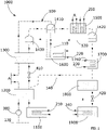
- the figure 1 represents the present machine 1000 in a configuration capable of generating cold, while the figure 2 , it represents a configuration capable of generating heat.
- the external heat transfer fluid of the absorber 1100 and of the condenser 1700 are different in the case of the refrigeration configuration, whereas they form advantageously one and the same external heat transfer fluid in the case of the heat pump configuration.
- the absorption machine comprises a circulating mixture 100 in a circuit.
- This circulating mixture 100 advantageously comprises at least a first fluid and a second fluid.
- This first fluid can advantageously be taken from at least: water, or a solvent such as lithium nitrate or sodium thiocyanate, or even a mixture of water and lithium nitrate.
- This second fluid can preferably be taken from at least: ammonia, or alcohol.
- the mass proportion of the first fluid is between 30% and 70%, preferably between 40% and 60%, and advantageously between 45% and 55%.
- the mass proportion of the second fluid is between 30% and 70%, preferably between 40% and 60%, and advantageously between 45% and 55%.
- the concentration of the second fluid in the circulating mixture 100 is variable during the circulation of said mixture 100 in the machine 1000.
- the mixture 100 in circulation advantageously has different levels of concentration of the second fluid in the first fluid depending on its circulation in said machine 1000.
- the mixture 100 in circulation can have a first level of concentration of the second fluid in the form of a lean solution 110.
- the lean solution 110 thus contains very little of the second fluid.
- the condensed solution 110 is a two-phase solution.
- lean solution 110 comprises a liquid part and a gaseous part.
- the liquid part substantially comprises the first fluid.
- the gaseous part largely comprises the second fluid.
- the lean solution 110 comprises a mass concentration of second fluid of less than 70%, preferably 60% and advantageously 50%.
- the circulating mixture 100 can also have a second level of concentration of the second fluid in the form of a condensed solution 120.
- This condensed solution 120 is preferably single-phase.
- This condensed solution 120 is advantageously liquid.
- the condensed solution 120 has a mass concentration of second fluid greater than the mass concentration of second fluid of the lean solution 110.
- the condensed solution 120 comprises a mass concentration of second fluid between 50% and 90%, preferably between 50% and 80%, and advantageously between 60% and 75%.
- the circulating mixture 100 may also have a third level of concentration of the second fluid in the form of a rich solution 130.
- the rich solution 130 is mainly liquid and largely comprises the first fluid and the second fluid.
- the rich solution 130 may have a gaseous part at one or more points of the circulation circuit of the machine 1000, preferably during its passage or at the outlet of the first heat exchange device 1200.
- the rich solution 130 comprises a second fluid mass concentration rate different from the second fluid mass concentration rate of the lean solution 110.
- the rich solution 130 comprises a second fluid mass concentration of between 30% and 80%, preferably between 40% and 70%, and advantageously between 45% and 65%.
- the circulating mixture 100 may also have a fourth level of concentration of the second fluid in the form of a cooling solution 140.
- the cooling solution 140 mainly comprises the second fluid.
- the cooling solution 140 can have a gaseous and/or liquid state.
- the cooling solution 140 has a mass concentration of second fluid greater than the mass concentration of second fluid of the rich solution 130.
- the cooling solution 140 comprises a mass concentration of second fluid greater than 90%, preferably 96% and advantageously 98%.
- a high temperature is considered to be the maximum temperature that the mixture 100 can reach during a thermodynamic cycle implemented by the machine 1000.
- this high temperature is greater than 130° C., advantageously 160°C.
- a high pressure is considered to be the maximum pressure that the mixture 100 can reach during a thermodynamic cycle implemented by the machine 1000.
- this high pressure is greater than 20 bar, advantageously 25 bar.
- a low temperature is considered to be the minimum temperature that the mixture 100 can reach during a thermodynamic cycle implemented by the machine 1000.
- this low temperature is lower than -15° C., advantageously at -35°C.
- a low pressure is considered to be the minimum pressure that the mixture 100 can reach during a thermodynamic cycle implemented by the machine 1000.
- the low pressure is less than 5 bar, advantageously less than 1 bar.
- the machine 1000 has a first configuration and a second configuration.
- the machine 1000 is configured to produce cold. This production of cold is preferably carried out by means of the reduction in the temperature of an external heat transfer fluid.
- the machine 1000 is configured to produce heat. This heat production is preferably carried out by means of increasing the temperature of an external heat transfer fluid.
- the present invention makes it possible to reduce the size of conventional absorption machines of the prior art. It also reduces manufacturing and installation costs. And finally, it makes it easier to maintain and replace parts.
- the inlet 1110 of the lean solution 110 of the absorber 1100 is fluidically connected, preferably directly, to an outlet 1220 of the lean solution 110 of the first heat exchange device 1200.
- the outlet 1120 of the rich solution 130 of the absorber 1100 is fluidically connected, preferably directly, to an inlet 1230 of the rich solution 130 of the first heat exchange device 120.
- a solution pump 300 can be arranged between the outlet 1120 of the rich solution 130 of the absorber 1100 and the inlet 1230 of the rich solution 130 of the first device for heat exchange 1200.
- the absorber 1100 is configured to cause the lean solution 110 and the first external heat transfer fluid 210 to thermally interact. This makes it possible to transform the lean solution 110 into a rich solution 130. lean solution 110. This decrease in temperature then makes it possible to increase the rate of mass concentration of the second fluid. The lean solution 110 then turns into a rich solution 130.
- the absorber 1100 makes it possible to generate an exothermic reaction by allowing the lean solution 110 to absorb the second fluid, thus being transformed into a rich solution 130.
- the exchange thermal between the lean solution 110 and the first external heat transfer fluid 210 is of the two-phase-liquid type.
- the lean solution 110 is in a two-phase state when it enters the absorber 1100.
- the quantity of the second fluid absorbed is directly linked to the absorption yield occurring in the absorber 1100.
- the rich solution 130 at the outlet of the absorber 1100 has a mass concentration of second fluid 1.5 times higher, preferably 3 times higher than the mass concentration of second fluid of the lean solution 110 at the inlet of the absorber 1100.
- the rich solution 130 is therefore colder than the lean solution 110 at the inlet, part of this heat having been transferred to the first external heat transfer fluid 210.
- the first external heat transfer fluid 210 enters the absorber 1100 at a temperature lower than that with which it emerges from the absorber 1100.
- the absorber 1100 comprises a plate heat exchanger.
- the machine 1000 comprises a pressure increase device capable of modifying the pressure of the mixture in circulation 100 in the absorber 1100 so as to increase the mass concentration of the second fluid of the rich solution 130 during the transformation of the lean solution 110 into a rich solution 130.
- This pressure increase device can for example be arranged at the inlet of the absorber 1100, even at the inlet of the first heat exchange device 1200, or even at the outlet of the fourth heat exchange device 1800, depending on the direction of circulation of the lean solution and/or of the cooling solution 140.
- This device The pressure increase could for example be a compressor or even an ejector, by way of non-limiting example.
- this pressure increase device is arranged between the secondary outlet 1840 of the refrigerant solution of the fourth heat exchange device 1800 and the inlet 1210 of the lean solution of the first heat exchange device 1200.
- This makes it possible to having a hotter solution at the inlet of the first heat exchange device 1200.
- This also makes it possible to have a higher pressure in the absorber 1100.
- This also makes it possible not to disturb the lean solution before its isenthalpic expansion phase produced by the first expansion valve 410. This then makes it possible to improve the COP.
- the plurality of separation bottles includes a first separation bottle, a second separation bottle, and a third separation bottle.
- the inlet 1230 of the rich solution 130 of the first heat exchange device is fluidically connected, preferably directly, to the outlet 1120 of the rich solution 130 of the absorber 1100.
- the weak solution 110 outlet 1220 is fluidically connected, preferably directly, to the weak solution 110 inlet 1110 of the absorber 1100.
- the inlet 1210 of the lean solution 110 is fluidically connected to an outlet 1432 of the lean solution 110 of a separation bottle 1430 of the plurality of separation bottles.
- a second heat exchange device 1300 is arranged between the inlet 1210 of the lean solution 110 of the first heat exchange device 1200 and the outlet 1432 of the lean solution 110 of said separation bottle 1430 of the plurality of separation bottles.
- a first expansion valve 410 of the plurality of expansion valves can be fluidically arranged between the inlet 1210 of the lean solution 110 of the first heat exchange device 1200 and the outlet 1432 of said bottle 1430 of the plurality of separation bottles relative to the circulation of the lean solution 110.
- said first expansion valve 410 of the plurality of expansion valves can be placed between the outlet 1320 of the lean solution 110 of the second heat exchange device 1300 and the inlet 1210 of the lean solution 110 of the first heat exchange device 1200 relative to the circulation of the lean solution 110.
- the inlet 1210 of the lean solution 110 of the first heat exchange device 1200 allows a mixture between the lean solution 110 and the cooling solution 140.
- the first heat exchange device 1200 is configured to cause the rich solution 130 to thermally interact with the lean solution 110. This thermal interaction is intended to modify the temperature of the rich solution 130, and advantageously of the lean solution 110.
- the first heat exchange device 1200 is configured to increase the temperature of the rich solution 130.
- the first heat exchange device 1200 is configured to decrease the temperature of the lean solution 110 .
- the first heat exchange device 1200 is configured to receive the rich solution 130, preferably at a first temperature and at a first pressure.
- This first temperature is preferably called cold, and advantageously is lower than the temperature of the lean solution 110 at the inlet of the first heat exchange device 1200.
- This first pressure is a high pressure, and advantageously is higher than the pressure of the solution lean 110 at the inlet of the first heat exchange device 1200.
- the first heat exchange device 1200 is advantageously configured to receive the lean solution 110 and preferably a mixture of the lean solution 110 and the cooling solution 140.
- the mixture of lean solution 110 and cooling solution 140 is a two-phase mixture comprising a liquid phase and a gaseous phase.
- This mixture is at a pressure lower than the pressure of the rich solution 130 entering the first heat exchange device.
- the rich solution 130 and the lean solution 110, and preferably said mixture move in the first heat exchange device against the current.
- the lean solution 110 and the cooling solution 140 are in co-current while the rich solution 130 is counter-current with respect to lean solution 110 and cooling solution 140.
- heat transfer from the lean solution 110 and the refrigerant solution 140 mixed to the rich solution 130 is possible via the use of a plate heat exchanger. It will be noted that in a clever way, the absorption generated by the meeting of the lean solution 110 with the refrigerated solution 140 is an exothermic reaction. This makes it possible to improve the heat transfer from the mixture of the lean solution 110 and the cooling solution 140 towards the rich solution 130.
- the rich solution 130 leaves the first heat exchange device 1200 at a temperature higher than that at which it entered the first heat exchange device 1200.
- the lean solution 110 mixed with the cooling solution 140 leaves the first heat exchange device 1200 at a temperature lower than the temperature at which it entered the first heat exchange device 1200.
- the first heat exchange device 1200 comprises a plate heat exchanger.
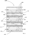
- the picture 3 schematically illustrates a plate heat exchanger of the first heat exchange device 1200.
- This plate exchanger comprises plates 160 separating two fluid circulation circuits, preferably in counter-current, in order to improve the heat exchanges 150.
- the rich solution 130 and its direction of circulation 131 in this plate heat exchanger we find the rich solution 130 and its direction of circulation 131 in this plate heat exchanger.
- the weak solution 110 and its direction of circulation 111 in this plate heat exchanger can be mixed with the cooling solution 140 before it enters the first heat exchange device 1200.
- a lean solution 110 exhibiting a two-phase state.
- Lean solution 110 then comprises a liquid phase 113 and a gaseous phase 112, said gaseous phase 112 being formed by the cooling solution 140 in the vapor state.
- heat exchanges 150 occur via the plates 160 of the plate exchanger. These heat exchanges 150 allow an increase in the rich solution making it partially diphasic and thus allowing the appearance of a gaseous phase 132 in the rich solution 130.
- the absorber 1100 and the first heat exchange device 1200 can form one and the same element of the machine.
- the first heat exchange device 1200 can be configured so that the lean solution 110 is in counter-current with the refrigerant solution 140 or semi-counter-current with the refrigerant solution 140. This makes it possible to improve absorption. This also makes it possible to improve the heat transfer between said mixture and the rich solution 130.
- the use of one or more plate heat exchangers configured so that the gaseous phase 112 and the liquid phase 113 circulate in counter-current relative to each other allows an improvement in the heat transfer. and absorption. Indeed, if the gaseous phase 112, that is to say the cooling solution 140, is injected in countercurrent with respect to the liquid phase 113, that is to say to the lean solution 110, then the absorption of the second fluid is improved, as is the heat transfer between the refrigerant solution 140 and the lean solution 110 and the rich solution 130.
- the plate heat exchanger can comprise one or more injectors at the bottom of each channel circulation of the lean solution 110, that is to say in the low pressure channels.
- the inlet 1411 of the rich solution 130 is fluidically connected, preferably directly, to the outlet 1240 of the rich solution 130 of the first heat exchange device 1200.
- the second heat exchange device 1300 is fluidly disposed between the first heat exchange device 1200 and the first separation bottle 1410 relative to the circulation of rich solution 130.
- the outlet 1340 of the rich solution 130 of the second separation device The heat exchanger 1300 is fluidically connected, preferably directly, to the inlet 1411 of the rich solution 130 of the first separation bottle 1410.
- the inlet 1413 of the cooling solution 140 of the first separation bottle 1410 is fluidically connected, preferably directly, to a third separation bottle 1430 of the plurality of separation bottles, preferably to the outlet 1433 of the cooling solution 140 from the third separation bottle 1430.
- the outlet 1412 of the lean solution 110 is fluidically connected, preferably directly, to the heat generator 1600, in particular to an inlet 1610 of the lean solution 110 of the heat generator 1600.
- the outlet 1414 of the cooling solution 140 is fluidically connected, preferably directly, to a second separation bottle 1420, in particular to an inlet 1421 of the cooling solution 140 of the second separation bottle 1420.
- the first separation bottle 1410 is configured so that when the rich solution 130 enters the first separation bottle 1410, the first separation bottle 1410 then separates the liquid part and the gaseous part of the rich solution 130. effect at this stage, the rich solution 130 is in a two-phase state.
- the gaseous part of the rich solution 130 is separated to feed the cooling solution 140, the remaining liquid part then forming the lean solution 110.
- the first separation bottle 1410 allows the recovery of heat from the cooling solution 140 incoming to poor solution 110 outgoing.
- the lean solution 110 at the outlet of the first separation bottle 1410 has a mass concentration of second fluid 10% lower, preferably 30% lower than the mass concentration of second fluid of the rich solution 130 at the inlet of the first separation bottle 1410.
- the third heat exchange device 1500 is fluidically arranged between the first separation bottle 1410 and the second separation bottle 1420 relative to the cooling solution 140. More particularly, the outlet 1414 of the cooling solution 140 of the first bottle 1414 is fluidically connected, preferably directly, to an inlet 1510 of the cooling solution 140 of the third heat exchange device 1500. And the inlet 1421 of the cooling solution 140 of the second separation bottle 1420 is preferably fluidically connected, preferably directly, to an outlet 1520 of the cooling solution 140 of the third heat exchange device 1500.
- the first separation bottle 1410 is configured to thermally interact the rich solution 130 with the cooling solution 140 of so as to transform the rich solution 130 into a lean solution 110, preferably so as to reduce the mass concentration rate of the second fluid in the rich solution 130 so as to obtain the lean solution 110.
- the use of one or more separation cylinders makes it possible to free oneself from conventional use of the column of the generator called GAX used in the prior art and having a complexity of assembly and a consequent bulk.
- the rich solution 130 is in a two-phase state when it enters the first separation bottle 1410, ie it comprises a liquid portion and a gaseous portion.
- the rich solution 130 enters the first separation bottle 1410, it is mixed with a saturated vapor present with the cooling solution 140 at the outlet of the third separation bottle 1430.
- the cooling solution 140 is preferably at high temperature at the outlet of the third separation bottle 1430.
- saturated part of the heat of this steam, called saturated, is transferred to the rich solution 130.
- This mixture causes evaporation.
- This mixture then causes the separation of the rich solution 130 into two phases resulting in the lean solution 110 which is preferably two-phase.
- the first separation bottle 1410 enables the column of the generator present in the solutions of the prior art to be eliminated.
- the first separation bottle comprises a pressurized reservoir which allows good phase separation and/or effective heat exchange between the different solutions.
- the inlet 1421 of the cooling solution 140 is fluidically connected, preferably directly, to the outlet 1414 of the cooling solution 140 of the first separation bottle 1410.
- the third heat exchange device 1500 can be arranged fluidically between the outlet 14141 of the cooling solution 140 of the first separation bottle 1410 and the inlet 1421 of the cooling solution 140 of the second separation bottle 1420.
- the outlet 1422 of the refrigerant solution 140 is fluidically connected, preferably directly, to the condenser 1700, in particular to an inlet 1710 of the refrigerant solution 140 of the condenser 1700.
- the outlet 1423 of the condensed solution 120 is fluidically connected, preferably directly, to the outlet 1412 of the lean solution 110 of the first separation bottle 1410 or to the inlet 1610 of the lean solution 110 of the generator of heat 1600 so as to be mixed with the lean solution 110, preferably before entering the heat generator 1600.
- the second separation bottle 1420 is configured to extract at least part of the condensed solution 120 from the refrigerant solution 140.
- this second separation bottle 1420 is configured to split the very rich vapor in the second fluid from the liquid part, this liquid part then forming the refrigerant solution 140.
- the second separation bottle 1420 is preferably configured to separate the vapor rich in first fluid from the refrigerant solution 140. This vapor then forms the condensed solution 120.
- the condensed solution 120 is more concentrated than the lean solution 110.
- the outlet 1423 of the cooling solution 140 of the second separation bottle is fluidically connected, preferably directly, to the first separation bottle 1410, preferably to an inlet of the cooling solution 140 of the first bottle separation 1410. This allows the recovery of at least part of the first fluid. This allows for improved performance.
- the inlet 1431 of the lean solution 110 of the third separation bottle 1430 is fluidically connected, preferably directly, to the outlet 1620 of the lean solution 110 of the heat generator 1600.
- the outlet 1432 of the lean solution 110 of the third separation bottle 1430 is fluidically connected, preferably directly, to the inlet 1210 of the lean solution 110 of the first heat exchange device 1200.
- the second heat exchange device 1300 is fluidically disposed between the outlet 1432 of the lean solution 110 of the third bottle of separation 1430 and the first heat exchange device 1200.
- the second heat exchange device 1300 is fluidically disposed between the outlet 1432 of the lean solution 110 of the third separation bottle 1430 and the first expansion valve 410 .
- the outlet 1433 of the refrigerant solution 140 of the third separation cylinder 1430 is fluidically connected, preferably directly, to the inlet 1413 of the refrigerant solution 140 of the first separation cylinder 1410.
- the third separation bottle 1430 is configured to extract at least part of the refrigerant solution 140 from the lean solution 110, preferably once it has left the heat generator 1600.
- the third separation bottle 1430 allows the separation of the vapor phase and the liquid phase of the lean solution 110 leaving the heat generator 1600. Indeed, at the outlet of the heat generator 1600, the lean solution 110 is at high pressure and at high temperature, that is to say at a temperature and at a pressure higher than that of the lean solution 110 entering the heat generator 1600.
- this second separation bottle 1420 makes it possible to separate the vapor and liquid phases at the output of the heat generator 1600.
- this third separation bottle 1430 at the output of the heat generator heat 1600 makes it possible to do away with the traditional and cumbersome column of heat generators of the prior art.
- this third separation bottle 1430 comprises a pressurized tank.
- the third separation cylinder 1430 is configured to operate at high pressure and high temperature.
- the first separation bottle 1410 and the third separation bottle 1430 form one and the same separation bottle ensuring on its own the functions of the first separation bottle 1410 and of the third separation bottle 1430. This makes it possible to simplify the implementation of the present invention. And it also reduces manufacturing and/or installation costs.
- the weak solution 110 inlet 1610 of the heat generator 1600 is fluidly connected, preferably directly, to the weak solution 110 outlet 1412 of the first separation bottle 1410.
- the weak solution inlet 1610 of the the poor solution 110 of the heat generator 1600 is also fluidically connected, preferably directly, to the outlet 1423 of the condensed solution 120 of the second separation bottle 1420.
- the outlet 1620 of the lean solution 110 of the heat generator is fluidically connected, preferably directly, to the inlet 1431 of the lean solution 110 of the third separation bottle 1430.
- the lean solution 110 and the condensed solution 120 are mixed at the inlet 1610 of the lean solution 110 of the heat generator 1600.
- the heat generator 1600 is configured to cause the lean solution 110 and the second external heat transfer fluid 220 to thermally interact, preferably so as to increase the temperature of the lean solution 110.
- This increase in the temperature of the lean solution 110 is intended to cause the lean solution 110 to reach the high temperature.
- the heat generator 1600 comprises a plate heat exchanger.
- This plate heat exchanger is configured to operate in counter-current. That is to say that the lean solution 110 circulates in one direction in the plate heat exchanger and that the second external heat transfer fluid 220 circulates in the opposite direction. This counter-current flow increases the efficiency of heat transfer.
- the heat generator 1600 is configured to operate at high pressure, that is to say at a pressure greater than 30 bar.
- the heat generator 1600 is advantageously configured to heat the lean solution 110 at high temperature, that is to say at a temperature up to 200°C.
- the main inlet 1710 of the refrigerant solution 140 of the condenser 1700 is fluidically connected, preferably directly, to the outlet 1422 of the refrigerant solution 140 of the second separation bottle 1420.
- the main outlet 1720 of the refrigerant solution 140 of the condenser 1700 is fluidically connected, preferably directly, to the main inlet 1910 of the evaporator 1900.
- a fourth heat exchange device 1800 is arranged fluidically between the main outlet 1720 of the refrigerant solution 140 of the condenser 1700 and the main inlet 1910 of the evaporator 1900.
- the condenser 1700 is configured to thermally interact the cooling solution 140 and the third external heat transfer fluid 230 so as to modify the temperature of the cooling solution 140, preferably so as to decrease the temperature of the cooling solution 140.
- condenser 1700 includes a plate heat exchanger.
- the condenser 1700 is configured to use the third external heat transfer fluid 230 so as to cool the refrigerant solution 140 passing through it. This then makes it possible to partially liquefy at least part of the cooling solution 140.
- the condenser 1700 makes it possible to set the value of the high pressure. Indeed, the high pressure is advantageously dependent on the minimum temperature to which the cooling solution 140 is cooled.
- the main inlet 1910 of the refrigerant solution 140 of the evaporator 1900 is fluidically connected, preferably directly, to the main outlet 1720 of the refrigerant solution 140 of the condenser 1700.
- the fourth device for The heat exchanger 1800 is arranged fluidically between the main outlet 1720 of the refrigerant solution 140 of the condenser 1700 and the main inlet 1910 of the refrigerant solution 140 of the evaporator 1900.
- the main outlet 1920 of the refrigerant solution 140 of the evaporator 1900 is fluidically connected, preferably directly, to the inlet 1210 of the lean solution 110 of the first heat exchange device 1200.
- the fourth heat exchange device 1800 is arranged fluidically between the main outlet 1920 of the refrigerant solution 140 of the evaporator 1900 and the inlet 1210 of the lean solution 110 of the first heat exchange device 1200.
- the evaporator 1900 is configured to cause the cooling solution 140 and the fourth external heat transfer fluid 240 to thermally interact, in such a way as to modify the temperature of the fourth external heat transfer fluid 240.
- This temperature modification is possible via the evaporation of a part at less of the cooling solution 140. This then makes it possible to reduce the temperature of the fourth external heat transfer fluid 240 via the evaporation of at least part of the cooling solution 140.
- the lean solution 110 coming from the third separation bottle 1430 and the refrigerant solution 140 coming from the evaporator 1900 are mixed upstream or at the inlet 1210 of the lean solution 110 of the first heat exchange 1200.
- the second heat exchange device 1300 is fluidly disposed between the third separation bottle 1430 and the first heat exchange device 1200 relative to the circulation of the lean solution 110.
- the second separation device heat exchanger 1300 is arranged fluidically between the outlet 1432 of the lean solution 110 of the third separation bottle 1430 and the inlet 1210 of the lean solution 110 of the first heat exchange device 1200 relative to the circulation of the lean solution 110 .
- the second heat exchange device 1300 is fluidly disposed between the first heat exchange device 1200 and the first separation bottle 1410 relative to the circulation of the rich solution 130.
- the second device heat exchanger 1300 is arranged fluidically between the outlet 1240 of the rich solution 130 of the first heat exchange device 1200 and the inlet 1411 of the rich solution 130 of the first separation bottle 1410 relative to the circulation of the rich solution 130 .
- the inlet 1330 of the rich solution 130 of the second heat exchange device 1300 is fluidically connected, preferably directly, with the outlet 1240 of the rich solution 130 of the first heat exchange device 1200, advantageously with the outlet secondary 1540 of the rich solution 130 of the third heat exchange device 1500 as described below.
- the outlet 1340 of the rich solution 130 of the second heat exchange device 1300 is fluidically connected, preferably directly, to the inlet 1411 of the rich solution 130 of the first separation bottle 1410.
- the inlet 1310 of the lean solution 110 of the second heat exchange device 1300 is fluidically connected, preferably directly, with the outlet 1432 of the lean solution 110 of the third separation bottle 1430.
- the outlet 1320 of the lean solution 110 of the second heat exchange device 1300 is fluidically connected, preferably directly, with the inlet 1210 of the lean solution 110 of the first heat exchange device 1200.
- the first expansion valve 410 is fluidically disposed between the outlet 1320 of the lean solution 110 of the second heat exchange device 1300 and the inlet 1210 of the lean solution 110 of the first heat exchange device 1200.
- the second heat exchange device 1300 is configured to thermally interact the rich solution 130 with the lean solution 110.
- the second heat exchange device 1300 is configured to increase the temperature of the rich solution 130 and to decrease the temperature of the lean solution 110.
- the second heat exchange device 1300 allows heat transfer between the lean solution 110 which is at high temperature and the rich solution 130 which is at a temperature below the high temperature.
- the rich solution 130 then becomes partly at least two-phase throughout its passage through the second heat exchange device 1300.
- the fluids circulating in the second heat exchange device 1300 are in countercurrent.
- the rich solution 130 and the lean solution 110 are preferably at the same pressure.
- the second heat exchange device 1300 comprises at least one plate heat exchanger. According to one embodiment, the second heat exchange device 1300 comprises at least one plate heat exchanger.
- the lean solution 110 before it enters the heat generator 1600, can be preheated by the lean solution 110 leaving the third separation bottle 1430, before it passes through the second heat exchange device 1300
- this heat exchange then occurs at a high temperature and has advantages in terms of irreversibility.
- the temperatures involved in this heat exchange are both high, and relatively close to each other. This makes it possible to use the temperatures at the exit of this heat exchange to carry out other exchanges thermal.
- the coldest temperature remains sufficiently hot to be cooled at least once again during a subsequent heat exchange.
- the third heat exchange device 1500 is fluidly disposed between the first heat exchange device 1200 and the first separation bottle 1410 relative to the circulation of the rich solution 130.
- the third device heat exchanger 1500 is arranged fluidically between the outlet 1240 of the rich solution 130 of the first heat exchange device 1200 and the inlet 1411 of the rich solution 130 of the first separation bottle 1410 relative to the circulation of the rich solution 130
- the third heat exchange device 1500 is arranged fluidically between the first heat exchange device 1200 and the second heat exchange device 1300 with respect to the circulation of the rich solution 130.
- the third heat exchange device 1500 is fluidically arranged between the outlet 1240 of the rich solution 130 of the first device heat exchange device 1200 and the inlet 1330 of the rich solution 130 of the second heat exchange device 1300 relative to the circulation of the rich solution 130.
- the third heat exchange device 1300 is fluidically arranged between the first separation bottle 1410 and the second separation bottle 1420 with respect to the circulation of the cooling solution 140.
- the third heat exchange device 1500 is arranged between the outlet 1414 of the cooling solution 140 of the first separation bottle 1410 and the inlet 1421 of the cooling solution 140 of the second separation bottle 1420 relative to the circulation of the cooling solution 140.
- the main inlet 1510 of the cooling solution 140 of the third heat exchange device 1500 is fluidically connected, preferably directly, to the outlet 1414 of the cooling solution 140 of the first separation bottle 1410.
- the main outlet 1520 of the cooling solution 140 of the third heat exchange device 1500 is fluidically connected, preferably directly, to the inlet 1421 of the cooling solution 140 of the second separation bottle 1420.
- the secondary inlet 1530 of the rich solution 130 of the third heat exchange device 1500 is fluidically connected, preferably directly, to the outlet 1240 of the rich solution 130 of the first heat exchange device 1200.
- the secondary outlet 1540 of the rich solution 130 of the third heat exchange device 1500 is fluidically connected, preferably directly, to the inlet 1411 of the rich solution 130 of the first separation bottle 1410.
- the secondary outlet 1540 of the rich solution 130 of the third heat exchange device 1500 is fluidically connected, preferably directly, to the inlet 1330 of the rich solution 130 of the second heat exchange device 1300.
- the third heat exchange device 1500 is configured to cause the cooling solution 140 to thermally interact with the rich solution 130. This then makes it possible to increase the temperature of the rich solution 130 while cooling the cooling solution 140.
- the third heat exchange device 1500 is configured to cause the cooling solution 140 to thermally interact with the fifth external heat transfer fluid 250. This then makes it possible to cool the cooling solution 140.
- the third heat exchange device 1500 is configured to enrich the liquid part of the refrigerant solution 140 by mainly cooling the gaseous part of the refrigerant solution 140.
- the third heat exchange device 1500 comprises a first part and a second part.
- the first part comprises at least a first heat exchanger configured to cool the refrigerant solution 140 from the rich solution 130.
- This first heat exchanger is preferably a plate heat exchanger.
- the second part comprises at least one second heat exchanger configured to cool the refrigerant solution 140 from the fifth external heat transfer fluid 250, preferably at room temperature.
- This second heat exchanger 1500 is preferably a plate heat exchanger. This makes it possible to recover heat at the level of the cooling solution 140 between the first separation bottle 1410 and the second separation bottle 1420. This makes it possible to heat the rich solution 130 between the first device heat exchanger 1200 and the first separation bottle 1410, preferably between the first heat exchange device 1200 and the second heat exchange device 1300.
- the third heat exchange device 1500 comprises at least one plate heat exchanger, preferably two plate heat exchangers.
- the second part of the third heat exchange device 1500 can be eliminated, in particular, if the machine 1000 is configured so that the temperature at the outlet of the third heat exchange device is higher. This makes it possible to reduce the manufacturing costs of the Machine 1000 according to the present invention.
- the fourth heat exchange device 1800 is arranged fluidically between the condenser 1700 and the evaporator 1900 with respect to the circulation of the refrigerant solution 140.
- the fourth heat exchange device 1800 is arranged fluidically between the outlet 1720 of the refrigerant solution 140 of the condenser 1700 and the inlet 1910 of the refrigerant solution 140 of the evaporator 1900.
- a second expansion valve 420 is fluidically disposed between the fourth heat exchange device 1800 and the evaporator 1900.
- the second expansion valve is fluidically disposed between the outlet 1720 of the solution refrigerant 140 of the condenser 1700 and the inlet 1910 of the refrigerant solution 140 of the evaporator 1900.
- the fourth heat exchange device 1800 is fluidly arranged between the evaporator 1900 and the first heat exchange device 1200 with respect to the circulation of the cooling solution 140.
- the fourth heat exchange device thermal 1800 is fluidically disposed between the outlet 1920 of the cooling solution 140 of the evaporator 1900 and the inlet 1210 of the cooling solution 140 of the first heat exchange device 1200.
- the main inlet 1810 of the cooling solution 140 of the fourth heat exchange device 1800 is fluidically connected, preferably directly, at the main outlet 1720 of the refrigerant solution 140 of the condenser 1700.
- the main outlet 1820 of the refrigerant solution 140 of the fourth heat exchange device 1800 is fluidically connected, preferably directly, to the inlet 1910 of the refrigerant solution 140 of the evaporator 1900.
- the main outlet 1820 of the coolant solution 140 of the fourth heat exchange device 1800 is fluidically connected, preferably directly, to the inlet 421 of the coolant solution 140 of the second expansion valve 420.
- the outlet 422 of the second expansion valve 420 is fluidically connected, preferably directly, to the inlet 1910 of the refrigerant solution 140 of the evaporator 1900.
- the secondary inlet 1830 of the refrigerant solution 140 of the fourth heat exchange device 1800 is fluidically connected, preferably directly, with the outlet 1920 of the refrigerant solution 140 of the evaporator 1900.
- the secondary outlet 1840 of the cooling solution 140 of the fourth heat exchange device 1800 is fluidically connected, preferably directly, to the inlet 1210 of the lean solution 110 of the first heat exchange device 1200.
- the fourth heat exchange device 1800 is configured to cause the cooling solution 140 to thermally interact before it enters the evaporator 1900 with the cooling solution 140 after it leaves the evaporator 1900.
- the fourth heat exchange device 1800 is configured to cool the refrigerant solution 140 before it enters the evaporator 1900, preferably before it undergoes expansion, preferably isenthalpic, via the second expansion valve 420. This makes it possible to optimize, preferably to maximize, the thermal drop of the refrigerant solution 140 before it enters the evaporator 1900.
- the fourth heat exchange device 1800 makes it possible to improve the evaporation of the cooling solution 140 before it enters the absorber 1100, preferably the first thermal device 1200.
- the fourth heat exchange device 1800 comprises at least one plate heat exchanger, preferably only plate heat exchangers.
- the plurality of expansion valves comprises at least a first expansion valve 410 and a second expansion valve 420 as previously described.
- the first expansion valve 410 is fluidically placed between the third separation bottle 1430 and the first heat exchange device 1200 with respect to the circulation of the lean solution 110.
- the first expansion valve expansion valve 410 is fluidly disposed between the second thermal device 1300 and the first heat exchange device 1200 relative to the circulation of the lean solution 110.
- the inlet 412 of the lean solution 110 of the first expansion valve 410 is fluidically connected, preferably directly, to the outlet 1320 of the lean solution 110 of the second heat exchange device 1300.
- the outlet 411 of the lean solution 110 of the first expansion valve 410 is fluidically connected, preferably directly, at the inlet 1210 of the lean solution 110 of the first heat exchange device 1200.
- the first expansion valve nsion 410 is configured to modify the temperature of the weak solution 110, preferably to modify the temperature of the weak solution 110 by an isenthalpic expansion. This allows the poor solution 110 to be at low pressure when it arrives at the first heat exchange device 1200 and preferably at the absorber 1100.
- the second expansion valve 420 is fluidically placed between the condenser 1700 and the evaporator 1900 with respect to the circulation of the lean solution 110.
- the second expansion valve 420 is fluidically placed between the fourth heat exchange device 1800 and the evaporator 1900 with respect to the circulation of the lean solution 110.
- the inlet 421 of the lean solution 110 of the second expansion valve 420 is fluidically connected, preferably directly, to the weak solution 110 outlet 1820 of the fourth heat exchange device 1800.
- the weak solution 110 outlet 422 of the second expansion valve 420 is fluidically connected, preferably directly, to the inlet 1910 of the the lean solution 110 from the evaporator 1900.
- the second expansion valve 420 is configured to make it possible to modify the temperature of the lean solution 110 , preferably to allow the lean solution 110 to reach a predetermined evaporation temperature before the lean solution 110 enters the evaporator 1900.
- the second expansion valve 420 causes the lean solution 110 to undergo a isenthalpic relaxation.
- the first expansion valve 410 is configured to produce isenthalpic expansion.
- the first expansion valve 410 is configured to generate an isothermal expansion. This makes it possible to improve the thermodynamic effect or effects of the first heat exchange device 1200 on the mixture 100 in circulation.
- the solution pump 300 is arranged fluidically between the absorber 1100 and the first heat exchange device 1200 relative to the circulation of the rich solution 130.
- the inlet 310 of the rich solution 130 of the solution pump 300 is fluidically connected, preferably directly, to the output 1120 of the rich solution 130 of the absorber 1100.
- the output 320 of the rich solution 130 of the solution pump 300 is fluidically connected, preferably directly, at the inlet 1230 of the rich solution 130 of the first heat exchange device 1200.
- the solution pump 300 is configured to modify the pressure of the rich solution 130, preferably to increase the pressure of the rich solution 130.
- the solution pump 300 ensures the circulation of the mixture in the machine 1000.
- the solution pump 300 brings the rich solution 130 preferably at high pressure.
- the present invention makes it possible to carry out a thermodynamic cycle of the GAX type with preferably only plate heat exchangers, while maintaining or even improving the performance of this type of machine but at the same time reducing the costs, the size and the maintenance difficulties.
- the present invention makes it possible to generate cold or heat depending on its operational configuration. This then makes it possible to increase the possible applications and consequently its economic interest.
- the destructuring of the old and cumbersome columns of the absorber and the heat generator allows the clever use of new thermodynamic devices arranged and configured in an ingenious way. This makes it possible to reduce the vertical development of the components and this allows a better distribution of the components in space.
- the present invention allows a better compactness of the machine, for example via the use of separation bottles and/or via the use of one or more plate heat exchangers.
- the present invention makes assembly and maintenance of the machine simpler.
Landscapes
- Engineering & Computer Science (AREA)
- Physics & Mathematics (AREA)
- Mechanical Engineering (AREA)
- Thermal Sciences (AREA)
- General Engineering & Computer Science (AREA)
- Sorption Type Refrigeration Machines (AREA)
Applications Claiming Priority (1)
| Application Number | Priority Date | Filing Date | Title |
|---|---|---|---|
| FR2012308A FR3116890B1 (fr) | 2020-11-27 | 2020-11-27 | Machine à absorption |
Publications (2)
| Publication Number | Publication Date |
|---|---|
| EP4006447A1 true EP4006447A1 (de) | 2022-06-01 |
| EP4006447B1 EP4006447B1 (de) | 2023-10-25 |
Family
ID=74045968
Family Applications (1)
| Application Number | Title | Priority Date | Filing Date |
|---|---|---|---|
| EP21209991.5A Active EP4006447B1 (de) | 2020-11-27 | 2021-11-23 | Absorptionsmaschine |
Country Status (2)
| Country | Link |
|---|---|
| EP (1) | EP4006447B1 (de) |
| FR (1) | FR3116890B1 (de) |
Citations (3)
| Publication number | Priority date | Publication date | Assignee | Title |
|---|---|---|---|---|
| EP3236178A1 (de) * | 2016-04-22 | 2017-10-25 | AGO AG Energie + Anlagen | Sorptionswärmepumpe und sorptionskreisprozess |
| CN106091474B (zh) * | 2016-06-17 | 2018-09-18 | 珠海格力电器股份有限公司 | 氨水吸收-压缩式制冷/热泵系统及换热方法 |
| EP3540334A1 (de) * | 2018-03-15 | 2019-09-18 | AGO AG Energie + Anlagen | Wärmetransformator und wärmetransformationsprozess |
-
2020
- 2020-11-27 FR FR2012308A patent/FR3116890B1/fr active Active
-
2021
- 2021-11-23 EP EP21209991.5A patent/EP4006447B1/de active Active
Patent Citations (3)
| Publication number | Priority date | Publication date | Assignee | Title |
|---|---|---|---|---|
| EP3236178A1 (de) * | 2016-04-22 | 2017-10-25 | AGO AG Energie + Anlagen | Sorptionswärmepumpe und sorptionskreisprozess |
| CN106091474B (zh) * | 2016-06-17 | 2018-09-18 | 珠海格力电器股份有限公司 | 氨水吸收-压缩式制冷/热泵系统及换热方法 |
| EP3540334A1 (de) * | 2018-03-15 | 2019-09-18 | AGO AG Energie + Anlagen | Wärmetransformator und wärmetransformationsprozess |
Also Published As
| Publication number | Publication date |
|---|---|
| FR3116890B1 (fr) | 2022-11-18 |
| EP4006447B1 (de) | 2023-10-25 |
| FR3116890A1 (fr) | 2022-06-03 |
Similar Documents
| Publication | Publication Date | Title |
|---|---|---|
| EP3732743B1 (de) | Energieerzeugungsanlage mit kopplung einer brennstoffzelle und eines reversiblen thermodynamischen systems | |
| FR2575787A1 (fr) | Procede de production d'energie mecanique | |
| EP3510257A1 (de) | Mechanisches system zur erzeugung mechanischer energie aus flüssigem stickstoff und entsprechendes verfahren | |
| FR3112198A1 (fr) | Installation et procédé de réfrigération d’hydrogène | |
| EP4092356B1 (de) | Absorptionsmaschine mit spiralförmigen plattenwärmetauschern | |
| EP4006447B1 (de) | Absorptionsmaschine | |
| EP4256185A1 (de) | System und verfahren zur speicherung und rückgewinnung von energie unter verwendung von druckgas mit rückgewinnung von flüssigkeit | |
| BE903196A (fr) | Procede de production d'energie | |
| EP4350129B1 (de) | System zur energieerzeugung mit einem organischen rankine-zyklus und integriertem absorptionszyklus | |
| FR2807826A1 (fr) | Echangeur vaporisateur-condenseur du type a bain | |
| FR3068442A1 (fr) | Dispositif de refroidissement combine a une production de vapeur | |
| FR2943125A1 (fr) | Procede de liquefaction de gaz naturel a cycle combine | |
| EP4116640B1 (de) | System zur erzeugung von kälte und strom aus einer thermischen quelle mit niedriger temperatur, das eine regelung des verhältnisses zwischen kälte- und stromerzeugung ermöglicht | |
| EP3390938B1 (de) | Hybridverfahren zur verflüssigung eines brenngases und anlage zur implementierung davon | |
| WO2022268830A1 (fr) | Procede de stockage et de recuperation d'energie avec stockage de chaleur indirect a la compression | |
| FR3029612A1 (fr) | Systeme de liquefaction de gaz a machine a absorption et pompe a chaleur stirling | |
| FR3117164A1 (fr) | Système et procédé de stockage et de récupération d’énergie par gaz comprimé avec cycle de Rankine | |
| FR2858830A1 (fr) | Procede pour augmenter la capacite et l'efficacite d'installations gazieres du type comprenant une turbine a gaz | |
| FR3117163A1 (fr) | procédé de stockage et de récupération d’énergie comprenant une turbine à gaz pour réchauffer le gaz comprimé à la détente | |
| FR3152176A1 (fr) | Transformateur de chaleur à absorption optimisé par éjecteur | |
| WO2022263754A1 (fr) | Systeme de recuperation d'energie de compression d'un gaz, liquefacteur comprenant un tel systeme et procede de recuperation d'energie de compression d'un gaz | |
| FR3117166A1 (fr) | Système et procédé de stockage et de récupération d’énergie par gaz comprimé avec réchauffage de liquide | |
| FR3045726A1 (fr) | Dispositifs et procede d'extraction et de valorisation de l'energie de detente d'un gaz sous pression non chauffe | |
| FR2944095A1 (fr) | Procede de liquefaction de gaz naturel utilisant des turbines a gaz a basse temperature d'echappement | |
| FR3029208A1 (fr) | Systeme de refroidissement et de chauffage pour la thermovinification |
Legal Events
| Date | Code | Title | Description |
|---|---|---|---|
| PUAI | Public reference made under article 153(3) epc to a published international application that has entered the european phase |
Free format text: ORIGINAL CODE: 0009012 |
|
| STAA | Information on the status of an ep patent application or granted ep patent |
Free format text: STATUS: REQUEST FOR EXAMINATION WAS MADE |
|
| 17P | Request for examination filed |
Effective date: 20211123 |
|
| AK | Designated contracting states |
Kind code of ref document: A1 Designated state(s): AL AT BE BG CH CY CZ DE DK EE ES FI FR GB GR HR HU IE IS IT LI LT LU LV MC MK MT NL NO PL PT RO RS SE SI SK SM TR |
|
| GRAP | Despatch of communication of intention to grant a patent |
Free format text: ORIGINAL CODE: EPIDOSNIGR1 |
|
| STAA | Information on the status of an ep patent application or granted ep patent |
Free format text: STATUS: GRANT OF PATENT IS INTENDED |
|
| RIC1 | Information provided on ipc code assigned before grant |
Ipc: F25B 37/00 20060101ALI20230428BHEP Ipc: F25B 25/02 20060101ALI20230428BHEP Ipc: F25B 40/00 20060101ALI20230428BHEP Ipc: F25B 15/04 20060101AFI20230428BHEP |
|
| INTG | Intention to grant announced |
Effective date: 20230523 |
|
| GRAS | Grant fee paid |
Free format text: ORIGINAL CODE: EPIDOSNIGR3 |
|
| GRAA | (expected) grant |
Free format text: ORIGINAL CODE: 0009210 |
|
| STAA | Information on the status of an ep patent application or granted ep patent |
Free format text: STATUS: THE PATENT HAS BEEN GRANTED |
|
| AK | Designated contracting states |
Kind code of ref document: B1 Designated state(s): AL AT BE BG CH CY CZ DE DK EE ES FI FR GB GR HR HU IE IS IT LI LT LU LV MC MK MT NL NO PL PT RO RS SE SI SK SM TR |
|
| REG | Reference to a national code |
Ref country code: GB Ref legal event code: FG4D Free format text: NOT ENGLISH |
|
| REG | Reference to a national code |
Ref country code: CH Ref legal event code: EP |
|
| REG | Reference to a national code |
Ref country code: DE Ref legal event code: R096 Ref document number: 602021006195 Country of ref document: DE |
|
| REG | Reference to a national code |
Ref country code: IE Ref legal event code: FG4D Free format text: LANGUAGE OF EP DOCUMENT: FRENCH |
|
| REG | Reference to a national code |
Ref country code: SE Ref legal event code: TRGR |
|
| REG | Reference to a national code |
Ref country code: LT Ref legal event code: MG9D |
|
| REG | Reference to a national code |
Ref country code: NL Ref legal event code: MP Effective date: 20231025 |
|
| REG | Reference to a national code |
Ref country code: AT Ref legal event code: MK05 Ref document number: 1625037 Country of ref document: AT Kind code of ref document: T Effective date: 20231025 |
|
| PG25 | Lapsed in a contracting state [announced via postgrant information from national office to epo] |
Ref country code: NL Free format text: LAPSE BECAUSE OF FAILURE TO SUBMIT A TRANSLATION OF THE DESCRIPTION OR TO PAY THE FEE WITHIN THE PRESCRIBED TIME-LIMIT Effective date: 20231025 |
|
| PG25 | Lapsed in a contracting state [announced via postgrant information from national office to epo] |
Ref country code: GR Free format text: LAPSE BECAUSE OF FAILURE TO SUBMIT A TRANSLATION OF THE DESCRIPTION OR TO PAY THE FEE WITHIN THE PRESCRIBED TIME-LIMIT Effective date: 20240126 |
|
| PG25 | Lapsed in a contracting state [announced via postgrant information from national office to epo] |
Ref country code: IS Free format text: LAPSE BECAUSE OF FAILURE TO SUBMIT A TRANSLATION OF THE DESCRIPTION OR TO PAY THE FEE WITHIN THE PRESCRIBED TIME-LIMIT Effective date: 20240225 |
|
| PG25 | Lapsed in a contracting state [announced via postgrant information from national office to epo] |
Ref country code: LT Free format text: LAPSE BECAUSE OF FAILURE TO SUBMIT A TRANSLATION OF THE DESCRIPTION OR TO PAY THE FEE WITHIN THE PRESCRIBED TIME-LIMIT Effective date: 20231025 |
|
| PG25 | Lapsed in a contracting state [announced via postgrant information from national office to epo] |
Ref country code: AT Free format text: LAPSE BECAUSE OF FAILURE TO SUBMIT A TRANSLATION OF THE DESCRIPTION OR TO PAY THE FEE WITHIN THE PRESCRIBED TIME-LIMIT Effective date: 20231025 |
|
| PG25 | Lapsed in a contracting state [announced via postgrant information from national office to epo] |
Ref country code: ES Free format text: LAPSE BECAUSE OF FAILURE TO SUBMIT A TRANSLATION OF THE DESCRIPTION OR TO PAY THE FEE WITHIN THE PRESCRIBED TIME-LIMIT Effective date: 20231025 |
|
| PG25 | Lapsed in a contracting state [announced via postgrant information from national office to epo] |
Ref country code: LT Free format text: LAPSE BECAUSE OF FAILURE TO SUBMIT A TRANSLATION OF THE DESCRIPTION OR TO PAY THE FEE WITHIN THE PRESCRIBED TIME-LIMIT Effective date: 20231025 Ref country code: IS Free format text: LAPSE BECAUSE OF FAILURE TO SUBMIT A TRANSLATION OF THE DESCRIPTION OR TO PAY THE FEE WITHIN THE PRESCRIBED TIME-LIMIT Effective date: 20240225 Ref country code: GR Free format text: LAPSE BECAUSE OF FAILURE TO SUBMIT A TRANSLATION OF THE DESCRIPTION OR TO PAY THE FEE WITHIN THE PRESCRIBED TIME-LIMIT Effective date: 20240126 Ref country code: ES Free format text: LAPSE BECAUSE OF FAILURE TO SUBMIT A TRANSLATION OF THE DESCRIPTION OR TO PAY THE FEE WITHIN THE PRESCRIBED TIME-LIMIT Effective date: 20231025 Ref country code: BG Free format text: LAPSE BECAUSE OF FAILURE TO SUBMIT A TRANSLATION OF THE DESCRIPTION OR TO PAY THE FEE WITHIN THE PRESCRIBED TIME-LIMIT Effective date: 20240125 Ref country code: AT Free format text: LAPSE BECAUSE OF FAILURE TO SUBMIT A TRANSLATION OF THE DESCRIPTION OR TO PAY THE FEE WITHIN THE PRESCRIBED TIME-LIMIT Effective date: 20231025 Ref country code: PT Free format text: LAPSE BECAUSE OF FAILURE TO SUBMIT A TRANSLATION OF THE DESCRIPTION OR TO PAY THE FEE WITHIN THE PRESCRIBED TIME-LIMIT Effective date: 20240226 |
|
| PG25 | Lapsed in a contracting state [announced via postgrant information from national office to epo] |
Ref country code: RS Free format text: LAPSE BECAUSE OF FAILURE TO SUBMIT A TRANSLATION OF THE DESCRIPTION OR TO PAY THE FEE WITHIN THE PRESCRIBED TIME-LIMIT Effective date: 20231025 Ref country code: PL Free format text: LAPSE BECAUSE OF FAILURE TO SUBMIT A TRANSLATION OF THE DESCRIPTION OR TO PAY THE FEE WITHIN THE PRESCRIBED TIME-LIMIT Effective date: 20231025 Ref country code: NO Free format text: LAPSE BECAUSE OF FAILURE TO SUBMIT A TRANSLATION OF THE DESCRIPTION OR TO PAY THE FEE WITHIN THE PRESCRIBED TIME-LIMIT Effective date: 20240125 Ref country code: LV Free format text: LAPSE BECAUSE OF FAILURE TO SUBMIT A TRANSLATION OF THE DESCRIPTION OR TO PAY THE FEE WITHIN THE PRESCRIBED TIME-LIMIT Effective date: 20231025 Ref country code: HR Free format text: LAPSE BECAUSE OF FAILURE TO SUBMIT A TRANSLATION OF THE DESCRIPTION OR TO PAY THE FEE WITHIN THE PRESCRIBED TIME-LIMIT Effective date: 20231025 |
|
| PG25 | Lapsed in a contracting state [announced via postgrant information from national office to epo] |
Ref country code: DK Free format text: LAPSE BECAUSE OF FAILURE TO SUBMIT A TRANSLATION OF THE DESCRIPTION OR TO PAY THE FEE WITHIN THE PRESCRIBED TIME-LIMIT Effective date: 20231025 |
|
| PG25 | Lapsed in a contracting state [announced via postgrant information from national office to epo] |
Ref country code: LU Free format text: LAPSE BECAUSE OF NON-PAYMENT OF DUE FEES Effective date: 20231123 |
|
| PG25 | Lapsed in a contracting state [announced via postgrant information from national office to epo] |
Ref country code: CZ Free format text: LAPSE BECAUSE OF FAILURE TO SUBMIT A TRANSLATION OF THE DESCRIPTION OR TO PAY THE FEE WITHIN THE PRESCRIBED TIME-LIMIT Effective date: 20231025 |
|
| REG | Reference to a national code |
Ref country code: DE Ref legal event code: R097 Ref document number: 602021006195 Country of ref document: DE |
|
| PG25 | Lapsed in a contracting state [announced via postgrant information from national office to epo] |
Ref country code: SK Free format text: LAPSE BECAUSE OF FAILURE TO SUBMIT A TRANSLATION OF THE DESCRIPTION OR TO PAY THE FEE WITHIN THE PRESCRIBED TIME-LIMIT Effective date: 20231025 |
|
| PG25 | Lapsed in a contracting state [announced via postgrant information from national office to epo] |
Ref country code: SM Free format text: LAPSE BECAUSE OF FAILURE TO SUBMIT A TRANSLATION OF THE DESCRIPTION OR TO PAY THE FEE WITHIN THE PRESCRIBED TIME-LIMIT Effective date: 20231025 Ref country code: SK Free format text: LAPSE BECAUSE OF FAILURE TO SUBMIT A TRANSLATION OF THE DESCRIPTION OR TO PAY THE FEE WITHIN THE PRESCRIBED TIME-LIMIT Effective date: 20231025 Ref country code: RO Free format text: LAPSE BECAUSE OF FAILURE TO SUBMIT A TRANSLATION OF THE DESCRIPTION OR TO PAY THE FEE WITHIN THE PRESCRIBED TIME-LIMIT Effective date: 20231025 Ref country code: LU Free format text: LAPSE BECAUSE OF NON-PAYMENT OF DUE FEES Effective date: 20231123 Ref country code: IT Free format text: LAPSE BECAUSE OF FAILURE TO SUBMIT A TRANSLATION OF THE DESCRIPTION OR TO PAY THE FEE WITHIN THE PRESCRIBED TIME-LIMIT Effective date: 20231025 Ref country code: EE Free format text: LAPSE BECAUSE OF FAILURE TO SUBMIT A TRANSLATION OF THE DESCRIPTION OR TO PAY THE FEE WITHIN THE PRESCRIBED TIME-LIMIT Effective date: 20231025 Ref country code: DK Free format text: LAPSE BECAUSE OF FAILURE TO SUBMIT A TRANSLATION OF THE DESCRIPTION OR TO PAY THE FEE WITHIN THE PRESCRIBED TIME-LIMIT Effective date: 20231025 Ref country code: CZ Free format text: LAPSE BECAUSE OF FAILURE TO SUBMIT A TRANSLATION OF THE DESCRIPTION OR TO PAY THE FEE WITHIN THE PRESCRIBED TIME-LIMIT Effective date: 20231025 |
|
| REG | Reference to a national code |
Ref country code: BE Ref legal event code: MM Effective date: 20231130 |
|
| PG25 | Lapsed in a contracting state [announced via postgrant information from national office to epo] |
Ref country code: MC Free format text: LAPSE BECAUSE OF FAILURE TO SUBMIT A TRANSLATION OF THE DESCRIPTION OR TO PAY THE FEE WITHIN THE PRESCRIBED TIME-LIMIT Effective date: 20231025 |
|
| PG25 | Lapsed in a contracting state [announced via postgrant information from national office to epo] |
Ref country code: MC Free format text: LAPSE BECAUSE OF FAILURE TO SUBMIT A TRANSLATION OF THE DESCRIPTION OR TO PAY THE FEE WITHIN THE PRESCRIBED TIME-LIMIT Effective date: 20231025 |
|
| PLBE | No opposition filed within time limit |
Free format text: ORIGINAL CODE: 0009261 |
|
| STAA | Information on the status of an ep patent application or granted ep patent |
Free format text: STATUS: NO OPPOSITION FILED WITHIN TIME LIMIT |
|
| REG | Reference to a national code |
Ref country code: IE Ref legal event code: MM4A |
|
| 26N | No opposition filed |
Effective date: 20240726 |
|
| PG25 | Lapsed in a contracting state [announced via postgrant information from national office to epo] |
Ref country code: IE Free format text: LAPSE BECAUSE OF NON-PAYMENT OF DUE FEES Effective date: 20231123 |
|
| PG25 | Lapsed in a contracting state [announced via postgrant information from national office to epo] |
Ref country code: BE Free format text: LAPSE BECAUSE OF NON-PAYMENT OF DUE FEES Effective date: 20231130 |
|
| PG25 | Lapsed in a contracting state [announced via postgrant information from national office to epo] |
Ref country code: SI Free format text: LAPSE BECAUSE OF FAILURE TO SUBMIT A TRANSLATION OF THE DESCRIPTION OR TO PAY THE FEE WITHIN THE PRESCRIBED TIME-LIMIT Effective date: 20231025 |
|
| PG25 | Lapsed in a contracting state [announced via postgrant information from national office to epo] |
Ref country code: SI Free format text: LAPSE BECAUSE OF FAILURE TO SUBMIT A TRANSLATION OF THE DESCRIPTION OR TO PAY THE FEE WITHIN THE PRESCRIBED TIME-LIMIT Effective date: 20231025 Ref country code: IE Free format text: LAPSE BECAUSE OF NON-PAYMENT OF DUE FEES Effective date: 20231123 Ref country code: BE Free format text: LAPSE BECAUSE OF NON-PAYMENT OF DUE FEES Effective date: 20231130 |
|
| REG | Reference to a national code |
Ref country code: CH Ref legal event code: PL |
|
| PG25 | Lapsed in a contracting state [announced via postgrant information from national office to epo] |
Ref country code: FI Free format text: LAPSE BECAUSE OF FAILURE TO SUBMIT A TRANSLATION OF THE DESCRIPTION OR TO PAY THE FEE WITHIN THE PRESCRIBED TIME-LIMIT Effective date: 20231025 |
|
| REG | Reference to a national code |
Ref country code: CH Ref legal event code: PL |
|
| PG25 | Lapsed in a contracting state [announced via postgrant information from national office to epo] |
Ref country code: CH Free format text: LAPSE BECAUSE OF NON-PAYMENT OF DUE FEES Effective date: 20241130 |
|
| PG25 | Lapsed in a contracting state [announced via postgrant information from national office to epo] |
Ref country code: CY Free format text: LAPSE BECAUSE OF FAILURE TO SUBMIT A TRANSLATION OF THE DESCRIPTION OR TO PAY THE FEE WITHIN THE PRESCRIBED TIME-LIMIT; INVALID AB INITIO Effective date: 20211123 |
|
| PG25 | Lapsed in a contracting state [announced via postgrant information from national office to epo] |
Ref country code: TR Free format text: LAPSE BECAUSE OF FAILURE TO SUBMIT A TRANSLATION OF THE DESCRIPTION OR TO PAY THE FEE WITHIN THE PRESCRIBED TIME-LIMIT Effective date: 20231025 |
|
| PGFP | Annual fee paid to national office [announced via postgrant information from national office to epo] |
Ref country code: DE Payment date: 20251118 Year of fee payment: 5 |
|
| PGFP | Annual fee paid to national office [announced via postgrant information from national office to epo] |
Ref country code: GB Payment date: 20251125 Year of fee payment: 5 |
|
| PGFP | Annual fee paid to national office [announced via postgrant information from national office to epo] |
Ref country code: FR Payment date: 20251125 Year of fee payment: 5 |
|
| PGFP | Annual fee paid to national office [announced via postgrant information from national office to epo] |
Ref country code: SE Payment date: 20251119 Year of fee payment: 5 |
|
| PG25 | Lapsed in a contracting state [announced via postgrant information from national office to epo] |
Ref country code: HU Free format text: LAPSE BECAUSE OF FAILURE TO SUBMIT A TRANSLATION OF THE DESCRIPTION OR TO PAY THE FEE WITHIN THE PRESCRIBED TIME-LIMIT; INVALID AB INITIO Effective date: 20211123 |