EP4006454B1 - Procédé de détection d'une perte de réfrigérant - Google Patents
Procédé de détection d'une perte de réfrigérant Download PDFInfo
- Publication number
- EP4006454B1 EP4006454B1 EP20209861.2A EP20209861A EP4006454B1 EP 4006454 B1 EP4006454 B1 EP 4006454B1 EP 20209861 A EP20209861 A EP 20209861A EP 4006454 B1 EP4006454 B1 EP 4006454B1
- Authority
- EP
- European Patent Office
- Prior art keywords
- refrigerant
- compressor
- signal
- sensor
- refrigerant circuit
- Prior art date
- Legal status (The legal status is an assumption and is not a legal conclusion. Google has not performed a legal analysis and makes no representation as to the accuracy of the status listed.)
- Active
Links
Images



Classifications
-
- F—MECHANICAL ENGINEERING; LIGHTING; HEATING; WEAPONS; BLASTING
- F25—REFRIGERATION OR COOLING; COMBINED HEATING AND REFRIGERATION SYSTEMS; HEAT PUMP SYSTEMS; MANUFACTURE OR STORAGE OF ICE; LIQUEFACTION SOLIDIFICATION OF GASES
- F25B—REFRIGERATION MACHINES, PLANTS OR SYSTEMS; COMBINED HEATING AND REFRIGERATION SYSTEMS; HEAT PUMP SYSTEMS
- F25B49/00—Arrangement or mounting of control or safety devices
- F25B49/005—Arrangement or mounting of control or safety devices of safety devices
-
- F—MECHANICAL ENGINEERING; LIGHTING; HEATING; WEAPONS; BLASTING
- F25—REFRIGERATION OR COOLING; COMBINED HEATING AND REFRIGERATION SYSTEMS; HEAT PUMP SYSTEMS; MANUFACTURE OR STORAGE OF ICE; LIQUEFACTION SOLIDIFICATION OF GASES
- F25B—REFRIGERATION MACHINES, PLANTS OR SYSTEMS; COMBINED HEATING AND REFRIGERATION SYSTEMS; HEAT PUMP SYSTEMS
- F25B2500/00—Problems to be solved
- F25B2500/19—Calculation of parameters
-
- F—MECHANICAL ENGINEERING; LIGHTING; HEATING; WEAPONS; BLASTING
- F25—REFRIGERATION OR COOLING; COMBINED HEATING AND REFRIGERATION SYSTEMS; HEAT PUMP SYSTEMS; MANUFACTURE OR STORAGE OF ICE; LIQUEFACTION SOLIDIFICATION OF GASES
- F25B—REFRIGERATION MACHINES, PLANTS OR SYSTEMS; COMBINED HEATING AND REFRIGERATION SYSTEMS; HEAT PUMP SYSTEMS
- F25B2500/00—Problems to be solved
- F25B2500/22—Preventing, detecting or repairing leaks of refrigeration fluids
- F25B2500/222—Detecting refrigerant leaks
-
- F—MECHANICAL ENGINEERING; LIGHTING; HEATING; WEAPONS; BLASTING
- F25—REFRIGERATION OR COOLING; COMBINED HEATING AND REFRIGERATION SYSTEMS; HEAT PUMP SYSTEMS; MANUFACTURE OR STORAGE OF ICE; LIQUEFACTION SOLIDIFICATION OF GASES
- F25B—REFRIGERATION MACHINES, PLANTS OR SYSTEMS; COMBINED HEATING AND REFRIGERATION SYSTEMS; HEAT PUMP SYSTEMS
- F25B2500/00—Problems to be solved
- F25B2500/24—Low amount of refrigerant in the system
-
- F—MECHANICAL ENGINEERING; LIGHTING; HEATING; WEAPONS; BLASTING
- F25—REFRIGERATION OR COOLING; COMBINED HEATING AND REFRIGERATION SYSTEMS; HEAT PUMP SYSTEMS; MANUFACTURE OR STORAGE OF ICE; LIQUEFACTION SOLIDIFICATION OF GASES
- F25B—REFRIGERATION MACHINES, PLANTS OR SYSTEMS; COMBINED HEATING AND REFRIGERATION SYSTEMS; HEAT PUMP SYSTEMS
- F25B2700/00—Sensing or detecting of parameters; Sensors therefor
- F25B2700/13—Mass flow of refrigerants
-
- F—MECHANICAL ENGINEERING; LIGHTING; HEATING; WEAPONS; BLASTING
- F25—REFRIGERATION OR COOLING; COMBINED HEATING AND REFRIGERATION SYSTEMS; HEAT PUMP SYSTEMS; MANUFACTURE OR STORAGE OF ICE; LIQUEFACTION SOLIDIFICATION OF GASES
- F25B—REFRIGERATION MACHINES, PLANTS OR SYSTEMS; COMBINED HEATING AND REFRIGERATION SYSTEMS; HEAT PUMP SYSTEMS
- F25B2700/00—Sensing or detecting of parameters; Sensors therefor
- F25B2700/19—Pressures
- F25B2700/191—Pressures near an expansion valve
-
- F—MECHANICAL ENGINEERING; LIGHTING; HEATING; WEAPONS; BLASTING
- F25—REFRIGERATION OR COOLING; COMBINED HEATING AND REFRIGERATION SYSTEMS; HEAT PUMP SYSTEMS; MANUFACTURE OR STORAGE OF ICE; LIQUEFACTION SOLIDIFICATION OF GASES
- F25B—REFRIGERATION MACHINES, PLANTS OR SYSTEMS; COMBINED HEATING AND REFRIGERATION SYSTEMS; HEAT PUMP SYSTEMS
- F25B2700/00—Sensing or detecting of parameters; Sensors therefor
- F25B2700/19—Pressures
- F25B2700/197—Pressures of the evaporator
Definitions
- the present disclosure teaches mitigation of refrigerant loss. More specifically, the instant invention pertains to detection and/or mitigation of refrigerant loss in closed circuits for heating and/or ventilation and/or air-conditioning (HVAC).
- HVAC heating and/or ventilation and/or air-conditioning
- Each circuit comprises one or more terminal units to provide heating and/or cooling to various parts of a building.
- Terminal units can be heating devices and/or cooling devices.
- a terminal unit of a domestic heating system can be a heat exchanger such as a radiator.
- HVAC installations such as installations for air-conditioning can also comprise one or more refrigerant circuits.
- These refrigerant circuits are made up of compressors, evaporators, expansion valves, and condensers.
- a compressor, an evaporator, an expansion valve such as an electronic expansion valve, and a condenser connect in series to form a refrigerant circuit.
- the circuit can provide additional sensors such as temperature sensors, pressure sensors, and power meters to monitor and control operation of the circuit.
- a refrigerant such as ammonia, 1,1,1 ,2-tetrafluoroethane (R-134a), or difluoromethane (R-32) circulates within the refrigerant circuit. These refrigerants differ in their global warming potentials. Whilst ammonia is known to have zero or limited global warming potential, the global warming potential of 1,1,1,2-tetrafluoroethane is substantial. The global warming potential of 1,1,1,2-tetrafluoroethane compared to carbon dioxide is estimated to be or exceed 1430. That is, a single kilogram of 1 ,1,1 ,2-tetrafluoroethane exceeds the global warming potential of 1.4 tons of carbon dioxide. In other words, a spill of a single kilogram of 1,1,1 ,2-tetrafluoroethane (R-134a) roughly has the same environmental impact as a passenger vehicle driving 5'500 kilometers.
- a loss of refrigerant from an installation for heating and/or ventilation and/or air-conditioning does not only harm the environment in terms of global warming potential of the refrigerant.
- a loss of refrigerant can decrease process efficiency (COP). What is more, a loss of refrigerant can cause additional wear of and/or damage to mechanical components such as compressors of the refrigerant circuit.
- DE102004019929A1 A German patent application DE102004019929A1 was filed by SIEMENS AG on 21 April 2004 . The application was published on 1 December 2005.
- DE102004019929A1 deals with an air conditioning system having an acoustic sensor coupled to a refrigerant circuit.
- the acoustic sensor of DE102004019929A1 records a signal indicative of loss of a carbon dioxide refrigerant from the circuit.
- the acoustic sensor sends its signal to a signal processing circuit.
- the signal processing circuit employs a band-pass filter to extract frequencies that indicate leakages from the circuit.
- the filtered signal is then integrated, rectified, and compared to a threshold. If the experimentally determined threshold is exceeded, a signal indicative of a leakage will be produced.
- a European patent application EP2499435A2 was filed by EMERSON RETAIL SERVICES INC on 11 November 2010 . The application was published on 19 September 2012.
- EP2499435A2 deals with refrigerant leak detection.
- EP2499435A2 teaches a refrigerant system having a condenser and an evaporator.
- a receiver is arranged in between the condenser and the evaporator.
- the receiver provides a refrigerant level indicator such as an ultrasonic sensor that detects a refrigerant level using an ultrasonic beam.
- the system also provides temperature and pressure sensors associated with a compressor rack.
- a model is selected based on data gathered from the temperature and pressure sensors and is employed to predict a level of refrigerant.
- the predicted level of refrigerant is compared to a reading obtained from the refrigerant level indicator. An alarm will be generated as soon as a deviation between the predicted level of refrigerant and the reading obtained from the refrigerant level indicator exceeds a threshold.
- the instant disclosure deals with leakage from a refrigerant circuit having an evaporator, a compressor, a condenser, and an expansion valve.
- the solution according to the present disclosure dispenses with acoustic sensors or ultrasonic sensors.
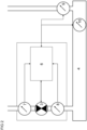
- FIG 1 shows a refrigerant circuit (1) not according to the invention.
- the refrigerant circuit (1) can, by way of non-limiting example, be a refrigerant circuit of an air-conditioning installation or system.
- the refrigerant circuit (1) can, by way of another non-limiting example, also be a refrigerant circuit of a HVAC installation or system.
- the controller (6) also is in operative communication with sensors (7, 8) arranged at the inlet and at the outlet of the at least one expansion valve (3).
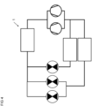
- FIG 2 shows such sensors (7, 8).
- the sensors (7, 8) function to record signals indicative of the thermodynamic states of the refrigerant at the inlet and at the outlet of the at least one expansion valve (3).
- the sensors (7, 8) advantageously are sensors (7, 8) of the refrigerant circuit (1).
- the sensors (7, 8) are sensors (7, 8) of the at least one expansion valve (3).
- the model (14) of the at least one compressor (5) produces at least one output (21, 22) selected from at least one of:
- the model (14) typically also provides topology data.
- the topology data can, by way of non-limiting examples, comprise information about numbers of layers of the neural network, about numbers of neurons in each layer, about connections between those layers, about biased neurons, etc.
- the first sensor (7) comprises a temperature sensor. It is also envisaged that the first sensor (7) comprises a pressure sensor.
- the first signal indicative of the thermodynamic state advantageously comprises a pressure signal of the refrigerant and/or a temperature signal of the refrigerant.
- the second sensor (9) comprises a temperature sensor. It is also envisaged that the second sensor (9) comprises a pressure sensor.
- the second signal indicative of the thermodynamic state advantageously comprises a pressure signal of the refrigerant and/or a temperature signal of the refrigerant.
- the pressure p a is advantageously recorded using the first sensor (7).
- ⁇ denotes a discharge coefficient of liquids.
- the discharge coefficient of liquids ⁇ is defined in a standard EN 60534-2-1. The same standard was published by CENELEC on 1 May 2011.
- the pressure p b is advantageously recorded using the third sensor (8) and/or using the second sensor (9).
- F L denotes a liquid pressure recovery factor.
- F L depends on the geometry of the valve such as the geometry of the at least one expansion valve (3).
- p c denotes a pressure at the thermodynamic critical point and p s denotes a pressure at saturation of an inlet temperature T a .
- An inlet temperature T a can ideally be recorded using the first sensor (7).
- the mass flow through the expansion valve ⁇ valve determines the current capacity of the at least one compressor Q ⁇ valve :
- Q ⁇ valve m ⁇ valve ⁇ h 1 ⁇ h 8 .
- the instant disclosure still further teaches any of the aforementioned methods involving a fourth signal, the method comprising the step of: calculating and/or determining a first value of maximum available cooling power of the refrigerant circuit (1) as a function of the first, second, and fourth signals.
- a signal indicative of a current compressor capacity of the at least one compressor (5) comprises a signal indicative of an instantaneous compressor capacity of the at least one compressor (5). It is envisaged that a signal indicative of a current compressor capacity of the at least one compressor (5) is a signal indicative of an instantaneous compressor capacity of the at least one compressor (5).
- the instant disclosure yet further teaches any of the aforementioned methods, the method comprising the step of: calculating a first value of current capacity of the refrigerant circuit (1) as a function of the third signal.
- the first value of current capacity of the refrigerant circuit (1) is a first value of current and/or instantaneous power of the refrigerant circuit (1).
- the instant disclosure also teaches any of the aforementioned methods, the method comprising the step of: calculating and/or determining a first value of current power of the refrigerant circuit (1) as a function of the third signal.
- the present invention also teaches any of the aforementioned methods, the method comprising the step of: if the determined first ratio exceeds one augmented by the first threshold: producing the first alarm signal indicative of the loss of the refrigerant.
- the first threshold is less than 0.5. That is, if the determined first ratio exceeds 1.5, the first alarm signal indicative of the loss of the refrigerant will be produced. In a special embodiment, the first threshold is less than 0.2. That is, if the determined first ratio exceeds 1.2, the first alarm signal indicative of the loss of the refrigerant will be produced. In yet another special embodiment, the first threshold is less than 0.1. That is, if the determined first ratio exceeds 1.1, the first alarm signal indicative of the loss of the refrigerant will be produced. Low first thresholds reduce likelihoods of false negatives.
- the present disclosure also teaches any of the aforementioned methods, the method comprising the step of: calculating and/or determining the first ratio by dividing the first value of current capacity by the first value of maximum available capacity.
- the present disclosure still further teaches any of the aforementioned methods, the method comprising the step of: calculating and/or determining the first ratio by dividing the first value of current power by the first value of maximum available power.
- the method of detecting a loss of a refrigerant from a refrigerant circuit (1) is a method of mitigating loss of a refrigerant from a refrigerant circuit (1). It is yet further envisaged that the method of detecting a loss of a refrigerant from a refrigerant circuit (1) is a method of mitigating loss of refrigerant from a refrigerant circuit (1).
- the present invention also teaches any of the aforementioned methods, wherein the refrigerant circuit (1) comprises a condenser (2).
- the condenser (2) advantageously is in fluid communication with the at least one expansion valve (3).
- the condenser (2) advantageously is in fluid communication with the at least one compressor (5), too.
- the instant disclosure still teaches any of the aforementioned methods, wherein the at least one expansion valve (3) has a characteristic curve, the method comprising the step of: using the characteristic curve of the at least one expansion valve (3) to determine the first value of maximum available capacity as a function of the first and second signals.
- the instant disclosure also teaches any of the aforementioned methods involving a fourth signal, wherein the at least one expansion valve (3) has a characteristic curve, the method comprising the step of: using the characteristic curve of the at least one expansion valve (3) to calculate the first value of maximum available capacity as a function of the first, second, and fourth signals.
- the instant disclosure still further teaches any of the aforementioned methods involving a fourth signal, wherein the at least one expansion valve (3) has a characteristic curve, the method comprising the step of: using the characteristic curve of the at least one expansion valve (3) to calculate and/or to determine a first value of maximum available power as a function of the first, second, and fourth signals.
- the present disclosure also teaches any of the aforementioned methods, wherein the refrigerant circuit (1) comprises a fourth sensor associated with the at least one compressor (5), the method comprising the step of: recording the signal indicative of a current compressor capacity of the at least one compressor (5) from the fourth sensor associated with the at least one compressor (5).
- the refrigerant circuit (1) comprises a fourth sensor associated with the at least one compressor (5), the method comprising the step of:
- the fourth sensor connects to the at least one compressor (5). More specifically, the fourth sensor can electrically connect to the at least one compressor (5).
- the at least one compressor (5) comprises the fourth sensor. It is envisaged that the at least one compressor (5) comprises a housing such as a metallic housing and that the fourth sensor is secured relative to the housing of the at least one compressor (5). It is also envisaged that the at least one compressor (5) comprises a housing such as a metallic housing and that the fourth sensor is mounted to the housing of the at least one compressor (5).
- the fourth sensor is advantageously different from the first sensor (7).
- the fourth sensor is ideally different from the third sensor (8).
- the fourth sensor is advantageously different from the second sensor (9).
- the fourth sensor is ideally different from the fifth sensor.
- the fourth sensor is preferably different from the sixth sensor (10).
- the present disclosure further teaches any of the aforementioned methods, the method comprising the step of: recording the signal indicative of a current compressor capacity of the at least one compressor (5) from a speed signal associated with the at least one compressor (5).
- the refrigerant circuit (1) comprises a pulse-width modulation circuit. It is envisaged that the refrigerant circuit (1) comprises a housing such as a metallic housing and that the pulse-width modulation circuit is secured relative to the housing of the refrigerant circuit (1). It is also envisaged that the refrigerant circuit (1) comprises a housing such as a metallic housing and that the pulse-width modulation circuit is mounted to the housing of the refrigerant circuit (1).
- the pulse-width modulation circuit advantageously connects to the at least one compressor (5).
- the present disclosure also teaches any of the aforementioned methods, wherein the refrigerant circuit (1) comprises a fifth sensor associated with the at least one compressor (5), the method comprising the step of: recording the signal indicative of a current compressor capacity of the at least one compressor (5) from the fifth sensor associated with the at least one compressor (5).
- the present invention also teaches any of the aforementioned methods, wherein the refrigerant circuit (1) comprises a sixth sensor (10) associated with the at least one evaporator (4), the method comprising the step of: recording the signal indicative of power currently dissipated by the at least one evaporator (4) using the sixth sensor (10).
- the at least one expansion valve (3) comprises a valve member, the valve member being movable between an open position which allows refrigerant flow through the at least one expansion valve (3) and a closed position which obturates refrigerant flow through the at least one expansion valve (3), the method comprising the steps of:
- the at least one expansion valve (3) comprises a valve member, the valve member being movable between an open position which allows refrigerant flow through the at least one expansion valve (3) and a closed position which obturates refrigerant flow through the at least one expansion valve (3), the method comprising the steps of:
- the instant disclosure still further teaches any of the aforementioned methods involving a position signal and a characteristic curve of at least one expansion valve (3), the method comprising the steps of:
- the visible indicator (11 - 13) advantageously comprises a light-emitting diode and/or a display.
- the visible indicator (11 - 13) comprises a diode emitting red light.
- the visible indicator (11 - 13) is a diode emitting red light.
- the instant disclosure also teaches any of the aforementioned methods involving a sixth signal, the method comprising the step of: calculating the third ratio by relating the third value of current capacity to the second value of maximum available capacity.
- the instant disclosure yet further teaches any of the aforementioned methods involving a sixth signal, the method comprising the step of: calculating the difference between the third ratio and the first ratio.
- the third threshold is a third predetermined threshold.
- evaporator (4) comprises an inlet port and wherein the refrigerant circuit (1) comprises a conduit connecting the outlet port of the at least one expansion valve (3) to the inlet port of the at least one evaporator (4), wherein a flow of refrigerant through the conduit causes a decrease in pressure of the refrigerant, the method comprising the step of: determining the first value of maximum available capacity of the refrigerant circuit (1) as a function of the first and second signals and as a function of the decrease in pressure of the refrigerant.
- the present disclosure also teaches any of the aforementioned methods involving a fourth signal and a decrease in pressure of the refrigerant, the method comprising the step of: calculating the first value of maximum available capacity of the refrigerant circuit (1) as a function of the first, second, and fourth signals and as a function of the decrease in pressure of the refrigerant.
- the present disclosure still teaches any of the aforementioned methods involving a sixth signal and involving a decrease in pressure of the refrigerant, the method comprising the step of: calculating and/or determining the second value of maximum available capacity of the refrigerant circuit (1) as a function of the sixth and seventh signals and as a function of the decrease in pressure of the refrigerant.
Landscapes
- Engineering & Computer Science (AREA)
- Physics & Mathematics (AREA)
- Mechanical Engineering (AREA)
- Thermal Sciences (AREA)
- General Engineering & Computer Science (AREA)
- Air Conditioning Control Device (AREA)
Claims (14)
- Procédé de détection d'une perte d'un réfrigérant à partir d'un circuit de réfrigérant (1) comprenant au moins un condenseur (2), au moins un compresseur (5), et au moins un évaporateur (4) ayant un orifice de sortie, et au moins un détendeur (3) ayant un orifice d'entrée et un orifice de sortie, le circuit de réfrigérant (1) comprenant également un premier capteur (7) pour l'enregistrement d'un état thermodynamique du réfrigérant au niveau de l'orifice d'entrée de l'au moins un détendeur (3) et/ou d'un état thermodynamique du réfrigérant au niveau ou près de l'au moins un condenseur (2), et un deuxième capteur (9) pour l'enregistrement d'un état thermodynamique du réfrigérant au niveau de l'orifice de sortie de l'au moins un évaporateur (4), le procédé comprenant les étapes de :l'enregistrement d'un premier signal indicatif d'un état thermodynamique du réfrigérant à l'aide du premier capteur (7) ;l'enregistrement d'un deuxième signal indicatif d'un état thermodynamique du réfrigérant à l'aide du deuxième capteur (9) ;caractérisé en ce que le procédé comprend les étapes dela détermination d'une première valeur de capacité disponible maximale du circuit de réfrigérant (1) en fonction des premier et deuxième signaux ;l'enregistrement d'un troisième signal, le troisième signal étant- un signal indicatif d'une puissance actuellement dissipée par l'au moins un évaporateur (4) ;la détermination d'une première valeur de capacité actuelle du circuit de réfrigérant (1) en fonction du troisième signal ;la détermination d'un premier rapport par la mise en relation de la première valeur de capacité actuelle avec la première valeur de capacité disponible maximale ; etsi le premier rapport déterminé dépasse un d'un premier seuil :la production d'un premier signal d'alarme indicatif de la perte du réfrigérant ;caractérisé en outre en ce quele circuit de réfrigérant (1) comprend un autre capteur (10) associé à l'au moins un évaporateur (4) ;le procédé comprenant en outre l'étape de :
l'enregistrement du signal indicatif d'une puissance actuellement dissipée par l'au moins un évaporateur (4) à l'aide de l'autre capteur (10). - Le procédé selon la revendication 1, dans lequel l'au moins un détendeur (3) possède une courbe caractéristique, le procédé comprenant l'étape de :
l'utilisation de la courbe caractéristique de l'au moins un détendeur (3) pour déterminer la première valeur de capacité disponible maximale en fonction des premier et deuxième signaux. - Le procédé selon l'une quelconque des revendications 1 à 2, le procédé comprenant les étapes de :la réception d'un signal de demande, le signal de demande comprenant une requête, adressée à l'au moins un compresseur (5), pour qu'il fonctionne à une capacité de compresseur indiquée ; etla production du signal indicatif de la capacité de compresseur actuelle de l'au moins un compresseur (5) en fonction du signal de demande.
- Le procédé selon l'une quelconque des revendications 1 à 3, dans lequel le circuit de réfrigérant (1) comprend un quatrième capteur associé à l'au moins un compresseur (5), le quatrième capteur comprenant un capteur de vitesse, le procédé comprenant l'étape de :
l'enregistrement du signal indicatif d'une capacité de compresseur actuelle de l'au moins un compresseur (5) à partir du quatrième capteur associé à l'au moins un compresseur (5). - Le procédé selon l'une quelconque des revendications 1 à 3, le procédé comprenant l'étape de :
l'enregistrement du signal indicatif d'une capacité de compresseur actuelle de l'au moins un compresseur (5) à partir d'un signal de vitesse émis vers l'au moins un compresseur (5). - Le procédé selon l'une quelconque des revendications 1 à 5, dans lequel le circuit de réfrigérant (1) comprend un cinquième capteur associé à l'au moins un compresseur (5), le cinquième capteur comprenant un capteur de débit massique, le procédé comprenant l'étape de :
l'enregistrement du signal indicatif d'une capacité de compresseur actuelle de l'au moins un compresseur (5) à partir du cinquième capteur associé à l'au moins un compresseur (5). - Le procédé selon l'une quelconque des revendications 1 à 6, dans lequel l'au moins un détendeur (3) comprend un organe soupape, l'organe soupape étant mobile entre une position ouverte qui permet un écoulement de réfrigérant à travers l'au moins un détendeur (3) et une position fermée qui obture l'écoulement de réfrigérant à travers l'au moins un détendeur (3), le procédé comprenant les étapes de :l'enregistrement, à partir de l'au moins un détendeur (3), d'un signal de position indicatif de la position de l'organe soupape ; etla détermination de la première valeur de capacité disponible maximale du circuit de réfrigérant (1) en fonction des premier et deuxième signaux et en fonction du signal de position.
- Le procédé selon les revendications 2 et 7, le procédé comprenant les étapes de :l'enregistrement, à partir de l'au moins un détendeur (3), du signal de position indicatif de la position de l'organe soupape ; etl'utilisation de la courbe caractéristique de l'au moins un détendeur (3) pour déterminer la première valeur de capacité disponible maximale du circuit de réfrigérant (1) en fonction des premier et deuxième signaux et en fonction du signal de position.
- Le procédé selon l'une quelconque des revendications 1 à 8, dans lequel le circuit de réfrigérant (1) comprend un indicateur visible (11 à 13), le procédé comprenant l'étape de :
si le premier rapport déterminé dépasse un du premier seuil :
l'activation de l'indicateur visible (11 à 13). - Le procédé selon l'une quelconque des revendications 1 à 9, le procédé comprenant les étapes de :après l'enregistrement du troisième signal, l'enregistrement d'un cinquième signal, le cinquième signal étant sélectionné parmi au moins l'un- d'un signal indicatif d'une capacité de compresseur actuelle de l'au moins un compresseur (5) ;- d'un signal indicatif d'une puissance actuellement dissipée par l'au moins un évaporateur (4) ;la détermination d'une deuxième valeur de capacité actuelle du circuit de réfrigérant (1) en fonction du cinquième signal ;la détermination d'un deuxième rapport par la mise en relation de la deuxième valeur de capacité actuelle avec la première valeur de capacité disponible maximale ;la détermination d'une différence entre le deuxième rapport et le premier rapport ; etsi la différence entre le deuxième rapport et le premier rapport dépasse un deuxième seuil :
la production d'un deuxième signal d'alarme indicatif de la perte du réfrigérant. - Le procédé selon l'une quelconque des revendications 1 à 10, le procédé comprenant les étapes de :après l'enregistrement du premier signal, l'enregistrement d'un sixième signal indicatif d'un état thermodynamique du réfrigérant à l'aide du premier capteur (7) ;après l'enregistrement du deuxième signal, l'enregistrement d'un septième signal indicatif d'un état thermodynamique du réfrigérant à l'aide du deuxième capteur (9) ;la détermination d'une deuxième valeur de capacité disponible maximale du circuit de réfrigérant (1) en fonction des sixième et septième signaux ;après l'enregistrement du troisième signal, l'enregistrement d'un huitième signal, le huitième signal étant sélectionné parmi au moins l'un- d'un signal indicatif d'une capacité de compresseur actuelle de l'au moins un compresseur (5) ;- d'un signal indicatif d'une puissance actuellement dissipée par l'au moins un évaporateur (4) ;la détermination d'une troisième valeur de capacité actuelle du circuit de réfrigérant (1) en fonction du huitième signal ;la détermination d'un troisième rapport par la mise en relation de la troisième valeur de capacité actuelle avec la deuxième valeur de capacité disponible maximale ;la détermination d'une différence entre le troisième rapport et le premier rapport ; etsi la différence entre le troisième rapport et le premier rapport dépasse un troisième seuil :
la production d'un troisième signal d'alarme indicatif de la perte du réfrigérant. - Le procédé selon l'une quelconque des revendications 1 à 11, dans lequel l'évaporateur (4) comprend un orifice d'entrée et dans lequel le circuit de réfrigérant (1) comprend un conduit raccordant l'orifice de sortie de l'au moins un détendeur (3) à l'orifice d'entrée de l'au moins un évaporateur (4), dans lequel un écoulement de réfrigérant à travers le conduit provoque une diminution de pression du réfrigérant, le procédé comprenant l'étape de :
la détermination de la première valeur de capacité disponible maximale du circuit de réfrigérant (1) en fonction des premier et deuxième signaux et en fonction de la diminution de pression du réfrigérant. - Programme d'ordinateur comprenant des instructions qui, lorsque le programme est exécuté par un ordinateur, amènent l'ordinateur à effectuer les étapes de l'un quelconque des procédés selon les revendications 1 à 12.
- Support lisible par ordinateur ayant, stocké sur celui-ci, le programme d'ordinateur selon la revendication 13.
Priority Applications (2)
| Application Number | Priority Date | Filing Date | Title |
|---|---|---|---|
| EP20209861.2A EP4006454B1 (fr) | 2020-11-25 | 2020-11-25 | Procédé de détection d'une perte de réfrigérant |
| DK20209861.2T DK4006454T3 (da) | 2020-11-25 | 2020-11-25 | Fremgangsmåde til detektering af et tab af et kølemiddel |
Applications Claiming Priority (1)
| Application Number | Priority Date | Filing Date | Title |
|---|---|---|---|
| EP20209861.2A EP4006454B1 (fr) | 2020-11-25 | 2020-11-25 | Procédé de détection d'une perte de réfrigérant |
Publications (2)
| Publication Number | Publication Date |
|---|---|
| EP4006454A1 EP4006454A1 (fr) | 2022-06-01 |
| EP4006454B1 true EP4006454B1 (fr) | 2023-03-15 |
Family
ID=73597978
Family Applications (1)
| Application Number | Title | Priority Date | Filing Date |
|---|---|---|---|
| EP20209861.2A Active EP4006454B1 (fr) | 2020-11-25 | 2020-11-25 | Procédé de détection d'une perte de réfrigérant |
Country Status (2)
| Country | Link |
|---|---|
| EP (1) | EP4006454B1 (fr) |
| DK (1) | DK4006454T3 (fr) |
Cited By (1)
| Publication number | Priority date | Publication date | Assignee | Title |
|---|---|---|---|---|
| EP4664038A1 (fr) | 2024-06-14 | 2025-12-17 | Siemens Schweiz AG | Détection de défaut d'un détendeur |
Family Cites Families (5)
| Publication number | Priority date | Publication date | Assignee | Title |
|---|---|---|---|---|
| DE102004019929B4 (de) | 2004-04-21 | 2006-07-20 | Siemens Ag | Klimaanlage mit einer Vorrichtung zum Erfassen einer Gasleckage |
| US7380404B2 (en) * | 2005-01-05 | 2008-06-03 | Carrier Corporation | Method and control for determining low refrigerant charge |
| US20110112814A1 (en) | 2009-11-11 | 2011-05-12 | Emerson Retail Services, Inc. | Refrigerant leak detection system and method |
| JP5147889B2 (ja) * | 2010-04-12 | 2013-02-20 | 三菱電機株式会社 | 空気調和装置 |
| FR3091336B1 (fr) * | 2018-12-31 | 2021-01-29 | Faiveley Transp Tours | Méthode de détermination du niveau de charge en fluide réfrigérant dans un circuit de refroidissement pour un système de climatisation |
-
2020
- 2020-11-25 EP EP20209861.2A patent/EP4006454B1/fr active Active
- 2020-11-25 DK DK20209861.2T patent/DK4006454T3/da active
Cited By (1)
| Publication number | Priority date | Publication date | Assignee | Title |
|---|---|---|---|---|
| EP4664038A1 (fr) | 2024-06-14 | 2025-12-17 | Siemens Schweiz AG | Détection de défaut d'un détendeur |
Also Published As
| Publication number | Publication date |
|---|---|
| EP4006454A1 (fr) | 2022-06-01 |
| DK4006454T3 (da) | 2023-05-30 |
Similar Documents
| Publication | Publication Date | Title |
|---|---|---|
| CN114585528B (zh) | 用于休闲旅游车的空调设备 | |
| EP2812640B1 (fr) | Procédé de détection de perte de fluide frigorifique | |
| JP4071486B2 (ja) | 冷媒充填量を監視する方法 | |
| EP1731857B1 (fr) | Dispositif de diagnostic de dispositif | |
| JP5787604B2 (ja) | 車両用空気調和装置故障診断システム及び故障診断装置 | |
| US5301514A (en) | Low refrigerant charge detection by monitoring thermal expansion valve oscillation | |
| US5586445A (en) | Low refrigerant charge detection using a combined pressure/temperature sensor | |
| US7188482B2 (en) | Fault diagnostics and prognostics based on distance fault classifiers | |
| CN110895020B (zh) | 一种制冷剂泄漏检测方法及空调器 | |
| US6681582B2 (en) | Vapor compression type refrigeration apparatus including leak detection and method for detecting refrigerant leaks | |
| EP3545241B1 (fr) | Procédé de gestion de l'atténuation des défaillances de compresseur dans un système de compression de vapeur | |
| EP1706684B1 (fr) | Procede pour diagnostiquer une perte de charge refrigerante dans un systeme refrigerant | |
| CN101578491B (zh) | 制冷运输系统 | |
| CN104964496A (zh) | 用于监测压缩机过热的系统和方法 | |
| US20060144059A1 (en) | Method and control for determining low refrigerant charge | |
| EP2426433A2 (fr) | Dispositif d'évaluation de la performance pour dispositif frigorifique centrifuge | |
| US10533783B2 (en) | Air conditioner having compressor bypass and evaluation of volume of connecting pipe | |
| US20170003679A1 (en) | Chiller control device, chiller, and chiller diagnostic method | |
| Li et al. | Virtual refrigerant pressure sensors for use in monitoring and fault diagnosis of vapor-compression equipment | |
| CN110836519A (zh) | 一种空调器冷媒泄漏检测方法及检测系统 | |
| US6101820A (en) | Method and device for diagnosing an air-conditioning loop of a motor vehicle | |
| CN106524419A (zh) | 空调控制方法及空调设备 | |
| EP4006454B1 (fr) | Procédé de détection d'une perte de réfrigérant | |
| US12385679B2 (en) | Refrigerant quantity diagnosis device, refrigerant system, and refrigerant quantity diagnosis method | |
| CN100376854C (zh) | 用于计算制冷循环中的压缩机制冷剂进气压力的设备 |
Legal Events
| Date | Code | Title | Description |
|---|---|---|---|
| PUAI | Public reference made under article 153(3) epc to a published international application that has entered the european phase |
Free format text: ORIGINAL CODE: 0009012 |
|
| STAA | Information on the status of an ep patent application or granted ep patent |
Free format text: STATUS: REQUEST FOR EXAMINATION WAS MADE |
|
| 17P | Request for examination filed |
Effective date: 20210604 |
|
| AK | Designated contracting states |
Kind code of ref document: A1 Designated state(s): AL AT BE BG CH CY CZ DE DK EE ES FI FR GB GR HR HU IE IS IT LI LT LU LV MC MK MT NL NO PL PT RO RS SE SI SK SM TR |
|
| GRAP | Despatch of communication of intention to grant a patent |
Free format text: ORIGINAL CODE: EPIDOSNIGR1 |
|
| STAA | Information on the status of an ep patent application or granted ep patent |
Free format text: STATUS: GRANT OF PATENT IS INTENDED |
|
| RIC1 | Information provided on ipc code assigned before grant |
Ipc: F25B 49/00 20060101AFI20220909BHEP |
|
| INTG | Intention to grant announced |
Effective date: 20221011 |
|
| GRAS | Grant fee paid |
Free format text: ORIGINAL CODE: EPIDOSNIGR3 |
|
| GRAA | (expected) grant |
Free format text: ORIGINAL CODE: 0009210 |
|
| STAA | Information on the status of an ep patent application or granted ep patent |
Free format text: STATUS: THE PATENT HAS BEEN GRANTED |
|
| AK | Designated contracting states |
Kind code of ref document: B1 Designated state(s): AL AT BE BG CH CY CZ DE DK EE ES FI FR GB GR HR HU IE IS IT LI LT LU LV MC MK MT NL NO PL PT RO RS SE SI SK SM TR |
|
| REG | Reference to a national code |
Ref country code: CH Ref legal event code: EP Ref country code: GB Ref legal event code: FG4D |
|
| REG | Reference to a national code |
Ref country code: DE Ref legal event code: R096 Ref document number: 602020008856 Country of ref document: DE |
|
| REG | Reference to a national code |
Ref country code: IE Ref legal event code: FG4D |
|
| REG | Reference to a national code |
Ref country code: AT Ref legal event code: REF Ref document number: 1554221 Country of ref document: AT Kind code of ref document: T Effective date: 20230415 |
|
| REG | Reference to a national code |
Ref country code: DK Ref legal event code: T3 Effective date: 20230524 |
|
| REG | Reference to a national code |
Ref country code: LT Ref legal event code: MG9D |
|
| REG | Reference to a national code |
Ref country code: NL Ref legal event code: MP Effective date: 20230315 |
|
| PG25 | Lapsed in a contracting state [announced via postgrant information from national office to epo] |
Ref country code: RS Free format text: LAPSE BECAUSE OF FAILURE TO SUBMIT A TRANSLATION OF THE DESCRIPTION OR TO PAY THE FEE WITHIN THE PRESCRIBED TIME-LIMIT Effective date: 20230315 Ref country code: NO Free format text: LAPSE BECAUSE OF FAILURE TO SUBMIT A TRANSLATION OF THE DESCRIPTION OR TO PAY THE FEE WITHIN THE PRESCRIBED TIME-LIMIT Effective date: 20230615 Ref country code: LV Free format text: LAPSE BECAUSE OF FAILURE TO SUBMIT A TRANSLATION OF THE DESCRIPTION OR TO PAY THE FEE WITHIN THE PRESCRIBED TIME-LIMIT Effective date: 20230315 Ref country code: LT Free format text: LAPSE BECAUSE OF FAILURE TO SUBMIT A TRANSLATION OF THE DESCRIPTION OR TO PAY THE FEE WITHIN THE PRESCRIBED TIME-LIMIT Effective date: 20230315 Ref country code: HR Free format text: LAPSE BECAUSE OF FAILURE TO SUBMIT A TRANSLATION OF THE DESCRIPTION OR TO PAY THE FEE WITHIN THE PRESCRIBED TIME-LIMIT Effective date: 20230315 |
|
| REG | Reference to a national code |
Ref country code: AT Ref legal event code: MK05 Ref document number: 1554221 Country of ref document: AT Kind code of ref document: T Effective date: 20230315 |
|
| PG25 | Lapsed in a contracting state [announced via postgrant information from national office to epo] |
Ref country code: SE Free format text: LAPSE BECAUSE OF FAILURE TO SUBMIT A TRANSLATION OF THE DESCRIPTION OR TO PAY THE FEE WITHIN THE PRESCRIBED TIME-LIMIT Effective date: 20230315 Ref country code: NL Free format text: LAPSE BECAUSE OF FAILURE TO SUBMIT A TRANSLATION OF THE DESCRIPTION OR TO PAY THE FEE WITHIN THE PRESCRIBED TIME-LIMIT Effective date: 20230315 Ref country code: GR Free format text: LAPSE BECAUSE OF FAILURE TO SUBMIT A TRANSLATION OF THE DESCRIPTION OR TO PAY THE FEE WITHIN THE PRESCRIBED TIME-LIMIT Effective date: 20230616 Ref country code: FI Free format text: LAPSE BECAUSE OF FAILURE TO SUBMIT A TRANSLATION OF THE DESCRIPTION OR TO PAY THE FEE WITHIN THE PRESCRIBED TIME-LIMIT Effective date: 20230315 |
|
| PG25 | Lapsed in a contracting state [announced via postgrant information from national office to epo] |
Ref country code: SM Free format text: LAPSE BECAUSE OF FAILURE TO SUBMIT A TRANSLATION OF THE DESCRIPTION OR TO PAY THE FEE WITHIN THE PRESCRIBED TIME-LIMIT Effective date: 20230315 Ref country code: RO Free format text: LAPSE BECAUSE OF FAILURE TO SUBMIT A TRANSLATION OF THE DESCRIPTION OR TO PAY THE FEE WITHIN THE PRESCRIBED TIME-LIMIT Effective date: 20230315 Ref country code: PT Free format text: LAPSE BECAUSE OF FAILURE TO SUBMIT A TRANSLATION OF THE DESCRIPTION OR TO PAY THE FEE WITHIN THE PRESCRIBED TIME-LIMIT Effective date: 20230717 Ref country code: ES Free format text: LAPSE BECAUSE OF FAILURE TO SUBMIT A TRANSLATION OF THE DESCRIPTION OR TO PAY THE FEE WITHIN THE PRESCRIBED TIME-LIMIT Effective date: 20230315 Ref country code: EE Free format text: LAPSE BECAUSE OF FAILURE TO SUBMIT A TRANSLATION OF THE DESCRIPTION OR TO PAY THE FEE WITHIN THE PRESCRIBED TIME-LIMIT Effective date: 20230315 Ref country code: AT Free format text: LAPSE BECAUSE OF FAILURE TO SUBMIT A TRANSLATION OF THE DESCRIPTION OR TO PAY THE FEE WITHIN THE PRESCRIBED TIME-LIMIT Effective date: 20230315 |
|
| PG25 | Lapsed in a contracting state [announced via postgrant information from national office to epo] |
Ref country code: SK Free format text: LAPSE BECAUSE OF FAILURE TO SUBMIT A TRANSLATION OF THE DESCRIPTION OR TO PAY THE FEE WITHIN THE PRESCRIBED TIME-LIMIT Effective date: 20230315 Ref country code: PL Free format text: LAPSE BECAUSE OF FAILURE TO SUBMIT A TRANSLATION OF THE DESCRIPTION OR TO PAY THE FEE WITHIN THE PRESCRIBED TIME-LIMIT Effective date: 20230315 Ref country code: IS Free format text: LAPSE BECAUSE OF FAILURE TO SUBMIT A TRANSLATION OF THE DESCRIPTION OR TO PAY THE FEE WITHIN THE PRESCRIBED TIME-LIMIT Effective date: 20230715 |
|
| REG | Reference to a national code |
Ref country code: DE Ref legal event code: R097 Ref document number: 602020008856 Country of ref document: DE |
|
| PLBE | No opposition filed within time limit |
Free format text: ORIGINAL CODE: 0009261 |
|
| STAA | Information on the status of an ep patent application or granted ep patent |
Free format text: STATUS: NO OPPOSITION FILED WITHIN TIME LIMIT |
|
| PG25 | Lapsed in a contracting state [announced via postgrant information from national office to epo] |
Ref country code: SI Free format text: LAPSE BECAUSE OF FAILURE TO SUBMIT A TRANSLATION OF THE DESCRIPTION OR TO PAY THE FEE WITHIN THE PRESCRIBED TIME-LIMIT Effective date: 20230315 |
|
| 26N | No opposition filed |
Effective date: 20231218 |
|
| PG25 | Lapsed in a contracting state [announced via postgrant information from national office to epo] |
Ref country code: MC Free format text: LAPSE BECAUSE OF FAILURE TO SUBMIT A TRANSLATION OF THE DESCRIPTION OR TO PAY THE FEE WITHIN THE PRESCRIBED TIME-LIMIT Effective date: 20230315 |
|
| PG25 | Lapsed in a contracting state [announced via postgrant information from national office to epo] |
Ref country code: LU Free format text: LAPSE BECAUSE OF NON-PAYMENT OF DUE FEES Effective date: 20231125 |
|
| PG25 | Lapsed in a contracting state [announced via postgrant information from national office to epo] |
Ref country code: MC Free format text: LAPSE BECAUSE OF FAILURE TO SUBMIT A TRANSLATION OF THE DESCRIPTION OR TO PAY THE FEE WITHIN THE PRESCRIBED TIME-LIMIT Effective date: 20230315 Ref country code: LU Free format text: LAPSE BECAUSE OF NON-PAYMENT OF DUE FEES Effective date: 20231125 |
|
| REG | Reference to a national code |
Ref country code: BE Ref legal event code: MM Effective date: 20231130 |
|
| REG | Reference to a national code |
Ref country code: IE Ref legal event code: MM4A |
|
| PG25 | Lapsed in a contracting state [announced via postgrant information from national office to epo] |
Ref country code: IE Free format text: LAPSE BECAUSE OF NON-PAYMENT OF DUE FEES Effective date: 20231125 |
|
| PG25 | Lapsed in a contracting state [announced via postgrant information from national office to epo] |
Ref country code: BE Free format text: LAPSE BECAUSE OF NON-PAYMENT OF DUE FEES Effective date: 20231130 |
|
| PG25 | Lapsed in a contracting state [announced via postgrant information from national office to epo] |
Ref country code: IE Free format text: LAPSE BECAUSE OF NON-PAYMENT OF DUE FEES Effective date: 20231125 Ref country code: BE Free format text: LAPSE BECAUSE OF NON-PAYMENT OF DUE FEES Effective date: 20231130 |
|
| PG25 | Lapsed in a contracting state [announced via postgrant information from national office to epo] |
Ref country code: BG Free format text: LAPSE BECAUSE OF FAILURE TO SUBMIT A TRANSLATION OF THE DESCRIPTION OR TO PAY THE FEE WITHIN THE PRESCRIBED TIME-LIMIT Effective date: 20230315 |
|
| PG25 | Lapsed in a contracting state [announced via postgrant information from national office to epo] |
Ref country code: BG Free format text: LAPSE BECAUSE OF FAILURE TO SUBMIT A TRANSLATION OF THE DESCRIPTION OR TO PAY THE FEE WITHIN THE PRESCRIBED TIME-LIMIT Effective date: 20230315 |
|
| GBPC | Gb: european patent ceased through non-payment of renewal fee |
Effective date: 20241125 |
|
| PG25 | Lapsed in a contracting state [announced via postgrant information from national office to epo] |
Ref country code: CY Free format text: LAPSE BECAUSE OF FAILURE TO SUBMIT A TRANSLATION OF THE DESCRIPTION OR TO PAY THE FEE WITHIN THE PRESCRIBED TIME-LIMIT; INVALID AB INITIO Effective date: 20201125 |
|
| PG25 | Lapsed in a contracting state [announced via postgrant information from national office to epo] |
Ref country code: HU Free format text: LAPSE BECAUSE OF FAILURE TO SUBMIT A TRANSLATION OF THE DESCRIPTION OR TO PAY THE FEE WITHIN THE PRESCRIBED TIME-LIMIT; INVALID AB INITIO Effective date: 20201125 |
|
| PG25 | Lapsed in a contracting state [announced via postgrant information from national office to epo] |
Ref country code: GB Free format text: LAPSE BECAUSE OF NON-PAYMENT OF DUE FEES Effective date: 20241125 |
|
| PG25 | Lapsed in a contracting state [announced via postgrant information from national office to epo] |
Ref country code: TR Free format text: LAPSE BECAUSE OF FAILURE TO SUBMIT A TRANSLATION OF THE DESCRIPTION OR TO PAY THE FEE WITHIN THE PRESCRIBED TIME-LIMIT Effective date: 20230315 |
|
| PGFP | Annual fee paid to national office [announced via postgrant information from national office to epo] |
Ref country code: DK Payment date: 20251125 Year of fee payment: 6 Ref country code: IT Payment date: 20251125 Year of fee payment: 6 |
|
| PGFP | Annual fee paid to national office [announced via postgrant information from national office to epo] |
Ref country code: FR Payment date: 20251114 Year of fee payment: 6 |
|
| PGFP | Annual fee paid to national office [announced via postgrant information from national office to epo] |
Ref country code: CZ Payment date: 20251119 Year of fee payment: 6 |
|
| REG | Reference to a national code |
Ref country code: CH Ref legal event code: U11 Free format text: ST27 STATUS EVENT CODE: U-0-0-U10-U11 (AS PROVIDED BY THE NATIONAL OFFICE) Effective date: 20260209 |
|
| PGFP | Annual fee paid to national office [announced via postgrant information from national office to epo] |
Ref country code: DE Payment date: 20260119 Year of fee payment: 6 |
|
| PGFP | Annual fee paid to national office [announced via postgrant information from national office to epo] |
Ref country code: CH Payment date: 20260209 Year of fee payment: 6 |