EP4006463B1 - Hilfsgriff und kühlschrank damit - Google Patents
Hilfsgriff und kühlschrank damit Download PDFInfo
- Publication number
- EP4006463B1 EP4006463B1 EP19939510.4A EP19939510A EP4006463B1 EP 4006463 B1 EP4006463 B1 EP 4006463B1 EP 19939510 A EP19939510 A EP 19939510A EP 4006463 B1 EP4006463 B1 EP 4006463B1
- Authority
- EP
- European Patent Office
- Prior art keywords
- handle
- tooth
- push rod
- door body
- rod
- Prior art date
- Legal status (The legal status is an assumption and is not a legal conclusion. Google has not performed a legal analysis and makes no representation as to the accuracy of the status listed.)
- Active
Links
Images
Classifications
-
- E—FIXED CONSTRUCTIONS
- E05—LOCKS; KEYS; WINDOW OR DOOR FITTINGS; SAFES
- E05B—LOCKS; ACCESSORIES THEREFOR; HANDCUFFS
- E05B1/00—Knobs or handles for wings; Knobs, handles, or press buttons for locks or latches on wings
- E05B1/0015—Knobs or handles which do not operate the bolt or lock, e.g. non-movable; Mounting thereof
-
- E—FIXED CONSTRUCTIONS
- E05—LOCKS; KEYS; WINDOW OR DOOR FITTINGS; SAFES
- E05B—LOCKS; ACCESSORIES THEREFOR; HANDCUFFS
- E05B1/00—Knobs or handles for wings; Knobs, handles, or press buttons for locks or latches on wings
- E05B1/0061—Knobs or handles with protective cover, buffer or shock absorber
-
- E—FIXED CONSTRUCTIONS
- E05—LOCKS; KEYS; WINDOW OR DOOR FITTINGS; SAFES
- E05B—LOCKS; ACCESSORIES THEREFOR; HANDCUFFS
- E05B17/00—Accessories in connection with locks
- E05B17/0025—Devices for forcing the wing firmly against its seat or to initiate the opening of the wing
- E05B17/0033—Devices for forcing the wing firmly against its seat or to initiate the opening of the wing for opening only
-
- E—FIXED CONSTRUCTIONS
- E05—LOCKS; KEYS; WINDOW OR DOOR FITTINGS; SAFES
- E05B—LOCKS; ACCESSORIES THEREFOR; HANDCUFFS
- E05B65/00—Locks or fastenings for special use
- E05B65/0042—For refrigerators or cold rooms
-
- F—MECHANICAL ENGINEERING; LIGHTING; HEATING; WEAPONS; BLASTING
- F25—REFRIGERATION OR COOLING; COMBINED HEATING AND REFRIGERATION SYSTEMS; HEAT PUMP SYSTEMS; MANUFACTURE OR STORAGE OF ICE; LIQUEFACTION SOLIDIFICATION OF GASES
- F25D—REFRIGERATORS; COLD ROOMS; ICE-BOXES; COOLING OR FREEZING APPARATUS NOT OTHERWISE PROVIDED FOR
- F25D23/00—General constructional features
- F25D23/02—Doors; Covers
- F25D23/028—Details
Definitions
- the present invention relates to the technical field of household refrigeration electrical appliance, and specifically to a handle for a refrigerator and a refrigerator having the handle.
- the refrigerator is such an apparatus that it stores various food in a refrigerated state or a frozen state for a period of time in a preserved manner.
- an assist handle disposed on the door body of the refrigerator is developed, enables the door body of the refrigerator to be opened with less force, and improves the user's comfort in use.
- the assist handles used have the following defects: 1) the assists handle is mounted on a side surface of a lateral edge of the door body, and the door body needs to be narrower than the width of the cabinet, which affects the appearance of the refrigerator; 2) the handle is mounted on the front of the door body, and the door body needs to be perforated, which causes problems such as leakage of cold and frosting.
- CN109403717B discloses a handle component and a refrigerator.
- the handle component comprises a door body, a handle, a push rod and a transmission part and the door body comprises a mounting chamber.
- the handle is fixed to one side of the mounting chamber and the handle and the door body surround together to form a hand stretching position.
- the push rod is movably accommodated inside the mounting chamber, the transmission part is hinged to the door body, the first end of the transmission part is connected with the push rod and the second end of the transmission part is stressed to drive the first end of the transmission part to rotate by taking the hinging axis of the transmission part and the door body as the center so as to drive the first end of the push rod to move.
- the second end of the transmission part is positioned inside the hand stretching position.
- the invention provides an assist handle suitable for refrigerators, which does not affect the appearance of the refrigerators, and meanwhile can provide better comfort in use.
- the present invention provides an assist handle according to claim 1.
- the present invention also relates to a refrigerator according to claim 9.
- the present invention provides the assist handle and the refrigerator, the assist handle comprises the resistance structure, and the resistance structure moves along with the push rod and generates a rotation resistance; when the user pulls the handle bar to open the door body, the rotation resistance enhances the door-opening comfort; when the handle bar returns, the rotation resistance reduces the noise caused by the return of the handle bar.
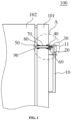
- FIG. 1 is a cross-sectional view of a refrigerator mounted with an assist handle according to the present invention
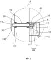
- FIG. 2 is an enlarged schematic view of a region A in FIG. 1
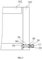
- FIG. 3 is a top view of the refrigerator mounted with an assist handle according to the present invention with a top structure being removed.
- a refrigerator 100 comprises a door body 101 and a cabinet 102.
- the door body 101 is pivoted to a lateral edge of the cabinet 102 and may pivot relative to the cabinet 102 to close the cabinet 102, or the door body may open relative to the cabinet 102.
- the cabinet 102 comprises a plurality of compartments for storing items.
- a front side of the door body 101 is provided with an assist handle.
- the assist handle comprises a handle bar, a rotation shaft 20, a guide groove 90, a push rod 50, and a resistance structure 60.
- the handle bar is pivoted to the rotation shaft 20, the guide groove 90 run through the door body 101, the push rod 50 is slidably disposed in the guide groove 90, and the resistance structure 60 is located on one side of the push rod 50; when the handle bar pivots about the rotation shaft 20 and pushes against a proximal end of the push rod 50 to make the push rod 50 to slide in the guide groove 90, a distal end of the push rod 50 pushes against the cabinet 102 to open the door body 101.
- the resistance structure 60 comprises a first tooth-like structure 61 and a second tooth-like structure 62 that mesh with each other.
- the first tooth-like structure 61 engages one side of the push rod 50 and may move along with the push rod 50, so that the first tooth-like structure 61 moves relative to the second tooth-like structure 62 to form a certain rotation resistance which is used to improve the comfort of the user pulling the handle bar to open the door and reduce the noise caused by the return of the handle bar.
- a side of the door body 101 close to the user is defined as "a front side", and the other side away from the user is defined as “a rear side”; an end of the push rod 50 close to the user is defined as a proximal end, and the end far away from the user is defined as a distal end.
- the handle bar is disposed on the front side of the door body 101 and pivoted to the rotation shaft 20 so that the handle bar can pivot about the rotation shaft 20.
- the handle bar comprises an integrally formed handle portion 10 and a lever portion 11.
- the handle portion 10 and the lever portion 11 are respectively located on both sides of the rotation shaft 20.
- a rotation shaft hole (not shown) provided on the handle bar divides the handle bar into the handle portion 10 and the lever portion 11, and the rotation engages in the rotation shaft hole, wherein a length of the handle portion 10 is greater than the length of the lever portion 11.
- a protrusion 12 is disposed at a top of the level portion 11 and abuts against the front end of the push rod 50.
- the rotation shaft 20 is for example fixed in a base 30 on the front side of the door body 101.
- the base 30 is a box with an end open. The opening of the box engages on the surface of the front side of the door body 101, and is not limited thereto.
- the rotation shaft is arranged at a connection between the handle portion and the lever portion on the handle bar, a rotation shaft hole corresponding to the rotation shaft on the handle bar is arranged in the base, and the rotation shaft on the handle bar is inserted into the rotation shaft hole so that the handle bar pivots around the rotation shaft.
- the base 30 encapsulates the lever portion 11 of the assist handle, the rotation shaft 20, a portion of the push rod 50 and an elastic member 40 therein, so that the refrigerator 100 has a good appearance.
- the push rod 50 comprises a first rod body 51 and a second rod body 52.
- the first rod body 51 and the second rod body 52 are connected by the elastic member 40.
- the elastic member 40 is for example a spring. An end of the spring is sleeved around a post on the first rod body 51, the other end of the spring is sleeved around another post on the rod body 52, and post on the first rod body 51 is opposite to the another post on the second rod body 52.
- the elastic member may also be a metal elastic sheet, the metal elastic sheet is arranged between the first rod body and the second rod body, both ends of the metal elastic sheet are respectively welded or adhered on a surface of the first rod body and another surface of the second rod body, and the surface is opposite to the another surface.
- the elastic member 40 provides an elastic force for returning the handle bar. Specifically, the user applies a force to pull the handle portion 10, so that the handle portion 10 and the lever portion 11 rotate counterclockwise about the rotation shaft 20, and the protrusion 12 of the lever portion 11 pushes against the front end of the first rod body 51, the first rod body 51 compresses the elastic member 40, the elastic member 40 acts on the front end of the second rod body 52 so that the second rod body 52 moves in the guide groove 90, and the distal end of the second rod body 52 extends out of the opening at the distal end of the guide groove 90 and pushes against the cabinet 102 to open the door body 101 relative to the cabinet 102. In the process of opening the door body 101, the elastic member 40 is compressed to be in a compressed state.
- the distal end of the second rod body 52 abuts against the cabinet 102, and the user no longer applies a force to the handle portion 10, and then the force applied to the elastic member 40 is removed.
- the elastic member 40 in the compressed state returns to an extended state to generate an elastic force, the elastic force acts on the first rod body 51, the first rod body 51 pushes the protrusion 12 of the level portion 11 to move towards the user, the lever portion 11 rotates clockwise about the rotation shaft 20, and the handle portion 10 rotates clockwise together and then returns back.
- the door body 101 is closed on the cabinet 102, the cabinet 102 pushes against the distal end of the second rod body 52, and the second rod body 52 compresses the elastic member 40 so that the portion of the second rod body 52 extending out of the guide groove 90 retracts back into the interior of the guide groove 90.
- the first rod body 51 and the elastic member 40 are located on the front side of the door body 101, and the second rod body 52 is located in the guide groove 90, but the arrangement is not limited to this. In other embodiments of the present invention, the first rod body, the elastic member and the second rod body may be simultaneously disposed in the guide groove.
- the assist handle further comprises a resistance structure 60 which is disposed on one side of the push rod 50 to provide resistance.
- the resistance structure 60 comprises a first tooth-like structure 61 and a second tooth-like structure 62 meshing with each other.
- the first tooth-like structure 61 is disposed on one side of the first rod body 51 and fixedly connected to the first rod body 51, and may move along with the first rod body 51; the second tooth-like structure 62 is located below the first tooth-like structure 61.
- the first tooth-like structure 61 is for example a rack
- the second tooth-like structure 62 is for example a gear
- the gear meshes with a distal end of the rack.
- the rotation of the lever portion 11 and the elastic force provided by the elastic piece 40 enable the first rod body 51 to move reciprocally, and then the rack moves reciprocally along with the first rod body 51.
- the gear moves clockwise or counterclockwise on the surface of the rack, and the rotation of the gear provides an appropriate rotation resistance.
- the rotation resistance reduces a movement rate of the first rod body 51 of the push rod 50 so that the second rod body 52 moves slowly along the guide groove 90 to gradually push against the cabinet 102, and the door body 101 gradually opens to improve the user's door-opening comfort;
- the rotation resistance may slow down the movement rate of the first lever body 51 so that the lever portion 11 slowly pivots to return, and the handle portion 10 does not impinge on the front side of the door body 101, thereby reducing the noise caused by the return of the handle bar.
- first tooth-like structure 61 and the second tooth-like structure 62 are disposed on the front side of the door body 101, and the first tooth-like structure 61 engages on the first rod body 51 and moves along with the first rod body 51, but the arrangement is not limited to this.
- first tooth-like structure and the second tooth-like structure may be disposed in the interior of the door body, and the first tooth-like structure engages on the second rod body.
- the guide groove 90 is provided with a guide sleeve 70 and a pair of bellows 80, wherein the guide sleeve 70 is received in the guide groove 90, and the second rod body 52 runs through the guide sleeve 70; the pair of bellows 80 are located at the openings at both ends of the guide groove 90, outer sides of the pair of bellows 80 are respectively connected to inner walls at both ends of the guide sleeve 70, and inner sides of the pair of bellows 80 are respectively sleeved on the outer surface of the proximal end and the outer surface of the distal end of the second rod body 52.
- the pair of bellows 80 may be regarded as being filled between the ends of the second rod body 52 and the ends of the guide sleeve 70 respectively so that the space between the pair of bellows 80 is a sealed space, and the sealed space may function for heat preservation and heat insulation.
- the bellows 80 near the rear side of the door body 101 is filled between the distal end of the guide sleeve 70 and the distal end of the second rod body 52, and may block the overflow of the cold air through the guide groove 90 of the door body 101 when the door body 101 closes the cabinet 102, thereby avoiding the frosting at the assist handle of the door body.
- the door body 101 comprises a first housing, a thermal insulation layer and a second housing.
- the thermal insulation layer is disposed between the first housing and the second housing.
- the guide groove 90 sequentially penetrates the first housing, the thermal insulation layer and the second housing, wherein the guide sleeve 70 is filled in the guide groove 90, a proximal end of the guide sleeve 70 is connected with the first housing, and a distal end of the guide sleeve 70 is connected with the second housing.
- the present invention further provides a refrigerator 100 comprising the door body 101 and the cabinet 102, wherein the door body 101 may be opened or closed relative to the cabinet 102, and the front side of the door body 101 is provided with the assist handle as stated above.
- the present invention provides the assist handle and the refrigerator, the assist handle comprises the resistance structure, and the resistance structure moves along with the push rod and generates a rotation resistance; when the user pulls the handle bar to open the door body, the rotation resistance enhances the door-opening comfort; when the handle bar returns, the rotation resistance reduces the noise caused by the return of the handle bar.
Landscapes
- Engineering & Computer Science (AREA)
- Physics & Mathematics (AREA)
- Thermal Sciences (AREA)
- Chemical & Material Sciences (AREA)
- Combustion & Propulsion (AREA)
- Mechanical Engineering (AREA)
- General Engineering & Computer Science (AREA)
- Refrigerator Housings (AREA)
Claims (9)
- Hilfsgriff zum Anbringen an einer Vorderseite eines Türkörpers (101) eines Kühlschranks (100), wobei der Hilfsgriffeine Griffstange, die derart konfiguriert ist, dass sie an der Vorderseite des Türkörpers (101) angeordnet ist;eine Drehwelle (20), die an der Griffstange schwenkbar angelenkt ist;eine Führungsnut (90), die derart konfiguriert ist, dass sie in dem Türkörper (101) angeordnet ist und durch den Türkörper (101) verläuft;eine Schubstange (50), die durch die Führungsnut (90) verläuft, wobei ein distales Ende der Schubstange (50) derart konfiguriert ist, dass es einem Gehäuse (102) des Kühlschranks (100) nahe ist, und ein proximales Ende der Schubstange (50) einem vorderen Ende der Griffstange nahe ist; undeine Widerstandsstruktur (60) aufweist, die auf einer Seite der Schubstange (50) angeordnet ist und eine erste zahnartige Struktur (61) und eine zweite zahnartige Struktur (62) aufweist, die miteinander kämmen; wobei die erste zahnartige Struktur (61) mit der Schubstange (50) in Eingriff steht;wobei die Griffstange um der Drehwelle (20) rotiert, das vordere Ende der Griffstange gegen das proximale Ende der Schubstange (50) drückt, die Schubstange (50) in der Führungsnut (90) gleitet, das distale Ende der Schubstange (50) konfiguriert ist, gegen das Gehäuse (102) des Kühlschranks (100) zu drücken, und die Schubstange (50) die erste zahnartige Struktur antreibt, sich relativ zur zweiten zahnartigen Struktur zu bewegen;wobei der Hilfsgriff ferner ein elastisches Element (40) aufweist, das in der Schubstange (50) angeordnet ist, um eine elastische Kraft zum Zurückführen der Schubstange (50) bereitzustellen; wobei die Schubstange (50) einen ersten Stangenkörper (51) and einen zweiten Stangenkörper (52) aufweist, das elastische Element (40) zwischen dem ersten Stangenkörper (51) und dem zweiten Stangenkörper (52) angeordnet ist, und beide Enden des elastischen Elements (40) jeweilig mit dem ersten Stangenkörper (51) und dem zweiten Stangenkörper (52) verbunden sind; undwobei die erste zahnartige Struktur (61) auf einer Seite des ersten Stangenkörpers (51) angeordnet und fest mit dem ersten Stangenkörper (51) verbunden ist, und sich zusammen mit dem ersten Stangenkörper (51) bewegt; die zweite zahnartige Struktur (62) unter der ersten zahnartigen Struktur (61) angeordnet ist.
- Hilfsgriff nach Anspruch 1, wobei eine von der ersten zahnartigen Struktur (61) und der zweiten zahnartigen Struktur (62) ein Zahnrad ist und die andere von der ersten zahnartigen Struktur (61) und der zweiten zahnartigen Struktur (62) eine Zahnstange ist.
- Hilfsgriff nach Anspruch 2, wobei die Widerstandsstruktur (60) derart konfiguriert ist, dass sie an der Vorderseite des Türkörpers (102) angeordnet ist.
- Hilfsgriff nach Anspruch 1, wobei das elastische Element (40) eine Feder ist.
- Hilfsgriff nach Anspruch 1, wobei die Griffstange einen Griffabschnitt (10) und einen Hebelabschnitt (11) aufweist, der Griffabschnitt (10) und der Hebelabschnitt (11) auf beiden Seiten der Drehwelle (20) verteilt sind, wobei eine Länge des Griffabschnitts (10) größer als eine Länge des Hebelabschnitts (11) ist, der Griffabschnitt (10) gezogen wird, um es zu ermöglichen, dass die Griffstange als Ganzes um die Drehwelle (20) rotiert, der Hebelabschnitt (11) den ersten Stangenkörper (51) drückt, der erste Stangenkörper (51) das elastische Element (40) zusammendrückt, und das elastische Element (40) gegen den zweiten Stangenkörper (52) drückt, um zu gleiten, und er konfiguriert ist, gegen das Gehäuse (102) des Kühlschranks (100) zu drücken, um dadurch die Tür (101) zu öffnen.
- Hilfsgriff nach Anspruch 5, wobei der Hilfsgriff ferner eine Basis (30) aufweist, die Basis (30) konfiguriert ist, auf der Vorderseite des Türkörpers (101) angebracht zu werden, und das elastische Element (40), der erste Stangenkörper (51), der Hebelabschnitt (11) und die Widerstandsstruktur (60) jeweilig in der Basis (30) aufgenommen sind.
- Hilfsgriff nach Anspruch 1, wobei die Basis (30) ein Kasten mit einem offenen Ende ist und die Öffnung des Kastens konfiguriert ist, an der Vorderseite des Türkörpers (101) angebracht zu werden.
- Hilfsgriff nach Anspruch 1, wobei der Hilfsgriff ferner eine Führungshülse (70) und einen Faltenbalg (80) aufweist, die Führungshülse (70) in der Führungsnut (90) angeordnet und auf der Schubstange (50) aufgeschoben ist, und der Faltenbalg (80) zwischen der Führungshülse (70) und der Schubstange (50) angeordnet ist.
- Kühlschrank (100) mit einem Türkörper (101), einem Gehäuse (102) und einem Hilfsgriff, wobei der Hilfsgriff an einer Vorderseite des Türkörpers (101) angebracht ist und der Hilfsgriff der Hilfsgriff nach einem der Ansprüche 1 bis 8 ist.
Applications Claiming Priority (2)
| Application Number | Priority Date | Filing Date | Title |
|---|---|---|---|
| CN201910699038.5A CN112302420B (zh) | 2019-07-31 | 2019-07-31 | 助力把手及其冰箱 |
| PCT/CN2019/111174 WO2021017179A1 (zh) | 2019-07-31 | 2019-10-15 | 助力把手及其冰箱 |
Publications (3)
| Publication Number | Publication Date |
|---|---|
| EP4006463A1 EP4006463A1 (de) | 2022-06-01 |
| EP4006463A4 EP4006463A4 (de) | 2022-09-14 |
| EP4006463B1 true EP4006463B1 (de) | 2024-11-06 |
Family
ID=74228955
Family Applications (1)
| Application Number | Title | Priority Date | Filing Date |
|---|---|---|---|
| EP19939510.4A Active EP4006463B1 (de) | 2019-07-31 | 2019-10-15 | Hilfsgriff und kühlschrank damit |
Country Status (4)
| Country | Link |
|---|---|
| EP (1) | EP4006463B1 (de) |
| CN (1) | CN112302420B (de) |
| AU (1) | AU2019459146B2 (de) |
| WO (1) | WO2021017179A1 (de) |
Families Citing this family (3)
| Publication number | Priority date | Publication date | Assignee | Title |
|---|---|---|---|---|
| CN114961431B (zh) * | 2022-08-03 | 2022-11-01 | 合肥美的电冰箱有限公司 | 把手、把手组件及冰箱 |
| CN115853356A (zh) * | 2022-11-08 | 2023-03-28 | 泰州星瑞精密工业有限公司 | 一种冰箱助力门把手结构 |
| CN117781573A (zh) * | 2023-12-18 | 2024-03-29 | 长虹美菱股份有限公司 | 助力把手结构及冰箱 |
Family Cites Families (15)
| Publication number | Priority date | Publication date | Assignee | Title |
|---|---|---|---|---|
| EP1711760B1 (de) * | 2003-12-10 | 2010-01-20 | Arcelik Anonim Sirketi | Kühlvorrichtung |
| CN202083169U (zh) * | 2011-01-18 | 2011-12-21 | 广州设计谷设计有限公司 | 一种隐藏式冰箱门体拉手 |
| CN102661082B (zh) * | 2012-05-10 | 2014-10-22 | 合肥美的电冰箱有限公司 | 门把手组件以及具有该门把手组件的门体和冰箱 |
| CN103206109B (zh) * | 2013-04-11 | 2015-07-22 | 宁波方太厨具有限公司 | 一种隐藏式拉手 |
| CN105466101B (zh) * | 2015-12-25 | 2018-10-12 | 青岛海尔股份有限公司 | 具有把手的门体及冰箱 |
| CN106050047A (zh) * | 2016-05-27 | 2016-10-26 | 合肥华凌股份有限公司 | 助力开门装置及制冷设备 |
| CN106013955B (zh) * | 2016-05-27 | 2018-11-13 | 合肥华凌股份有限公司 | 助力把手组件及冰箱 |
| CN207881327U (zh) * | 2018-01-03 | 2018-09-18 | 江苏雷利电机股份有限公司 | 冰箱顶门机构、以及包括冰箱顶门机构的冰箱 |
| CN108457549A (zh) * | 2018-04-10 | 2018-08-28 | 合肥美菱股份有限公司 | 一种冰箱自动开门装置及其控制方法 |
| CN208564175U (zh) * | 2018-06-06 | 2019-03-01 | 青岛海尔特种电冰柜有限公司 | 助力门把手组件及制冷设备 |
| CN208564176U (zh) * | 2018-06-06 | 2019-03-01 | 青岛海尔特种电冰柜有限公司 | 助力门把手组件及制冷设备 |
| CN108756460A (zh) * | 2018-06-06 | 2018-11-06 | 青岛海尔特种电冰柜有限公司 | 助力门把手组件及制冷设备 |
| CN208564178U (zh) * | 2018-06-06 | 2019-03-01 | 青岛海尔特种电冰柜有限公司 | 助力门把手组件及制冷设备 |
| CN108756461B (zh) * | 2018-06-06 | 2022-05-20 | 青岛海尔特种电冰柜有限公司 | 助力门把手组件及制冷设备 |
| CN109403717B (zh) * | 2018-12-29 | 2021-07-06 | Tcl家用电器(合肥)有限公司 | 把手组件及冰箱 |
-
2019
- 2019-07-31 CN CN201910699038.5A patent/CN112302420B/zh active Active
- 2019-10-15 AU AU2019459146A patent/AU2019459146B2/en not_active Ceased
- 2019-10-15 WO PCT/CN2019/111174 patent/WO2021017179A1/zh not_active Ceased
- 2019-10-15 EP EP19939510.4A patent/EP4006463B1/de active Active
Also Published As
| Publication number | Publication date |
|---|---|
| WO2021017179A1 (zh) | 2021-02-04 |
| CN112302420A (zh) | 2021-02-02 |
| AU2019459146A1 (en) | 2022-02-24 |
| EP4006463A1 (de) | 2022-06-01 |
| AU2019459146B2 (en) | 2023-03-02 |
| CN112302420B (zh) | 2023-05-16 |
| EP4006463A4 (de) | 2022-09-14 |
Similar Documents
| Publication | Publication Date | Title |
|---|---|---|
| KR101650307B1 (ko) | 도어핸들 및 이를 가지는 냉장고 | |
| US7765645B2 (en) | Refrigerator | |
| EP4006463B1 (de) | Hilfsgriff und kühlschrank damit | |
| EP3008268B1 (de) | Fixiervorrichtung | |
| KR20100046921A (ko) | 냉장고 | |
| KR20110009348A (ko) | 냉장고 도어 개방 장치 | |
| MXPA04009676A (es) | Refrigerador. | |
| US10087658B2 (en) | Refrigerator door-in-door latch | |
| CN113167527B (zh) | 冰箱 | |
| US20060043849A1 (en) | Refrigerator having basket lift apparatus | |
| EP4006464B1 (de) | Hebelunterstützter griff und kühlschrank damit | |
| KR20110029516A (ko) | 냉장고 도어 개방장치 | |
| JPH11117600A (ja) | 物品収納容器及び冷蔵庫 | |
| KR20090020024A (ko) | 냉장고 | |
| KR101350018B1 (ko) | 냉장고 도어 개방구조 | |
| KR20090074442A (ko) | 냉장고의 도어 개방장치 | |
| KR100603728B1 (ko) | 밀폐 기구용 도어 | |
| KR100614316B1 (ko) | 냉장고 | |
| KR100603729B1 (ko) | 밀폐 기구용 도어의 개방 장치 | |
| CN100549595C (zh) | 冰箱门的开闭装置 | |
| KR20210072538A (ko) | 냉장고의 도어핸들 | |
| KR20060004552A (ko) | 밀폐 기구용 두 도어 개방 장치 및 그 제어 방법 | |
| KR20100085245A (ko) | 냉장고용 식품저장 박스 | |
| KR200265317Y1 (ko) | 개폐식도어가드를갖는냉장고 | |
| KR20080101355A (ko) | 냉장고 |
Legal Events
| Date | Code | Title | Description |
|---|---|---|---|
| STAA | Information on the status of an ep patent application or granted ep patent |
Free format text: STATUS: THE INTERNATIONAL PUBLICATION HAS BEEN MADE |
|
| PUAI | Public reference made under article 153(3) epc to a published international application that has entered the european phase |
Free format text: ORIGINAL CODE: 0009012 |
|
| STAA | Information on the status of an ep patent application or granted ep patent |
Free format text: STATUS: REQUEST FOR EXAMINATION WAS MADE |
|
| 17P | Request for examination filed |
Effective date: 20220131 |
|
| AK | Designated contracting states |
Kind code of ref document: A1 Designated state(s): AL AT BE BG CH CY CZ DE DK EE ES FI FR GB GR HR HU IE IS IT LI LT LU LV MC MK MT NL NO PL PT RO RS SE SI SK SM TR |
|
| A4 | Supplementary search report drawn up and despatched |
Effective date: 20220816 |
|
| RIC1 | Information provided on ipc code assigned before grant |
Ipc: E05B 1/00 20060101ALI20220809BHEP Ipc: F25D 23/02 20060101AFI20220809BHEP |
|
| DAV | Request for validation of the european patent (deleted) | ||
| DAX | Request for extension of the european patent (deleted) | ||
| GRAP | Despatch of communication of intention to grant a patent |
Free format text: ORIGINAL CODE: EPIDOSNIGR1 |
|
| STAA | Information on the status of an ep patent application or granted ep patent |
Free format text: STATUS: GRANT OF PATENT IS INTENDED |
|
| RIC1 | Information provided on ipc code assigned before grant |
Ipc: E05B 65/00 20060101ALI20240425BHEP Ipc: E05B 17/00 20060101ALI20240425BHEP Ipc: E05B 1/00 20060101ALI20240425BHEP Ipc: F25D 23/02 20060101AFI20240425BHEP |
|
| INTG | Intention to grant announced |
Effective date: 20240528 |
|
| GRAS | Grant fee paid |
Free format text: ORIGINAL CODE: EPIDOSNIGR3 |
|
| GRAA | (expected) grant |
Free format text: ORIGINAL CODE: 0009210 |
|
| STAA | Information on the status of an ep patent application or granted ep patent |
Free format text: STATUS: THE PATENT HAS BEEN GRANTED |
|
| AK | Designated contracting states |
Kind code of ref document: B1 Designated state(s): AL AT BE BG CH CY CZ DE DK EE ES FI FR GB GR HR HU IE IS IT LI LT LU LV MC MK MT NL NO PL PT RO RS SE SI SK SM TR |
|
| REG | Reference to a national code |
Ref country code: GB Ref legal event code: FG4D |
|
| REG | Reference to a national code |
Ref country code: CH Ref legal event code: EP |
|
| REG | Reference to a national code |
Ref country code: DE Ref legal event code: R096 Ref document number: 602019061776 Country of ref document: DE |
|
| REG | Reference to a national code |
Ref country code: IE Ref legal event code: FG4D |
|
| REG | Reference to a national code |
Ref country code: LT Ref legal event code: MG9D |
|
| REG | Reference to a national code |
Ref country code: NL Ref legal event code: MP Effective date: 20241106 |
|
| PG25 | Lapsed in a contracting state [announced via postgrant information from national office to epo] |
Ref country code: PT Free format text: LAPSE BECAUSE OF FAILURE TO SUBMIT A TRANSLATION OF THE DESCRIPTION OR TO PAY THE FEE WITHIN THE PRESCRIBED TIME-LIMIT Effective date: 20250306 Ref country code: HR Free format text: LAPSE BECAUSE OF FAILURE TO SUBMIT A TRANSLATION OF THE DESCRIPTION OR TO PAY THE FEE WITHIN THE PRESCRIBED TIME-LIMIT Effective date: 20241106 Ref country code: IS Free format text: LAPSE BECAUSE OF FAILURE TO SUBMIT A TRANSLATION OF THE DESCRIPTION OR TO PAY THE FEE WITHIN THE PRESCRIBED TIME-LIMIT Effective date: 20250306 |
|
| PG25 | Lapsed in a contracting state [announced via postgrant information from national office to epo] |
Ref country code: FI Free format text: LAPSE BECAUSE OF FAILURE TO SUBMIT A TRANSLATION OF THE DESCRIPTION OR TO PAY THE FEE WITHIN THE PRESCRIBED TIME-LIMIT Effective date: 20241106 Ref country code: NL Free format text: LAPSE BECAUSE OF FAILURE TO SUBMIT A TRANSLATION OF THE DESCRIPTION OR TO PAY THE FEE WITHIN THE PRESCRIBED TIME-LIMIT Effective date: 20241106 |
|
| REG | Reference to a national code |
Ref country code: AT Ref legal event code: MK05 Ref document number: 1739736 Country of ref document: AT Kind code of ref document: T Effective date: 20241106 |
|
| PG25 | Lapsed in a contracting state [announced via postgrant information from national office to epo] |
Ref country code: BG Free format text: LAPSE BECAUSE OF FAILURE TO SUBMIT A TRANSLATION OF THE DESCRIPTION OR TO PAY THE FEE WITHIN THE PRESCRIBED TIME-LIMIT Effective date: 20241106 |
|
| PG25 | Lapsed in a contracting state [announced via postgrant information from national office to epo] |
Ref country code: ES Free format text: LAPSE BECAUSE OF FAILURE TO SUBMIT A TRANSLATION OF THE DESCRIPTION OR TO PAY THE FEE WITHIN THE PRESCRIBED TIME-LIMIT Effective date: 20241106 |
|
| PG25 | Lapsed in a contracting state [announced via postgrant information from national office to epo] |
Ref country code: NO Free format text: LAPSE BECAUSE OF FAILURE TO SUBMIT A TRANSLATION OF THE DESCRIPTION OR TO PAY THE FEE WITHIN THE PRESCRIBED TIME-LIMIT Effective date: 20250206 |
|
| PG25 | Lapsed in a contracting state [announced via postgrant information from national office to epo] |
Ref country code: GR Free format text: LAPSE BECAUSE OF FAILURE TO SUBMIT A TRANSLATION OF THE DESCRIPTION OR TO PAY THE FEE WITHIN THE PRESCRIBED TIME-LIMIT Effective date: 20250207 Ref country code: LV Free format text: LAPSE BECAUSE OF FAILURE TO SUBMIT A TRANSLATION OF THE DESCRIPTION OR TO PAY THE FEE WITHIN THE PRESCRIBED TIME-LIMIT Effective date: 20241106 Ref country code: AT Free format text: LAPSE BECAUSE OF FAILURE TO SUBMIT A TRANSLATION OF THE DESCRIPTION OR TO PAY THE FEE WITHIN THE PRESCRIBED TIME-LIMIT Effective date: 20241106 |
|
| PG25 | Lapsed in a contracting state [announced via postgrant information from national office to epo] |
Ref country code: PL Free format text: LAPSE BECAUSE OF FAILURE TO SUBMIT A TRANSLATION OF THE DESCRIPTION OR TO PAY THE FEE WITHIN THE PRESCRIBED TIME-LIMIT Effective date: 20241106 |
|
| PG25 | Lapsed in a contracting state [announced via postgrant information from national office to epo] |
Ref country code: RS Free format text: LAPSE BECAUSE OF FAILURE TO SUBMIT A TRANSLATION OF THE DESCRIPTION OR TO PAY THE FEE WITHIN THE PRESCRIBED TIME-LIMIT Effective date: 20250206 |
|
| PG25 | Lapsed in a contracting state [announced via postgrant information from national office to epo] |
Ref country code: SM Free format text: LAPSE BECAUSE OF FAILURE TO SUBMIT A TRANSLATION OF THE DESCRIPTION OR TO PAY THE FEE WITHIN THE PRESCRIBED TIME-LIMIT Effective date: 20241106 |
|
| PG25 | Lapsed in a contracting state [announced via postgrant information from national office to epo] |
Ref country code: DK Free format text: LAPSE BECAUSE OF FAILURE TO SUBMIT A TRANSLATION OF THE DESCRIPTION OR TO PAY THE FEE WITHIN THE PRESCRIBED TIME-LIMIT Effective date: 20241106 |
|
| PG25 | Lapsed in a contracting state [announced via postgrant information from national office to epo] |
Ref country code: EE Free format text: LAPSE BECAUSE OF FAILURE TO SUBMIT A TRANSLATION OF THE DESCRIPTION OR TO PAY THE FEE WITHIN THE PRESCRIBED TIME-LIMIT Effective date: 20241106 |
|
| PG25 | Lapsed in a contracting state [announced via postgrant information from national office to epo] |
Ref country code: RO Free format text: LAPSE BECAUSE OF FAILURE TO SUBMIT A TRANSLATION OF THE DESCRIPTION OR TO PAY THE FEE WITHIN THE PRESCRIBED TIME-LIMIT Effective date: 20241106 |
|
| PG25 | Lapsed in a contracting state [announced via postgrant information from national office to epo] |
Ref country code: SK Free format text: LAPSE BECAUSE OF FAILURE TO SUBMIT A TRANSLATION OF THE DESCRIPTION OR TO PAY THE FEE WITHIN THE PRESCRIBED TIME-LIMIT Effective date: 20241106 |
|
| PG25 | Lapsed in a contracting state [announced via postgrant information from national office to epo] |
Ref country code: CZ Free format text: LAPSE BECAUSE OF FAILURE TO SUBMIT A TRANSLATION OF THE DESCRIPTION OR TO PAY THE FEE WITHIN THE PRESCRIBED TIME-LIMIT Effective date: 20241106 |
|
| PG25 | Lapsed in a contracting state [announced via postgrant information from national office to epo] |
Ref country code: IT Free format text: LAPSE BECAUSE OF FAILURE TO SUBMIT A TRANSLATION OF THE DESCRIPTION OR TO PAY THE FEE WITHIN THE PRESCRIBED TIME-LIMIT Effective date: 20241106 |
|
| REG | Reference to a national code |
Ref country code: DE Ref legal event code: R097 Ref document number: 602019061776 Country of ref document: DE |
|
| PG25 | Lapsed in a contracting state [announced via postgrant information from national office to epo] |
Ref country code: SE Free format text: LAPSE BECAUSE OF FAILURE TO SUBMIT A TRANSLATION OF THE DESCRIPTION OR TO PAY THE FEE WITHIN THE PRESCRIBED TIME-LIMIT Effective date: 20241106 |
|
| PLBE | No opposition filed within time limit |
Free format text: ORIGINAL CODE: 0009261 |
|
| STAA | Information on the status of an ep patent application or granted ep patent |
Free format text: STATUS: NO OPPOSITION FILED WITHIN TIME LIMIT |
|
| 26N | No opposition filed |
Effective date: 20250807 |
|
| PGFP | Annual fee paid to national office [announced via postgrant information from national office to epo] |
Ref country code: DE Payment date: 20251015 Year of fee payment: 7 |
|
| PGFP | Annual fee paid to national office [announced via postgrant information from national office to epo] |
Ref country code: GB Payment date: 20251023 Year of fee payment: 7 |
|
| PGFP | Annual fee paid to national office [announced via postgrant information from national office to epo] |
Ref country code: FR Payment date: 20251027 Year of fee payment: 7 |