EP4006464A1 - Poignée à assistance électrique, et réfrigérateur équipé de celle-ci - Google Patents
Poignée à assistance électrique, et réfrigérateur équipé de celle-ci Download PDFInfo
- Publication number
- EP4006464A1 EP4006464A1 EP19939562.5A EP19939562A EP4006464A1 EP 4006464 A1 EP4006464 A1 EP 4006464A1 EP 19939562 A EP19939562 A EP 19939562A EP 4006464 A1 EP4006464 A1 EP 4006464A1
- Authority
- EP
- European Patent Office
- Prior art keywords
- lever
- handle
- assist
- door
- disposed
- Prior art date
- Legal status (The legal status is an assumption and is not a legal conclusion. Google has not performed a legal analysis and makes no representation as to the accuracy of the status listed.)
- Granted
Links
Images

Classifications
-
- E—FIXED CONSTRUCTIONS
- E05—LOCKS; KEYS; WINDOW OR DOOR FITTINGS; SAFES
- E05B—LOCKS; ACCESSORIES THEREFOR; HANDCUFFS
- E05B1/00—Knobs or handles for wings; Knobs, handles, or press buttons for locks or latches on wings
- E05B1/0015—Knobs or handles which do not operate the bolt or lock, e.g. non-movable; Mounting thereof
-
- F—MECHANICAL ENGINEERING; LIGHTING; HEATING; WEAPONS; BLASTING
- F25—REFRIGERATION OR COOLING; COMBINED HEATING AND REFRIGERATION SYSTEMS; HEAT PUMP SYSTEMS; MANUFACTURE OR STORAGE OF ICE; LIQUEFACTION SOLIDIFICATION OF GASES
- F25D—REFRIGERATORS; COLD ROOMS; ICE-BOXES; COOLING OR FREEZING APPARATUS NOT OTHERWISE PROVIDED FOR
- F25D23/00—General constructional features
- F25D23/02—Doors; Covers
- F25D23/028—Details
-
- E—FIXED CONSTRUCTIONS
- E05—LOCKS; KEYS; WINDOW OR DOOR FITTINGS; SAFES
- E05B—LOCKS; ACCESSORIES THEREFOR; HANDCUFFS
- E05B17/00—Accessories in connection with locks
- E05B17/0025—Devices for forcing the wing firmly against its seat or to initiate the opening of the wing
- E05B17/0033—Devices for forcing the wing firmly against its seat or to initiate the opening of the wing for opening only
Definitions
- the present invention relates to the technical field of household refrigeration electrical appliance, and specifically to a handle for a refrigerator and a refrigerator having the handle.
- the refrigerator is such an apparatus that it stores various food in a refrigerated state or a frozen state for a period of time in a preserved manner.
- An object of the present invention is to provide an assist handle and a refrigerator having the same.
- the assist handle employs a lever structure, the user may open the door of the refrigerator by pulling the handle bar with a small amplitude, and the lever structure may achieve an effect of opening the door of the refrigerator in a force-saving manner.
- the present invention provides an assist handle disposed on a front side of a door of the refrigerator, the assist handle comprising: a handle bar disposed on the front side of the door; and an assist structure disposed between the handle bar and the door, the assist structure comprises a first lever, a lower end of the first lever is connected to a top end of the handle bar; a first rotation shaft pivoted to the first lever; a second lever opposed to the first lever; a second rotation shaft pivoted to the second lever; and a link disposed between the first lever and the second lever, both ends of the link being pivoted to the first lever and the second lever, respectively; wherein the handle bar is pulled, and the handle bar drives the first lever to rotate about the first rotation shaft; the first lever drives the link to move linearly; the link drives the second lever to rotate about the second rotation shaft.
- the assist handle further comprising a base, the base has an upper side wall, the upper side wall is perpendicular to the door, the first rotation shaft is disposed on a lower surface of the upper side wall, and the lower surface faces the bottom of the refrigerator.
- the second rotation shaft is disposed on a surface of the front side of the door.
- the assist handle further comprising a push rod and a guide groove, the push rod is disposed in the guide groove, and the guide groove runs through the door; wherein an upper end of the second level abuts against a proximal end of the push rod.
- the assist handle further comprising an elastic member
- the push rod comprises a first rod body and a second rod body
- the elastic member is disposed between the first rod body and the second rod body, and both ends of the elastic member are connected to the first rod body and the second rod, respectively.
- the assist handle further comprising a connecting structure
- the handle bar comprises a first handle portion and a second handle portion
- the connecting structure is connected with a bottom end of the first handle portion and a top end of the second handle portion
- the connecting structure comprises a first connector and a second connector, a proximal end of the first connector is connected with the bottom end of the first handle portion, a proximal end of the second connector is connected with the top end of the second handle portion, wherein a distal end of the first connector and a distal end of the second connector overlap so that the first connector and the second connector form a V-shaped structure.
- the assist handle further comprising a fixed seat, a sliding groove, a lifting rod and a lifting shaft
- the fixed seat is disposed between the door and the handle bar
- the sliding groove is provided in the interior of the fixed seat
- the lifting rod is inserted in the sliding groove
- the lifting shaft is disposed at a proximal end of the lifting rod
- the lifting shaft is pivoted to the distal end of the first connector and the distal end of the second connector.
- the number of the assist structures is two, one of the assist structures is disposed between the top end of the first handle portion and the door, and the other of the assist structures is disposed between the bottom end of the second handle portion and the door.
- the present invention further provides a refrigerator comprising a door and a cabinet, the door being provided with an assist handle which is the assist handle stated above.
- the present invention provides the assist handle and a refrigerator;
- the assist structure of the assist handle employs a plurality of levers and links which are pivoted to one another; the assist structure, on the one hand, lengthens a moment arm acting on the push rod and achieves the force-saving effect; on the other hand, in the case that the handle bar is long, the distance by which the user pulls the handle bar is made small, and the phenomenon that the user needs to pull the handle bar with a large force is avoided.
- the structure that the handle bar is set as a plurality of interlinked handle portions helps achieve a better force-saving effect.
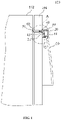
- FIG. 1 is a cross-sectional view of a refrigerator having an assist handle in an embodiment of the present invention.
- FIG. 2 is an enlarged schematic view of a region A in FIG. 1 .
- a refrigerator 100 comprises a door 101 and a cabinet 102.
- the door 101 is pivoted to the cabinet 102 and may be opened or closed relative to the cabinet 102.
- the cabinet 102 comprises a plurality of compartments for storing items.
- a front side of the door 101 is provided with a handle bar 10, an assist structure is disposed at a top end of the handle bar 10, the assist structure is located between the front side of the door 101 and the top end of the handle bar 10, and the top end of the handle bar 10 is close to the top of the refrigerator 100.
- the assist handle comprises a first lever 11, a first rotation shaft 20, a link 12, a second lever 13 and a second rotation shaft 21, wherein the first lever 11 is disposed at the top end of the handle bar 10, and preferably, the first lever 11 is integrally formed with the handle bar 10; an upper end of the first lever 11 is pivoted to the first rotation shaft 20; the second lever 13 is arranged opposite to the first lever 11, and the second lever 13 is pivoted to the second rotation shaft 21; wherein, both ends of the link 12 are pivoted to a lower end of the first lever 11 and a lower end of the second lever 13 respectively.
- the handle bar 10 and the first lever 11 pivot together around the first rotation shaft 20.
- the handle bar 10 is lifted relative to the door 101
- the first lever 11 drives the link 12 to move linearly
- the link 12 drives the second lever 13 to pivot around the second rotation shaft 21 so that the upper end of the second lever 13 pushes against a front end of a push rod 50 of the assist handle to enable the push rod 50 to move along a guide groove 60, and a distal end of the push rod 50 pushes against the cabinet 102, thereby opening and the door 101 relative to the cabinet 102.
- the guide groove 60 runs through the door 101, and the push rod 50 is inserted in the guide groove 60.
- the first lever 11, the link 12 and the second lever 13 pivoted to one another, on the one hand, extend the force arm acting on the push rod 50, and achieve a force-saving effect; on the other hand, in the case that the handle bar 10 is long (for example, the handle bar on the door of a side-by-side refrigerator), the pivotal design of the first lever 11, the link 12 and the second lever 13 allows the user to pull the handle bar by a smaller distance and avoid a phenomenon that the user needs to pull the handle bar with a large force; that is, the assist handle of the present invention is adapted for a refrigerator with a large door 101, such as a side-by-side refrigerator.
- a side of the door 101 close to the user is defined as “a front side”, and the other side away from the user is defined as “a rear side”; ends of the first lever 11 and the second lever 13 close to the top of the refrigerator 100 are defined “upper ends”, and ends close to a ground plane where the refrigerator 100 is placed are defined as “lower ends”; an end of the push rod 50 close to the user is defined as a front end, and the end far away from the user is defined as a distal end.
- the assist handle further comprises a base 30 which is configured as a box with an open end, and the open end of the box is engaged with the front side of the door 101.
- the base 30 has an upper side wall, the upper side wall is perpendicular to the door 101, the first rotation shaft 20 is disposed on a lower surface of the upper side wall, and the lower surface faces the bottom of the refrigerator 100; the second rotation shaft 21 is disposed on a surface of the front side of the door 101; the first rotation shaft 20, the second rotation shaft21, the first lever 11, the second lever 13 and the link 12 are respectively received in an internal space of the base 30.
- the link 12 is parallel and close to the lower side wall of the base 30, and the lower side wall is opposite to the upper side wall.
- the first lever 11 and the second lever 13 are respectively vertically pivoted to both ends of the link 12, so that the first lever 11, the link 12 and the second lever 13 form a U shape accommodated in the internal space of the base 30.
- Both ends of the link 12 are each provided with a first pivot structure
- the lower end of the first lever 11 and the lower end of the second lever 12 are respectively provided with a second pivot structure
- the first pivot structure is for example one of a pivot hole and a pivot shaft
- the second pivot structure is for example the other of the pivot hole and the pivot shaft.
- the lower side wall of the base 30 is provided with an escape hole corresponding to the handle bar 10, and the handle bar 10 extends out of the escape hole and is located outside the base 30, wherein the lower side wall is opposite to the upper side wall.
- the push rod 50 comprises a first rod body 51 and a second rod body 52.
- the first rod body 51 and the second rod body 52 are connected to each other by an elastic member 40.
- the elastic member 40 is for example a spring.
- the first rod body 51 is provided with a first post
- the second rod body 52 is provided with a second post
- the first post is opposite to the second post.
- Both ends of the spring are respectively sleeved on the first post and the second post, wherein the upper end of the second lever 13 abuts against a proximal end of the first rod body 51.
- the second lever 13 has a protrusion which abuts against the proximal end of the first rod body 51.
- the elastic member may further be a metal elastic piece, elastic silicone, etc.
- the push rod 50 is inserted in the guide groove 60, and the proximal end of the first rod body 51 extends out of the guide groove 60 and protrudes from the surface of the front side of the door 101, thereby facilitating the protrusion at the upper end of the second lever 13 to push against the first rod body 51.
- the elastic member 40 provides an elastic force to return the handle bar 10.
- the handle bar 10 is pulled to raise the handle bar 10 relative to the door 101.
- the handle bar 10 drives the first lever 11 to rotate counterclockwise around the first rotation shaft 20, the first lever 11 drives the link 12 to move forward horizontally and linearly, the link 12 drives the second lever 12 to rotate counterclockwise around the second rotation shaft 21 so that the protrusion at the upper end of the second rotation shaft 21 pushes against the first rod body 51, the first rod body 51 compresses the elastic member 40, the elastic member 40 pushes against the second rod body 52, and the distal end of the second rod body 52 pushes against the cabinet 102 so that the door 101 is opened; after the door 101 is opened, the distal end of the second rod body 52 abuts against the cabinet 102, the force acting upon the handle bar 10 is removed, the elastic member 40 is no longer compressed by the first rod body 51 and returns from a compressed state to an extended state to provide an elastic force, the elastic force acts on the first rod body 51
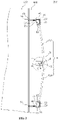
- FIG. 3 is a cross-sectional view of a refrigerator having an assist handle in another embodiment of the present invention
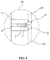
- FIG. 4 is an enlarged schematic view of a region B in FIG. 3 .
- the same reference numerals in FIG. 3 and FIG. 4 as those in FIG. 1 and FIG. 2 represent similar elements having similar functions, which will not be detailed any more.
- FIG. 3 and FIG. 4 another embodiment of the present invention provides a refrigerator 200, which is different from the refrigerator 100 in that the handle bar 10' of the refrigerator 200 is a longer rod body comprising a first handle portion 103 and a second handle portion 104, and a bottom end of the first handle portion 103 and a top end of the second handle portion 104 are connected by a connecting structure.
- the connecting structure comprises a first connector 1, a second connector 2, a fixed seat 3, a sliding groove 4, a lifting rod 5 and a lifting shaft 6, wherein the fixed seat 3 is disposed between the handle bar 10' and the door 101, and the sliding groove 4 is provided in the interior of the fixed seat 3.
- the sliding groove 4 is a through hole running through front and rear sides of the fixed seat 3.
- the lifting rod 5 is received in the sliding groove 4, a proximal end of the lifting rod 5 is provided the lifting shaft 6, the lifting hole at the distal end of the first connector 1 and the lifting hole at the distal end of the second connector 2 are respectively pivoted to the lifting shaft 6, and the first connector 1 and the second connector 2 pivoted on the on the lifting shaft 6 are arranged in a V shape.
- another lifting hole is provided at the proximal end of the lifting rod, and the mutual pivoting of the first connector, the second connector and the lifting rod is achieved by running another independent lifting shaft through the lifting hole at distal end of the first connector, the lifting hole at the distal end of the second connector and the lifting hole at the proximal end of the lifting rod.
- the proximal end of the first connector 1 is connected to the bottom end of the first handle portion 103, and the proximal end of the second connector 2 is connected to the top end of the second handle portion 104.
- the first handle portion 103 and the second handle portion 104 are simultaneously pulled. That is, when the user pulls the first handle portion 103, the first handle portion 103 is lifted toward the front side of the door 101, and the first connector 1 at the bottom end of the first handle portion 103 is driven to lift toward the front side of the door 101, the first connector 1 drives the lifting rod 5 to move along the sliding groove 4 toward the proximal end of the sliding groove 4, and at the same time, the second connector 2 at the top end of the second handle portion 104 is lifted toward the front side of the door 101, and thereby the second handle portion 104 is driven to lift toward the front side of the door 101 to realize the linkage of the first handle portion 103 and the second handle portion 104.
- an angle between the first connector 1 and the second connector 2 becomes larger.
- the above connecting structure connects the first handle portion 103 with the second handle portion 104, so that the first handle portion 103 and the second handle portion 104 are linked with each other.
- the user only needs to pull one of the first handle portion 103 and the second handle portion 104 with a small force so that the other of the first handle portion 103 and the second handle portion 104 is pulled together simultaneously.
- the connecting structure is particularly suitable for a side-by-side refrigerator with a long handle bar.
- a longitudinal section of the lifting rod 5 is a T-shaped structure
- the structure of the sliding groove 4 is adapted to the structure of the lifting rod 5
- the lifting shaft 6 is provided at a proximal end of the T-shaped structure, and a width of the proximal end of the T-shaped structure is greater than the width of its distal end.
- the refrigerator 200 employs an assist structure similar to that in the refrigerator 100. Reference may be made to the depictions of the refrigerator 100 for the assist structure. The difference lies in that the refrigerator 200 uses a pair of assist structures, namely, two assist structures.
- the pair of assist structures are respectively distributed at opposed top and bottom ends of the handle bar 10', that is, one assist structure is provided at the top end of the first handle portion 103, close to the top of the refrigerator 200; the other assist structure is disposed at the bottom end of the second handle portion 104, close to the ground plane where the refrigerator 200 is placed.
- the longer handle bar 10' in the refrigerator 200 is provided as the first handle portion 103 and the second handle portion 104 that may be linked with each other, the pair of assist structures are employed, and the pair of assist structures are provided at the top end of the first handle portion 103 and the bottom end of the second handle portion 104, respectively.
- the user can open the door 101 of the refrigerator 200 by only applying a force that can lift one handle portion of the handle bar 10'.
- the assist structure and the interlinked first handle potion 103 and second handle portion 104 may jointly achieve a better force-saving effect.
- the handle bar 10' is divided into two handle portions (the first handle portion 103 and the second handle portion 104), but the handle bar is not limited to this.
- the longer handle bar may be divided into a plurality of handle portions according to actual needs, and the plurality of handle portions are connected to one another through the above connecting structure, so that the plurality of handle portions are connected with one another by the above connecting structure so as to interlink with one another.
- the present invention provides the assist handle and a refrigerator;
- the assist structure of the assist handle employs a plurality of levers and links which are pivoted to one another; the assist structure, on the one hand, lengthens a moment arm acting on the push rod and achieves the force-saving effect; on the other hand, in the case that the handle bar is long, the distance by which the user pulls the handle bar is small, and the phenomenon that the user needs to pull the handle bar with a large force is avoided.
- the structure that the handle bar is set as a plurality of interlinked handle portions helps achieve a better force-saving effect.
Landscapes
- Engineering & Computer Science (AREA)
- Chemical & Material Sciences (AREA)
- Combustion & Propulsion (AREA)
- Physics & Mathematics (AREA)
- Mechanical Engineering (AREA)
- Thermal Sciences (AREA)
- General Engineering & Computer Science (AREA)
- Refrigerator Housings (AREA)
Applications Claiming Priority (2)
| Application Number | Priority Date | Filing Date | Title |
|---|---|---|---|
| CN201910699074.1A CN112302421B (zh) | 2019-07-31 | 2019-07-31 | 助力把手及其冰箱 |
| PCT/CN2019/111173 WO2021017178A1 (fr) | 2019-07-31 | 2019-10-15 | Poignée à assistance électrique, et réfrigérateur équipé de celle-ci |
Publications (3)
| Publication Number | Publication Date |
|---|---|
| EP4006464A1 true EP4006464A1 (fr) | 2022-06-01 |
| EP4006464A4 EP4006464A4 (fr) | 2022-09-14 |
| EP4006464B1 EP4006464B1 (fr) | 2024-11-06 |
Family
ID=74230153
Family Applications (1)
| Application Number | Title | Priority Date | Filing Date |
|---|---|---|---|
| EP19939562.5A Active EP4006464B1 (fr) | 2019-07-31 | 2019-10-15 | Poignée assistée par levier, et réfrigérateur équipé de celle-ci |
Country Status (4)
| Country | Link |
|---|---|
| EP (1) | EP4006464B1 (fr) |
| CN (1) | CN112302421B (fr) |
| AU (1) | AU2019459826B2 (fr) |
| WO (1) | WO2021017178A1 (fr) |
Families Citing this family (3)
| Publication number | Priority date | Publication date | Assignee | Title |
|---|---|---|---|---|
| CN113550655B (zh) * | 2021-06-21 | 2022-11-22 | 广东美的厨房电器制造有限公司 | 把手组件及烹饪装置 |
| CN116222071B (zh) * | 2021-12-02 | 2025-08-22 | 海信容声(广东)冰箱有限公司 | 一种冰箱 |
| CN117053471B (zh) * | 2023-08-11 | 2025-12-05 | 澳柯玛股份有限公司 | 一种开门省力的冷柜 |
Family Cites Families (19)
| Publication number | Priority date | Publication date | Assignee | Title |
|---|---|---|---|---|
| ITMI20022577A1 (it) * | 2002-12-05 | 2004-06-06 | Smeg Spa | Dispositivo di apertura di una porta di un elettrodomestico |
| JP2006250481A (ja) * | 2005-03-14 | 2006-09-21 | Sharp Corp | 把手装置及びそれを用いた冷蔵庫 |
| DE102005021540A1 (de) * | 2005-05-10 | 2006-11-16 | BSH Bosch und Siemens Hausgeräte GmbH | Scharnier zum Schwenkverschieben einer zur Seite hin zu öffnenden Tür |
| KR100880402B1 (ko) * | 2008-02-12 | 2009-02-20 | 피케이텍시스템 주식회사 | 냉장고의 도어 개방장치 |
| EP2110628A1 (fr) * | 2008-04-17 | 2009-10-21 | Electrolux Home Products N.V. | Réfrigérateur domestique |
| CN101871716B (zh) * | 2010-06-07 | 2012-11-28 | 合肥美的荣事达电冰箱有限公司 | 用于冰箱的开门装置和具有其的冰箱 |
| CN102383648B (zh) * | 2011-11-22 | 2017-02-08 | 青岛海尔特种电冰箱有限公司 | 把手、具有把手的冰箱门体及具有冰箱门体的冰箱 |
| US10550612B2 (en) * | 2015-08-20 | 2020-02-04 | Dometic Sweden Ab | Latching handle assembly |
| DE102015222738A1 (de) * | 2015-11-18 | 2017-05-18 | BSH Hausgeräte GmbH | Haushaltsgerätevorrichtung und Verfahren zum Öffnen einer Haushaltsgerätevorrichtung |
| CN105466101B (zh) * | 2015-12-25 | 2018-10-12 | 青岛海尔股份有限公司 | 具有把手的门体及冰箱 |
| CN106369920B (zh) * | 2016-10-21 | 2019-05-10 | 海信(山东)冰箱有限公司 | 一种冰箱助力门把手组件及冰箱 |
| CN106500441B (zh) * | 2016-11-01 | 2019-09-20 | 海信(山东)冰箱有限公司 | 一种冰箱助力门把手组件及冰箱 |
| CN206144272U (zh) * | 2016-11-09 | 2017-05-03 | 海信(山东)冰箱有限公司 | 一种冷藏装置及其隐藏式助力把手 |
| CN106593085B (zh) * | 2016-12-29 | 2023-05-23 | 青岛海尔特种电冰柜有限公司 | 助力把手组件及制冷设备 |
| CN206665394U (zh) * | 2017-04-24 | 2017-11-24 | 中集集团集装箱控股有限公司 | 一种连接装置 |
| CN207277989U (zh) * | 2017-08-18 | 2018-04-27 | 青岛海高设计制造有限公司 | 助力把手 |
| CN208382693U (zh) * | 2018-04-13 | 2019-01-15 | 青岛海尔特种电冰柜有限公司 | 一种冰箱助力门把手组件及冰箱 |
| CN208380376U (zh) * | 2018-04-25 | 2019-01-15 | 青岛海尔特种电冰柜有限公司 | 一种助力门把手组件及制冷设备 |
| CN109403717B (zh) * | 2018-12-29 | 2021-07-06 | Tcl家用电器(合肥)有限公司 | 把手组件及冰箱 |
-
2019
- 2019-07-31 CN CN201910699074.1A patent/CN112302421B/zh active Active
- 2019-10-15 WO PCT/CN2019/111173 patent/WO2021017178A1/fr not_active Ceased
- 2019-10-15 EP EP19939562.5A patent/EP4006464B1/fr active Active
- 2019-10-15 AU AU2019459826A patent/AU2019459826B2/en not_active Ceased
Also Published As
| Publication number | Publication date |
|---|---|
| EP4006464A4 (fr) | 2022-09-14 |
| AU2019459826B2 (en) | 2023-03-09 |
| CN112302421B (zh) | 2023-02-21 |
| AU2019459826A1 (en) | 2022-02-24 |
| WO2021017178A1 (fr) | 2021-02-04 |
| CN112302421A (zh) | 2021-02-02 |
| EP4006464B1 (fr) | 2024-11-06 |
Similar Documents
| Publication | Publication Date | Title |
|---|---|---|
| AU2019459826B2 (en) | Power-assisted handle, and refrigerator therewith | |
| EP3008408B1 (fr) | Réfrigérateur | |
| US7765645B2 (en) | Refrigerator | |
| EP3008268B1 (fr) | Dispositif de fixation | |
| KR101650307B1 (ko) | 도어핸들 및 이를 가지는 냉장고 | |
| US8152254B2 (en) | Refrigerator | |
| EP2657632A2 (fr) | Réfrigérateur et son procédé d'assemblage de poignée | |
| US20130169139A1 (en) | Refrigerator having storage container | |
| US8459759B2 (en) | Refrigerator and drawer opening/closing apparatus for the same | |
| KR20050072298A (ko) | 냉장고 | |
| KR20200009356A (ko) | 도어 개폐 장치를 포함하는 냉장고 | |
| US20100257891A1 (en) | Container of refrigerator | |
| EP4006463B1 (fr) | Poignée d'assistance et réfrigérateur la comportant | |
| KR101620399B1 (ko) | 냉장고 | |
| CN113027229B (zh) | 助力把手及其冰箱 | |
| KR101350018B1 (ko) | 냉장고 도어 개방구조 | |
| KR20110029514A (ko) | 냉장고 도어 개방장치 | |
| CN211823380U (zh) | 冷冻室门体结构及其冰箱 | |
| KR20090074442A (ko) | 냉장고의 도어 개방장치 | |
| CN218894533U (zh) | 一种新型阻尼门铰链 | |
| CN100439835C (zh) | 冰箱 | |
| CN106052269B (zh) | 一种冰箱内的小门安装结构 | |
| KR101564109B1 (ko) | 냉장고의 도어 바스켓 및 이를 포함하는 냉장고 | |
| CN206656526U (zh) | 家用器具装置和家用器具 | |
| KR100420346B1 (ko) | 냉장고 도어의 개폐장치 |
Legal Events
| Date | Code | Title | Description |
|---|---|---|---|
| STAA | Information on the status of an ep patent application or granted ep patent |
Free format text: STATUS: THE INTERNATIONAL PUBLICATION HAS BEEN MADE |
|
| PUAI | Public reference made under article 153(3) epc to a published international application that has entered the european phase |
Free format text: ORIGINAL CODE: 0009012 |
|
| STAA | Information on the status of an ep patent application or granted ep patent |
Free format text: STATUS: REQUEST FOR EXAMINATION WAS MADE |
|
| 17P | Request for examination filed |
Effective date: 20220131 |
|
| AK | Designated contracting states |
Kind code of ref document: A1 Designated state(s): AL AT BE BG CH CY CZ DE DK EE ES FI FR GB GR HR HU IE IS IT LI LT LU LV MC MK MT NL NO PL PT RO RS SE SI SK SM TR |
|
| A4 | Supplementary search report drawn up and despatched |
Effective date: 20220811 |
|
| RIC1 | Information provided on ipc code assigned before grant |
Ipc: E05B 17/00 20060101ALI20220805BHEP Ipc: F25D 23/02 20060101AFI20220805BHEP |
|
| DAV | Request for validation of the european patent (deleted) | ||
| DAX | Request for extension of the european patent (deleted) | ||
| GRAP | Despatch of communication of intention to grant a patent |
Free format text: ORIGINAL CODE: EPIDOSNIGR1 |
|
| STAA | Information on the status of an ep patent application or granted ep patent |
Free format text: STATUS: GRANT OF PATENT IS INTENDED |
|
| RIC1 | Information provided on ipc code assigned before grant |
Ipc: E05B 17/00 20060101ALI20240514BHEP Ipc: F25D 23/02 20060101AFI20240514BHEP |
|
| INTG | Intention to grant announced |
Effective date: 20240606 |
|
| GRAS | Grant fee paid |
Free format text: ORIGINAL CODE: EPIDOSNIGR3 |
|
| GRAA | (expected) grant |
Free format text: ORIGINAL CODE: 0009210 |
|
| STAA | Information on the status of an ep patent application or granted ep patent |
Free format text: STATUS: THE PATENT HAS BEEN GRANTED |
|
| AK | Designated contracting states |
Kind code of ref document: B1 Designated state(s): AL AT BE BG CH CY CZ DE DK EE ES FI FR GB GR HR HU IE IS IT LI LT LU LV MC MK MT NL NO PL PT RO RS SE SI SK SM TR |
|
| REG | Reference to a national code |
Ref country code: GB Ref legal event code: FG4D |
|
| REG | Reference to a national code |
Ref country code: CH Ref legal event code: EP |
|
| REG | Reference to a national code |
Ref country code: DE Ref legal event code: R096 Ref document number: 602019061777 Country of ref document: DE |
|
| REG | Reference to a national code |
Ref country code: IE Ref legal event code: FG4D |
|
| REG | Reference to a national code |
Ref country code: LT Ref legal event code: MG9D |
|
| REG | Reference to a national code |
Ref country code: NL Ref legal event code: MP Effective date: 20241106 |
|
| PG25 | Lapsed in a contracting state [announced via postgrant information from national office to epo] |
Ref country code: PT Free format text: LAPSE BECAUSE OF FAILURE TO SUBMIT A TRANSLATION OF THE DESCRIPTION OR TO PAY THE FEE WITHIN THE PRESCRIBED TIME-LIMIT Effective date: 20250306 Ref country code: HR Free format text: LAPSE BECAUSE OF FAILURE TO SUBMIT A TRANSLATION OF THE DESCRIPTION OR TO PAY THE FEE WITHIN THE PRESCRIBED TIME-LIMIT Effective date: 20241106 Ref country code: IS Free format text: LAPSE BECAUSE OF FAILURE TO SUBMIT A TRANSLATION OF THE DESCRIPTION OR TO PAY THE FEE WITHIN THE PRESCRIBED TIME-LIMIT Effective date: 20250306 |
|
| PG25 | Lapsed in a contracting state [announced via postgrant information from national office to epo] |
Ref country code: FI Free format text: LAPSE BECAUSE OF FAILURE TO SUBMIT A TRANSLATION OF THE DESCRIPTION OR TO PAY THE FEE WITHIN THE PRESCRIBED TIME-LIMIT Effective date: 20241106 Ref country code: NL Free format text: LAPSE BECAUSE OF FAILURE TO SUBMIT A TRANSLATION OF THE DESCRIPTION OR TO PAY THE FEE WITHIN THE PRESCRIBED TIME-LIMIT Effective date: 20241106 |
|
| REG | Reference to a national code |
Ref country code: AT Ref legal event code: MK05 Ref document number: 1739737 Country of ref document: AT Kind code of ref document: T Effective date: 20241106 |
|
| PG25 | Lapsed in a contracting state [announced via postgrant information from national office to epo] |
Ref country code: BG Free format text: LAPSE BECAUSE OF FAILURE TO SUBMIT A TRANSLATION OF THE DESCRIPTION OR TO PAY THE FEE WITHIN THE PRESCRIBED TIME-LIMIT Effective date: 20241106 |
|
| PG25 | Lapsed in a contracting state [announced via postgrant information from national office to epo] |
Ref country code: ES Free format text: LAPSE BECAUSE OF FAILURE TO SUBMIT A TRANSLATION OF THE DESCRIPTION OR TO PAY THE FEE WITHIN THE PRESCRIBED TIME-LIMIT Effective date: 20241106 |
|
| PG25 | Lapsed in a contracting state [announced via postgrant information from national office to epo] |
Ref country code: NO Free format text: LAPSE BECAUSE OF FAILURE TO SUBMIT A TRANSLATION OF THE DESCRIPTION OR TO PAY THE FEE WITHIN THE PRESCRIBED TIME-LIMIT Effective date: 20250206 |
|
| PG25 | Lapsed in a contracting state [announced via postgrant information from national office to epo] |
Ref country code: GR Free format text: LAPSE BECAUSE OF FAILURE TO SUBMIT A TRANSLATION OF THE DESCRIPTION OR TO PAY THE FEE WITHIN THE PRESCRIBED TIME-LIMIT Effective date: 20250207 Ref country code: LV Free format text: LAPSE BECAUSE OF FAILURE TO SUBMIT A TRANSLATION OF THE DESCRIPTION OR TO PAY THE FEE WITHIN THE PRESCRIBED TIME-LIMIT Effective date: 20241106 Ref country code: AT Free format text: LAPSE BECAUSE OF FAILURE TO SUBMIT A TRANSLATION OF THE DESCRIPTION OR TO PAY THE FEE WITHIN THE PRESCRIBED TIME-LIMIT Effective date: 20241106 |
|
| PG25 | Lapsed in a contracting state [announced via postgrant information from national office to epo] |
Ref country code: PL Free format text: LAPSE BECAUSE OF FAILURE TO SUBMIT A TRANSLATION OF THE DESCRIPTION OR TO PAY THE FEE WITHIN THE PRESCRIBED TIME-LIMIT Effective date: 20241106 |
|
| PG25 | Lapsed in a contracting state [announced via postgrant information from national office to epo] |
Ref country code: RS Free format text: LAPSE BECAUSE OF FAILURE TO SUBMIT A TRANSLATION OF THE DESCRIPTION OR TO PAY THE FEE WITHIN THE PRESCRIBED TIME-LIMIT Effective date: 20250206 |
|
| PG25 | Lapsed in a contracting state [announced via postgrant information from national office to epo] |
Ref country code: SM Free format text: LAPSE BECAUSE OF FAILURE TO SUBMIT A TRANSLATION OF THE DESCRIPTION OR TO PAY THE FEE WITHIN THE PRESCRIBED TIME-LIMIT Effective date: 20241106 |
|
| PG25 | Lapsed in a contracting state [announced via postgrant information from national office to epo] |
Ref country code: DK Free format text: LAPSE BECAUSE OF FAILURE TO SUBMIT A TRANSLATION OF THE DESCRIPTION OR TO PAY THE FEE WITHIN THE PRESCRIBED TIME-LIMIT Effective date: 20241106 |
|
| PG25 | Lapsed in a contracting state [announced via postgrant information from national office to epo] |
Ref country code: EE Free format text: LAPSE BECAUSE OF FAILURE TO SUBMIT A TRANSLATION OF THE DESCRIPTION OR TO PAY THE FEE WITHIN THE PRESCRIBED TIME-LIMIT Effective date: 20241106 |
|
| PG25 | Lapsed in a contracting state [announced via postgrant information from national office to epo] |
Ref country code: RO Free format text: LAPSE BECAUSE OF FAILURE TO SUBMIT A TRANSLATION OF THE DESCRIPTION OR TO PAY THE FEE WITHIN THE PRESCRIBED TIME-LIMIT Effective date: 20241106 |
|
| PG25 | Lapsed in a contracting state [announced via postgrant information from national office to epo] |
Ref country code: SK Free format text: LAPSE BECAUSE OF FAILURE TO SUBMIT A TRANSLATION OF THE DESCRIPTION OR TO PAY THE FEE WITHIN THE PRESCRIBED TIME-LIMIT Effective date: 20241106 |
|
| PG25 | Lapsed in a contracting state [announced via postgrant information from national office to epo] |
Ref country code: CZ Free format text: LAPSE BECAUSE OF FAILURE TO SUBMIT A TRANSLATION OF THE DESCRIPTION OR TO PAY THE FEE WITHIN THE PRESCRIBED TIME-LIMIT Effective date: 20241106 |
|
| PG25 | Lapsed in a contracting state [announced via postgrant information from national office to epo] |
Ref country code: IT Free format text: LAPSE BECAUSE OF FAILURE TO SUBMIT A TRANSLATION OF THE DESCRIPTION OR TO PAY THE FEE WITHIN THE PRESCRIBED TIME-LIMIT Effective date: 20241106 |
|
| REG | Reference to a national code |
Ref country code: DE Ref legal event code: R097 Ref document number: 602019061777 Country of ref document: DE |
|
| PG25 | Lapsed in a contracting state [announced via postgrant information from national office to epo] |
Ref country code: SE Free format text: LAPSE BECAUSE OF FAILURE TO SUBMIT A TRANSLATION OF THE DESCRIPTION OR TO PAY THE FEE WITHIN THE PRESCRIBED TIME-LIMIT Effective date: 20241106 |
|
| PLBE | No opposition filed within time limit |
Free format text: ORIGINAL CODE: 0009261 |
|
| STAA | Information on the status of an ep patent application or granted ep patent |
Free format text: STATUS: NO OPPOSITION FILED WITHIN TIME LIMIT |
|
| 26N | No opposition filed |
Effective date: 20250807 |
|
| PGFP | Annual fee paid to national office [announced via postgrant information from national office to epo] |
Ref country code: DE Payment date: 20251015 Year of fee payment: 7 |
|
| PGFP | Annual fee paid to national office [announced via postgrant information from national office to epo] |
Ref country code: GB Payment date: 20251023 Year of fee payment: 7 |
|
| PGFP | Annual fee paid to national office [announced via postgrant information from national office to epo] |
Ref country code: FR Payment date: 20251027 Year of fee payment: 7 |