EP4006478B1 - Échangeur de chaleur de type à paroi de séparation - Google Patents
Échangeur de chaleur de type à paroi de séparation Download PDFInfo
- Publication number
- EP4006478B1 EP4006478B1 EP20846809.0A EP20846809A EP4006478B1 EP 4006478 B1 EP4006478 B1 EP 4006478B1 EP 20846809 A EP20846809 A EP 20846809A EP 4006478 B1 EP4006478 B1 EP 4006478B1
- Authority
- EP
- European Patent Office
- Prior art keywords
- flow path
- path wall
- numbered
- bulkhead
- heat exchanger
- Prior art date
- Legal status (The legal status is an assumption and is not a legal conclusion. Google has not performed a legal analysis and makes no representation as to the accuracy of the status listed.)
- Active
Links
Images


Classifications
-
- F—MECHANICAL ENGINEERING; LIGHTING; HEATING; WEAPONS; BLASTING
- F28—HEAT EXCHANGE IN GENERAL
- F28D—HEAT-EXCHANGE APPARATUS, NOT PROVIDED FOR IN ANOTHER SUBCLASS, IN WHICH THE HEAT-EXCHANGE MEDIA DO NOT COME INTO DIRECT CONTACT
- F28D9/00—Heat-exchange apparatus having stationary plate-like or laminated conduit assemblies for both heat-exchange media, the media being in contact with different sides of a conduit wall
- F28D9/0062—Heat-exchange apparatus having stationary plate-like or laminated conduit assemblies for both heat-exchange media, the media being in contact with different sides of a conduit wall the conduits for one heat-exchange medium being formed by spaced plates with inserted elements
-
- F—MECHANICAL ENGINEERING; LIGHTING; HEATING; WEAPONS; BLASTING
- F28—HEAT EXCHANGE IN GENERAL
- F28F—DETAILS OF HEAT-EXCHANGE AND HEAT-TRANSFER APPARATUS, OF GENERAL APPLICATION
- F28F3/00—Plate-like or laminated elements; Assemblies of plate-like or laminated elements
- F28F3/02—Elements or assemblies thereof with means for increasing heat-transfer area, e.g. with fins, with recesses, with corrugations
- F28F3/06—Elements or assemblies thereof with means for increasing heat-transfer area, e.g. with fins, with recesses, with corrugations the means being attachable to the element
-
- F—MECHANICAL ENGINEERING; LIGHTING; HEATING; WEAPONS; BLASTING
- F28—HEAT EXCHANGE IN GENERAL
- F28D—HEAT-EXCHANGE APPARATUS, NOT PROVIDED FOR IN ANOTHER SUBCLASS, IN WHICH THE HEAT-EXCHANGE MEDIA DO NOT COME INTO DIRECT CONTACT
- F28D9/00—Heat-exchange apparatus having stationary plate-like or laminated conduit assemblies for both heat-exchange media, the media being in contact with different sides of a conduit wall
- F28D9/0031—Heat-exchange apparatus having stationary plate-like or laminated conduit assemblies for both heat-exchange media, the media being in contact with different sides of a conduit wall the conduits for one heat-exchange medium being formed by paired plates touching each other
- F28D9/0043—Heat-exchange apparatus having stationary plate-like or laminated conduit assemblies for both heat-exchange media, the media being in contact with different sides of a conduit wall the conduits for one heat-exchange medium being formed by paired plates touching each other the plates having openings therein for circulation of at least one heat-exchange medium from one conduit to another
- F28D9/005—Heat-exchange apparatus having stationary plate-like or laminated conduit assemblies for both heat-exchange media, the media being in contact with different sides of a conduit wall the conduits for one heat-exchange medium being formed by paired plates touching each other the plates having openings therein for circulation of at least one heat-exchange medium from one conduit to another the plates having openings therein for both heat-exchange media
-
- F—MECHANICAL ENGINEERING; LIGHTING; HEATING; WEAPONS; BLASTING
- F28—HEAT EXCHANGE IN GENERAL
- F28D—HEAT-EXCHANGE APPARATUS, NOT PROVIDED FOR IN ANOTHER SUBCLASS, IN WHICH THE HEAT-EXCHANGE MEDIA DO NOT COME INTO DIRECT CONTACT
- F28D9/00—Heat-exchange apparatus having stationary plate-like or laminated conduit assemblies for both heat-exchange media, the media being in contact with different sides of a conduit wall
- F28D9/02—Heat-exchange apparatus having stationary plate-like or laminated conduit assemblies for both heat-exchange media, the media being in contact with different sides of a conduit wall the heat-exchange media travelling at an angle to one another
-
- F—MECHANICAL ENGINEERING; LIGHTING; HEATING; WEAPONS; BLASTING
- F28—HEAT EXCHANGE IN GENERAL
- F28F—DETAILS OF HEAT-EXCHANGE AND HEAT-TRANSFER APPARATUS, OF GENERAL APPLICATION
- F28F13/00—Arrangements for modifying heat-transfer, e.g. increasing, decreasing
- F28F13/06—Arrangements for modifying heat-transfer, e.g. increasing, decreasing by affecting the pattern of flow of the heat-exchange media
- F28F13/08—Arrangements for modifying heat-transfer, e.g. increasing, decreasing by affecting the pattern of flow of the heat-exchange media by varying the cross-section of the flow channels
-
- F—MECHANICAL ENGINEERING; LIGHTING; HEATING; WEAPONS; BLASTING
- F28—HEAT EXCHANGE IN GENERAL
- F28F—DETAILS OF HEAT-EXCHANGE AND HEAT-TRANSFER APPARATUS, OF GENERAL APPLICATION
- F28F3/00—Plate-like or laminated elements; Assemblies of plate-like or laminated elements
- F28F3/02—Elements or assemblies thereof with means for increasing heat-transfer area, e.g. with fins, with recesses, with corrugations
- F28F3/025—Elements or assemblies thereof with means for increasing heat-transfer area, e.g. with fins, with recesses, with corrugations the means being corrugated, plate-like elements
- F28F3/027—Elements or assemblies thereof with means for increasing heat-transfer area, e.g. with fins, with recesses, with corrugations the means being corrugated, plate-like elements with openings, e.g. louvered corrugated fins; Assemblies of corrugated strips
-
- F—MECHANICAL ENGINEERING; LIGHTING; HEATING; WEAPONS; BLASTING
- F28—HEAT EXCHANGE IN GENERAL
- F28F—DETAILS OF HEAT-EXCHANGE AND HEAT-TRANSFER APPARATUS, OF GENERAL APPLICATION
- F28F3/00—Plate-like or laminated elements; Assemblies of plate-like or laminated elements
- F28F3/08—Elements constructed for building-up into stacks, e.g. capable of being taken apart for cleaning
-
- F—MECHANICAL ENGINEERING; LIGHTING; HEATING; WEAPONS; BLASTING
- F28—HEAT EXCHANGE IN GENERAL
- F28F—DETAILS OF HEAT-EXCHANGE AND HEAT-TRANSFER APPARATUS, OF GENERAL APPLICATION
- F28F9/00—Casings; Header boxes; Auxiliary supports for elements; Auxiliary members within casings
- F28F9/22—Arrangements for directing heat-exchange media into successive compartments, e.g. arrangements of guide plates
-
- F—MECHANICAL ENGINEERING; LIGHTING; HEATING; WEAPONS; BLASTING
- F28—HEAT EXCHANGE IN GENERAL
- F28F—DETAILS OF HEAT-EXCHANGE AND HEAT-TRANSFER APPARATUS, OF GENERAL APPLICATION
- F28F9/00—Casings; Header boxes; Auxiliary supports for elements; Auxiliary members within casings
- F28F9/24—Arrangements for promoting turbulent flow of heat-exchange media, e.g. by plates
Definitions
- WO 2019/167491 A1 which is considered as comprised in the state of the art pursuant to Article 54(3) EPC, discloses bulkhead heat exchangers as in the first to third examples described below.
- the present invention is made in consideration of the above circumstances, and an object thereof is to provide a bulkhead heat exchanger including a heat transfer surface having a shape which improves heat transfer performance while achieving a compact heat exchanger.
- the object is achieved by providing a bulkhead heat exchanger as specified in claim 1 or a bulkhead heat exchanger as specified in claim 4.
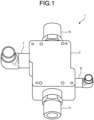
- FIG. 1 is a perspective view illustrating a bulkhead heat exchanger 1 of a first example outside the terms of the claims.
- the bulkhead heat exchanger 1 according to the first example includes a heat exchanger body 2, a first inflow pipe 5, a first outflow pipe 6, a second inflow pipe 7, and a second outflow pipe 8, as illustrated in FIG. 1 .
- a first fluid flows into the heat exchanger body 2 through the first inflow pipe 5.
- the first fluid which has been heat-exchanged with a second fluid in the heat exchanger body 2 flows from the heat exchanger body 2 to the outside through the first outflow pipe 6.
- the second fluid flows into the heat exchanger body 2 through the second inflow pipe 7.
- the second fluid which has been heat-exchanged with the first fluid in the heat exchanger body 2, flows from the heat exchanger body 2 to the outside through the second outflow pipe 8.
- FIG. 2 is an exploded perspective view illustrating the heat exchanger body 2.
- the heat exchanger body 2 of FIG. 2 is a view in which the bulkhead heat exchanger 1 of FIG. 1 is rotated by 180° about a pipe axis of the second inflow pipe 7 or the second outflow pipe 8.
- the heat exchanger body 2 includes a laminated body 10, a first end plate 11, and a second end plate 12.
- the laminated body 10 is formed into a columnar body.
- the first end plate 11 covers one bottom surface S1 of the laminated body 10 which is a columnar body, and is fixed to the laminated body 10.
- the second end plate 12 covers the other bottom surface S2 on a side opposite to the bottom surface S1 of the laminated body 10 which is a columnar body and is fixed to the laminated body 10.
- the laminated body 10 further includes a first outflow hole 18 and a second outflow hole 19.
- the first outflow hole 18 is formed on a side surface near the first outflow chamber 15 among side surfaces of the laminated body 10, and connects the first outflow chamber 15 and the outside of the heat exchanger body 2 to each other.
- the first outflow pipe 6 one end thereof is fixed to the laminated body 10 to be inserted into the first outflow hole 18 and to face the first outflow chamber 15, and the other end thereof is disposed outside the heat exchanger body 2.
- the second outflow hole 19 is formed on a side surface near the second outflow chamber 17 among the side surfaces of the laminated body 10, and connects the inside of the second outflow chamber 17 and the outside of the heat exchanger body 2 to each other.
- the second outflow pipe 8 one end thereof is fixed to the laminated body 10 to be inserted into the second outflow hole 19 and to face the second outflow chamber 17, and the other end thereof is disposed outside the heat exchanger body 2.
- the laminated body 10 further includes a first inflow hole (not illustrated) and a second inflow hole (not illustrated).
- the first inflow hole is formed on a side surface near the first inflow chamber 14 among the side surfaces of the laminated body 10, and connects the inside of the first inflow chamber 14 and the outside of the heat exchanger body 2 to each other.
- one end thereof is fixed to the laminated body 10 to be inserted into the first inflow hole and to face the first inflow chamber 14, and the other end thereof is disposed outside the heat exchanger body 2.
- the second inflow hole is formed on a side surface near the second inflow chamber 16 among the side surfaces of the laminated body 10, and connects the inside of the second inflow chamber 16 and the outside of the heat exchanger body 2 to each other.
- one end thereof is fixed to the laminated body 10 to be inserted into the second inflow hole and to face the second inflow chamber 16, and the other end thereof is disposed outside the heat exchanger body 2.
- the laminated body 10 has a plurality of heat exchanger plates. Each of the plurality of heat exchanger plates is formed in a plate shape. The plurality of heat exchanger plates are disposed perpendicular to the lamination direction 20 and are laminated so as to be in close contact with each other. The plurality of heat exchanger plates have a plurality of first heat exchanger plates and a plurality of second heat exchanger plates. The first heat exchanger plate and the second heat exchanger plate are alternately laminated.
- FIG. 3 is a plan view illustrating one first heat exchanger plate 21 of the plurality of first heat exchanger plates.
- the first heat exchanger plate 21 includes a first inflow chamber hole 22, a first outflow chamber hole 23, a second inflow chamber hole 24, and a second outflow chamber hole 25.
- Each of the first inflow chamber hole 22, the first outflow chamber hole 23, the second inflow chamber hole 24, and the second outflow chamber hole 25 penetrate the first heat exchanger plate 21 from one surface S3 of the first heat exchanger plate 21 to the other surface S4 thereof.
- a first heat exchange flow path recess 26 is formed in substantially a center of the first heat exchanger plate 21.
- the first inflow flow path recess 27 is formed between the first heat exchange flow path recess 26 and the first inflow chamber hole 22, is connected to the first inflow chamber hole 22, and is connected to an edge V1 of the first heat exchange flow path recess 26 on a side of the first inflow chamber hole 22.
- the first inflow chamber hole 32 is connected to the first inflow chamber hole 22 of the first heat exchanger plate 21 to form the first inflow chamber 14 when the plurality of heat exchanger plates are appropriately laminated.
- the first outflow chamber hole 33 is connected to the first outflow chamber hole 23 of the first heat exchanger plate 21 to form the first outflow chamber 15 when the plurality of heat exchanger plates are appropriately laminated.
- the second inflow chamber hole 34 is connected to the second inflow chamber hole 24 of the first heat exchanger plate 21 to form the second inflow chamber 16 when the plurality of heat exchanger plates are appropriately laminated.
- the second outflow chamber hole 35 is connected to the second outflow chamber hole 25 of the first heat exchanger plate 21 to form the second outflow chamber 17 when the plurality of heat exchanger plates are appropriately laminated.
- the second heat exchanger plate 31 further includes a second heat exchange flow path recess 36, a second inflow flow path recess 37, and a second outflow flow path recess 38 which are formed on one surface S5.
- the second heat exchange flow path recess 36 is formed in substantially a center of the second heat exchanger plate 31 so as to overlap the first heat exchange flow path recess 26 of the first heat exchanger plate 21 in the lamination direction 20 when the plurality of heat exchanger plates are appropriately laminated.
- the second inflow flow path recess 37 is formed between the second inflow chamber hole 34 and the second heat exchange flow path recess 36, is connected to the second inflow chamber hole 34, and is connected to an edge V3 of the second heat exchange flow path recess 36 on a side of the first outflow chamber hole 33.
- the second outflow flow path recess 38 is formed between the second outflow chamber hole 35 and the second heat exchange flow path recess 36, is connected to the second outflow chamber hole 35, and is connected to an edge V4 of the second heat exchange flow path recess 36 on a side opposite to the edge V3 connected to the second inflow flow path recess 37 in a flow direction 29.
- the flow direction 29 is the same as the flow direction 29 of FIG. 3 .
- the flow direction 29 represents a direction (a traveling direction of the second fluid flowing along the sinusoidal flow path described later) in which the second fluid as a whole flows through the second heat exchange flow path recess 36, and the flow direction 29 is perpendicular to the lamination direction 20, that is, is parallel to the second heat exchanger plate 31. Since the flow directions of the first fluid and the second fluid are reversible, the flow direction 29 is indicated by a double-headed arrow in FIGS. 3 and 4 .
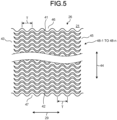
- FIG. 5 is a plan view illustrating the first heat exchange flow path recess 26.
- the first heat exchange flow path recess 26 is formed, and thus, a first sidewall surface 41, a second sidewall surface 42, and a bottom surface 43 are formed.
- the first sidewall surface 41 is formed on one edge of the first heat exchange flow path recess 26 in a span direction 44 and forms a portion of an inner wall surface of the first heat exchange flow path recess 26.
- the span direction 44 is perpendicular to the lamination direction 20 and perpendicular to the flow direction 29.
- the span direction 44 is an amplitude direction of a sine curve 51 to be described later.
- variable x indicates a position in the flow direction 29.
- variable y indicates a position in the span direction 44.
- the amplitude A is exemplified by a value smaller than 1.0 mm, for example, 0.6 mm.
- the period T is 3 mm.
- the second sidewall surface 42 is formed at an edge of the first heat exchange flow path recess 26 on a side opposite to the edge where the first sidewall surface 41 is formed in the span direction 44, and forms a portion of the inner wall surface of the first heat exchange flow path recess 26.
- the second sidewall surface 42 is substantially perpendicular to the plane to which the first heat exchanger plate 21 conforms, that is, substantially parallel to the lamination direction 20.
- the second sidewall surface 42 is formed so as to conform to a sine curve drawn on a plane to which the first heat exchanger plate 21 conforms.
- the sine curve to which the second sidewall surface 42 conforms is the same sine curve to which the first sidewall surface 41 conforms.
- the bottom surface 43 forms a portion of the inner wall surface of the first heat exchange flow path recess 26, and forms a surface interposed between the first sidewall surface 41 and the second sidewall surface 42 among the inner wall surfaces of the first heat exchange flow path recess 26.
- the bottom surface 43 is formed to be parallel to the plane to which the first heat exchanger plate 21 is parallel.
- the first heat exchanger plate 21 includes a first bulkhead 45, a first sidewall 46, a second sidewall 47, and a plurality of first flow path walls 48-1 to 48-n (n is a positive integer, and hereinafter, in other examples and in the embodiments as well, n represents an arbitrary positive integer).
- the first bulkhead 45 is a portion which forms a bottom of the first heat exchange flow path recess 26, that is, forms the bottom surface 43 of the first heat exchanger plate 21.
- the first sidewall 46 is a portion which forms one sidewall of the first heat exchange flow path recess 26, that is, forms the first sidewall surface 41 of the first heat exchanger plate 21.
- FIG. 6 is a plan view illustrating two adjacent flow path walls of the plurality of first flow path walls 48-1 to 48-n.
- one first flow path wall 48-1 of the plurality of first flow path walls 48-1 to 48-n is formed to conform to a sine curve 51 drawn on the plane parallel to the first heat exchanger plate 21.
- the sine curve 51 is the same as the sine curve to which the first sidewall surface 41 or the second sidewall surface 42 represented by Equation (1) conforms, and is formed so that an amplitude thereof is periodically and smoothly changed in the flow direction 29.
- the period of the sine curve 51 is equal to the period T of the sine curve to which the first sidewall surface 41 or the second sidewall surface 42 conforms
- the amplitude of the sine curve 51 is equal to the amplitude A of the sine curve to which the first sidewall surface 41 or the second sidewall surface 42 conforms.
- the first flow path wall 48-1 forms a first side flow path wall surface 52 and a second side flow path wall surface 53.
- the first side flow path wall surface 52 is formed on the first flow path wall 48-1 on the side of the first sidewall 46.
- the first side flow path wall surface 52 is formed so as to conform to a sine curve (corresponding to a "first sine curve") drawn on the plane parallel to the first heat exchanger plate 21.
- the sine curve to which the first side flow path wall surface 52 conforms is the same as the sine curve 51 and is formed to overlap a sine curve which is disposed by translating the sine curve 51 by an offset value y 0 to the side of the first sidewall 46 in the span direction (corresponding to the "amplitude direction of the sine curve 51") 44.
- the offset value y 0 is 0.1 mm.
- the second side flow path wall surface 53 is formed on the first flow path wall 48-1 on the side of the second sidewall 47.
- the second side flow path wall surface 53 is formed to overlap a sine curve (corresponding to a "second sine curve") which is disposed by translating the sine curve 51 by an offset value y 0 to the side of the second sidewall 47 in the span direction 44.
- the first side flow path wall surface 52 and the second side flow path wall surface 53 are substantially perpendicular to the plane to which the first heat exchanger plate 21 conforms, that is, substantially parallel to the lamination direction 20.
- the first flow path wall 48-1 is formed in this way.
- a width w 1 of a portion (a portion orthogonal to the sine curve 51 at the inflection point) of the first flow path wall 48-1 which overlaps the inflection point of the sine curve 51 is narrower than a width w 2 of a portion of the first flow path wall 48-1 which overlaps a maximum point or a minimum point of the sine curve 51.
- the inflection point of the sine curve 51 represented by Equation (1) corresponds to a point on the graph of the sine function having a phase ⁇ represented by the following Equation (2) as the inflection point using the integer i (hereinafter, i represents an arbitrary integer in other examples and in the embodiments as well).
- ⁇ ⁇ i
- the maximum point of the sine curve 51 corresponds to a point of a graph of a sine function corresponding to a phase ⁇ represented by the following Equation (3).
- ⁇ ⁇ / 2 + 2 ⁇ i
- the minimum point of the sine curve 51 corresponds to a point of a graph of a sine function corresponding to a phase ⁇ represented by the following Equation (4).
- ⁇ 3 ⁇ / 2 + 2 ⁇ i
- the adjacent first flow path wall 48-2 disposed on the side of the second sidewall 47 of the first flow path wall 48-1 among the plurality of first flow path walls 48-1 to 48-n is formed similarly to the first flow path wall 48-1. That is, the first flow path wall 48-2 is formed so as to conform to the sine curve 51, and includes the first side flow path wall surface 52 and the second side flow path wall surface 53. Moreover, the first flow path wall 48-2 is disposed so that the sine curve 51 to which the first flow path wall 48-2 conforms overlaps a sine curve disposed by translating the sine curve 51 to which the first flow path wall 48-1 conforms by a predetermined pitch P in the span direction 44. For example, the pitch P is 0.75 mm.
- the first heat exchanger plate 21 has a plurality of grooves formed by forming the plurality of first flow path walls 48-1 to 48-n.
- Each groove 57 is formed between two adjacent first flow path walls of the plurality of first flow path walls 48-1 to 48-n, and is formed between the first side flow path wall surface 52 of one first flow path wall and the second side flow path wall surface 53 of the other first flow path wall.
- the first side flow path wall surface 52 and the second side flow path wall surface 53 conform to the same sine curve. Accordingly, the groove 57 is formed so that a width w 3 of a portion close to the inflection point of the sine curve 51 is narrower than a width w 4 of a portion close to the maximum point or the minimum point of the sine curve 51.
- the second heat exchange flow path recesses 36 of the second heat exchanger plate 31 are formed similarly to the first heat exchange flow path recesses 26 of the first heat exchanger plate 21.
- FIG. 7 is an enlarged cross-sectional view taken along line A-A of FIG. 2 .
- the second heat exchanger plate 31 includes a second bulkhead 61 and a plurality of second flow path walls 62-1 to 62-n.
- the second bulkhead 61 forms a bottom of the second heat exchange flow path recess 36, that is, a bottom surface 63 parallel to the second heat exchanger plate 31.
- the two sidewalls are respectively formed on both ends of the second heat exchange flow path recess 36 in the span direction 44 and respectively form two sidewall surfaces excluding the bottom surface 63 among inner wall surfaces of the second heat exchange flow path recess 36.
- one surface S3 of the first heat exchanger plate 21 is joined to the other surface S6 of the second heat exchanger plate 31, one surface S5 of the second heat exchanger plate 31 is joined to the other surface S4 of the first heat exchanger plate 21, and thus, the plurality of heat exchanger plates are laminated. That is, the laminated body 10 is formed by joining the plurality of heat exchanger plates to each other in a state where the first heat exchanger plates 21 and the second heat exchanger plates 31 are alternately laminated in this way.
- the plurality of second flow path walls 62-1 to 62-n are formed to overlap the plurality of first flow path walls 48-1 to 48-n in the lamination direction 20 when the plurality of heat exchanger plates are appropriately laminated.
- Tops S7 of the plurality of first flow path walls 48-1 to 48-n are joined to the other surface S6 of the second bulkhead 61 and tops S8 of the plurality of second flow path walls 62-1 to 62-n are joined to the other surface S4 of the first bulkhead 45.
- the first sidewall 46 and the second sidewall 47 of the first heat exchanger plate 21 are formed to respectively overlap two sidewalls of the second heat exchanger plate 31 in the lamination direction 20 when a plurality of heat exchanger plates are appropriately laminated.
- a plurality of heat exchanger plates are laminated to form a plurality of first spaces 67 and a plurality of second spaces 68.
- the first space 67 is a space which is located inside the first heat exchange flow path recess 26 of the first heat exchanger plate 21 and is formed between the first bulkhead 45 and the second bulkhead 61.
- the plurality of first flow path walls 48-1 to 48-n divide the first space 67 inside the first heat exchange flow path recess 26 into a plurality of first flow paths 65.
- the plurality of first flow paths 65 include a plurality of flow paths surrounded by the plurality of first flow path walls 48-1 to 48-n, the first bulkhead 45, and the second bulkhead 61.
- the plurality of first flow paths 65 further include a flow path surrounded by the first sidewall 46, one flow path wall 48-1, the first bulkhead 45, and the second bulkhead 61, and a flow path surrounded by the second sidewall 47, one flow path wall 48-n, the first bulkhead 45, and the second bulkhead 61.
- the second space 68 is a space which is located inside the second heat exchange flow path recess 36 of the second heat exchanger plate 31 and is formed between the first bulkhead 45 and the second bulkhead 61.
- the plurality of second flow path walls 62-1 to 62-n divide the second space 68 inside the second heat exchange flow path recess 36 into a plurality of second flow paths 66.
- the plurality of second flow paths 66 include a plurality of flow paths surrounded by the plurality of second flow path walls 62-1 to 62-n, the first bulkhead 45, and the second bulkhead 61.
- the plurality of second flow paths 66 further includes a flow path which is surrounded by one of the two sidewalls, one flow path wall of the plurality of second flow path walls 62-1 to 62-n, the first bulkhead 45, and the second bulkhead 61, and a flow path which is surrounded by the other of the two sidewalls, one flow path wall of the plurality of second flow path walls 62-1 to 62-n, the first bulkhead 45, and the second bulkhead 61.
- the first flow path 65 and the second flow path 66 form a sinusoidal flow path in which the fluid flows with the flow direction 29 as the traveling direction while repeating vibrations in the span direction 44.
- a width of the groove 57 formed between the first side flow path wall surface 52 and the second side flow path wall surface 53 is changed depending on a position along the flow path. Accordingly, a cross-sectional area of the first flow path 65 is changed depending on the position along the flow path.
- the second flow path 66 also has a different cross-sectional area depending on the position. The cross-sectional areas of the first flow path 65 and the second flow path 66 periodically repeat enlargement and reduction depending on positions along the respective flow paths.
- the minimum first flow path width Wc1 is the minimum value of the intervals of the plurality of first flow path walls 48-1 to 48-n, and indicates the minimum value of the distances between two adjacent flow path walls among the plurality of first flow path walls 48-1 to 48-n, that is, the minimum value of the widths of the first flow path 65.
- the first flow path wall height H1 indicates the interval between the first bulkhead 45 and the second bulkhead 61, indicates a depth of the first heat exchange flow path recess 26, and indicates heights of the plurality of first flow path walls 48-1 to 48-n, that is, a height of the first flow path 65 in the lamination direction 20.
- the second flow path 66 is formed so that the following Equation (6) is established using a minimum second flow path width Wc2 and a second flow path wall height H2. 2.5 ⁇ Wc 2 / H 2 ⁇ 6
- the minimum second flow path width Wc2 is the minimum value of the intervals of the plurality of second flow path walls 62-1 to 62-n, and indicates the minimum value of the distances between two adjacent flow path walls among the plurality of second flow path walls 62-1 to 62-n, that is, the minimum value of the widths of the second flow path 66.
- the second flow path wall height H2 indicates the interval between the first bulkhead 45 and the second bulkhead 61, indicates a depth of the second heat exchange flow path recess 36, and indicates heights of the plurality of second flow path walls 62-1 to 62-n, that is, a height of the second flow path 66 in the lamination direction 20.
- Wc1/H1 and Wc2/H2 are less than 6.
- Wc1/H1 and Wc2/H2 are larger than 2.5 and smaller than 6. Accordingly, it is possible to suppress a decrease in heat transfer performance of heat transfer between the first fluid and the second fluid, and the first bulkhead 45 and the second bulkhead 61, and it is possible to suppress a decrease in pressure resistance performance.
- the design parameters are tuned according to an operating condition of a working fluid.
- a plurality of mathematical models of the bulkhead heat exchanger 1 in which the shapes of the plurality of first flow paths 65 and the plurality of second flow paths 66 are different are created.
- the plurality of mathematical models are used for computer simulation, and are used for calculating a behavior of the fluid flowing through the plurality of first flow paths 65 and the plurality of second flow paths 66 and the heat transfer performance of the heat exchanger.
- the bulkhead heat exchanger 1 is designed such that the plurality of first flow paths and the plurality of second flow paths are formed to have appropriate shapes based on the behavior of the fluid and the heat transfer performance of the heat exchanger calculated.
- the first side flow path wall surface 52 and the second side flow path wall surface 53 conform to a simple sine curve. Accordingly, it is possible to perform a computer simulation for determining the shapes of the plurality of first flow paths 65 and the plurality of second flow paths 66 with a small number of parameters.
- the parameters the period T, the amplitude A, the offset value y 0 , and the pitch P are exemplified.
- the number of parameters which determine the shapes of the plurality of first flow paths 65 and the plurality of second flow paths 66 decreases. Accordingly, it is possible to decrease an amount of calculation of the computer when executing the computer simulation, and it is possible to shorten a time for computer simulation. Therefore, in the bulkhead heat exchanger 1, it is possible to easily perform an operation for optimizing the shapes of the plurality of first flow path walls 48-1 to 48-n and the plurality of second flow path walls 62-1 to 62-n by computer simulation.
- the first outflow hole 18, the second outflow hole 19, the first inflow hole, and the second inflow hole are formed by machining after the first end plate 11, the second end plate 12, and the plurality of laminated heat exchanger plates are joined to each other.
- the first inflow pipe 5, the first outflow pipe 6, the second inflow pipe 7, and the second outflow pipe 8 are fixed to the heat exchanger body 2 by welding after being respectively inserted into the first inflow hole, the first outflow hole 18, the second inflow hole, and the second outflow hole 19.
- the first side flow path wall surface 52 and the second side flow path wall surface 53 conform to the sine curve, and thus, the flow direction of the first fluid is changed in a sinusoidal manner.
- the flow direction of the first fluid is sharply changed compared to the other portions, and thus, the portion receives a large stress from the first fluid.
- the width of the flow path wall is largely formed compared to the other portions.
- the cross-sectional areas of the plurality of first flow paths 65 are changed depending on the positions in the flow direction along the flow paths, and thus, a flow speed of the first fluid is changed.
- the flow direction is changed in a sinusoidal manner and the flow speed is changed, and thus, the first fluid is always disturbed locally.
- the first fluid is always disturbed locally. Therefore, it is possible to reduce a thermal resistance of heat transfer between the first fluid and the first bulkhead 45 and reduce a thermal resistance of heat transfer between the first fluid and the second bulkhead 61.
- the second fluid flows into the second inflow chamber 16 via the second inflow pipe 7.
- the second fluid is distributed to the plurality of second heat exchanger plates 31 and flows into the second inflow flow path recess 37 formed in the second heat exchanger plate 31.
- a width of the second fluid flowing through the second inflow flow path recess 37 is expanded from the width of the second inflow chamber 16 to the width of the second heat exchange flow path recess 36, and thus, the second fluid flows into the plurality of second flow paths 66 formed in the second heat exchange flow path recess 36.
- the second fluid flows through the plurality of second flow paths 66, the cross-sectional areas of the plurality of second flow paths 66 are changed depending on the positions in the flow direction along the flow paths, and thus, a flow speed of the second fluid is changed.
- the second fluid flows through the plurality of second flow paths 66, the flow direction is changed in a sinusoidal manner and the flow speed is changed, and thus, the second fluid is always disturbed locally.
- the second fluid is always disturbed locally. Therefore, it is possible to reduce a thermal resistance of heat transfer between the second fluid and the first bulkhead 45 and reduce a thermal resistance of heat transfer between the second fluid and the second bulkhead 61.
- the thermal resistance of heat transfer between the first fluid and the second fluid, and the first bulkhead 45 and the second bulkhead 61 is reduced. Accordingly, it is possible to improve performance of the heat exchange performed between the first fluid and the second fluid.
- the plurality of first side flow path wall surfaces 52 and the plurality of second side flow path wall surfaces 53 conforming to the sine curves are formed. Accordingly, the flow direction of the first fluid flowing through the plurality of first flow paths 65 can be changed in a sinusoidal manner.
- the plurality of first side flow path wall surfaces 52 and the plurality of second side flow path wall surfaces 53 conforming to the sine curve are formed. Accordingly, the widths of the plurality of first flow paths 65 can be changed along the direction in which the first fluid flows. In the bulkhead heat exchanger 1, the widths of the plurality of first flow paths 65 are changed.
- the bulkhead heat exchanger 1 of the first example further includes the first sidewall 46 in which the first sidewall surface 41 formed at the end of the first space 67 inside the first heat exchange flow path recess 26 is formed.
- the first sidewall surface 41 is formed so as to conform to the same sine curve as the sine curve to which the plurality of first side flow path wall surfaces 52 and the plurality of second side flow path wall surfaces 53 conform.
- the period of the sine curve to which the first sidewall surface 41 conforms is equal to the period of the sine curve to which the plurality of first side flow path wall surfaces 52 and the plurality of second side flow path wall surfaces 53 conform
- the amplitude of the sine curve to which the first sidewall surface 41 conforms is equal to the amplitude of the sine curve to which the plurality of first side flow path wall surfaces 52 and the plurality of second side flow path wall surfaces 53 conform.
- the bulkhead heat exchanger 1 similarly to the first fluid flowing through the flow path interposed between the plurality of first flow path walls 48-1 to 48-n, it is possible to always disturb locally the first fluid flowing through the flow path formed between the first flow path wall 48-1 and the first sidewall surface 41. As a result, in the bulkhead heat exchanger 1, the first fluid is always disturbed locally, and thus, it is possible to further improve the heat transfer performance when the heat exchange is performed between the first fluid and the second fluid.
- FIG. 8 is a plan view illustrating the plurality of odd-numbered flow path walls 71-1 to 71-n1 and the plurality of even-numbered flow path walls 72-1 to 72-n2 formed in the bulkhead heat exchanger of the second example.
- one odd-numbered flow path wall 71-1 of the plurality of odd-numbered flow path walls 71-1 to 71-n1 conforms to a sine curve 51.
- the other odd-numbered flow path walls different from the odd-numbered flow path wall 71-1 among the plurality of odd-numbered flow path walls 71-1 to 71-n1 are also formed so as to conform to the sine curve 51, similarly to the odd-numbered flow path wall 71-1.
- One odd-numbered flow path wall of the plurality of odd-numbered flow path walls 71-1 to 71-n1 is disposed between two adjacent even-numbered flow path walls among the plurality of even-numbered flow path walls 72-1 to 72-n2. That is, the plurality of odd-numbered flow path walls 71-1 to 71-n1 and the plurality of even-numbered flow path walls 72-1 to 72-n2 are alternately arranged in the span direction (corresponding to the "amplitude direction of the sine curve 51") 44.
- a plurality of even-numbered notches 75 which does not have a flow path wall are formed in the first flow path wall 48-2, and the even-numbered flow path wall 72-1 is divided into a plurality of even-numbered flow path wall elements 76-1 to 76-m2 (m2 is a positive integer, and hereinafter, in other examples and in the embodiments as well, m2 represents an arbitrary positive integer) by the plurality of even-numbered notches 75.
- the "notches" indicate both the plurality of odd-numbered notches 73 and the plurality of even-numbered notches 75.
- the plurality of even-numbered notches 75 are periodically formed in the even-numbered flow path wall 72-1 at each period T.
- the plurality of even-numbered notches 75 are formed and divided into a plurality of even-numbered flow path wall elements 76-1 to 76-m2.
- FIG. 9 is an explanatory view for schematically illustrating the plurality of odd-numbered flow path walls 71-1 to 71-n1 and the plurality of even-numbered flow path walls 72-1 to 72-n2 formed in the bulkhead heat exchanger of the second example.
- one odd-numbered flow path wall element 74-1 of the plurality of odd-numbered flow path wall elements 74-1 to 74-m1 of the odd-numbered flow path wall 71-1 is formed so as to overlap a portion of the sine curve 51 to which the odd-numbered flow path wall 71-1 conforms in which a phase thereof corresponds to a range of 240° from ⁇ /3 to 5 ⁇ /3.
- the odd-numbered flow path wall element 74-1 is formed so as to overlap a portion of the sine curve 51 where the phase is ⁇ /2 and a portion of the sine curve 51 where the phase is 3 ⁇ /2, and is formed so as to overlap a portion corresponding to each of the maximum point and the minimum point of the sine curve 51.
- the other odd-numbered flow path wall elements are formed so as to overlap a portion of the sine curve 51 to which the odd-numbered flow path wall 71-1 conforms in which a phase thereof corresponds to a range of 240° from ⁇ /3+2 ⁇ i to 5 ⁇ /3+2 ⁇ i using an integer i.
- One even-numbered flow path wall element 76-1 of the plurality of even-numbered flow path wall elements 76-1 to 76-m2 of the even-numbered flow path wall 72-1 is formed so as to overlap a portion of the sine curve 51 in which a phase corresponds to a range of 240° from 4 ⁇ /3 to 8 ⁇ /3. That is, the even-numbered flow path wall element 76-1 is formed so as to overlap a portion of the sine curve 51 in which the phase is 3 ⁇ /2 and a portion of the sine curve 51 in which the phase is 5 ⁇ /2, and is formed so as to overlap a portion corresponding to each of the maximum point and the minimum point of the sine curve 51.
- the other even-numbered flow path wall elements are formed so as to overlap a portion of the sine curve 51 to which the even-numbered flow path wall 72-1 conforms in which a phase thereof corresponds to a range of 240° from 4 ⁇ /3+2 ⁇ i to 8 ⁇ /3+2 ⁇ i.
- One notch of the plurality of even-numbered notches 75 is formed by removing a portion of the sine curve 51 in which the phase corresponds to a range of 120° from 2 ⁇ /3 to 4 ⁇ /3.
- the notch formed in this way includes a portion of the sine curve 51 having a phase of ⁇ , that is, includes the inflection point of the sine curve 51.
- the other notches of the plurality of even-numbered notches 75 as well are formed so as to include a portion of the sine curve 51 in which the phase corresponds to a range of 120° from 2 ⁇ /3+2 ⁇ i to 4 ⁇ /3+2 ⁇ i and to overlap the inflection point of the sine curve 51.
- the plurality of even-numbered notches 75 are formed so that the plurality of even-numbered flow path wall elements 76-1 to 76-m2 do not overlap the inflection point where the phase of the sine curve 51 is ⁇ +2 ⁇ i.
- the other even-numbered flow path walls different from the even-numbered flow path wall 72-1 are also formed similarly to the even-numbered flow path wall 72-1.
- the tail 78 forms the other end 80 (corresponding to an "end adjacent to the notch") of the odd-numbered flow path wall element 74-1 opposite to the one end 79 where the head 77 is formed, and is adjacent to one odd-numbered notch 73.
- the tail 78 is formed so as to be tapered toward the other end 80 of the odd-numbered flow path wall element 74-1 in the flow direction 29, that is, the tail 78 is formed so that a width thereof is gently reduced toward the other end 80 of the odd-numbered flow path wall element 74-1.
- the other flow path wall elements different from the odd-numbered flow path wall element 74-1 of the plurality of odd-numbered flow path wall elements 74-1 to 74-m1 are also formed similarly to the odd-numbered flow path wall element 74-1.
- the plurality of even-numbered flow path wall elements 76-1 to 76-m2 are formed similarly to the plurality of odd-numbered flow path wall elements 74-1 to 74-m1, and each of the plurality of even-numbered flow path wall elements 76-1 to 76-m2 is formed of a flow path wall element which is mirror image symmetric to the odd-numbered flow path wall element 74-1. Thereby, for example, a portion in which end portions of the odd-numbered flow path wall element and the even-numbered flow path wall element adjacent to each other in the span direction 44 overlap each other in the span direction is formed.
- this overlapping portion is a portion in which the phase of each of the end portions of the even-numbered flow path wall element and the odd-numbered flow path wall element is in a range of 60°.
- the second heat exchanger plate of the bulkhead heat exchanger of the second example is formed by replacing the plurality of second flow path walls 62-1 to 62-n of the second heat exchanger plate 31 of the bulkhead heat exchanger 1 of the first example with those similar to the plurality of odd-numbered flow path walls 71-1 to 71-n1 and the plurality of even-numbered flow path walls 72-1 to 72-n2.
- the maximum point and the minimum point of the sine curve 51 overlap the wall surfaces formed in the plurality of odd-numbered flow path wall elements 74-1 to 74-m1, respectively.
- the plurality of even-numbered notches 75 are formed at each period of the sine curve. Accordingly, each of the plurality of even-numbered flow path walls 72-1 to 72-n2 is divided into the plurality of even-numbered flow path wall elements 76-1 to 76-m2. In this case, the plurality of even-numbered notches 75 overlap the inflection points of the sine curve 51.
- the maximum point and the minimum point of the sine curve 51 overlap the wall surfaces formed in the plurality of even-numbered flow path wall elements 76-1 to 76-m2, respectively.
- the plurality of odd-numbered flow path wall elements 74-1 to 74-m1 of the bulkhead heat exchanger of the second example are formed so that the widths thereof are gently reduced toward the end.
- the widths of the head 77 and the tail 78 of each of the plurality of odd-numbered flow path wall elements 74-1 to 74-m1 are gently reduced toward the ends. Accordingly, it is possible to reduce shape losses caused by the plurality of odd-numbered flow path wall elements 74-1 to 74-m1 when the first fluid flows.
- the shape loss referred to herein is a loss received by the working fluid due to the shape of the flow path wall surface. When the shape of the flow path wall surface is not gentle, the shape loss received by the working fluid due to friction or collision with the flow path wall surface increases.
- the portion in which the end portions adjacent to each other in the span direction 44 overlap each other in the span direction 44 is formed.
- the width of the flow path which does not have the overlapping portion is wide, the width of the flow path which has the overlapping portion is narrow, and a change in the width of the flow path is periodically repeated.
- This periodic change (enlargement and reduction in width of flow path) in the width of the flow path generates a periodic disturbance to the fluid flowing through the flow path, and compared to the bulkhead heat exchanger of the first example described above, it is possible to improve the heat transfer coefficient between the first fluid, and the first bulkhead 45 and the second bulkhead 61.
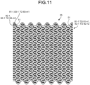
- FIG. 11 is a plan view illustrating the plurality of odd-numbered flow path walls 81-1 to 81-n1 and the plurality of even-numbered flow path walls 82-1 to 82-n2 formed in the bulkhead heat exchanger of the third example.
- the plurality of odd-numbered flow path walls 81-1 to 81-n1 and the plurality of even-numbered flow path walls 82-1 to 82-n2 are alternately arranged in the span direction 44.
- the odd-numbered flow path wall 71-1 described above in one odd-numbered flow path wall 81-1 of the plurality of odd-numbered flow path walls 81-1 to 81-n1, a plurality of odd-numbered notches 73 which does not have the flow path wall are formed, and thus, one odd-numbered flow path wall 81-1 is divided into a plurality of odd-numbered flow path wall elements 83-1 to 83-m1.
- one even-numbered flow path wall 82-1 of the plurality of even-numbered flow path walls 82-1 to 82-n2 a plurality of even-numbered notches 75 which do not have the flow path wall are formed, and thus, one even-numbered flow path wall 82-1 is divided into a plurality of even-numbered flow path wall elements 84-1 to 84-m2.
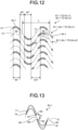
- FIG. 12 is an explanatory view schematically illustrating the plurality of odd-numbered flow path walls 81-1 to 81-n1 and the plurality of even-numbered flow path walls 82-1 to 82-n2 formed in the bulkhead heat exchanger of the third example. As illustrated in FIG.
- a portion of the odd-numbered flow path wall element 83-1 which does not have the flow path wall, that is, an in-element notch 89 (corresponding to an "in-element notch") having a shape in which a portion of the odd-numbered flow path wall element 83-1 is removed is formed, and the odd-numbered flow path wall element 83-1 is divided into two.
- FIG. 13 is a plan view illustrating the odd-numbered flow path wall element 83-1.
- the odd-numbered flow path wall element 83-1 is formed so as to conform to the sine curve 51 and includes a head 77 and a tail 78.
- the odd-numbered flow path wall element 83-1 includes a head-side edge portion 85 and a tail-side edge portion 86.
- the head-side edge portion 85 is adjacent to the in-element notch 89 and is disposed on the head 77 side from the in-element notch 89.
- the head-side edge portion 85 includes a head-side end surface 87 which faces the in-element notch 89.
- the head-side end surface 87 is formed along a plane orthogonal to the sine curve 51.
- the tail-side edge portion 86 is disposed on the tail 78 side from the in-element notch 89, and includes a tail-side end surface 88 which faces the in-element notch 89.
- the tail-side end surface 88 is formed along a plane orthogonal to the sine curve 51.
- an in-element notch 89 is formed so as to overlap an inflection point of a sine curve to which the odd-numbered flow path wall element conforms.
- FIG. 14 is a plan view illustrating the plurality of odd-numbered flow path walls 121-1 to 121-n1 and the plurality of even-numbered flow path walls 122-1 to 122-n2 formed in the bulkhead heat exchanger of the first embodiment.
- the plurality of odd-numbered flow path walls 121-1 to 121-n1 and the plurality of even-numbered flow path walls 122-1 to 122-n2 are alternately arranged in the span direction (corresponding to the "amplitude direction of the sine curve 51") 44. That is, one of the plurality of odd-numbered flow path walls 121-1 to 121-n1 and one of the plurality of even-numbered flow path walls 122-1 to 122-n2 are disposed adjacent to each other in the span direction, and one of the odd-numbered flow path wall and the even-numbered flow path wall disposed adjacent to each other in the span direction may be referred to as one flow path wall, and the other may be referred to as the other flow path wall.
- one flow path wall may be an even-numbered flow path wall, and the other flow path wall may be an odd-numbered flow path wall.
- one flow path wall may be an odd-numbered flow path wall, and the other flow path wall may be an even-numbered flow path wall.
- the odd-numbered flow path wall 121-1 in one odd-numbered flow path wall 121-1 among the plurality of odd-numbered flow path walls 121-1 to 121-n1, the plurality of odd-numbered notches 73 which do not have the flow path wall are formed in the odd-numbered flow path wall 48-1, and the odd-numbered flow path wall 121-1 is divided into a plurality of odd-numbered main flow path wall elements 123-1 to 123-m1 by the plurality of odd-numbered notches 73.
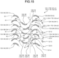
- FIG. 15 is an explanatory view schematically illustrating the plurality of odd-numbered flow path walls 121-1 to 121-n1 and the plurality of even-numbered flow path walls 122-1 to 122-n2 formed in the bulkhead heat exchanger of the first embodiment. As illustrated in FIG.
- the first odd-numbered sub flow path wall element 123-1A is formed in an upwardly convex shape
- the second odd-numbered sub flow path wall element 123-1B is formed in a downwardly convex shape.
- a portion of the odd-numbered main flow path wall element 123-2 which does not have the flow path wall that is, an odd-numbered in-element notch 89 having a shape in which a portion of the odd-numbered main flow path wall element 123-2 is removed is formed, and the odd-numbered main flow path wall element 123-2 divided into two of a first odd-numbered sub flow path wall element 123-2A and a second odd-numbered sub flow path wall element 123-2B.
- the odd-numbered in-element notch 89 is formed in the plurality of odd-numbered main flow path wall elements 123-1 to 123-m1 so as to overlap an inflection point (point at which the sine wave changes from convex upward to convex downward) at which the phase of the sine curve 51 is (2i+1) ⁇ .
- the plurality of odd-numbered main flow path wall elements 123-1 to 123-m1 are formed so as to overlap each of the maximum point and the minimum point of the sine curve 51.
- an in-element notch 90 (corresponding to the "in-element notch", and also referred to as the even-numbered in-element notch 90 in the present embodiment) having a shape in which a portion of the even-numbered main flow path wall element 124-1 is removed is formed, and one even-numbered main flow path wall element 124-1 is divided into two of a first even-numbered sub flow path wall element 124-1A and a second even-numbered sub flow path wall element 124-1B.
- FIG. 16 is an explanatory view illustrating an example of presence or absence of a sub flow path wall element for each phase range of the sine curves 51 of the odd-numbered flow path walls 121-1 to 121-n1 which are other flow path walls and the even-numbered flow path walls 122-1 to 122-n2 which are one flow path walls.
- one of the even-numbered flow path walls 122-1 to 122-n2 which are one flow path walls and one of the odd-numbered flow path walls 121-1 to 121-n1 which are the other flow path walls form two adjacent flow path walls among a plurality of sinusoidal flow path walls arranged in the span direction (amplitude direction) 44 of the sine curve 51.
- phase advanced by 60° from ⁇ 0 is ⁇ 2
- a phase advanced by 90° from ⁇ 2 is ⁇ 4
- a phase advanced by 60° from ⁇ 4 is ⁇ 5
- a phase advanced by 90° from ⁇ 5 is ⁇ 7.
- a phase advanced by 60° from ⁇ 7 becomes an inflection point ⁇ 0 after one period. This phase relationship is repeated periodically.
- the range of the phase ⁇ of ⁇ 0 to ⁇ 1 of the sine curve 51 where the even-numbered main flow path wall element 124-1 overlaps is formed to overlap a portion of the even-numbered in-element notch 90
- the range of the phase ⁇ of ⁇ 1 to ⁇ 3 of the sine curve 51 is formed to overlap the first even-numbered sub flow path wall element 124-1A
- the range of the phase ⁇ of ⁇ 3 to ⁇ 6 of the sine curve 51 is formed to overlap the even-numbered notch 75
- the range of the phase ⁇ of ⁇ 6 to ⁇ 8 of the sine curve 51 is formed to overlap the second even-numbered sub flow path wall element 124-1B
- the range of the phase ⁇ of ⁇ 8 to ⁇ 0 of the sine curve 51 is formed to overlap a portion of the even-numbered in-element notch 90.
- the plurality of even-numbered main flow path wall elements 124-1 to 124-m2 are also formed in the same manner as the plurality of odd-numbered main flow path wall elements 123-1 to 123-m1, each of the plurality of even-numbered main flow path wall elements 124-1 to 124-m2 is formed to be mirror image symmetric to the odd-numbered main flow path wall element 123-1, and the even-numbered in-element notch 90 overlapping the inflection point (point at which the sine wave changes from convex downward to convex upward) at which the phase is 2i ⁇ in the sine curve 51 to which the even-numbered main flow path wall element conforms is formed.
- flow path walls similar to the plurality of odd-numbered flow path walls 121-1 to 121-n1 and the plurality of even-numbered flow path walls 122-1 to 122-n2 are formed in the second heat exchange flow path recess 36.
- the odd-numbered flow path walls 121-1 to 121-n1 and the even-numbered flow path walls 122-1 to 122-n2 have, in addition to the shapes described above, geometrically symmetrical shapes or similar shapes with respect to the shapes described above.
- the first fluid flows through the plurality of first flow paths
- the second fluid flows through the plurality of second flow paths
- heat exchange is performed between the first fluid and the second fluid.
- the first fluid and the second fluid can be always disturbed locally, and it is possible to improve heat transfer performance in heat exchange between the first fluid and the second fluid.
- wall surfaces of the plurality of odd-numbered flow path walls 121-1 to 121-n1 and the plurality of even-numbered flow path walls 122-1 to 122-n2 conform to a sine curve.
- the plurality of odd-numbered in-element notches 89 are formed. Accordingly, compared to the bulkhead heat exchanger of the second example described above, a frictional resistance when the first fluid flows through the plurality of first flow paths is reduced, and a pressure loss is reduced. Similarly to the third example described above, in the bulkhead heat exchanger of the first embodiment, the head-side edge portion 85 and the tail-side edge portion 86 illustrated in FIG. 13 are formed.
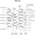
- a difference in the change in the cross-sectional area of the flow path between a case where the odd-numbered in-element notch 89 and the even-numbered in-element notch 90 are not formed and a case where the odd-numbered in-element notch and the even-numbered in-element notch are formed will be considered on the basis of FIGS. 17 and 18 .
- the odd-numbered flow path walls 71-1, 71-2, and 71-3 have the plurality of odd-numbered flow path wall elements 74-1 to 74-m1 by forming the odd-numbered notches 73, respectively.
- the even-numbered flow path walls 72-1 and 72-2 also have the plurality of even-numbered flow path wall elements 76-1 to 76-m2 by forming the even-numbered notches 75, respectively.
- the odd-numbered in-element notch 89 is not formed in each of the odd-numbered flow path walls 71-1, 71-2, and 71-3, and the even-numbered in-element notch 90 is not formed in each of the even-numbered flow path walls 72-1 and 72-2.
- the flow path width viewed in the direction orthogonal to the sine curve 51 on which each flow path wall conforms is changed, for example, between an interval W11 between the odd-numbered flow path wall element 74-1 of the adjacent odd-numbered flow path wall 71-2 and the even-numbered flow path wall element 76-1 of the even-numbered flow path wall 72-2 and an interval W12 between the odd-numbered flow path wall element 74-1 of the odd-numbered flow path wall 71-2 and the odd-numbered flow path wall element 74-1 of the odd-numbered flow path wall 71-3 adjacent via the even-numbered notch 75 formed in the even-numbered flow path wall 72-2.
- a change in the flow path width that is, a change in the cross-sectional area of the flow path causes the changes in the flow velocity and the pressure of the working fluid flowing according to Bernoulli's theorem described above, and as the change in the flow path width increases, the changes in the flow velocity and the pressure of the flowing working fluid increase.
- the change in the flow velocity and the pressure of the flowing working fluid is large, the disturbance received by the working fluid also increases, the heat transfer coefficient between the first fluid, and the first bulkhead 45 and the second bulkhead 61 is greatly improved by the contribution of the leading edge effect, and the heat transfer performance of the bulkhead heat exchanger can be improved.
- the first even-numbered sub flow path wall element 124-1A and the second even-numbered sub flow path wall element 124-1B receive a force of the flow, and generate the leading edge effect at a head portion 77 of the first even-numbered sub flow path wall element 124-1A and the edge portion 86 of the second even-numbered sub flow path wall element 124-1B.
- the flow of the working fluid forms a reduced flow in which the flow path width is reduced between the first even-numbered sub flow path wall element 124-1A of the even-numbered flow path wall 122-1, and the first odd-numbered sub flow path wall element 123-1A of the odd-numbered flow path wall 121-1 and the first odd-numbered sub flow path wall element 123-1A of the odd-numbered flow path wall 121-2 on both sides of the first even-numbered sub flow path wall element 124-1A, forms an expanded flow in which the flow path width increases after passing through the first even-numbered sub flow path wall element 124-1A of the even-numbered flow path wall 122-1, and flows between the second odd-numbered sub flow path wall element 123-1B of the odd-numbered flow path wall 121-1 and the second odd-numbered sub flow path wall element 123-1B of the odd-numbered flow path wall 121-2 to form a reduced flow in which the flow path width is reduced by the second even-numbered sub flow path wall element 124-1B of the even-numbered flow path wall 122-1.
- the flow path width is
- a separated flow is generated at an edge point Y1 of the second odd-numbered sub flow path wall element 123-1B of the odd-numbered flow path wall 121-1 and an edge point Y2 of the first odd-numbered sub flow path wall element 123-1A of the odd-numbered flow path wall 121-2.
- a separated flow is generated at an edge point Y3 of the second even-numbered sub flow path wall element 124-1B of the even-numbered flow path wall 122-1 and an edge point Y4 of the second odd-numbered sub flow path wall element 123-1B of the odd-numbered flow path wall 121-2 due to a force F2 generated on the same principle as the force F1.
- the separated flow is generated at the edge point of the flow path wall element, and thus, the leading edge effect can be further obtained, which can greatly contribute to the promotion of heat transfer.
- the plurality of odd-numbered flow path wall elements 83-1 to 83-m1 of the bulkhead heat exchanger of the third example described above are replaced with a plurality of other odd-numbered flow path wall elements, and the plurality of even-numbered flow path wall elements 84-1 to 84-m2 are replaced with a plurality of other even-numbered flow path wall elements.
- FIG. 20 is a plan view illustrating one odd-numbered flow path wall element 91 and one odd-numbered main flow path wall element 91 of the plurality of odd-numbered flow path wall elements formed in the bulkhead heat exchanger of the second embodiment. As illustrated in FIG.
- the odd-numbered flow path wall element 91 is formed similarly to the above-described odd-numbered flow path wall element 83-1 and includes a head 77 and a tail 78. Moreover, the odd-numbered flow path wall element 91 includes a head-side edge portion 85 and a tail-side edge portion 86. Moreover, the odd-numbered main flow path wall element 91 is formed similarly to the above-described odd-numbered main flow path wall element 123-1 and includes a head 77 and a tail 78. Moreover, the odd-numbered main flow path wall element 91 includes a head-side edge portion 85 and a tail-side edge portion 86.
- the in-element notch 89 which is a distance between the head-side edge portion 85 and the tail-side edge portion 86.
- other flow path wall elements different from the odd-numbered flow path wall elements 91 and the odd-numbered main flow path wall elements 91 also include intermediate flow path wall elements 92, similarly to the odd-numbered flow path wall element 91 and the odd-numbered main flow path wall element 91. That is, the intermediate flow path wall element 92 is periodically formed at each period T in each of the plurality of flow path walls of the bulkhead heat exchanger of the third example and first embodiment described above.
- the intermediate flow path wall element 92 is formed and the length D of the in-element notch 89 increases. Accordingly, compared to the bulkhead heat exchangers of the third example and first embodiment, it is possible to reduce a frictional resistance caused by the flow path wall when the fluid flows through the flow path.
- the intermediate flow path wall element 92 guides the flow of the fluid flowing along the odd-numbered flow path wall element 91 and the odd-numbered main flow path wall element 91, and increases the length D of the in-element notch 89.
- the intermediate flow path wall element 92 is disposed so as to overlap the inflection point of the sine curve 51 to which the odd-numbered flow path wall element 91 and the odd-numbered main flow path wall element 91 conform.
- the intermediate flow path wall element 92 may be disposed so as not to overlap the inflection point. Even when the intermediate flow path wall element 92 is formed so as not to overlap with the inflection point, since the intermediate flow path wall element 92 is disposed in the region where the in-element notch 89 is formed, it is possible to obtain the same action and effect as described above.
- the intermediate flow path wall element 92 is formed in the columnar shape. However, the intermediate flow path wall element 92 may be formed in a shape other than the columnar shape. Even when the intermediate flow path wall element 92 is formed in a shape other than the columnar shape, the same actions and effects as described above can be obtained.
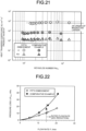
- FIG. 21 is a graph illustrating a heat transfer coefficient K and a product KA of the heat transfer coefficient K and a heat transfer area in the bulkhead heat exchanger of the second embodiment and a bulkhead heat exchanger of a comparative example.
- the bulkhead heat exchanger of the comparative example is a so-called plate heat exchanger.
- the graph of FIG. 21 illustrates that the product KA in the bulkhead heat exchanger of the second embodiment and the product KA in the bulkhead heat exchanger of the comparative example are approximately the same as each other, and illustrates that the bulkhead heat exchanger of the comparative example has a heat exchange capacity equivalent to that of the bulkhead heat exchanger of the second embodiment.
- the heat transfer coefficient K of the bulkhead heat exchanger of the second embodiment is approximately 10 times the heat transfer coefficient K of the bulkhead heat exchanger of the comparative example, and illustrates that the heat transfer coefficient K of the bulkhead heat exchanger of the second embodiment is larger than the heat transfer coefficient K of the bulkhead heat exchanger of the comparative example. That is, the graph of FIG. 21 illustrates that the bulkhead heat exchanger of the second embodiment has high heat transfer performance for heat exchange compared to the plate heat exchanger having the heat exchange capacity equivalent to that of the bulkhead heat exchanger of the second embodiment.
- FIG. 22 is a graph illustrating a pressure loss of the bulkhead heat exchanger of the second embodiment and a pressure loss of the bulkhead heat exchanger of the comparative example.
- the graph of FIG. 22 illustrates that the pressure loss of the bulkhead heat exchanger of the second embodiment is 44% of the pressure loss of the bulkhead heat exchanger of the comparative example, and illustrates that the pressure loss of the bulkhead heat exchanger of the second embodiment can be reduced compared to the bulkhead heat exchanger of the comparative example.
- a hydraulic diameter of the flow path of the bulkhead heat exchanger of the second embodiment is smaller than 1.0 mm and is smaller than a hydraulic diameter of the flow path of the bulkhead heat exchanger of the comparative example.
- the first flow path walls 48-1 to 48-n are used as the representative) of the bulkhead heat exchanger of the embodiment
- the first side flow path wall surface 52 and the second side flow path wall surface 53 are formed along two sine curves obtained by offsetting the sine curve 51 where the plurality of first flow path walls 48-1 to 48-n overlap, but may be formed along two sine curves obtained by changing the amplitude of the sine curve 51.
- FIG. 23 is a plan view illustrating a portion of one flow path wall included in a bulkhead heat exchanger of a modification example.
- a flow path wall 101 is formed so as to conform to the sine curve 51 and is formed of a plurality of first side portions 103 and a plurality of second side portions 104.
- the plurality of first side portions 103 overlap a portion of the sine curve 51 which is convex upward.
- the plurality of second side portions 104 overlap a portion of the sine curve 51 which is convex downward.
- the plurality of first side portions 103 include a first convex flow path wall surface 105 and a first concave flow path wall surface 106.
- the plurality of second side portions 104 include a second convex flow path wall surface 107 and a second concave flow path wall surface 108.
- the second convex flow path wall surface 107 is formed on the second sidewall 47 side of the plurality of second side portions 104.
- the second concave flow path wall surface 108 is formed on the first sidewall 46 side of the plurality of second side portions 104.
- the first concave flow path wall surface 106 and the second concave flow path wall surface 108 are formed so as to conform to one sine curve 112 (corresponding to a "second sine curve”).
- the sine curve 112 is formed so that a period of the sine curve 112 is equal to the period of the sine curve 51.
- the sine curve 112 is formed so that an amplitude of the sine curve 112 is smaller than the amplitude of the sine curve 51.
- the sine curve 112 is formed so that the amplitude of the sine curve 112 is equal to positive number times less than 1 (for example, 0.8 times) the amplitude A of the sine curve 51.
- the sine curve 112 is formed so that the period of the sine curve 112 is equal to the period of the sine curve 111, and the amplitude of the sine curve 112 is smaller than the amplitude of the sine curve 111. Moreover, the sine curve 112 is formed so that a plurality of inflection points of the sine curve 112 overlap the plurality of inflection points of the sine curve 51 and that the sine curve 112 intersects the sine curve 51 at the plurality of inflection points of the sine curve 112.
- the sine curve 112 is formed so that the plurality of inflection points of the sine curve 112 overlap the plurality of inflection points of the sine curve 111 and that the sine curve 112 intersects the sine curve 111 at the plurality of inflection points of the sine curve 112.
- the bulkhead heat exchanger even when the plurality of first flow path walls are replaced with the flow path walls 101, it is possible to change the flow direction of the first fluid in the plurality of first flow paths. Moreover, in the bulkhead heat exchanger, cross-sectional areas of the plurality of first flow paths are changed depending on the positions, and thus, it is possible to change the speed of the first fluid flowing through the plurality of first flow paths. In addition, in the bulkhead heat exchanger, even when the plurality of second flow path walls are replaced with the flow path walls 101, it is possible to change the flow direction of the second fluid in the plurality of second flow paths.
- the thinness of the temperature boundary layer is physically secured by the restriction of the flow path wall height, and thus, the change in the flow of the working fluid, the leading edge effect due to the edge structure, and the turbulence effect due to the generation of the vortex are obtained, the thinning of the temperature boundary layer, the occurrence of many leading edge effects, and the disturbance to the flow can be fully utilized for the means capable of promoting heat transfer, and it is possible to obtain a heat transfer promotion effect of a fine structure that has never been described before.
- one odd-numbered in-element notch (in-element notch) 89 is formed in each of the plurality of odd-numbered flow path wall elements 83-1 to 83-m1 and the plurality of odd-numbered main flow path wall elements 123-1 to 123-m1, and one even-numbered in-element notch (in-element notch) 90 is formed in each of the plurality of even-numbered flow path wall elements 84-1 to 84-m2 and the plurality of even-numbered main flow path wall elements 124-1 to 124-m2.
- the number of odd-numbered in-element notches (in-element notches) 89 formed may be two or more and the number of the even-numbered in-element notches (in-element notches) 90 formed may be two or more.
Landscapes
- Engineering & Computer Science (AREA)
- Physics & Mathematics (AREA)
- Thermal Sciences (AREA)
- Mechanical Engineering (AREA)
- General Engineering & Computer Science (AREA)
- Fluid Mechanics (AREA)
- Heat-Exchange Devices With Radiators And Conduit Assemblies (AREA)
Claims (9)
- Échangeur de chaleur à cloison (1) comprenant :une première cloison (45) ;une seconde cloison (61) ; etune pluralité de parois de trajet d'écoulement (48-1 à 48-n) qui divisent un espace (67) formé entre la première cloison (45) et la seconde cloison (61) en une pluralité de premiers trajets d'écoulement (65),dans lequel la première cloison (45) et la seconde cloison (61) séparent la pluralité de premiers trajets d'écoulement (65) d'un second trajet d'écoulement (66) à travers s'écoule un second fluide différent d'un premier fluide s'écoulant à travers la pluralité de premiers trajets d'écoulement (65),une pluralité de surfaces de paroi (41, 42) est formée sur la pluralité de parois de trajet d'écoulement (48-1 à 48-n),chacune de la pluralité de surfaces de paroi (41, 42) se conforme à une courbe sinusoïdale (51) à des différentes positions, etdeux parois de trajet d'écoulement adjacentes parmi une pluralité de parois de trajet d'écoulement sinusoïdales disposées dans une direction d'amplitude de la courbe sinusoïdale sont des parois de trajet d'écoulement sinusoïdales ayant une plage de phase de θ0 (= 0°) < θ1 < θ2 < 90° < θ3 < θ4 < 180° < θ5 < θ6 < 270° < θ7 < θ8 < θ0 (= 360°) comme une période lorsqu'une phase chevauchant un point d'inflexion d'une courbe sinusoïdale d'une paroi de trajet d'écoulement est θ0 (= 0°),caractérisé en ce quedans l'une des parois de trajet d'écoulement (122-1 à 122-n2), un élément principal de paroi de trajet d'écoulement (124-1 à 124-m2) est formé dans une partie chevauchant une plage d'une phase θ de θ1 ≤ θ < θ3 et θ6 ≤ θ < θ8 en formant une partie (75, 90) qui n'a pas la paroi de trajet d'écoulement dans une partie chevauchant une plage d'une phase θ de θ0 ≤ θ < θ1, θ3 ≤ θ < θ6 et θ8 ≤ θ < θ0, etdans l'autre des parois de trajet d'écoulement (121-1 à 121-n1), un élément principal de paroi de trajet d'écoulement (123-1 à 123-m1) est formé dans une partie chevauchant une plage d'une phase θ de θ2 ≤ θ < θ4 et θ5 ≤ θ < θ7 en formant une partie (73, 89) qui n'a pas la paroi de trajet d'écoulement dans une partie chevauchant une plage d'une phase θ de θ0 ≤ θ < θ2, θ4 ≤ θ < θ5 et θ7 ≤ θ < θ0.
- Échangeur de chaleur à cloison (1) selon la revendication 1,dans lequel l'élément principal de paroi de trajet d'écoulement (124-1 à 124-m2) de ladite une paroi de trajet d'écoulement (122-1 à 122-n2) comprendun premier élément de paroi de sous-trajet d'écoulement (124-1A à 124-m2A) qui est formé dans une partie chevauchant la plage de la phase θ de θ1 ≤ θ < θ3 et un second élément de paroi de sous-trajet d'écoulement (124-1B à 124-m2B) qui est formé dans une partie chevauchant la plage de la phase θ de θ6 ≤ θ < θ8, etl'élément principal de paroi de trajet d'écoulement (123-1 à 123-m1) de l'autre paroi de trajet d'écoulement (121-1 à 121-n1) comprendun premier élément de paroi de sous-trajet d'écoulement (123-1A à 123-m1A) qui est formé dans une partie chevauchant la plage de la phase θ de θ2 ≤ θ < θ4 et un second élément de paroi de sous-trajet d'écoulement (123-1B à 123-m1B) qui est formé dans une partie chevauchant la plage de la phase θ de θ5 ≤ θ < θ7.
- Échangeur de chaleur à cloison (1) selon la revendication 2,dans lequel la partie (75, 90) de ladite une paroi de trajet d'écoulement (122-1 à 122-n2) qui n'a pas de paroi de trajet d'écoulement comprendune encoche (75) qui n'a pas de paroi de trajet d'écoulement formée dans la partie chevauchant la plage de la phase θ de θ3 ≤ θ < θ6, et une encoche dans l'élément (90) qui n'a pas la paroi de trajet d'écoulement formée dans la partie chevauchant la plage de la phase θ de θ0 ≤ θ < θ1 et θ8 ≤ θ < θ0, etla partie (73, 89) de l'autre paroi de trajet d'écoulement (121-1 à 121-n1) qui n'a pas la paroi de trajet d'écoulement comprendune encoche (73) qui n'a pas la paroi de trajet d'écoulement formée dans la partie chevauchant la plage de la phase θ de θ4 ≤ θ < θ5, et une encoche dans l'élément (89) qui n'a pas la paroi de trajet d'écoulement formée dans la partie chevauchant la plage de la phase θ de θ0 ≤ θ < θ2 et θ7 ≤ θ < θ0.
- Échangeur de chaleur à cloison (1) comprenant :une première cloison (45) ;une seconde cloison (61) ; etune pluralité de parois de trajet d'écoulement (48-1 à 48-n) qui divisent un espace (67) formé entre la première cloison (45) et la seconde cloison (61) en une pluralité de premiers trajets d'écoulement (65),dans lequel la première cloison (45) et la seconde cloison (61) séparent la pluralité de premiers trajets d'écoulement (65) d'un second trajet d'écoulement (66) à travers s'écoule un second fluide différent d'un premier fluide s'écoulant à travers la pluralité de premiers trajets d'écoulement (65),une pluralité de surfaces de paroi (41, 42) est formée sur la pluralité de parois de trajet d'écoulement (48-1 à 48-n),chacune de la pluralité de surfaces de paroi (41, 42) se conforme à une courbe sinusoïdale (51) à des différentes positions, etdeux parois de trajet d'écoulement adjacentes parmi une pluralité de parois de trajet d'écoulement sinusoïdales disposées dans une direction d'amplitude de la courbe sinusoïdale sont des parois de trajet d'écoulement sinusoïdales ayant une plage de phase de θ0 (= 0°) < θ1 < θ2 < 90° < θ3 < θ4 < 180° < θ5 < θ6 < 270° < θ7 < θ8 < θ0 (= 360°) comme une période lorsqu'une phase chevauchant un point d'inflexion d'une courbe sinusoïdale d'une paroi de trajet d'écoulement est θ0 (= 0°),caractérisé en ce quedans l'une des parois de trajet d'écoulement, un premier élément de paroi de sous-trajet d'écoulement est formé dans une partie chevauchant une plage d'une phase θ de θ1 ≤ θ < θ3 et un second élément de paroi de sous-trajet d'écoulement est formé dans une partie chevauchant une plage d'une phase θ de θ6 ≤ θ < 8 en formant une encoche qui n'a pas la paroi de trajet d'écoulement dans une partie chevauchant une plage d'une phase θ de θ3 ≤ θ < θ6 et une encoche dans l'élément qui n'a pas la paroi de trajet d'écoulement formée dans une partie chevauchant une plage d'une phase θ de θ0 ≤ θ < θ1 et θ8 ≤ θ < θ0 sauf pour un élément de paroi de trajet d'écoulement intermédiaire qui est disposé dans l'encoche dans l'élément, etdans l'autre des parois de trajet d'écoulement, un premier élément de paroi de sous-trajet d'écoulement est formé dans une partie chevauchant une plage d'une phase θ de θ2 ≤ θ < θ4 et un second élément de paroi de sous-trajet d'écoulement est formé dans une partie chevauchant une plage d'une phase θ de θ5 ≤ θ < θ7 en formant une encoche qui n'a pas la paroi de trajet d'écoulement dans une partie chevauchant une plage d'une phase θ de θ4 ≤ θ < θ5 et une encoche dans l'élément (89) qui n'a pas la paroi de trajet d'écoulement formée dans une partie chevauchant une plage d'une phase θ de θ0 ≤ θ < θ2 et θ7 ≤ θ < θ0 sauf pour un élément de paroi de trajet d'écoulement intermédiaire (92) qui est disposé dans l'encoche dans l'élément (89).
- Échangeur de chaleur à cloison (1) selon la revendication 3 ou 4,
dans lequel chaque premier élément de paroi de sous-trajet d'écoulement (123-1A à 123-m1A, 124-1A à 124-m2A) et seconde élément de paroi de sous-trajet d'écoulement (123-1B à 123-m1B, 124-1B à 124-m2B) est formé de manière à ce qu'une largeur de celui-ci soit progressivement réduite à partir d'une partie intermédiaire de l'élément de paroi de sous-trajet d'écoulement vers une extrémité adjacente à l'encoche (73, 75). - Échangeur de chaleur à cloison (1) selon l'une quelconque des revendications 1 à 5,dans lequel chacune de la pluralité de parois de trajet d'écoulement (48-1 à 48-n) comprendune première surface de paroi (105, 107), etune seconde surface de paroi (106, 108) formée sur un côté opposé à la première surface de paroi,les courbes sinusoïdales (51) comprennent une première courbe sinusoïdale (111) et une seconde courbe sinusoïdale (112),la première surface de paroi (105, 107) est conforme à la première courbe sinusoïdale (111) et la seconde surface de paroi (106, 108) est conforme à la seconde courbe sinusoïdale (112),une période et une amplitude de la première courbe sinusoïdale (111) sont égales à une période et une amplitude de la seconde courbe sinusoïdale (112), etla première courbe sinusoïdale (111) et la seconde courbe sinusoïdale (112) sont situées à des positions translatées d'une valeur de décalage prédéterminée dans des directions d'amplitude respectives.
- Échangeur de chaleur à cloison selon l'une quelconque des revendications 1 à 5,dans lequel chacune de la pluralité de parois de trajet d'écoulement (48-1 à 48-n) comprendune première surface de paroi (105, 107), etune seconde surface de paroi (106, 108) formée sur un côté opposé à la première surface de paroi,les courbes sinusoïdales (51) comprennent une première courbe sinusoïdale (111) et une seconde courbe sinusoïdale (112),la première surface de paroi est conforme à une première courbe sinusoïdale et la seconde surface de paroi est conforme à une seconde courbe sinusoïdale,une période de la première courbe sinusoïdale est égale à une période de la seconde courbe sinusoïdale,une amplitude de la première courbe sinusoïdale est inférieure à une amplitude de la seconde courbe sinusoïdale, etla première courbe sinusoïdale et la seconde courbe sinusoïdale se croisent en des points d'inflexion respectifs.
- Échangeur de chaleur à cloison selon l'une quelconque des revendications 1 à 7, comprenant en outreune paroi latérale (46) qui forme une surface de paroi latérale (41) à une extrémité de l'espace (67),dans lequel la surface de paroi latérale (41) se conforme à une autre courbe sinusoïdale ayant la même période que celle des courbes sinusoïdales (51).
- Échangeur de chaleur à cloison (1) selon l'une quelconque des revendications 1 à 8,
dans lequel une valeur obtenue en divisant une valeur minimale d'un intervalle entre la pluralité de parois de trajet d'écoulement (48-1 à 48-n) par un intervalle entre la première cloison (45) et la seconde cloison (46) est supérieure à 2,5 et inférieure à 6.
Applications Claiming Priority (2)
| Application Number | Priority Date | Filing Date | Title |
|---|---|---|---|
| JP2019139140A JP6881516B2 (ja) | 2019-07-29 | 2019-07-29 | 隔壁式熱交換器 |
| PCT/JP2020/025286 WO2021019993A1 (fr) | 2019-07-29 | 2020-06-26 | Échangeur de chaleur de type à paroi de séparation |
Publications (3)
| Publication Number | Publication Date |
|---|---|
| EP4006478A1 EP4006478A1 (fr) | 2022-06-01 |
| EP4006478A4 EP4006478A4 (fr) | 2023-08-09 |
| EP4006478B1 true EP4006478B1 (fr) | 2025-04-09 |
Family
ID=74228704
Family Applications (1)
| Application Number | Title | Priority Date | Filing Date |
|---|---|---|---|
| EP20846809.0A Active EP4006478B1 (fr) | 2019-07-29 | 2020-06-26 | Échangeur de chaleur de type à paroi de séparation |
Country Status (6)
| Country | Link |
|---|---|
| US (1) | US11994349B2 (fr) |
| EP (1) | EP4006478B1 (fr) |
| JP (1) | JP6881516B2 (fr) |
| CN (1) | CN114174754B (fr) |
| AU (1) | AU2020323285B2 (fr) |
| WO (1) | WO2021019993A1 (fr) |
Families Citing this family (2)
| Publication number | Priority date | Publication date | Assignee | Title |
|---|---|---|---|---|
| US20240318920A1 (en) * | 2021-06-30 | 2024-09-26 | Zhejiang Ascenrise Heat Pump Co., Ltd. | Heat exchanger and manufacturing method therefor |
| JP7722494B1 (ja) * | 2024-03-11 | 2025-08-13 | 株式会社富士通ゼネラル | 熱交換器 |
Family Cites Families (17)
| Publication number | Priority date | Publication date | Assignee | Title |
|---|---|---|---|---|
| JP2006125767A (ja) * | 2004-10-29 | 2006-05-18 | Tokyo Institute Of Technology | 熱交換器 |
| JP2006170549A (ja) * | 2004-12-17 | 2006-06-29 | Yasuyoshi Kato | 熱交換器 |
| JP4675283B2 (ja) * | 2006-06-14 | 2011-04-20 | トヨタ自動車株式会社 | ヒートシンクおよび冷却器 |
| JP2008128574A (ja) * | 2006-11-21 | 2008-06-05 | Toshiba Corp | 熱交換器 |
| KR20080060933A (ko) * | 2006-12-27 | 2008-07-02 | 엘지전자 주식회사 | 환기 장치의 열교환기 |
| JP4849041B2 (ja) * | 2007-09-11 | 2011-12-28 | 株式会社富士通ゼネラル | 熱交換器 |
| US8474516B2 (en) * | 2008-08-08 | 2013-07-02 | Mikros Manufacturing, Inc. | Heat exchanger having winding micro-channels |
| JP5487423B2 (ja) * | 2009-07-14 | 2014-05-07 | 株式会社神戸製鋼所 | 熱交換器 |
| DE102010030781A1 (de) | 2010-06-30 | 2012-01-05 | Sgl Carbon Se | Wärmeübertragerplatte, damit versehener Plattenwärmeübertrager und Verfahren zum Herstellen eines Plattenwärmeübertragers |
| CN202361862U (zh) | 2011-08-30 | 2012-08-01 | 南京航空航天大学 | 高低交错波纹的板式换热器板片 |
| US20150122467A1 (en) * | 2012-05-29 | 2015-05-07 | Hangzhou Shenshi Energy Conservation Technology Co., Ltd. | Micro-channel structure for heat exchanger and integrated type micro-channel heat exchanger |
| FR3024224B1 (fr) | 2014-07-25 | 2018-12-07 | Airbus Helicopters | Echangeur thermique a plaques avec renforts structurels pour turbomoteur |
| JP6536205B2 (ja) | 2015-06-19 | 2019-07-03 | 大日本印刷株式会社 | シート状ロウ材、熱交換器の製造方法および熱交換器 |
| JP2017106648A (ja) * | 2015-12-07 | 2017-06-15 | 大日本印刷株式会社 | 熱交換器 |
| CN105547019B (zh) | 2015-12-15 | 2017-10-20 | 西安交通大学 | 一种非均匀分布肋片的高温高压板式换热器 |
| JP6663899B2 (ja) | 2017-11-29 | 2020-03-13 | 本田技研工業株式会社 | 冷却装置 |
| JP6642603B2 (ja) | 2018-02-28 | 2020-02-05 | 株式会社富士通ゼネラル | 隔壁式熱交換器 |
-
2019
- 2019-07-29 JP JP2019139140A patent/JP6881516B2/ja active Active
-
2020
- 2020-06-26 AU AU2020323285A patent/AU2020323285B2/en active Active
- 2020-06-26 US US17/627,011 patent/US11994349B2/en active Active
- 2020-06-26 WO PCT/JP2020/025286 patent/WO2021019993A1/fr not_active Ceased
- 2020-06-26 EP EP20846809.0A patent/EP4006478B1/fr active Active
- 2020-06-26 CN CN202080052132.2A patent/CN114174754B/zh active Active
Also Published As
| Publication number | Publication date |
|---|---|
| WO2021019993A1 (fr) | 2021-02-04 |
| JP6881516B2 (ja) | 2021-06-02 |
| AU2020323285B2 (en) | 2023-06-22 |
| JP2021021549A (ja) | 2021-02-18 |
| CN114174754B (zh) | 2024-11-19 |
| US11994349B2 (en) | 2024-05-28 |
| CN114174754A (zh) | 2022-03-11 |
| AU2020323285A1 (en) | 2022-03-03 |
| US20220260325A1 (en) | 2022-08-18 |
| EP4006478A1 (fr) | 2022-06-01 |
| EP4006478A4 (fr) | 2023-08-09 |
Similar Documents
| Publication | Publication Date | Title |
|---|---|---|
| EP3760961B1 (fr) | Échangeur thermique à cloisons | |
| JP5487423B2 (ja) | 熱交換器 | |
| EP4006478B1 (fr) | Échangeur de chaleur de type à paroi de séparation | |
| JP7480487B2 (ja) | 熱交換器 | |
| US10578367B2 (en) | Plate heat exchanger with alternating symmetrical and asymmetrical plates | |
| WO2018047469A1 (fr) | Échangeur thermique | |
| SE528275C2 (sv) | Värmeöverföringsplatta med styrorgan samt värmeväxlare som innefattar sådana plattor | |
| JP7552427B2 (ja) | 熱交換器 | |
| JP5814163B2 (ja) | 冷却器 | |
| JP6187038B2 (ja) | 熱交換器及び熱交換器の製造方法 | |
| US20250275091A1 (en) | Cooling block for cooling a heat-generating electronic component | |
| JP6525248B2 (ja) | 熱交換器および熱交換器用プレートユニット | |
| JP2023176623A (ja) | 熱交換器 | |
| JP4983664B2 (ja) | 冷却装置 | |
| JP5727327B2 (ja) | 熱交換器 | |
| JP2009224652A (ja) | 冷却装置 | |
| JP2016223719A (ja) | 熱交換器及び熱交換器用オフセットフィン | |
| WO2020100687A1 (fr) | Échangeur de chaleur | |
| JP2015045455A (ja) | 熱交換器 | |
| JP2018096584A (ja) | 熱交換器 |
Legal Events
| Date | Code | Title | Description |
|---|---|---|---|
| STAA | Information on the status of an ep patent application or granted ep patent |
Free format text: STATUS: THE INTERNATIONAL PUBLICATION HAS BEEN MADE |
|
| PUAI | Public reference made under article 153(3) epc to a published international application that has entered the european phase |
Free format text: ORIGINAL CODE: 0009012 |
|
| STAA | Information on the status of an ep patent application or granted ep patent |
Free format text: STATUS: REQUEST FOR EXAMINATION WAS MADE |
|
| 17P | Request for examination filed |
Effective date: 20220121 |
|
| AK | Designated contracting states |
Kind code of ref document: A1 Designated state(s): AL AT BE BG CH CY CZ DE DK EE ES FI FR GB GR HR HU IE IS IT LI LT LU LV MC MK MT NL NO PL PT RO RS SE SI SK SM TR |
|
| DAV | Request for validation of the european patent (deleted) | ||
| DAX | Request for extension of the european patent (deleted) | ||
| A4 | Supplementary search report drawn up and despatched |
Effective date: 20230712 |
|
| RIC1 | Information provided on ipc code assigned before grant |
Ipc: F28D 9/00 20060101ALI20230706BHEP Ipc: F28F 3/02 20060101ALI20230706BHEP Ipc: F28D 9/02 20060101AFI20230706BHEP |
|
| GRAP | Despatch of communication of intention to grant a patent |
Free format text: ORIGINAL CODE: EPIDOSNIGR1 |
|
| STAA | Information on the status of an ep patent application or granted ep patent |
Free format text: STATUS: GRANT OF PATENT IS INTENDED |
|
| INTG | Intention to grant announced |
Effective date: 20241105 |
|
| GRAS | Grant fee paid |
Free format text: ORIGINAL CODE: EPIDOSNIGR3 |
|
| GRAA | (expected) grant |
Free format text: ORIGINAL CODE: 0009210 |
|
| STAA | Information on the status of an ep patent application or granted ep patent |
Free format text: STATUS: THE PATENT HAS BEEN GRANTED |
|
| AK | Designated contracting states |
Kind code of ref document: B1 Designated state(s): AL AT BE BG CH CY CZ DE DK EE ES FI FR GB GR HR HU IE IS IT LI LT LU LV MC MK MT NL NO PL PT RO RS SE SI SK SM TR |
|
| REG | Reference to a national code |
Ref country code: GB Ref legal event code: FG4D |
|
| REG | Reference to a national code |
Ref country code: CH Ref legal event code: EP |
|
| REG | Reference to a national code |
Ref country code: DE Ref legal event code: R096 Ref document number: 602020049261 Country of ref document: DE |
|
| REG | Reference to a national code |
Ref country code: IE Ref legal event code: FG4D |
|
| PGFP | Annual fee paid to national office [announced via postgrant information from national office to epo] |
Ref country code: DE Payment date: 20250626 Year of fee payment: 6 |
|
| PGFP | Annual fee paid to national office [announced via postgrant information from national office to epo] |
Ref country code: GB Payment date: 20250620 Year of fee payment: 6 |
|
| PGFP | Annual fee paid to national office [announced via postgrant information from national office to epo] |
Ref country code: FR Payment date: 20250618 Year of fee payment: 6 |
|
| REG | Reference to a national code |
Ref country code: NL Ref legal event code: MP Effective date: 20250409 |
|
| PG25 | Lapsed in a contracting state [announced via postgrant information from national office to epo] |
Ref country code: NL Free format text: LAPSE BECAUSE OF FAILURE TO SUBMIT A TRANSLATION OF THE DESCRIPTION OR TO PAY THE FEE WITHIN THE PRESCRIBED TIME-LIMIT Effective date: 20250409 |
|
| REG | Reference to a national code |
Ref country code: AT Ref legal event code: MK05 Ref document number: 1783847 Country of ref document: AT Kind code of ref document: T Effective date: 20250409 |
|
| PG25 | Lapsed in a contracting state [announced via postgrant information from national office to epo] |
Ref country code: FI Free format text: LAPSE BECAUSE OF FAILURE TO SUBMIT A TRANSLATION OF THE DESCRIPTION OR TO PAY THE FEE WITHIN THE PRESCRIBED TIME-LIMIT Effective date: 20250409 Ref country code: ES Free format text: LAPSE BECAUSE OF FAILURE TO SUBMIT A TRANSLATION OF THE DESCRIPTION OR TO PAY THE FEE WITHIN THE PRESCRIBED TIME-LIMIT Effective date: 20250409 Ref country code: PT Free format text: LAPSE BECAUSE OF FAILURE TO SUBMIT A TRANSLATION OF THE DESCRIPTION OR TO PAY THE FEE WITHIN THE PRESCRIBED TIME-LIMIT Effective date: 20250811 |
|
| REG | Reference to a national code |
Ref country code: LT Ref legal event code: MG9D |
|
| PG25 | Lapsed in a contracting state [announced via postgrant information from national office to epo] |
Ref country code: GR Free format text: LAPSE BECAUSE OF FAILURE TO SUBMIT A TRANSLATION OF THE DESCRIPTION OR TO PAY THE FEE WITHIN THE PRESCRIBED TIME-LIMIT Effective date: 20250710 Ref country code: NO Free format text: LAPSE BECAUSE OF FAILURE TO SUBMIT A TRANSLATION OF THE DESCRIPTION OR TO PAY THE FEE WITHIN THE PRESCRIBED TIME-LIMIT Effective date: 20250709 |
|
| PG25 | Lapsed in a contracting state [announced via postgrant information from national office to epo] |
Ref country code: PL Free format text: LAPSE BECAUSE OF FAILURE TO SUBMIT A TRANSLATION OF THE DESCRIPTION OR TO PAY THE FEE WITHIN THE PRESCRIBED TIME-LIMIT Effective date: 20250409 |
|
| PG25 | Lapsed in a contracting state [announced via postgrant information from national office to epo] |
Ref country code: BG Free format text: LAPSE BECAUSE OF FAILURE TO SUBMIT A TRANSLATION OF THE DESCRIPTION OR TO PAY THE FEE WITHIN THE PRESCRIBED TIME-LIMIT Effective date: 20250409 |
|
| PG25 | Lapsed in a contracting state [announced via postgrant information from national office to epo] |
Ref country code: HR Free format text: LAPSE BECAUSE OF FAILURE TO SUBMIT A TRANSLATION OF THE DESCRIPTION OR TO PAY THE FEE WITHIN THE PRESCRIBED TIME-LIMIT Effective date: 20250409 |
|
| PG25 | Lapsed in a contracting state [announced via postgrant information from national office to epo] |
Ref country code: AT Free format text: LAPSE BECAUSE OF FAILURE TO SUBMIT A TRANSLATION OF THE DESCRIPTION OR TO PAY THE FEE WITHIN THE PRESCRIBED TIME-LIMIT Effective date: 20250409 |
|
| PG25 | Lapsed in a contracting state [announced via postgrant information from national office to epo] |
Ref country code: RS Free format text: LAPSE BECAUSE OF FAILURE TO SUBMIT A TRANSLATION OF THE DESCRIPTION OR TO PAY THE FEE WITHIN THE PRESCRIBED TIME-LIMIT Effective date: 20250709 |
|
| PG25 | Lapsed in a contracting state [announced via postgrant information from national office to epo] |
Ref country code: IS Free format text: LAPSE BECAUSE OF FAILURE TO SUBMIT A TRANSLATION OF THE DESCRIPTION OR TO PAY THE FEE WITHIN THE PRESCRIBED TIME-LIMIT Effective date: 20250809 |
|
| PG25 | Lapsed in a contracting state [announced via postgrant information from national office to epo] |
Ref country code: LV Free format text: LAPSE BECAUSE OF FAILURE TO SUBMIT A TRANSLATION OF THE DESCRIPTION OR TO PAY THE FEE WITHIN THE PRESCRIBED TIME-LIMIT Effective date: 20250409 |
|
| REG | Reference to a national code |
Ref country code: DE Ref legal event code: R097 Ref document number: 602020049261 Country of ref document: DE |
|
| PG25 | Lapsed in a contracting state [announced via postgrant information from national office to epo] |
Ref country code: DK Free format text: LAPSE BECAUSE OF FAILURE TO SUBMIT A TRANSLATION OF THE DESCRIPTION OR TO PAY THE FEE WITHIN THE PRESCRIBED TIME-LIMIT Effective date: 20250409 Ref country code: SM Free format text: LAPSE BECAUSE OF FAILURE TO SUBMIT A TRANSLATION OF THE DESCRIPTION OR TO PAY THE FEE WITHIN THE PRESCRIBED TIME-LIMIT Effective date: 20250409 |
|
| PG25 | Lapsed in a contracting state [announced via postgrant information from national office to epo] |
Ref country code: CZ Free format text: LAPSE BECAUSE OF FAILURE TO SUBMIT A TRANSLATION OF THE DESCRIPTION OR TO PAY THE FEE WITHIN THE PRESCRIBED TIME-LIMIT Effective date: 20250409 |
|
| PG25 | Lapsed in a contracting state [announced via postgrant information from national office to epo] |
Ref country code: EE Free format text: LAPSE BECAUSE OF FAILURE TO SUBMIT A TRANSLATION OF THE DESCRIPTION OR TO PAY THE FEE WITHIN THE PRESCRIBED TIME-LIMIT Effective date: 20250409 |
|
| PG25 | Lapsed in a contracting state [announced via postgrant information from national office to epo] |
Ref country code: RO Free format text: LAPSE BECAUSE OF FAILURE TO SUBMIT A TRANSLATION OF THE DESCRIPTION OR TO PAY THE FEE WITHIN THE PRESCRIBED TIME-LIMIT Effective date: 20250409 Ref country code: SK Free format text: LAPSE BECAUSE OF FAILURE TO SUBMIT A TRANSLATION OF THE DESCRIPTION OR TO PAY THE FEE WITHIN THE PRESCRIBED TIME-LIMIT Effective date: 20250409 |
|
| REG | Reference to a national code |
Ref country code: CH Ref legal event code: H13 Free format text: ST27 STATUS EVENT CODE: U-0-0-H10-H13 (AS PROVIDED BY THE NATIONAL OFFICE) Effective date: 20260127 |
|
| PG25 | Lapsed in a contracting state [announced via postgrant information from national office to epo] |
Ref country code: IT Free format text: LAPSE BECAUSE OF FAILURE TO SUBMIT A TRANSLATION OF THE DESCRIPTION OR TO PAY THE FEE WITHIN THE PRESCRIBED TIME-LIMIT Effective date: 20250409 |
|
| PG25 | Lapsed in a contracting state [announced via postgrant information from national office to epo] |
Ref country code: MC Free format text: LAPSE BECAUSE OF FAILURE TO SUBMIT A TRANSLATION OF THE DESCRIPTION OR TO PAY THE FEE WITHIN THE PRESCRIBED TIME-LIMIT Effective date: 20250409 |
|
| PLBE | No opposition filed within time limit |
Free format text: ORIGINAL CODE: 0009261 |
|
| STAA | Information on the status of an ep patent application or granted ep patent |
Free format text: STATUS: NO OPPOSITION FILED WITHIN TIME LIMIT |
|
| PG25 | Lapsed in a contracting state [announced via postgrant information from national office to epo] |
Ref country code: LU Free format text: LAPSE BECAUSE OF NON-PAYMENT OF DUE FEES Effective date: 20250626 |
|
| REG | Reference to a national code |
Ref country code: CH Ref legal event code: L10 Free format text: ST27 STATUS EVENT CODE: U-0-0-L10-L00 (AS PROVIDED BY THE NATIONAL OFFICE) Effective date: 20260218 |
|
| REG | Reference to a national code |
Ref country code: BE Ref legal event code: MM Effective date: 20250630 |
|
| 26N | No opposition filed |
Effective date: 20260112 |
|
| PG25 | Lapsed in a contracting state [announced via postgrant information from national office to epo] |
Ref country code: IE Free format text: LAPSE BECAUSE OF NON-PAYMENT OF DUE FEES Effective date: 20250626 |
|
| PG25 | Lapsed in a contracting state [announced via postgrant information from national office to epo] |
Ref country code: BE Free format text: LAPSE BECAUSE OF NON-PAYMENT OF DUE FEES Effective date: 20250630 |
|
| PG25 | Lapsed in a contracting state [announced via postgrant information from national office to epo] |
Ref country code: CH Free format text: LAPSE BECAUSE OF NON-PAYMENT OF DUE FEES Effective date: 20250630 |