EP4006499B1 - Système de capteur de débit, méthode et utilisation de ce système pour déterminer un débit - Google Patents
Système de capteur de débit, méthode et utilisation de ce système pour déterminer un débit Download PDFInfo
- Publication number
- EP4006499B1 EP4006499B1 EP20210683.7A EP20210683A EP4006499B1 EP 4006499 B1 EP4006499 B1 EP 4006499B1 EP 20210683 A EP20210683 A EP 20210683A EP 4006499 B1 EP4006499 B1 EP 4006499B1
- Authority
- EP
- European Patent Office
- Prior art keywords
- electrodes
- pair
- fluid channel
- fluid
- sensor system
- Prior art date
- Legal status (The legal status is an assumption and is not a legal conclusion. Google has not performed a legal analysis and makes no representation as to the accuracy of the status listed.)
- Active
Links
Images


Classifications
-
- G—PHYSICS
- G01—MEASURING; TESTING
- G01F—MEASURING VOLUME, VOLUME FLOW, MASS FLOW OR LIQUID LEVEL; METERING BY VOLUME
- G01F1/00—Measuring the volume flow or mass flow of fluid or fluent solid material wherein the fluid passes through a meter in a continuous flow
- G01F1/56—Measuring the volume flow or mass flow of fluid or fluent solid material wherein the fluid passes through a meter in a continuous flow by using electric or magnetic effects
- G01F1/58—Measuring the volume flow or mass flow of fluid or fluent solid material wherein the fluid passes through a meter in a continuous flow by using electric or magnetic effects by electromagnetic flowmeters
- G01F1/584—Measuring the volume flow or mass flow of fluid or fluent solid material wherein the fluid passes through a meter in a continuous flow by using electric or magnetic effects by electromagnetic flowmeters constructions of electrodes, accessories therefor
-
- G—PHYSICS
- G01—MEASURING; TESTING
- G01F—MEASURING VOLUME, VOLUME FLOW, MASS FLOW OR LIQUID LEVEL; METERING BY VOLUME
- G01F1/00—Measuring the volume flow or mass flow of fluid or fluent solid material wherein the fluid passes through a meter in a continuous flow
- G01F1/05—Measuring the volume flow or mass flow of fluid or fluent solid material wherein the fluid passes through a meter in a continuous flow by using mechanical effects
- G01F1/34—Measuring the volume flow or mass flow of fluid or fluent solid material wherein the fluid passes through a meter in a continuous flow by using mechanical effects by measuring pressure or differential pressure
-
- G—PHYSICS
- G01—MEASURING; TESTING
- G01F—MEASURING VOLUME, VOLUME FLOW, MASS FLOW OR LIQUID LEVEL; METERING BY VOLUME
- G01F1/00—Measuring the volume flow or mass flow of fluid or fluent solid material wherein the fluid passes through a meter in a continuous flow
- G01F1/56—Measuring the volume flow or mass flow of fluid or fluent solid material wherein the fluid passes through a meter in a continuous flow by using electric or magnetic effects
-
- G—PHYSICS
- G01—MEASURING; TESTING
- G01F—MEASURING VOLUME, VOLUME FLOW, MASS FLOW OR LIQUID LEVEL; METERING BY VOLUME
- G01F1/00—Measuring the volume flow or mass flow of fluid or fluent solid material wherein the fluid passes through a meter in a continuous flow
- G01F1/56—Measuring the volume flow or mass flow of fluid or fluent solid material wherein the fluid passes through a meter in a continuous flow by using electric or magnetic effects
- G01F1/58—Measuring the volume flow or mass flow of fluid or fluent solid material wherein the fluid passes through a meter in a continuous flow by using electric or magnetic effects by electromagnetic flowmeters
-
- G—PHYSICS
- G01—MEASURING; TESTING
- G01F—MEASURING VOLUME, VOLUME FLOW, MASS FLOW OR LIQUID LEVEL; METERING BY VOLUME
- G01F1/00—Measuring the volume flow or mass flow of fluid or fluent solid material wherein the fluid passes through a meter in a continuous flow
- G01F1/05—Measuring the volume flow or mass flow of fluid or fluent solid material wherein the fluid passes through a meter in a continuous flow by using mechanical effects
- G01F1/20—Measuring the volume flow or mass flow of fluid or fluent solid material wherein the fluid passes through a meter in a continuous flow by using mechanical effects by detection of dynamic effects of the flow
- G01F1/22—Measuring the volume flow or mass flow of fluid or fluent solid material wherein the fluid passes through a meter in a continuous flow by using mechanical effects by detection of dynamic effects of the flow by variable-area meters, e.g. rotameters
-
- G—PHYSICS
- G01—MEASURING; TESTING
- G01F—MEASURING VOLUME, VOLUME FLOW, MASS FLOW OR LIQUID LEVEL; METERING BY VOLUME
- G01F1/00—Measuring the volume flow or mass flow of fluid or fluent solid material wherein the fluid passes through a meter in a continuous flow
- G01F1/05—Measuring the volume flow or mass flow of fluid or fluent solid material wherein the fluid passes through a meter in a continuous flow by using mechanical effects
- G01F1/20—Measuring the volume flow or mass flow of fluid or fluent solid material wherein the fluid passes through a meter in a continuous flow by using mechanical effects by detection of dynamic effects of the flow
- G01F1/28—Measuring the volume flow or mass flow of fluid or fluent solid material wherein the fluid passes through a meter in a continuous flow by using mechanical effects by detection of dynamic effects of the flow by drag-force, e.g. vane type or impact flowmeter
-
- G—PHYSICS
- G01—MEASURING; TESTING
- G01F—MEASURING VOLUME, VOLUME FLOW, MASS FLOW OR LIQUID LEVEL; METERING BY VOLUME
- G01F1/00—Measuring the volume flow or mass flow of fluid or fluent solid material wherein the fluid passes through a meter in a continuous flow
- G01F1/56—Measuring the volume flow or mass flow of fluid or fluent solid material wherein the fluid passes through a meter in a continuous flow by using electric or magnetic effects
- G01F1/64—Measuring the volume flow or mass flow of fluid or fluent solid material wherein the fluid passes through a meter in a continuous flow by using electric or magnetic effects by measuring electrical currents passing through the fluid flow; measuring electrical potential generated by the fluid flow, e.g. by electrochemical, contact or friction effects
Definitions
- the present invention relates to the technical field of sensing fluid movement in a flexible fluid channel, and in particular to determining a flow rate in such a fluid channel based on an expansion of the fluid channel.
- the present invention is directed to a flow rate sensor system for sensing or detecting the movement of a fluid in a fluid channel, and in more detail to a system for determining a flow rate of the fluid in the fluid channel, wherein capacitive expansion measurement is carried out in order to measure a respective capacitance change due to expansion of the fluid channel and, based thereon, determine a fluid flow rate in the fluid channel.
- the present invention is further directed to a respective method for determining the flow rate of a fluid flow within the fluid channel by means of such a system, and to the use of such a system for determining the fluid flow rate in the fluid channel.
- sensors are often rather expensive due to the required features, such as self-containment and long-term stability, since these sensors usually have to be cleaned and re-used, which is costly and time-consuming or even prohibitive, e.g. for medical applications.
- these sensors are mainly based on piezoresistive or thermal transduction mechanisms and are generally manufactured by e.g. MEMS principles. Thus, they are usually not applicable for non-contact measuring at low velocities and/or low pressure. Accordingly, there is the general need for disposable pressure or flow sensors with high sensitivity, which can be used in the course of non-contact measuring.
- US 4,484,479 A describes a gas flow metering method and system using capacitance measurement and comprising a taut elastomeric membrane, e.g. tubular in form, which expands or contracts as a function of a flow rate past it to an extent determined by Bernoulli's principle. Accordingly, US 4,484,479 A discloses a gas flow sensor system in which a distance change between a pair of electrodes and a conductive membrane is proportional to a change of pressure of a flowing gas, wherein the distance change is measured based on a capacitive principle. This solution, however, lacs a scaling element necessary for providing absolute measurement values.
- WO 2014/048911 A1 provides a pressure sensor comprising a detector configured to detect the influence of a variation of a shape of a particularly provided measurement chamber on the electrical field.
- the detector is supposed to detect the change in the electric field dependent on a change in the shape of the measurement chamber, wherein the change in the shape of the measurement chamber is effected depending on the pressure of the fluid within the measurement chamber. Accordingly, fluid pressure, and thereby indirectly fluid flow, can be measured through change of capacitance caused by deformation of the deformable measurement chamber filled with the fluid to be measured.
- a rigid-geometry fluid resistor of known geometry and a second measurement chamber are provided, in addition to the initial measurement chamber.
- the solution as presented in WO 2014/048911 A1 present several problems.
- the measurement system of WO 2014/048911 A1 is not in the position to compensate for imperfections of the fluid to be measured, which imperfections are usually present in liquids in the fork of bubbles, viscosity change, or other inhomogeneities, and, thus, can significantly falsify the desired measurement results.
- absolute flow measurements can only be done for a specific fluid for which the fluid resistor is calibrated to. Accordingly, for correct absolute measurements, at least the permittivity of a measured fluid must be known before measurement, and, even more importantly, must be maintained throughout all measurements, in order to avoid falsifying the results. Moreover, the use of a flow resistor of rigid geometry necessary for providing scaled measurement values significantly limits the allowed flow rates in order to ensure correct measuring results, since the diameter of such a resistor must be smaller than a diameter of a chamber for correct operation of the sensor system.
- the geometry of the resistor must be tuned for specific flow rates. Accordingly, the solution as suggested in WO 2014/048911 A1 , i.e. the suggested relative measurement approach with two identically working electrode pairs, either fixed or moving, can be used only under the provision that the properties of the fluid are not changing, i.e. that the fluid to be measured remains homogeneous and bubble-free.
- a sensor system for determining a flow rate of a fluid flow within a fluid channel comprises a fluid channel, for example in the form of a fluid tube, wherein the fluid channel comprises an elastic segment of the fluid channel, the elastic segment being arranged next to a rigid segment of the fluid channel.
- the system described herein comprises at least a first pair of electrodes provided at the rigid segment of the fluid channel, wherein the electrodes of the first pair of electrodes are arranged opposing each other, and wherein the first pair of electrodes is in contact with the rigid segment of the fluid channel.
- the electrodes of the first pair of electrodes occupy a fixed relative positioning with regard to each other.
- at least a second pair of electrodes is provided at the elastic segment of the fluid channel, wherein the electrodes of the second pair of electrodes are also arranged opposing each other, and wherein the second pair of electrodes is in contact with the elastic segment of the fluid channel, similarly to the first pair of electrodes at the rigid segment.
- the electrodes of the second pair of electrodes occupy a variable or moveable relative positioning with regard to each other.
- the system described herein comprises a sensor unit for detecting a capacitance of the first pair of electrodes and for detecting a capacitance of the second pair of electrodes, and a processing unit for calculating and monitoring a distance between the electrodes of the second pair of electrodes based on the detected capacitance of the first pair of electrodes and the second pair of electrodes.
- the processing unit can be adapted to determine a flow rate of the fluid flow within the fluid channel based on a difference in distance between the electrodes of the second pair of electrodes over time.
- the elastic segment of the fluid channel comprises a certain elasticity, thereby rendering the elastic segment to be at least moveable in a circumferential manner
- the rigid segment of the fluid channel lacks such elasticity, i.e. the rigid segment of the fluid channel maintains its circumferential dimension without the ability of being moveable in a circumferential manner.
- the same usually comprises an annular shape, i.e. a curved outer circumference, meaning that the electrodes can be adapted to such curved shape, resulting in that the distance between the electrodes is to be understood as equivalent effective distance between the electrodes, in view of the lack of a planar correlation.
- the flow rate sensor system as presented herein accommodates imperfections of the measured fluid, such as bubbles, viscosity change, and the like, by controlling the relative permittivity ⁇ r of the fluid present in between the first pair of electrodes placed at the rigid segment where a geometry of the system, and in particular a geometry of the fluid channel, is constant.
- a flow to be measured must be directed from the rigid segment of the fluid channel, exhibiting the first pair of electrodes, towards the elastic segment of the fluid channel, exhibiting the second pair of electrodes, in order to be able to use the first pair of electrodes as reference value.
- the thus measured relative permittivity ⁇ r can then be used as a correction parameter for measurements performed by the second pair of electrodes placed at the elastic segment.
- the unique combination of the first pair of electrodes in the form of a fixed electrode pair and the second pair of electrodes in the form of a moveable electrode pair allows for constant monitoring of the electrical permittivity by means of the fixed electrode pair.
- the moveable electrode pair provides a direct measure of the respective fluid pressure, which can be calculated into a flow rate provided that the other required system parameters are known.
- the direct measure of the fluid pressure can be obtained by means of determining the variable distance between the electrodes of the moveable electrode pair, which distance correlates to the fluid pressure and, thus, to the flow rate of the fluid to be measured.
- any pair of electrodes of the system described herein provides for the general structure of a plate-like capacitor, for which the following applies:
- C ⁇ ⁇ A / d with
- ⁇ r C 1 st ⁇ d 1 st / A 1 st ⁇ ⁇ 0 ) with
- variable relative permittivity ⁇ r of the fluid By inserting ⁇ r from equation 5 into equation 6, the variable relative permittivity ⁇ r of the fluid can be substituted, and the permittivity ⁇ 0 can be cancelled out. Thereby, the system becomes independent of the variable relative permittivity ⁇ r of the fluid and of the vacuum / absolute permittivity ⁇ 0 and depends only on the geometry of the system and the relative expansion of the elastic segment caused by pressure change in the fluid.
- variable distance between the electrodes of the second pair of electrodes i.e. of the moveable electrode pair can be determined by simply measuring the capacitances C 1st and C 2nd , and its progression over time can be recorded. Based thereon, a difference ⁇ d 2nd in distance between the electrodes of the second pair of electrodes over time reflects a change of fluid pressure within the elastic segment of the fluid channel.
- the flow rate sensor system as described herein can be regarded as independent from the relative permittivity ⁇ r of the fluid to be measured and only depends on the geometry of its structure and the relative expansion of the elastic segment of the fluid channel caused by a pressure change within the fluid. Therefore, any change of the complex permittivity ⁇ signifies a change of the fluid's properties, wherein such change in permittivity ⁇ can directly be corrected in the form of a new offset between the electrodes of the moveable electrode pair after the permittivity ⁇ has been observed in the fixed electrode pair, i.e. eliminating one another mathematically.
- the electrodes of any pair of electrodes can be implemented in the form of plate-like electrodes, which can follow an outer shape of the respective segment of the fluid channel.
- the outer shape of the fluid channel can be a circular shape, and the respective opposing electrodes can assume a respectively bent or curved shape.
- the first pair of electrodes can be in contact with an outer circumference of a wall of the fluid channel at the rigid segment.
- the second pair of electrodes can be in contact with an outer circumference of the wall of the fluid channel at the elastic segment.
- the fluid channel is a continuous channel component having connected segments with different elasticities, i.e. at least one elastic segment and at least one rigid segment
- the respective wall of the fluid channel is constituted by the single continuous wall surrounding the fluid channel.
- the first pair of electrodes and the second pair of electrodes are in contact with an outer circumference of the single continuous wall surrounding the fluid channel.
- the first pair of electrodes can be attached to the outer circumference of the wall of the fluid channel at the rigid segment.
- the second pair of electrodes can be attached to the outer circumference of the wall of the fluid channel at the elastic segment.
- attaching the electrodes to the outer circumference of the fluid channel's wall can be implemented by a mechanical connection, by means of an adhesive, or the like.
- the electrodes can be printed onto the outer circumference of the fluid channel's wall, e.g. in a stripe-shaped manner.
- the electrodes can be made of a stretchable material or in the form of a stretchable structure.
- the electrodes of the second pair of electrodes are movably arranged to one another.
- a change in diameter of the fluid channel at the elastic segment can be followed by a respective change in distance between the electrodes of the second pair of electrodes, i.e. by a movement of the electrodes towards or away from each other.
- one electrode of the second pair of electrodes provided at the elastic segment of the fluid channel can be arranged in a stationary manner, whereas the other electrode of the second pair of electrodes can be arranged ion a moveable manner, such that only the other electrode follows a change in diameter of the fluid channel at the elastic segment.
- the electrodes of the second pair of electrodes can be arranged parallel, or basically parallel, to one another.
- any movement of the electrodes towards or away from each other can occur on a common axis, such as a common central axis of the plate-like electrodes.
- the electrodes of the first pair of electrodes can also be arranged parallel to each other.
- the electrodes of the second pair of electrodes can be arranged not in parallel but in an inclined manner to one another, wherein, in case of plate-like electrodes, the same can take on a sharp angle relative to each other, for example in between 20° and 45°.
- a positional relationship between the electrodes of the first pair of electrodes can again adopt a simple stationary parallel positioning, whereas the positional relationship between the electrodes of the second pair of electrodes adopts a moveable non-parallel positioning, with variable distance and angle in between the electrodes.
- the sensor system -and in particular the respective elastic segment of the fluid channel- is designed in the form of a nozzle.
- the fluid flow to be measured can only be unidirectional, since the nozzle only works or opens in one direction.
- the flow rate sensor system as described herein can further comprise at least a third pair of electrodes provided at a further rigid segment of the fluid channel, with the electrodes of the third pair of electrodes being arranged opposing each other.
- the third pair of electrodes can exhibit identical features as the first pair of electrodes, thereby providing another fixed electrode pair.
- the third pair of electrodes can be in contact with an outer circumference of the wall of the fluid channel at the further rigid segment, wherein the third pair of electrodes can be attached to the outer circumference of the wall of the fluid channel at the further rigid segment.
- the elastic segment of the fluid channel can be arranged in between the rigid segment exhibiting the first pair of electrodes and the further rigid segment exhibiting the third pair of electrodes.
- the flow rate sensor system as described herein can further comprise at least a fourth pair of electrodes provided at a further elastic segment of the fluid channel, with the electrodes of the fourth pair of electrodes being arranged opposing each other, wherein the further rigid segment as defined above can be arranged between the elastic segment and the further elastic segment.
- the fourth pair of electrodes can exhibit identical features as the second pair of electrodes, thereby providing another moveable electrode pair.
- the fourth pair of electrodes can be in contact with an outer circumference of the wall of the fluid channel at the further elastic segment, wherein the fourth pair of electrodes can be attached to the outer circumference of the wall of the fluid channel at the further elastic segment.
- any change of permittivity ⁇ signifies a change of the fluid's properties, wherein such change in permittivity ⁇ can directly be corrected as a new offset in the moveable electrode pairs after it has been observed in the fixed electrode pairs.
- the combination of two fixed and two moveable electrode pairs allow even better constant monitoring of the electrical permittivity detected by the first fixed electrode pair.
- a method for determining a flow rate of a fluid flow within a fluid channel by means of a sensor system as described above comprises the steps of
- steps a) and b) can be switched or carried-out simultaneously without generating a false result.
- additional method steps can be carried out, also in between the above-mentioned method steps, if necessary.
- the term "detecting" as used in steps a) and b) above is to be understood in the sense of assessing or establishing a certain value for the respective capacitance, in particular by measuring the respective capacitance value of the pairs of electrodes.
- the values d 1st , A 1st and A 2nd are predetermined, i.e. constant, structural features of the system and are known to the user. Since the values C 1st and C 2nd are detected values of capacitance of the first and second pair of electrodes, the distance d 2nd between the electrodes of the second pair of electrodes can be calculated and depends on the detected values of capacitance of the first and second pair of electrodes. Accordingly, a difference ⁇ d 2nd in distance between the electrodes of the second pair of electrodes can be monitored over time and reflects a change of fluid pressure within the elastic segment of the fluid channel. Thus, the change of fluid pressure can be derived from the difference ⁇ d 2nd over time.
- a flow rate system with a fluid tube comprising a rigid segment and an elastic segment arranged next to each other is used, wherein a first pair of opposing electrodes is provided at the rigid segment, i.e. a "fixed" 1 st pair of electrodes, and a second pair of electrodes is provided at the elastic segment, i.e. a "moveable" 2 nd pair of electrodes.
- the rigid segment comprises a tubing diameter of 1 mm
- the elastic segment comprises a tubing diameter of 0.8 mm.
- the elastic segment can be fully elastic, i.e. the entire elastic segment can expand laterally, or the elastic segment can be implemented by a rigid half tube with an elastic tube-like cover.
- the elastic segment can endure an exemplary elastic deformation within a range of ⁇ 0-0.3 mm, i.e. in both expansion and contraction direction.
- fluid is introduced into the fluid tube, wherein the fluid flow and, thus, the fluid pressure is negligible.
- fluid pressure is applied to the fluid inside the fluid tube, and fluid flow is generated, resulting in an expansion of the elastic segment and, thus, enlarging the distance between the opposing electrodes of the 2 nd electrode pair.
- the expansion ratio i.e. the ratio of expansion of the elastic segment of the fluid tube
- the expansion of 75 % of the distance between the electrodes of the 2 nd pair of electrodes over a time period of 0.5 s reflects 75 % of increase of fluid pressure at the location of the 2 nd pair of electrodes at the elastic segment over a time period of 0.5 s, i.e. after 0.5 s.
- an elasticity of the elastic segment of the fluid channel can be adjusted based on the expected flow rate within the fluid channel.
- the elasticity, i.e. the elastic modulus, of the elastic segment can be tuned (adjusted / modulated) to the estimated or expected flow rates of the fluid within the fluid channel, and also to the expected pressure changes within the fluid channel, so that a respective impact on the measured fluid can be minimized.
- the elasticity of the elastic segment can be adjusted / tuned by choosing the material of the elastic segment accordingly.
- the elastic segment of the fluid tube can be made of the same material as the rigid part, but with a thinner wall thickness, or the elastic segment can be made of a different material than the rigid segment and can be attached to the rigid segment, e.g. by means of fusing or gluing.
- the elastic segment consists of a rigid part, such as a lower rigid half, together with an elastic cover or elastic upper part or half, attached to the rigid part.
- a use of a sensor system as described above for determining a flow rate of a fluid flow within a fluid channel is provided.
- a movement of the electrodes of the second pair of electrodes towards or away from each other represents a direct measure of a change in fluid pressure of the fluid flowing within the fluid channel.
- change in fluid pressure can be calculated into a flow rate of the fluid flowing within the fluid channel, without the necessity of a flow resistor or the like.
- a scaling of the fluid flow within the fluid channel of the sensor system is achieved by means of capacitance measurements between electrodes placed on the rigid segment of the fluid channel.
- control unit used in cooperation with the sensor system as described herein, which can also control any kind of actuation or monitoring of the above described system and its components
- control unit encompasses any physical or virtual processor, such as a CPU or the like, which can also control the entire system or even an entire workstation comprising one or more of the sensor system as described herein in a way that workflow(s) and workflow step(s) are conducted.
- the control unit can include the above-mentioned sensor unit and the processing unit.
- the control unit may, for example, carry different kinds of application software and instruct the sensor system or a respective superordinate instrument or workstation to conduct respective workflow(s) or workflow step(s).
- the control unit may receive information from a data management unit regarding which steps need to be performed with a certain fluid.
- the control unit might be integral with a data management unit, may be comprised by a server computer and/or be part of one device or even distributed across multiple devices of a respective workstation.
- the control unit may be embodied as a programmable logic controller running a computer-readable program provided with instructions to perform operations.
- a user interface can additionally be provided, wherein the term "user interface” as used herein encompasses any suitable piece of application software and/or hardware for interactions between an operator and a machine, including but not limited to a graphical user interface for receiving as input a command from an operator and also to provide feedback and convey information thereto. Also, such a system may expose several user interfaces to serve different kinds of users/operators.
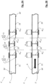
- Figs. 1A and 1B show a part of a sensor system 1 according to a first embodiment of the present invention.
- a sensor unit and a processing unit in general being part of the sensor system 1 of the present invention are not illustrated in the drawings for the sake of simplification.
- the sensor unit and the processing unit are interconnected and are connected to the respective electrodes of the sensor system 1.
- the shown part of the sensor system 1 comprises a tubular fluid channel 2 and a first pair 3 of electrodes 31, 32 at a rigid segment 21 of the fluid channel 2, with the electrodes 31, 32 being fixed with respect to each other and attached to, e.g. printed onto, an outer circumference 25 of a wall 24 of the fluid channel 2 at the rigid segment 21.
- the sensor system 1 comprises a second pair 4 of electrodes 41, 42 at an elastic segment 22 of the fluid channel 2, with the electrodes 41, 42 being arranged in a moveable manner with respect to each other and attached to, e.g. printed onto, an outer circumference 25 of a wall 24 of the fluid channel 2 at the elastic segment 22. Accordingly, a bidirectional flow 6 of a fluid within the fluid channel 2 can be measured through change of capacitance of the electrode pair 4 caused by the change in distance between these electrodes 41, 42. This change in distance is generated by elastic deformation of the elastic segment 22 caused by an increase of fluid pressure of a fluid flowing within the fluid channel 2.
- the electrodes 41, 42 of the second electrode pair 4 are made of a stretchable material, or in a stretchable fashion, in order to be able to compensate for any expansion/contraction of the elastic segment 22.
- the sensor system 1 further comprises a third pair 5 of electrodes 51, 52 at a further rigid segment 23 of the fluid channel 2, with the electrodes 51, 52 being fixed with respect to each other and attached to an outer circumference 25 of a wall 24 of the fluid channel 2 at the rigid segment 23.
- the third pair 5 of electrodes 51, 52 is optional and is not necessarily required for carrying out the present invention; however, providing the third electrode pair 5 can account for the detection of a further change of the fluid flowing within the fluid channel 2. Accordingly, in figs.
- the part of the fluid channel 2 show in these illustrations comprises the first rigid segment 21, the elastic segment 22 and the further rigid segment 23, wherein transition areas between those segments are without substantial interruption, and the wall 24 of the fluid channel 2 is substantially continuous, in particular in order to avoid any disturbances of the fluid flowing inside the fluid channel 2.
- a diameter of the fluid channel 2 at the elastic segment 22 is smaller than a diameter at the rigid segment 21 or as a diameter at the rigid segment 23.
- the difference in diameters can also be gathered from figs. 1A and 1B in the difference in distances between the respective electrodes, i.e. a distance d 1st between the electrodes 31, 32 of the first pair 3 of electrodes 31, 32 provided at the left rigid segment 21 is larger than a distance d 2nd between the electrodes 41, 42 of the second pair 4 of electrodes 41, 42 provided at the elastic segment 22 arranged in between the rigid segment 21 on the left side and the further rigid segment 23 on the right side of figs. 1A and 1B .
- a distance d 3rd between the electrodes 51, 52 of the third pair 5 of electrodes 51, 52 provided at the rigid segment 23 arranged at the right side in the drawings is larger than a distance d 2nd between the electrodes 41, 42 of the second pair 4 of electrodes 41, 42 provided at the elastic segment 22 arranged in between the rigid segments 21, 23.
- the distances d 1st and d 3rd of the rigid segments 21, 23, i.e. their diameters coincide with each other, for the sake of simplification; the distances d 1st and d 3rd of the rigid segments 21, 23, however, can also differ from each other, as long as their exact dimensions are known.
- the different segments 21, 22, 23 are illustratively separated from each other by means of linear dotted lines.
- the sensor system 1 may already comprise a fluid, such as a liquid to be measured, inside the fluid channel 2.
- fig. 1A shows an initial state of the sensor system 1, in which there is no fluid flow within the fluid channel 2.
- fluid flow 6 is present within the fluid channel 2, which can be gathered by the enlarged distance d 2nd , which can also be referred to as d 2nd_moved , between the electrodes 41, 42 attached to the outer circumference 25 of the wall 24 of the fluid channel 2 at the elastic segment 22, compared to the distance d 2nd between the electrodes 41, 42 in the initial state as depicted in fig.
- d 2nd_unmoved which can also be referred to as d 2nd_unmoved .
- the fluid flow 6 to be measured can flow in either direction within the fluid channel 2, since, thus, either electrode pair 3, 5 can be used as reference value.
- it can be gathered from the differing distances d 2nd between the electrodes 41, 42 in the initial state as depicted in fig. 1A and the enlarged state as depicted in fig. 1B that fig. 1A shows a state of the sensor system 1 before expansion, and that fig. 1B shows a state of the sensor system 1 during fluid flow 6, i.e. after expansion of the elastic segment 22.
- the surface areas A 1st of the electrodes 31, 32 of the first pair 3 of electrodes 31, 32 illustrated in the drawings of figs. 1A and 1B in a lateral dimension of the surface area A 1st , coincide with each other, in order to achieve a clear capacitor relationship between these electrodes.
- the surface areas A 2nd of the electrodes 41, 42 of the second pair 4 of electrodes 41, 42 coincide with each other, and the surface areas A 3rd of the electrodes 51, 52 of the third pair 5 of electrodes 51, 52 also coincide with each other, for the same reason.
- the distance d 2nd between the electrodes 41, 42 of the second electrode pair 4, i.e. the only moveable electrode pair in the present embodiment compared to the fixed electrode pairs 3, 5, can be calculated based on the measured capacitances of the fixed electrode pairs 3, 5. Repeating this calculation over time results in a timely progression of the distance d 2nd , which timely progression represents a change of fluid pressure of the fluid flowing within the elastic segment 22 of the fluid channel 2.
- monitoring the timely progression of the distance d 2nd corresponds to the monitoring of a timely progression of the fluid pressure of the fluid flowing within the elastic segment 22 of the fluid channel 2.
- the electrodes 31, 32, 41, 42, 51, 52 of the electrode pairs 3, 4, 5 are depicted as plate-like components in a cross-sectional view.
- the electrodes 31, 32, 41, 42, 51, 52 of the electrode pairs 3, 4, 5 can have a generally plate-like shape, which shape can follow the tubular curvature of the outer circumference 25 of the wall 24 of the fluid channel 2 at least in part.
- the overall dimensions and shapes of the opposing electrodes 31 and 32, 41 and 42, 51 and 52 correspond to each other, in order to achieve a clear capacitor relationship between these electrodes 31 and 32, 41 and 42, 51 and 52 of each electrode pair 3, 4 and 5.
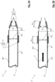
- a sensor system 1' in accordance with a second or modified embodiment of the sensor system as described herein is depicted.
- the moveable electrode pair is implemented by means of a pair 4' of electrodes 41', 42' consisting of a fixed electrode 41' and a moveable electrode 42'.
- This can also be gathered from figs. 2A and 2B when comparing the change in diameter d' 2nd between the electrodes 41', 42' in an initial state as depicted in fig. 2A and in an enlarged state as depicted in fig. 2B .
- the remaining parts of the sensor system 1' of the second embodiment are basically identical to the respective parts of the sensor system 1 as illustrated in figs. 1A and 1B and as described above.
- figs. 2A and 2B show only a part of the sensor system 1' according to the second embodiment of the present invention, wherein a sensor unit and a processing unit in general being part of the sensor system 1' of the present invention are again not illustrated in the drawings for the sake of simplification.
- the sensor unit and the processing unit are interconnected and are connected to the respective electrodes of the sensor system 1.
- the sensor system 1' comprises a second pair 4' of electrodes 41', 42' at an elastic segment 22' of the fluid channel 2', with the electrodes 41', 42' being arranged opposing each other, and wherein the electrode 41' constitutes a fixed electrode 41' and the electrode 42' constitutes a moveable electrode 42' arranged in moveable manner with respect to the fixed electrode 41'.
- both electrodes 41' and 42' are attached to an outer circumference 25' of a wall 24' of the fluid channel 2' at the elastic segment 22'.
- the flow 6 of a fluid within the fluid channel 2' can be measured through change of capacitance of the electrode pair 4' caused by the change in distance between these electrodes 41', 42'.
- This change in distance is generated by elastic deformation of the elastic segment 22' caused by an increase of fluid pressure of a fluid flowing within the fluid channel 2'.
- the sensor system 1' further comprises a third pair 5 of electrodes 51, 52 at a further rigid segment 23 of the fluid channel 2', with the electrodes 51, 52 being fixed with respect to each other and attached to an outer circumference 25' of a wall 24' of the fluid channel 2' at the rigid segment 23.
- the third pair 5 of electrodes 51, 52 is optional and is not necessarily required for carrying out the present invention; however, providing the third electrode pair 5 can account for the detection of a further change of the fluid flowing within the fluid channel 2'.
- the part of the fluid channel 2' show in these illustrations comprises the first rigid segment 21, the elastic segment 22' and the further rigid segment 23, wherein transition areas between those segments are without substantial interruption, and the wall 24' of the fluid channel 2' is substantially continuous, in particular in order to avoid any disturbances of the fluid flowing inside the fluid channel 2'.
- a diameter of the fluid channel 2' at the elastic segment 22' is smaller than a diameter at the rigid segment 21 or as a diameter at the rigid segment 23.
- the difference in diameters can also be gathered from figs. 2A and 2B in the difference in distances between the respective electrodes, i.e. a distance d 1st between the electrodes 31, 32 of the first pair 3 of electrodes 31, 32 provided at the left rigid segment 21 is larger than a distance d' 2nd between the electrodes 41', 42' of the second pair 4' of electrodes 41', 42' provided at the elastic segment 22' arranged in between the rigid segment 21 on the left side and the further rigid segment 23 on the right side of figs.
- a distance d 3rd between the electrodes 51, 52 of the third pair 5 of electrodes 51, 52 provided at the right rigid segment 23 is larger than a distance d' 2nd between the electrodes 41', 42' of the second pair 4' of electrodes 41', 42' provided at the elastic segment 22' arranged in between the rigid segments 21, 23.
- the distances d 1st and d 3rd of the rigid segments 21, 23, i.e. their diameters coincide with each other, for the sake of simplification; the distances d 1st and d 3rd of the rigid segments 21, 23, however, can also differ from each other, as long as their exact dimensions are known.
- the different segments 21, 22', 23 are again illustratively separated from each other by means of linear dotted lines.
- the sensor system 1' may already comprise a fluid, such as a liquid to be measured, inside the fluid channel 2'.
- fig. 2A shows an initial state of the sensor system 1', in which there is no fluid flow within the fluid channel 2'.
- fluid flow 6 is present within the fluid channel 2', which can be gathered by the enlarged distance d' 2nd , which can also be referred to as d' 2nd_moved , compared to the distance d' 2nd between the electrodes 41', 42' in the initial state as depicted in fig. 2A , which can also be referred to as d' 2nd_unmoved .
- the fluid flow 6 to be measured can flow in either direction within the fluid channel 2', since, thus, either electrode pair 3, 5 can be used as reference value.
- it can be gathered from the differing distances d' 2nd between the electrodes 41', 42' in the initial state as depicted in fig. 2A and the enlarged state as depicted in fig. 2B that fig. 2A shows a state of the sensor system 1' before expansion, and that fig. 1B shows a state of the sensor system 1' during fluid flow 6, i.e. after expansion of the elastic segment 22'.
- the electrode 41' is constituted by a fixed electrode, and the respective part of the wall 24' of the fluid channel 2' is, thus, also fixedly arranged, the lower part of the wall 24' of the fluid channel 2' at which the loveable electrode 2' is arranged is the part of the fluid channel 2' which expands in line with the fluid pressure within the fluid channel 2'.
- the surface areas A 1st of the electrodes 31, 32 of the first pair 3 of electrodes 31, 32 illustrated in the drawings of figs. 2A and 2B in a lateral dimension of the surface area A 1st , coincide with each other, in order to achieve a clear capacitor relationship between these electrodes.
- the surface areas A' 2nd of the electrodes 41', 42' of the second pair 4' of electrodes 41', 42' coincide with each other, and the surface areas A 3rd of the electrodes 51, 52 of the third pair 5 of electrodes 51, 52 also coincide with each other, for the same reason.
- the distance d' 2nd between the electrodes 41', 42' of the second electrode pair 4' i.e. the only electrode pair in the present embodiment with variable distance in between electrodes compared to the fixed electrode pairs 3, 5 can be calculated based on the measured capacitances of the fixed electrode pairs 3, 5.
- Repeating this calculation over time results in a timely progression of the distance d' 2nd , which timely progression represents a change of fluid pressure of the fluid flowing within the elastic segment 22' of the fluid channel 2'.
- monitoring the timely progression of the distance d' 2nd corresponds to the monitoring of a timely progression of the fluid pressure of the fluid flowing within the elastic segment 22' of the fluid channel 2'.
- the electrodes 31, 32, 41', 42', 51, 52 of the electrode pairs 3, 4', 5 are depicted as plate-like components in a cross-sectional view.
- the electrodes 31, 32, 41', 42', 51, 52 of the electrode pairs 3, 4', 5 can have a generally plate-like shape, which shape can follow the tubular curvature of the outer circumference 25' of the wall 24' of the fluid channel 2' at least in part.
- the overall dimensions and shapes of the opposing electrodes 31 and 32, 41' and 42', 51 and 52 correspond to each other, in order to achieve a clear capacitor relationship between these electrodes 31 and 32, 41' and 42', 51 and 52 of each electrode pair 3, 4' and 5.
- Figs. 3A and 3B show a part of a sensor system 1" according to a third embodiment of the present invention.
- a sensor unit and a processing unit being, in general, part of the sensor system 1" of the present invention are not illustrated in the drawings for the sake of simplification.
- the sensor unit and the processing unit of the presently described embodiment are interconnected and are connected to the respective electrodes of the sensor system 1". Now, the part of the sensor system 1" shown in figs.
- 3A and 3B comprises a tubular fluid channel 2" and a first pair 3 of electrodes 31, 32 arranged at a rigid segment 21 of the fluid channel 2', with the electrodes 31, 32 being fixed with respect to each other and attached to an outer circumference 25" of a wall 24" of the fluid channel 2" at the rigid segment 21.
- the sensor system 1" comprises a second pair 4" of electrodes 41", 42" at an elastic segment 22" of the fluid channel 2", with the electrodes 41", 42” being arranged in a moveable manner with respect to each other and attached to an outer circumference 25" of a wall 24" of the fluid channel 2" at the elastic segment 22".
- the elastic segment 22" does not exhibit a continuous diameter but rather a converging shape with a decreasing diameter when viewed from left to right in figs. 3A and 3B , contrary to the above-described first and second embodiments.
- the elastic segment 22" constitutes a nozzle-like shape, with the wall 24" reducing its diameter so that, in cross-section, the wall 24" converges into a sharp angle.
- the wall 24" actually closes up at the downstream end of the elastic segment 22", thereby constituting an angle, in cross-section, of e.g. 30°-40°, depending on the length of the elastic segment 22". Accordingly, the electrodes 41", 42" attached to the outer circumference 25" of the wall 24" of the fluid channel 2" also take the same angle relative to each other, thereby constituting an angled positional relationship. Concerning the forming of a plate-like capacitor, the same is also achieved by means of an angled relative positioning of the electrodes, as known to the skilled person. In fig. 3B , an active state of the fluid channel 2" is shown, i.e.
- a fluid is flowing through the fluid channel 2" in a direction from the rigid segment 21 to the elastic segment 22", thereby opening up the closed end of the elastic segment 22" and moving the electrodes 41", 42" away from each other.
- the fluid can only flow in the direction from the rigid segment 21 to the elastic segment 22", since the closed end of the elastic segment 22" as depicted in fig. 3B does not allow entry of fluid from the right side in the drawing, resulting in the elastic segment 22" being arranged downstream of the rigid segment 21.
- the flow 7 of the fluid within the fluid channel 2" can be measured through change of capacitance of the electrode pair 4" caused by the change in distance between these electrodes 41", 42" due to the angle-widening movement of the elastic segment 22".
- This change in distance is again allowed by elastic deformation of the elastic segment 22" caused by an increase of fluid pressure of the fluid flowing within the fluid channel 2".
- no further electrode pair is used, contrary to the previously described embodiments. Accordingly, in figs.
- the part of the fluid channel 2" show in these illustrations comprises the first rigid segment 21 and the nozzle-like elastic segment 22", wherein a transition area between those segments is again implemented without substantial interruption, and the wall 24" of the fluid channel 2" is substantially continuous, in particular in order to avoid any disturbances of the fluid flowing inside the fluid channel 2".
- a diameter of the fluid channel 2" at the elastic segment 22" in a position at which the electrodes 41", 42' are arranged is smaller than a diameter at the rigid segment 21.
- the difference in diameter can also be gathered from figs. 3A and 3B in the difference in distances between the respective electrodes, i.e. a distance d 1st between the electrodes 31, 32 of the first pair 3 of electrodes 31, 32 provided at the rigid segment 21 at the left side is larger than a distance d" 2nd between the electrodes 41", 42" of the second pair 4" of electrodes 41", 42” provided at the elastic segment 22" arranged on the right side of figs. 3A and 3B .
- the different segments 21, 22" of the fluid channel 2" are illustratively separated from each other by means of a linear dotted line.
- the sensor system 1" may already comprise a fluid, such as a liquid to be measured, inside the fluid channel 2", however with a closed end of the elastic segment 2" at its downstream end.
- fig. 3A shows an initial state of the sensor system 1", in which there is no fluid flow within the fluid channel 2".
- unidirectional fluid flow 7 is present within the fluid channel 2", which can be gathered by the enlarged distance d" 2nd , which can also be referred to as d" 2nd_moved , between the electrodes 41", 42" attached to the outer circumference 25" of the wall 24" of the fluid channel 2" at the elastic segment 22", and the opening of the downstream end of the elastic segment 22", compared to the distance d" 2nd between the electrodes 41", 42" in the initial state as depicted in fig. 3A , , which can also be referred to as d" 2nd_unmoved .
- fig. 3A shows a state of the sensor system 1" before expansion
- fig. 3B shows a state of the sensor system 1" during fluid flow 7, i.e. after opening expansion of the elastic segment 22".
- the surface areas A 1st of the electrodes 31, 32 of the first pair 3 of electrodes 31, 32 illustrated in the drawings of figs. 3A and 3B in a lateral dimension of the surface area A 1st , coincide with each other, in order to achieve a clear capacitor relationship between these electrodes.
- the surface areas A" 2nd of the electrodes 41", 42" of the second pair 4" of electrodes 41", 42" coincide with each other.
- the moveable electrode pair in the present embodiment compared to the fixed electrode pair 3 can be calculated based on the measured capacitance of the fixed electrode pair 3. Repeating this calculation over time results in a timely progression of the distance d" 2nd , which timely progression represents a change of fluid pressure of the fluid flowing within the elastic segment 22" of the fluid channel 2". Thus, monitoring the timely progression of the distance d" 2nd corresponds to the monitoring of a timely progression of the fluid pressure of the fluid flowing within the elastic segment 22" of the fluid channel 2".
- the electrodes 31, 32, 41", 42" of the electrode pairs 3, 4" are depicted as plate-like components in a cross-sectional view.
- the electrodes 31, 32, 41", 42" of the electrode pairs 3, 4" can have a generally plate-like shape, which shape can follow the tubular curvature of the outer circumference 25" of the wall 24" of the fluid channel 2" at least in part.
- the overall dimensions and shapes of the opposing electrodes 31 and 32 and 41" and 42" correspond to each other.
- fig. 4 shows a flowchart of a method for determining the flow rate of a fluid flow within a fluid channel by means of a sensor system as described above, wherein step S1 constitutes a step of detecting a capacitance of the first pair of electrodes, such as the capacitance generated between the electrodes of the fixed electrode pair, step S2 constitutes a step of detecting a capacitance of the second pair of electrodes, such as the capacitance generated between the electrodes of the moveable electrode pair, step S3 constitutes a step of calculating a distance between the electrodes of the second pair of electrodes based on the detected capacitance of the first pair of electrodes and the capacitance of the second pair of electrodes, and step S4 constitutes a step of determining a flow rate of the fluid flow within the fluid channel based on a difference in distance between the electrodes of the second pair of electrodes over time.
- steps S1 and S2 can be carried-out by the sensor unit of the respective sensor system, and steps S3 and S4 can be carried-out by a processing unit of the respective sensor system.
- steps S1 and S2 can be carried out simultaneously, whereas steps S3 and S4 are carried-out subsequently.
- any one of steps S1 and S2 can include the detection of the capacitances of several pairs of electrodes, such as, for step S1, the detection of the capacitances of several pairs of fixed electrodes provided at different rigid segments of the respective fluid channel, and, for step S2, the detection of the capacitances of several pairs of moveable electrodes provided at different elastic segments of the respective fluid channel.
- an elasticity of a respective elastic segment of the fluid channel can be adjusted based on the expected flow rate within the fluid channel beforehand, i.e. in advance before carrying out the described method, for example in the form of an optional pre-step S0.
- the elasticity, i.e. the elastic modulus, of the elastic segment can be adjusted to the estimated or expected flow rates of the fluid within the fluid channel, and/or can be adjusted to the expected pressure changes within the fluid channel, so that a respective impact on the measured fluid can be minimized.
Landscapes
- Physics & Mathematics (AREA)
- Fluid Mechanics (AREA)
- General Physics & Mathematics (AREA)
- Electromagnetism (AREA)
- Chemical & Material Sciences (AREA)
- Chemical Kinetics & Catalysis (AREA)
- Electrochemistry (AREA)
- Measuring Volume Flow (AREA)
- Indicating Or Recording The Presence, Absence, Or Direction Of Movement (AREA)
Claims (15)
- Système de capteur (1 ; 1' ; 1") pour déterminer un débit d'un écoulement de fluide (6 ; 7) à l'intérieur d'un canal de fluide (2 ; 2' ; 2"), avecle canal de fluide (2 ; 2' ; 2"), de préférence sous la forme d'un tube de fluide, le canal de fluide (2 ; 2' ; 2") comprenant un segment élastique (22, 22', 22") disposé à proximité d'au moins un segment rigide (21, 23),au moins une première paire (3) d'électrodes (31, 32), les électrodes (31, 32) de la première paire (3) d'électrodes (31, 32) étant disposées à l'opposé l'une de l'autre,au moins une deuxième paire (4 ; 4' ; 4") d'électrodes (41, 42 ; 41', 42' ; 41", 42") fournie au niveau dudit segment élastique (22, 22', 22") du canal de fluide (2 ; 2' ; 2"), les électrodes (41, 42 ; 41', 42' ; 41", 42") de la deuxième paire (4 ; 4' ; 4") d'électrodes (41, 42 ; 41', 42' ; 41", 42") étant disposées à l'opposé l'une de l'autre, etune unité de capteur pour détecter une capacité de la première paire (3) d'électrodes (31, 32) et de la deuxième paire (4 ; 4' ; 4") d'électrodes (41, 42 ; 41', 42' ; 41", 42"),caractérisé en ce queladite première paire (3) d'électrodes (31, 32) est fournie au niveau dudit segment rigide (21) du canal de fluide (2 ; 2' ; 2"), la première paire (3) d'électrodes (31, 32) étant en contact avec ledit segment rigide (21) du canal de fluide (2 ; 2' ; 2"), et dans lequel la deuxième paire (4 ; 4' ; 4") d'électrodes (41, 42 ; 41', 42' ; 41", 42") est en contact avec ledit segment élastique (22, 22', 22") du canal de fluide (2 ; 2' ; 2"), etle système de capteur (1 ; 1' ; 1") comprend en outre une unité de traitement pour calculer et surveiller une distance (d2ème ; d'2ème ; d"2ème) entre les électrodes (41, 42 ; 41', 42' ; 41", 42") de la deuxième paire (4 ; 4' ; 4") d'électrodes (41, 42 ; 41', 42' ; 41", 42") sur la base de la capacité détectée de la première paire (3) d'électrodes (31, 32) et de la deuxième paire (4 ; 4' ; 4") d'électrodes (41, 42 ; 41', 42' ; 41", 42").
- Système de capteur (1 ; 1' ; 1") selon la revendication 1, dans lequel la première paire (3) d'électrodes (31, 32) est en contact avec une circonférence externe (25 ; 25' ; 25") d'une paroi (24 ; 24' ; 24") du canal de fluide (2 ; 2' ; 2") au niveau du segment rigide (21) et la deuxième paire (4 ; 4' ; 4") d'électrodes (41, 42 ; 41', 42' ; 41", 42") est en contact avec la circonférence externe (25 ; 25' ; 25") de la paroi (24 ; 24' ; 24") du canal de fluide (2 ; 2' ; 2") au niveau du segment élastique (22, 22', 22"), de préférence dans lequel la première paire (3) d'électrodes (31, 32) est fixée à la circonférence externe (25 ; 25' ; 25") de la paroi (24 ; 24' ; 24") du canal de fluide (2 ; 2' ; 2") au niveau du segment rigide (21) et la deuxième paire (4 ; 4' ; 4") d'électrodes (41, 42 ; 41', 42' ; 41", 42") est fixée à la circonférence externe (25 ; 25' ; 25") de la paroi (24 ; 24' ; 24") du canal de fluide (2 ; 2' ; 2") au niveau du segment élastique (22, 22', 22").
- Système de capteur (1 ; 1' ; 1") selon la revendication 1 ou 2, dans lequel les électrodes (41, 42 ; 41', 42' ; 41", 42") de la deuxième paire (4 ; 4' ; 4") d'électrodes (41, 42 ; 41', 42' ; 41", 42") sont disposées de manière mobile l'une par rapport à l'autre.
- Système de capteur (1 ; 1') selon l'une quelconque des revendications précédentes, dans lequel les électrodes (41, 42 ; 41', 42') de la deuxième paire (4 ; 4') d'électrodes (41, 42 ; 41', 42') sont disposées parallèles l'une par rapport à l'autre.
- Système de capteur (1") selon l'une quelconque des revendications 1 à 3, dans lequel les électrodes (41", 42") de la deuxième paire (4") d'électrodes (41", 42") sont disposées d'une manière inclinée l'une par rapport à l'autre.
- Système de capteur (1 ; 1') selon l'une quelconque des revendications 1 à 4, dans lequel le système de capteur (1 ; 1') comprend en outre au moins une troisième paire (5) d'électrodes (51, 52) fournie au niveau d'un autre segment rigide (23) du canal de fluide (2 ; 2' ; 2"), les électrodes (51, 52) de la troisième paire (5) d'électrodes (51, 52) étant disposées à l'opposé l'une de l'autre, et de préférence dans lequel le segment élastique (22, 22', 22") du canal de fluide (2 ; 2' ; 2") est disposé entre le segment rigide (21) présentant la première paire (3) d'électrodes (31, 32) et l'autre segment rigide (23) présentant la troisième paire (5) d'électrodes (51, 52).
- Système de capteur (1 ; 1') selon la revendication 6, dans lequel la troisième paire (5) d'électrodes (51, 52) est en contact avec une circonférence externe (25 ; 25') de la paroi (24 ; 24') du canal de fluide (2 ; 2') au niveau de l'autre segment rigide (23), de préférence dans lequel la troisième paire (5) d'électrodes (51, 52) est fixée à la circonférence externe (25 ; 25') de la paroi (24 ; 24') du canal de fluide (2 ; 2') au niveau de l'autre segment rigide (23).
- Système de capteur selon l'une quelconque des revendications 6 et 7, dans lequel le système de capteur comprend en outre au moins une quatrième paire d'électrodes fournie au niveau d'un autre segment élastique du canal de fluide, les électrodes de la quatrième paire d'électrodes étant disposées à l'opposé l'une de l'autre, et de préférence dans lequel l'autre segment rigide est disposé entre le segment élastique et l'autre segment élastique.
- Système de capteur selon la revendication 8, dans lequel la quatrième paire d'électrodes est en contact avec une circonférence externe de la paroi du canal de fluide au niveau de l'autre segment élastique, de préférence dans lequel la quatrième paire d'électrodes est fixée à la circonférence externe de la paroi du canal de fluide au niveau de l'autre segment élastique.
- Système de capteur (1 ; 1' ; 1") selon l'une quelconque des revendications précédentes, dans lequel l'unité de traitement est conçue pour déterminer un débit de l'écoulement de fluide (6 ; 7) à l'intérieur du canal de fluide (2 ; 2' ; 2") sur la base d'une distance (d2ème ; d'2ème ; d"2ème) entre les électrodes (41, 42 ; 41', 42' ; 41", 42") de la deuxième paire (4 ; 4' ; 4") d'électrodes (41, 42 ; 41', 42' ; 41", 42") au cours du temps.
- Méthode pour déterminer un débit d'un écoulement de fluide (6 ; 7) à l'intérieur d'un canal de fluide (2 ; 2' ; 2") au moyen d'un système de capteur (1 ; 1' ; 1") selon l'une quelconque des revendications précédentes, comprenant les étapes de(S1) détection d'une capacité de la première paire (3) d'électrodes (31, 32),(S2) détection d'une capacité de la deuxième paire (4 ; 4' ; 4") d'électrodes (41, 42 ; 41', 42' ; 41", 42"),(S3) calcul d'une distance (d2ème ; d'2ème ; d"2ème) entre les électrodes (41, 42 ; 41', 42' ; 41", 42") de la deuxième paire (4 ; 4' ; 4") d'électrodes (41, 42 ; 41', 42' ; 41", 42") sur la base de la capacité détectée de la première paire (3) d'électrodes (31, 32) et de la capacité de la deuxième paire (4 ; 4' ; 4") d'électrodes (41, 42 ; 41', 42' ; 41", 42"), et(S4) détermination d'un débit de l'écoulement de fluide (6 ; 7) à l'intérieur du canal de fluide (2 ; 2' ; 2") sur la base d'une différence de distance (d2ème ; d'2ème ; d"2ème) entre les électrodes (41, 42 ; 41', 42' ; 41", 42") de la deuxième paire (4 ; 4' ; 4") d'électrodes (41, 42 ; 41', 42' ; 41", 42") au cours du temps.
- Méthode selon la revendication 11, dans laquelle la distance (d2ème ; d'2ème ; d"2ème) entre les électrodes (41, 42 ; 41', 42' ; 41", 42") de la deuxième paire (4 ; 4' ; 4") d'électrodes (41, 42 ; 41', 42' ; 41", 42") est calculée (S3) au moyen de l'équation suivante
 d1ère = distance entre les électrodes (31, 32) de la première paire (3) d'électrodes (31, 32) ;A1ère = surface des électrodes (31, 32) de la première paire (3) d'électrodes (31, 32) ;d2ème =distance entre les électrodes (41, 42 ; 41', 42' ; 41", 42") de la deuxième paire (4 ; 4' ; 4") d'électrodes (41, 42 ; 41', 42' ; 41", 42") ;A2ème = surface des électrodes (41, 42 ; 41', 42' ; 41", 42") de la deuxième paire (4 ; 4' ; 4") d'électrodes (41, 42 ; 41', 42' ; 41", 42") ;C1ère = capacité détectée de la première paire (3) d'électrodes (31, 32) ; etC2ème = capacité détectée de la deuxième paire (4 ; 4' ; 4") d'électrodes (41, 42 ; 41', 42' ; 41", 42").
 - Méthode selon l'une quelconque des revendications 11 et 12, dans laquelle une différence de distance (d2ème ; d'2ème ; d"2ème) entre les électrodes (41, 42 ; 41', 42' ; 41", 42") de la deuxième paire (4 ; 4' ; 4") d'électrodes (41, 42 ; 41', 42' ; 41", 42") au cours du temps reflète une variation de la pression de fluide à l'intérieur du segment élastique (22, 22', 22") du canal de fluide (2 ; 2' ; 2").
- Méthode selon l'une quelconque des revendications 11 à 13, dans laquelle une élasticité du segment élastique (22, 22', 22") du canal de fluide (2 ; 2' ; 2") est réglée sur la base du débit attendu à l'intérieur du canal de fluide (2 ; 2' ; 2").
- Utilisation d'un système de capteur (1 ; 1' ; 1") selon l'une quelconque des revendications 1 à 10 pour déterminer un débit d'un écoulement de fluide (6 ; 7) à l'intérieur d'un canal de fluide (2 ; 2' ; 2"), dans laquelle un mouvement des électrodes (41, 42 ; 41', 42' ; 41", 42") de la deuxième paire (4 ; 4' ; 4") d'électrodes (41, 42 ; 41', 42' ; 41", 42") l'une vers ou s'éloignant de l'autre représente une mesure directe d'une variation de pression de fluide du fluide s'écoulant à l'intérieur du canal de fluide (2 ; 2' ; 2"), laquelle variation de pression de fluide peut être calculée sous forme de débit du fluide s'écoulant à l'intérieur du canal de fluide (2 ; 2' ; 2").
Priority Applications (2)
| Application Number | Priority Date | Filing Date | Title |
|---|---|---|---|
| EP20210683.7A EP4006499B1 (fr) | 2020-11-30 | 2020-11-30 | Système de capteur de débit, méthode et utilisation de ce système pour déterminer un débit |
| US17/456,946 US12066311B2 (en) | 2020-11-30 | 2021-11-30 | Flow rate sensor system, method for and use of such system for determining a flow rate |
Applications Claiming Priority (1)
| Application Number | Priority Date | Filing Date | Title |
|---|---|---|---|
| EP20210683.7A EP4006499B1 (fr) | 2020-11-30 | 2020-11-30 | Système de capteur de débit, méthode et utilisation de ce système pour déterminer un débit |
Publications (2)
| Publication Number | Publication Date |
|---|---|
| EP4006499A1 EP4006499A1 (fr) | 2022-06-01 |
| EP4006499B1 true EP4006499B1 (fr) | 2024-08-21 |
Family
ID=73646209
Family Applications (1)
| Application Number | Title | Priority Date | Filing Date |
|---|---|---|---|
| EP20210683.7A Active EP4006499B1 (fr) | 2020-11-30 | 2020-11-30 | Système de capteur de débit, méthode et utilisation de ce système pour déterminer un débit |
Country Status (2)
| Country | Link |
|---|---|
| US (1) | US12066311B2 (fr) |
| EP (1) | EP4006499B1 (fr) |
Families Citing this family (3)
| Publication number | Priority date | Publication date | Assignee | Title |
|---|---|---|---|---|
| US12188213B2 (en) * | 2020-12-08 | 2025-01-07 | Watts Regulator Co. | Fluid detection systems and methods using the same |
| US12392919B2 (en) | 2020-12-08 | 2025-08-19 | Watts Regulator Co. | Fluid detection systems and methods using the same |
| US12584298B2 (en) | 2020-12-08 | 2026-03-24 | Watts Regulator Co. | Backflow alert system |
Family Cites Families (5)
| Publication number | Priority date | Publication date | Assignee | Title |
|---|---|---|---|---|
| US4484479A (en) | 1978-04-05 | 1984-11-27 | Richard Eckhardt | Gas flow metering |
| US4694702A (en) * | 1984-09-12 | 1987-09-22 | Tokico Ltd. | Vortex shedding flowmeter |
| WO2014048911A1 (fr) | 2012-09-28 | 2014-04-03 | Biofluidix Gmbh | Capteur de pression capacitatif |
| IL277121B2 (en) * | 2018-03-06 | 2025-06-01 | Ezmems Ltd | Direct implementation of sensors in tubes |
| JP6940433B2 (ja) * | 2018-03-13 | 2021-09-29 | アズビル株式会社 | 容量式電磁流量計 |
-
2020
- 2020-11-30 EP EP20210683.7A patent/EP4006499B1/fr active Active
-
2021
- 2021-11-30 US US17/456,946 patent/US12066311B2/en active Active
Also Published As
| Publication number | Publication date |
|---|---|
| US20220170769A1 (en) | 2022-06-02 |
| EP4006499A1 (fr) | 2022-06-01 |
| US12066311B2 (en) | 2024-08-20 |
Similar Documents
| Publication | Publication Date | Title |
|---|---|---|
| US12066311B2 (en) | Flow rate sensor system, method for and use of such system for determining a flow rate | |
| US6213354B1 (en) | System and method for dispensing fluid droplets of known volume and generating very low fluid flow rates | |
| RU2258921C2 (ru) | Фарадметр | |
| EP2511676B1 (fr) | étalonneur de petit volume et procédé pour fournir un étalonnage à volume variable | |
| EP2031403B1 (fr) | Procédé de surveillance d'un procédé de transfert de fluides | |
| CN103674138B (zh) | 流量测量仪 | |
| CN110967138A (zh) | 非侵入式过程流体压力测量系统 | |
| WO2013192036A1 (fr) | Pompe à course linéaire avec détection de position et systèmes et méthodes associés | |
| EP2901121B1 (fr) | Capteur de pression capacitatif | |
| US7694591B2 (en) | Method and apparatus for evaluating a dosing operation | |
| US10458870B2 (en) | Pressure sensor with real time health monitoring and compensation | |
| US8770010B1 (en) | Integrated detector for detecting bubbles in fluid flow and occlusions in a tube | |
| EP3164679B1 (fr) | Procédé et dispositif de determination de l'impulsion d'un fluide | |
| JP3873084B2 (ja) | 動粘度計 | |
| DE19736178C1 (de) | Vorrichtung zur Erfassung von Phasengrenzen in Fluiden | |
| US12038312B2 (en) | Methods and devices for determination of differential parameters associated with fluid flow within a conduit | |
| EP3130895B1 (fr) | Dispositif de capteur de débit et procédé associé | |
| EP3658864B1 (fr) | Débitmètre de fluide à correction de viscosité | |
| JP4590860B2 (ja) | 塗布装置及びそれを用いた塗布方法 | |
| JP7815587B2 (ja) | マイクロ流体液体送出装置 | |
| JP2011058883A (ja) | 超音波流量計 | |
| KR101933117B1 (ko) | 컬럼의 유량분포 측정장치 및 측정방법 | |
| Abbasnejad et al. | A flexible hair-like laser induced graphitic sensor for low flow rate sensing applications | |
| CN117007137A (zh) | 流量感测装置 | |
| JPS62200229A (ja) | 気体流量測定装置 |
Legal Events
| Date | Code | Title | Description |
|---|---|---|---|
| PUAI | Public reference made under article 153(3) epc to a published international application that has entered the european phase |
Free format text: ORIGINAL CODE: 0009012 |
|
| STAA | Information on the status of an ep patent application or granted ep patent |
Free format text: STATUS: THE APPLICATION HAS BEEN PUBLISHED |
|
| AK | Designated contracting states |
Kind code of ref document: A1 Designated state(s): AL AT BE BG CH CY CZ DE DK EE ES FI FR GB GR HR HU IE IS IT LI LT LU LV MC MK MT NL NO PL PT RO RS SE SI SK SM TR |
|
| STAA | Information on the status of an ep patent application or granted ep patent |
Free format text: STATUS: REQUEST FOR EXAMINATION WAS MADE |
|
| 17P | Request for examination filed |
Effective date: 20221110 |
|
| RBV | Designated contracting states (corrected) |
Designated state(s): AL AT BE BG CH CY CZ DE DK EE ES FI FR GB GR HR HU IE IS IT LI LT LU LV MC MK MT NL NO PL PT RO RS SE SI SK SM TR |
|
| GRAP | Despatch of communication of intention to grant a patent |
Free format text: ORIGINAL CODE: EPIDOSNIGR1 |
|
| STAA | Information on the status of an ep patent application or granted ep patent |
Free format text: STATUS: GRANT OF PATENT IS INTENDED |
|
| RIC1 | Information provided on ipc code assigned before grant |
Ipc: G01F 1/28 20060101ALN20240227BHEP Ipc: G01F 1/22 20060101ALN20240227BHEP Ipc: G01F 1/34 20060101ALI20240227BHEP Ipc: G01F 1/56 20060101ALI20240227BHEP Ipc: G01F 1/64 20060101AFI20240227BHEP |
|
| RIC1 | Information provided on ipc code assigned before grant |
Ipc: G01F 1/28 20060101ALN20240301BHEP Ipc: G01F 1/22 20060101ALN20240301BHEP Ipc: G01F 1/34 20060101ALI20240301BHEP Ipc: G01F 1/56 20060101ALI20240301BHEP Ipc: G01F 1/64 20060101AFI20240301BHEP |
|
| INTG | Intention to grant announced |
Effective date: 20240318 |
|
| GRAS | Grant fee paid |
Free format text: ORIGINAL CODE: EPIDOSNIGR3 |
|
| GRAA | (expected) grant |
Free format text: ORIGINAL CODE: 0009210 |
|
| STAA | Information on the status of an ep patent application or granted ep patent |
Free format text: STATUS: THE PATENT HAS BEEN GRANTED |
|
| AK | Designated contracting states |
Kind code of ref document: B1 Designated state(s): AL AT BE BG CH CY CZ DE DK EE ES FI FR GB GR HR HU IE IS IT LI LT LU LV MC MK MT NL NO PL PT RO RS SE SI SK SM TR |
|
| REG | Reference to a national code |
Ref country code: GB Ref legal event code: FG4D |
|
| REG | Reference to a national code |
Ref country code: CH Ref legal event code: EP |
|
| REG | Reference to a national code |
Ref country code: DE Ref legal event code: R096 Ref document number: 602020036114 Country of ref document: DE |
|
| REG | Reference to a national code |
Ref country code: IE Ref legal event code: FG4D |
|
| REG | Reference to a national code |
Ref country code: LT Ref legal event code: MG9D |
|
| REG | Reference to a national code |
Ref country code: NL Ref legal event code: MP Effective date: 20240821 |
|
| PG25 | Lapsed in a contracting state [announced via postgrant information from national office to epo] |
Ref country code: NO Free format text: LAPSE BECAUSE OF FAILURE TO SUBMIT A TRANSLATION OF THE DESCRIPTION OR TO PAY THE FEE WITHIN THE PRESCRIBED TIME-LIMIT Effective date: 20241121 |
|
| REG | Reference to a national code |
Ref country code: AT Ref legal event code: MK05 Ref document number: 1715895 Country of ref document: AT Kind code of ref document: T Effective date: 20240821 |
|
| PG25 | Lapsed in a contracting state [announced via postgrant information from national office to epo] |
Ref country code: NL Free format text: LAPSE BECAUSE OF FAILURE TO SUBMIT A TRANSLATION OF THE DESCRIPTION OR TO PAY THE FEE WITHIN THE PRESCRIBED TIME-LIMIT Effective date: 20240821 Ref country code: PT Free format text: LAPSE BECAUSE OF FAILURE TO SUBMIT A TRANSLATION OF THE DESCRIPTION OR TO PAY THE FEE WITHIN THE PRESCRIBED TIME-LIMIT Effective date: 20241223 Ref country code: PL Free format text: LAPSE BECAUSE OF FAILURE TO SUBMIT A TRANSLATION OF THE DESCRIPTION OR TO PAY THE FEE WITHIN THE PRESCRIBED TIME-LIMIT Effective date: 20240821 Ref country code: GR Free format text: LAPSE BECAUSE OF FAILURE TO SUBMIT A TRANSLATION OF THE DESCRIPTION OR TO PAY THE FEE WITHIN THE PRESCRIBED TIME-LIMIT Effective date: 20241122 Ref country code: FI Free format text: LAPSE BECAUSE OF FAILURE TO SUBMIT A TRANSLATION OF THE DESCRIPTION OR TO PAY THE FEE WITHIN THE PRESCRIBED TIME-LIMIT Effective date: 20240821 |
|
| PG25 | Lapsed in a contracting state [announced via postgrant information from national office to epo] |
Ref country code: BG Free format text: LAPSE BECAUSE OF FAILURE TO SUBMIT A TRANSLATION OF THE DESCRIPTION OR TO PAY THE FEE WITHIN THE PRESCRIBED TIME-LIMIT Effective date: 20240821 |
|
| PG25 | Lapsed in a contracting state [announced via postgrant information from national office to epo] |
Ref country code: LV Free format text: LAPSE BECAUSE OF FAILURE TO SUBMIT A TRANSLATION OF THE DESCRIPTION OR TO PAY THE FEE WITHIN THE PRESCRIBED TIME-LIMIT Effective date: 20240821 |
|
| PG25 | Lapsed in a contracting state [announced via postgrant information from national office to epo] |
Ref country code: AT Free format text: LAPSE BECAUSE OF FAILURE TO SUBMIT A TRANSLATION OF THE DESCRIPTION OR TO PAY THE FEE WITHIN THE PRESCRIBED TIME-LIMIT Effective date: 20240821 Ref country code: IS Free format text: LAPSE BECAUSE OF FAILURE TO SUBMIT A TRANSLATION OF THE DESCRIPTION OR TO PAY THE FEE WITHIN THE PRESCRIBED TIME-LIMIT Effective date: 20241221 |
|
| PG25 | Lapsed in a contracting state [announced via postgrant information from national office to epo] |
Ref country code: HR Free format text: LAPSE BECAUSE OF FAILURE TO SUBMIT A TRANSLATION OF THE DESCRIPTION OR TO PAY THE FEE WITHIN THE PRESCRIBED TIME-LIMIT Effective date: 20240821 |
|
| PG25 | Lapsed in a contracting state [announced via postgrant information from national office to epo] |
Ref country code: ES Free format text: LAPSE BECAUSE OF FAILURE TO SUBMIT A TRANSLATION OF THE DESCRIPTION OR TO PAY THE FEE WITHIN THE PRESCRIBED TIME-LIMIT Effective date: 20240821 Ref country code: RS Free format text: LAPSE BECAUSE OF FAILURE TO SUBMIT A TRANSLATION OF THE DESCRIPTION OR TO PAY THE FEE WITHIN THE PRESCRIBED TIME-LIMIT Effective date: 20241121 |
|
| PG25 | Lapsed in a contracting state [announced via postgrant information from national office to epo] |
Ref country code: RS Free format text: LAPSE BECAUSE OF FAILURE TO SUBMIT A TRANSLATION OF THE DESCRIPTION OR TO PAY THE FEE WITHIN THE PRESCRIBED TIME-LIMIT Effective date: 20241121 Ref country code: PT Free format text: LAPSE BECAUSE OF FAILURE TO SUBMIT A TRANSLATION OF THE DESCRIPTION OR TO PAY THE FEE WITHIN THE PRESCRIBED TIME-LIMIT Effective date: 20241223 Ref country code: PL Free format text: LAPSE BECAUSE OF FAILURE TO SUBMIT A TRANSLATION OF THE DESCRIPTION OR TO PAY THE FEE WITHIN THE PRESCRIBED TIME-LIMIT Effective date: 20240821 Ref country code: NO Free format text: LAPSE BECAUSE OF FAILURE TO SUBMIT A TRANSLATION OF THE DESCRIPTION OR TO PAY THE FEE WITHIN THE PRESCRIBED TIME-LIMIT Effective date: 20241121 Ref country code: NL Free format text: LAPSE BECAUSE OF FAILURE TO SUBMIT A TRANSLATION OF THE DESCRIPTION OR TO PAY THE FEE WITHIN THE PRESCRIBED TIME-LIMIT Effective date: 20240821 Ref country code: LV Free format text: LAPSE BECAUSE OF FAILURE TO SUBMIT A TRANSLATION OF THE DESCRIPTION OR TO PAY THE FEE WITHIN THE PRESCRIBED TIME-LIMIT Effective date: 20240821 Ref country code: IS Free format text: LAPSE BECAUSE OF FAILURE TO SUBMIT A TRANSLATION OF THE DESCRIPTION OR TO PAY THE FEE WITHIN THE PRESCRIBED TIME-LIMIT Effective date: 20241221 Ref country code: HR Free format text: LAPSE BECAUSE OF FAILURE TO SUBMIT A TRANSLATION OF THE DESCRIPTION OR TO PAY THE FEE WITHIN THE PRESCRIBED TIME-LIMIT Effective date: 20240821 Ref country code: GR Free format text: LAPSE BECAUSE OF FAILURE TO SUBMIT A TRANSLATION OF THE DESCRIPTION OR TO PAY THE FEE WITHIN THE PRESCRIBED TIME-LIMIT Effective date: 20241122 Ref country code: FI Free format text: LAPSE BECAUSE OF FAILURE TO SUBMIT A TRANSLATION OF THE DESCRIPTION OR TO PAY THE FEE WITHIN THE PRESCRIBED TIME-LIMIT Effective date: 20240821 Ref country code: ES Free format text: LAPSE BECAUSE OF FAILURE TO SUBMIT A TRANSLATION OF THE DESCRIPTION OR TO PAY THE FEE WITHIN THE PRESCRIBED TIME-LIMIT Effective date: 20240821 Ref country code: BG Free format text: LAPSE BECAUSE OF FAILURE TO SUBMIT A TRANSLATION OF THE DESCRIPTION OR TO PAY THE FEE WITHIN THE PRESCRIBED TIME-LIMIT Effective date: 20240821 Ref country code: AT Free format text: LAPSE BECAUSE OF FAILURE TO SUBMIT A TRANSLATION OF THE DESCRIPTION OR TO PAY THE FEE WITHIN THE PRESCRIBED TIME-LIMIT Effective date: 20240821 |
|
| PG25 | Lapsed in a contracting state [announced via postgrant information from national office to epo] |
Ref country code: RO Free format text: LAPSE BECAUSE OF FAILURE TO SUBMIT A TRANSLATION OF THE DESCRIPTION OR TO PAY THE FEE WITHIN THE PRESCRIBED TIME-LIMIT Effective date: 20240821 Ref country code: SM Free format text: LAPSE BECAUSE OF FAILURE TO SUBMIT A TRANSLATION OF THE DESCRIPTION OR TO PAY THE FEE WITHIN THE PRESCRIBED TIME-LIMIT Effective date: 20240821 Ref country code: DK Free format text: LAPSE BECAUSE OF FAILURE TO SUBMIT A TRANSLATION OF THE DESCRIPTION OR TO PAY THE FEE WITHIN THE PRESCRIBED TIME-LIMIT Effective date: 20240821 |
|
| PG25 | Lapsed in a contracting state [announced via postgrant information from national office to epo] |
Ref country code: EE Free format text: LAPSE BECAUSE OF FAILURE TO SUBMIT A TRANSLATION OF THE DESCRIPTION OR TO PAY THE FEE WITHIN THE PRESCRIBED TIME-LIMIT Effective date: 20240821 |
|
| PG25 | Lapsed in a contracting state [announced via postgrant information from national office to epo] |
Ref country code: CZ Free format text: LAPSE BECAUSE OF FAILURE TO SUBMIT A TRANSLATION OF THE DESCRIPTION OR TO PAY THE FEE WITHIN THE PRESCRIBED TIME-LIMIT Effective date: 20240821 |
|
| PG25 | Lapsed in a contracting state [announced via postgrant information from national office to epo] |
Ref country code: SK Free format text: LAPSE BECAUSE OF FAILURE TO SUBMIT A TRANSLATION OF THE DESCRIPTION OR TO PAY THE FEE WITHIN THE PRESCRIBED TIME-LIMIT Effective date: 20240821 Ref country code: IT Free format text: LAPSE BECAUSE OF FAILURE TO SUBMIT A TRANSLATION OF THE DESCRIPTION OR TO PAY THE FEE WITHIN THE PRESCRIBED TIME-LIMIT Effective date: 20240821 |
|
| REG | Reference to a national code |
Ref country code: DE Ref legal event code: R097 Ref document number: 602020036114 Country of ref document: DE |
|
| PLBE | No opposition filed within time limit |
Free format text: ORIGINAL CODE: 0009261 |
|
| STAA | Information on the status of an ep patent application or granted ep patent |
Free format text: STATUS: NO OPPOSITION FILED WITHIN TIME LIMIT |
|
| PG25 | Lapsed in a contracting state [announced via postgrant information from national office to epo] |
Ref country code: MC Free format text: LAPSE BECAUSE OF FAILURE TO SUBMIT A TRANSLATION OF THE DESCRIPTION OR TO PAY THE FEE WITHIN THE PRESCRIBED TIME-LIMIT Effective date: 20240821 |
|
| PG25 | Lapsed in a contracting state [announced via postgrant information from national office to epo] |
Ref country code: LU Free format text: LAPSE BECAUSE OF NON-PAYMENT OF DUE FEES Effective date: 20241130 |
|
| 26N | No opposition filed |
Effective date: 20250522 |
|
| REG | Reference to a national code |
Ref country code: BE Ref legal event code: MM Effective date: 20241130 |
|
| PG25 | Lapsed in a contracting state [announced via postgrant information from national office to epo] |
Ref country code: SE Free format text: LAPSE BECAUSE OF FAILURE TO SUBMIT A TRANSLATION OF THE DESCRIPTION OR TO PAY THE FEE WITHIN THE PRESCRIBED TIME-LIMIT Effective date: 20240821 |
|
| PG25 | Lapsed in a contracting state [announced via postgrant information from national office to epo] |
Ref country code: BE Free format text: LAPSE BECAUSE OF NON-PAYMENT OF DUE FEES Effective date: 20241130 |
|
| PG25 | Lapsed in a contracting state [announced via postgrant information from national office to epo] |
Ref country code: IE Free format text: LAPSE BECAUSE OF NON-PAYMENT OF DUE FEES Effective date: 20241130 |
|
| REG | Reference to a national code |
Ref country code: CH Ref legal event code: U11 Free format text: ST27 STATUS EVENT CODE: U-0-0-U10-U11 (AS PROVIDED BY THE NATIONAL OFFICE) Effective date: 20251201 |
|
| PGFP | Annual fee paid to national office [announced via postgrant information from national office to epo] |
Ref country code: DE Payment date: 20251022 Year of fee payment: 6 |
|
| PGFP | Annual fee paid to national office [announced via postgrant information from national office to epo] |
Ref country code: GB Payment date: 20251022 Year of fee payment: 6 |
|
| PGFP | Annual fee paid to national office [announced via postgrant information from national office to epo] |
Ref country code: FR Payment date: 20251023 Year of fee payment: 6 |
|
| PGFP | Annual fee paid to national office [announced via postgrant information from national office to epo] |
Ref country code: CH Payment date: 20251201 Year of fee payment: 6 |
|
| PG25 | Lapsed in a contracting state [announced via postgrant information from national office to epo] |
Ref country code: CY Free format text: LAPSE BECAUSE OF FAILURE TO SUBMIT A TRANSLATION OF THE DESCRIPTION OR TO PAY THE FEE WITHIN THE PRESCRIBED TIME-LIMIT; INVALID AB INITIO Effective date: 20201130 |