EP4006501B1 - Dispositif et procédé de surveillance de niveau de remplissage - Google Patents
Dispositif et procédé de surveillance de niveau de remplissage Download PDFInfo
- Publication number
- EP4006501B1 EP4006501B1 EP21206397.8A EP21206397A EP4006501B1 EP 4006501 B1 EP4006501 B1 EP 4006501B1 EP 21206397 A EP21206397 A EP 21206397A EP 4006501 B1 EP4006501 B1 EP 4006501B1
- Authority
- EP
- European Patent Office
- Prior art keywords
- container
- light
- light source
- sensitive sensor
- filling
- Prior art date
- Legal status (The legal status is an assumption and is not a legal conclusion. Google has not performed a legal analysis and makes no representation as to the accuracy of the status listed.)
- Active
Links
Images


Classifications
-
- G—PHYSICS
- G01—MEASURING; TESTING
- G01F—MEASURING VOLUME, VOLUME FLOW, MASS FLOW OR LIQUID LEVEL; METERING BY VOLUME
- G01F23/00—Indicating or measuring liquid level or level of fluent solid material, e.g. indicating in terms of volume or indicating by means of an alarm
- G01F23/22—Indicating or measuring liquid level or level of fluent solid material, e.g. indicating in terms of volume or indicating by means of an alarm by measuring physical variables, other than linear dimensions, pressure or weight, dependent on the level to be measured, e.g. by difference of heat transfer of steam or water
- G01F23/28—Indicating or measuring liquid level or level of fluent solid material, e.g. indicating in terms of volume or indicating by means of an alarm by measuring physical variables, other than linear dimensions, pressure or weight, dependent on the level to be measured, e.g. by difference of heat transfer of steam or water by measuring the variations of parameters of electromagnetic or acoustic waves applied directly to the liquid or fluent solid material
- G01F23/284—Electromagnetic waves
- G01F23/292—Light, e.g. infrared or ultraviolet
- G01F23/2921—Light, e.g. infrared or ultraviolet for discrete levels
- G01F23/2922—Light, e.g. infrared or ultraviolet for discrete levels with light-conducting sensing elements, e.g. prisms
- G01F23/2925—Light, e.g. infrared or ultraviolet for discrete levels with light-conducting sensing elements, e.g. prisms using electrical detecting means
-
- G—PHYSICS
- G01—MEASURING; TESTING
- G01F—MEASURING VOLUME, VOLUME FLOW, MASS FLOW OR LIQUID LEVEL; METERING BY VOLUME
- G01F23/00—Indicating or measuring liquid level or level of fluent solid material, e.g. indicating in terms of volume or indicating by means of an alarm
- G01F23/22—Indicating or measuring liquid level or level of fluent solid material, e.g. indicating in terms of volume or indicating by means of an alarm by measuring physical variables, other than linear dimensions, pressure or weight, dependent on the level to be measured, e.g. by difference of heat transfer of steam or water
- G01F23/28—Indicating or measuring liquid level or level of fluent solid material, e.g. indicating in terms of volume or indicating by means of an alarm by measuring physical variables, other than linear dimensions, pressure or weight, dependent on the level to be measured, e.g. by difference of heat transfer of steam or water by measuring the variations of parameters of electromagnetic or acoustic waves applied directly to the liquid or fluent solid material
- G01F23/284—Electromagnetic waves
- G01F23/292—Light, e.g. infrared or ultraviolet
- G01F23/2921—Light, e.g. infrared or ultraviolet for discrete levels
-
- B—PERFORMING OPERATIONS; TRANSPORTING
- B67—OPENING, CLOSING OR CLEANING BOTTLES, JARS OR SIMILAR CONTAINERS; LIQUID HANDLING
- B67C—CLEANING, FILLING WITH LIQUIDS OR SEMILIQUIDS, OR EMPTYING, OF BOTTLES, JARS, CANS, CASKS, BARRELS, OR SIMILAR CONTAINERS, NOT OTHERWISE PROVIDED FOR; FUNNELS
- B67C3/00—Bottling liquids or semiliquids; Filling jars or cans with liquids or semiliquids using bottling or like apparatus; Filling casks or barrels with liquids or semiliquids
- B67C3/02—Bottling liquids or semiliquids; Filling jars or cans with liquids or semiliquids using bottling or like apparatus
- B67C3/22—Details
- B67C3/28—Flow-control devices, e.g. using valves
- B67C3/282—Flow-control devices, e.g. using valves related to filling level control
- B67C3/284—Flow-control devices, e.g. using valves related to filling level control using non-liquid contact sensing means
Definitions
- the invention relates to a device and a method for monitoring the fill level of containers for a container treatment plant.
- products can be filled using height filling, for example beer in glass containers.
- the filling limit for height filling is set by a short-circuit probe.
- the short-circuit probe can have a metal tube around 100 mm long that protrudes from the filling valve.
- the container to be filled can be lifted up and pressed against the filling valve.
- an electrical signal is triggered which ends the filling process.
- the container can then be lowered again.
- a disadvantage of this technology can be the need for a large lifting movement of the containers (>100 mm) when filling due to the length of the short-circuit probe. This can also be a major problem for CIP cleaning ("cleaning-in-place"). Due to the long short-circuit probes, the CIP caps must also be extremely long and cannot be swung in - as in the standard case - but must perform a combination of swivel and lifting movements. This is also mechanically very complex. Another disadvantage of the short-circuit probe is the risk of contamination being carried over. Since the probe comes into contact with the product in the respective container every time the filling stops, it is possible to transfer germs from a contaminated container to other, still clean containers.
- the DE 10118 323 A1 discloses a device for controlling the fill level of moving, transparent containers, with at least one light-sensitive sensor unit, a light source directed at the sensor unit and an evaluation device for sensor signals from the sensor unit.
- the sensor unit generates sensor signals that depend on the position of a light beam on the sensor unit.
- the evaluation device determines from the temporal sequence of the sensor signals whether the light beam was deflected by a container filled with filling material.
- the GB 1 285 201 A discloses a bottle sorting device for detecting improperly filled transparent bottles or containers.
- the bottle sorting device comprises a projector which projects a beam of light which strikes a bottle or container at a predetermined height, and a photoelectric device mounted behind the bottle or container.
- the photoelectric device has an active area whose outer edge just does not intercept the beam when the container is not filled to the predetermined height. The area is large enough so that the beam always strikes it when the container is filled above the predetermined level.
- a rotating disk having a slot enables the detector to distinguish between ambient light and the light refracted by the bottle.
- the DE 10 2006 019518 A1 discloses a device and a method for filling containers, with at least one filling device that supplies liquid to at least one container to be filled via a filling needle.
- the filling needle is used to completely fill the container.
- a sensor device is provided to monitor the fill level of the liquid supplied to the container.
- the filling device is controlled depending on at least one output signal of the sensor device.
- a drive device is provided that moves the filling needle during the filling process.
- the US 3 094 213 A discloses another system for determining whether a bottle passing through an inspection zone has been properly filled with a liquid.
- the DE 10 2018 133 602 A1 discloses a control device for determining a fill level of a container to be filled with a liquid, in particular for a beverage bottling plant.
- the device comprises a transmitting unit for emitting at least one measuring beam penetrating the container and a receiving unit associated therewith that receives the measuring beam.
- the transmitting unit emits the measuring beam in an ascending direction that is inclined relative to an interface between the liquid and a gas layer arranged above it in the container.
- the transmitting unit and the receiving unit are arranged and set up in such a way that, when the container is at a desired fill level, the measuring beam emitted by the transmitting unit passes through the liquid in the container and strikes the interface in such a way that the interface reflects the measuring beam in a direction deflected by the receiving unit.
- the invention is based on the object of creating an improved level monitoring system for a container treatment plant, preferably with regard to functionality, reliability and/or construction.
- One aspect of the present disclosure relates to a device for monitoring the fill level of containers for a container treatment plant (e.g. for producing, cleaning, testing, filling, closing, labeling, printing and/or packaging containers for liquid media, preferably beverages or liquid foodstuffs).
- the device has a container receptacle for receiving a container.
- the device has a filling device (e.g. having a filling valve) which is arranged for filling (e.g. pressure filling) a container received in the container receptacle with a liquid.
- the device has a (e.g. point-shaped) light source (e.g.
- the device comprises a light-sensitive sensor (e.g. comprising a photodiode, a photoresistor, a phototransistor, a CCD sensor and/or a CMOS sensor) which is arranged to receive the light beam only when the liquid in the container has a fill level (e.g. at the level of the light source, the sensor and/or the light beam) at which the light beam is incident upon passing (or crossing, passing through or penetrating) the container by the liquid in the container.
- a light-sensitive sensor e.g. comprising a photodiode, a photoresistor, a phototransistor, a CCD sensor and/or a CMOS sensor
- a fully formed liquid lens can cause a deflection of the light beam that is large enough to reach the sensor.
- Other typical sources of error in optical measuring methods can be excluded or at least significantly mitigated.
- the influence of liquid drops in or on the container can be reduced or excluded.
- the liquid drops only cause a very small parallel shift of the light beam. This means that an incorrectly triggered filling stop can be ruled out.
- the container wall and, when the wall is filled, a liquid film on the inside of the container only produce minimal light refraction.
- the refracted light beam is not refracted enough to reach the sensor. This is the case until the liquid level (the fill level) has reached the height of the light source as a result of the filling process.
- the light beam is then refracted so strongly by the liquid lens that has formed in the container that the sensor is hit.
- the sensor can - similar to the short-circuit probe - send an electrical signal, for example, which ends the filling process.
- the device can preferably offer a whole range of advantages over conventional systems.
- the level measurement can be non-invasive, which can improve hygiene, e.g. by preventing the spread of product or germs.
- the mechanics can be significantly simplified, for example, compared to filling systems with a short-circuit probe, in particular with regard to CIP caps and a basic structure of the container holder to enable the containers to be lifted.
- the filling process can be shortened overall. For example, in a filler carousel, a process angle saving can be made possible by the shortened stroke, so that a higher output with the same pitch circle or a smaller filler with a given output is possible. There is no influence from foam, as this floats above the liquid level.
- the level measurement can also be used when filling CSD products ("carbonated soft drinks"). Since the level measurement is contactless, it is also safe from wire breakage. Free jet filling can also be made possible because the short-circuit probe can be omitted. Ultimately, cost advantages can also arise, especially compared to the use of a short-circuit probe.
- the container holder can be vertically movable so that a container held in the container holder can be pressed with its filling opening against the filling device, preferably to enable pressure filling by means of the filling device.
- the device has a cover (e.g. detachably attached) that covers (e.g. shades) a section of a light-sensitive sensor surface of the light-sensitive sensor.
- a cover e.g. detachably attached
- covers e.g. shades
- a section of a light-sensitive sensor surface of the light-sensitive sensor instead of a special solution for the light-sensitive sensor with a small sensor surface, a cost-effective (large) standard format for the sensor can be used.
- the sensor surface that is not required can simply be covered by the cover, so that it can be ruled out that there are errors in this area, e.g. due to reflections or ambient light.
- the cover and the large-format sensor can also enable the device to be used with different container formats and/or different desired fill levels, for which different covers can exist or the cover can be adjusted.
- the cover can be arranged between the container holder and the sensor.
- the cover is adjustable, preferably movable, to change the covered section.
- different areas of the sensor surface of the sensor can thus be exposed using a single cover, which can, for example, enable the setting of different desired filling levels and the use of different containers.
- the cover has a first disk (e.g. outer disk) which is rotatably mounted and has a first through hole which is arranged eccentrically in the first disk.
- the cover has a second disk (e.g. inner disk) which is rotatably mounted in the first through hole and has a second through hole which is arranged eccentrically in the second disk for letting the light beam through.
- the disks can advantageously each be rotated in order to adjust a position of the second through hole for the light beam. This advantageously makes it possible to set different desired filling levels and to use different containers.
- the device has a light source protective screen (e.g. shatterproof or scratch-resistant) which is arranged between the light source and the container holder and is designed to protect the light source from container fragments in the event of a container breakage in the container holder.
- a light source protective screen e.g. shatterproof or scratch-resistant
- this can advantageously prevent the light source from being damaged and having to be replaced.
- the device has a sensor protection screen (e.g. shatterproof or scratch-resistant) which is arranged between the light-sensitive sensor and the container holder and is designed to protect the light-sensitive sensor from container fragments in the event of a container breakage in the container holder.
- a sensor protection screen e.g. shatterproof or scratch-resistant
- this can advantageously prevent the sensor from being damaged and having to be replaced.
- the light source is designed to emit the light beam in a predetermined wavelength range.
- the device can also have an optical filter, preferably a bandpass filter and/or polarization filter, which is arranged between the container holder and the light-sensitive sensor and is designed to filter out, preferably partially or completely, a light wavelength range outside the predetermined wavelength range. In this way, an incorrect fill level measurement due to ambient light can preferably be prevented.
- the optical filter can be substantially only permeable to the predetermined wavelength range of the light beam of the light source.
- the optical filter is integrated in the cover (e.g. arranged in the second through hole) and/or integrated in the sensor protective screen. This advantageously creates a solution that is particularly space-efficient.
- the light source and/or the light-sensitive sensor is adjustable, namely pivotable towards and away from the container holder.
- the light source and/or the light-sensitive sensor is height-adjustable.
- the device can also be adapted to different container formats.
- the device has a base frame that (jointly) supports the light source and/or the light-sensitive sensor. This advantageously makes it possible to provide a construction that is easy to assemble and saves space.
- the base frame can also carry a container holder, preferably a container neck clamp, for holding the container in the container holder.
- the device can have, for example, a support base/base plate for supporting the container on the base.
- the support base/base plate can be carried by the base frame or not.
- the base frame can also carry the optical filter, the cover, the sensor protective screen and/or the light source protective screen, e.g. each in a respective receptacle of the base frame.
- the base frame has a first outer leg, a second outer leg and a middle leg.
- the first outer leg, the second outer leg and the middle leg together can form a U-shape.
- the light-sensitive sensor it is possible for the light-sensitive sensor to be arranged on the first outer leg and/or the light source to be arranged on at least one of the second outer leg and the middle leg.
- the ease of assembly and the space-saving arrangement can thus be further improved.
- the container holder is arranged on the middle leg.
- first outer leg and the second outer leg may run substantially parallel.
- the optical filter, the sensor protective screen and/or the cover can be arranged on the first outer leg.
- the light source protective screen can be arranged on the second outer leg.
- first outer leg and/or the second outer leg is movably, preferably pivotably, connected to the middle leg.
- different desired filling levels can be set in this way and/or the device can be adapted to different container formats.
- the device further comprises a deflection mirror which is arranged to deflect the light beam emitted by the light source in a direction towards the container receptacle, preferably in a range between 30° and 150°, particularly preferably around 90°.
- the deflection mirror can advantageously significantly expand the possibilities for arranging the light source, so that it can be arranged in a way that is more space-efficient or easier to assemble, for example.
- the deflection mirror is arranged on the second outer leg and the light source has an elongated body whose longitudinal axis runs substantially parallel to a longitudinal axis of the second outer leg.
- the light source can be arranged at least partially on the middle leg. This can advantageously achieve a space-saving arrangement of the light source.
- the device may further comprise at least one further light source for emitting at least one further light beam to pass through the container accommodated in the container holder, wherein the at least one further light source is arranged vertically offset from (e.g. above or below) the light source.
- the light-sensitive sensor can be arranged to receive the at least one further light beam only when the liquid in the container has a fill level at which the at least one further light beam was refracted by the liquid in the container when passing through the container.
- several fill level measuring points can be checked in this way, e.g. up to a quasi-continuous control of the filling level.
- different filling heights can also be defined in this way for fast filling and slow filling.
- the light sources can be designed as a continuous bar of light points or a light curtain.
- the sensor can expediently be designed as a vertical sensor strip.
- the light-sensitive sensor and the light source are arranged essentially at the same height, and/or the light-sensitive sensor and the light source are arranged on opposite sides of the container holder.
- the sensor and the light source can be arranged in this way in a particularly favorable manner to fulfill their respective functions.
- the device further comprises a control unit which is designed to terminate filling of the container by means of the filling device when the control unit receives a signal from the light-sensitive sensor which indicates that the light beam was received by the light-sensitive sensor.
- control unit can refer to electronics (e.g. with microprocessors) and data storage) which, depending on the design, can take on control tasks and/or regulation tasks and/or processing tasks. Even if the term “control” is used here, it can also appropriately include or mean “regulation” or “control with feedback” and/or “processing”.
- the device is included in a filler carousel for filling containers.
- the filler carousel may have multiple devices as disclosed herein, which are arranged distributed around a circumference of the filler carousel.
- a further aspect of the present disclosure relates to a method for monitoring the fill level of containers for a container treatment plant, preferably by means of a device as disclosed herein.
- the method comprises filling (e.g. pressure filling) a container with a liquid (e.g. by means of a filling device).
- the method comprises emitting a beam of light (e.g. by means of a light source) that passes through the container during filling.
- the method comprises receiving the emitted beam of light by means of a light-sensitive sensor only when the liquid in the container has a fill level at which the emitted beam of light was refracted by the liquid in the container when passing (or crossing, passing through or shining through) the container during filling.
- the method comprises stopping the filling when the emitted beam of light has been received (e.g. by means of a control unit).
- the method can achieve the same advantages that have already been described for the device herein. This also applies to the preferred developments of the method described below.
- the method further comprises covering a portion of a light-sensitive sensor surface of the light-sensitive sensor (e.g. by means of a cover), and preferably changing the covered portion (e.g. by means of an adjustability, preferably mobility, of the cover) (e.g. before and/or during filling).
- the method further comprises protecting the light-sensitive sensor from container fragments in the event of a container breakage (e.g. by means of a protective screen) (e.g. during filling).
- the method may further comprise protecting the light source from container fragments in the event of a container breakage (e.g. by means of a protective screen) (e.g. during filling).
- a protective screen e.g. during filling
- the method further comprises filtering light radiating onto the light-sensitive sensor, wherein light wavelength ranges that are outside a wavelength range of the emitted light beam are preferably partially or completely filtered out (e.g. by means of an optical filter) (e.g. during filling).
- the method further comprises deflecting the emitted light beam by means of a deflection mirror before passing through the container (e.g. during filling).
- Figure 1 shows a device 10.
- the device 10 enables filling and monitoring of a fill level of a container 12.
- the device 10 can be included, for example, in a container treatment plant, e.g. for producing, cleaning, testing, filling, closing, labeling, printing and/or packaging containers for liquid media, preferably drinks or liquid foodstuffs.
- the device 10 is preferably a section of a filling carousel, which has several of the devices 10 distributed around its circumference.
- the container 12 is made of an at least partially translucent or transparent material, for example of a plastic or glass.
- the container 12 preferably has an elongated neck region (for example a so-called long-neck bottle).
- the container 12 can preferably be a bottle, for example a glass bottle or PET bottle.
- the container 12 it is also possible for the container 12 to be designed differently, for example as a canister, a flacon or a vessel.
- the device 10 has a container holder 14, a filling device 16, a light source 18 and a light-sensitive sensor 20.
- the container receptacle 14 is an area or a space in which the container 12 can be positioned.
- the container 12 can preferably be mechanically fed to the container receptacle 14 and/or removed from the container receptacle 14.
- the feeding and removal can be carried out, for example, by means of one or more container conveyors (not shown).
- the container holder 22 can preferably be designed as a (for example active or passive) container neck clamp for holding the container 12 on a neck ring of the container 12 (so-called neck handling).
- the container holder 22, if present, can be designed differently and to support the container 12, for example, on its bottom, e.g. in the form of a support bottom/bottom plate, and/or to hold it on its base.
- the filling device 16 is arranged above the container holder 14.
- the filling device 16 is designed to fill the container 12 positioned in the container holder 14.
- the Filling device 16 can, for example, have a filling valve.
- the container 12 can be filled by the filling device 16 by means of level filling. During level filling, successive containers 12 are always filled to the same fill level, even if the filling volumes can be different.
- the filling device 16 is designed to fill the container 12 by means of a pressure filling (for example with a filling pressure of 5 bar or more).
- the filling device 16 can be connected in a pressure-tight manner to a container opening of the container 12.
- the container 12 can be pressed against the filling device 16 from below, for example by means of a lifting device, such as a lifting table.
- the filling device 16 can be connected to a tank (for example a pressure tank). The liquid for filling the container 12 can be fed from the tank to the filling device 16.
- the light source 18 is arranged laterally next to the container receptacle 14, preferably off-center with respect to the container receptacle 14 and/or the container 12.
- the light source 18 can emit a light beam.
- the light beam can be emitted directly to the container receptacle 14 or can be deflected to the container receptacle 14 by means of at least one deflecting mirror.
- the light beam from the light source 18 hits the container 12 in the container receptacle 14 preferably in the direction of a secant that does not pass through the center axis of the container 12.
- the light source 18 can be, for example, a laser light source, LED light source, UV light source or infrared light source.
- the light source 18 can emit light in a predetermined wavelength range.
- the light source 18 is preferably a point-shaped light source.
- the light source 18 can be arranged so as to be adjustable.
- the light source 18 can be height-adjustable.
- the light source 18 can be moved towards the container holder 14 and away from the container holder 14, for example by pivoting and/or moving the light source 18.
- the light-sensitive sensor 20 is arranged laterally next to the container holder 14, preferably off-center with respect to the container holder 14 and/or the container 12.
- the sensor 20 can preferably be arranged on a side of the container holder 14 opposite the light source 18.
- the sensor 20 and the light source 18 are preferably arranged at the same height.
- the sensor 20 and the light source 18 are preferably arranged at a container neck height of the container 12 in the container holder 14.
- the sensor 20 is designed to output a signal when it receives a light beam on its light-sensitive sensor surface.
- the Figures 2 and 3 show a relative arrangement of the container holder 14, the light source 18 and the sensor 20 to each other.
- the Figure 2 the container 12 with a filling level which is positioned at or above the level of a passage of the light beam from the light source 18 through the container 12.
- the Figure 3 shows the container 12 with a fill level positioned below a passage of the light beam from the light source 18 through the container 12.
- the comparison of the Figures 2 and 3 shows that the sensor 20 only receives the light beam emitted by the light source 18 when the light beam passes through the container 12 in the container holder 14 and the liquid in the container 12 refracts the light beam.
- the liquid in the container 12 can thus form a liquid lens for refracting the light beam (see Figure 2 ).
- the liquid in the container 12 refracts the light beam in a direction towards the sensor 20. If the container 12 is empty or has a filling level that is too low, the light beam is not refracted by the liquid in the container 12, so that the light beam does not reach the sensor 20 (see Figure 3 ).
- the sensor 20 can output a signal during the filling of the container 12 by means of the filling device 16 when the light beam has been received by the light source 18. At this point in time, a fill level of the liquid in the container 12 can thus be determined.
- the signal from the sensor 20 can preferably be used to end the filling of the container 12.
- the sensor 20 may, for example, comprise a photoresistor, a photodiode, a phototransistor, a CCD sensor and/or a CMOS sensor.
- the container holder 14 can move during the filling of the container 12, e.g. on a circular path of a rotary movement of a filling carousel.
- the sensor 20 and/or the light source 18 can move with the container holder 14.
- the sensor 20 and/or the light source 18 can be stationary, e.g. even if the container holder 14 moves during filling.
- a fill level of several containers in several container holders could be checked one after the other. It is also possible for the container holder 14 to be stationary.
- the device 10 may further comprise a control unit 24 (see Figure 1 ), a cover 26, a light source protective screen 28, a sensor protective screen 30 and/or an optical filter 32, if desired.
- the control unit 24 can be in communication with the filling device 16 and the sensor 20.
- the control unit 24 can operate the filling device 16 based on a signal received from the sensor 20.
- the control unit 24 can operate the filling device 16 to stop filling the container 12 when the control unit 24 receives a signal from the sensor 20 indicating that the desired filling level of the container 12 has been reached or will be reached shortly. This can, for example, enable the already explained filling level of the container 12.
- the cover 26 is arranged between the container holder 14 and the sensor 20 with respect to a direction of the light beam.
- the cover 26 can cover or shade a portion of a light-sensitive sensor surface of the sensor 20.
- the cover 26 can have a through hole for the light beam to pass through.
- the cover 26 can preferably be adjustable so that a section of the light-sensitive sensor surface of the sensor 20 covered by the cover 26 can be changed.
- the cover 26 is preferably movable, e.g. displaceable, pivotable and/or rotatable, relative to the sensor 20.
- the cover 26 can have a first rotatable disk in which a second disk with a through hole for the light beam is rotatably mounted, as described by way of example with reference to the Figures 8 to 10 described herein.
- the light source protective screen 28 is arranged between the light source 18 and the container holder 14 with respect to a direction of the light beam.
- the light source protective screen 28 is preferably shatterproof and/or scratch-resistant.
- the light source protective screen 28 can protect the light source 18 from container fragments if the container 12 breaks in the container holder 14, e.g. during pressure filling using the filling device 16.
- the sensor protective screen 30 is arranged between the container holder 14 and the sensor 20 with respect to a direction of the light beam.
- the sensor protective screen 30 is preferably shatterproof and/or scratch-resistant.
- the sensor protective screen 30 can protect the sensor 20, the cover 26 and/or the optical filter 32 from container fragments if the container 12 breaks in the container holder 14, e.g. during pressure filling using the filling device 16.
- the optical filter 32 is arranged between the container holder 14 and the sensor 20 with respect to a direction of the light beam.
- the optical filter 32 is designed to partially or completely filter out incident light.
- the optical filter 32 can filter out wavelength ranges from the incident light (e.g. absorb or reflect) that do not correspond to the predetermined wavelength range of the light beam from the light source 18.
- the optical filter 32 can filter out substantially all wavelength ranges other than the predetermined wavelength range of the light beam from the light source 18 from the incident light.
- the optical filter 32 can preferably be designed as a bandpass filter and/or a polarization filter. Particularly preferably, the optical filter 32 can only be permeable to the wavelength(s) of the light beam from the light source 18.
- the cover 26, the sensor protective disk 30 and/or the optical filter 32 can be connected to the sensor 20. If the sensor 20 moves with the container holder 14, the cover 26, the sensor protective disk 30 and/or the optical filter 32 preferably move with the sensor 20.
- optical filter 32 is integrated into the cover 26 and/or the sensor protective screen 30. It is also possible that the optical filter 32, the cover 26 and/or the sensor protective screen 30 are formed separately from one another.
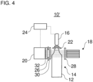
- the Figure 4 shows a modified device 10'.
- the device 10' has a plurality of light sources 18.
- the light sources 18 are arranged vertically offset from one another. It is possible for the light sources 18 to be arranged along an entire height of the container holder 14, or for example only in an upper half, an upper third or an upper quarter of the container holder 14.
- the sensor 20 can be designed, for example, as a sensor strip that receives the respective light rays from the light sources 18 if they have previously been refracted by the liquid in the container 12.
- the sensor 20 can be designed with a continuous light-sensitive sensor surface.
- the sensor 20 can have, for example, several vertically offset light-sensitive sensor surfaces or individual sensors.
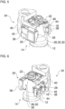
- the Figures 5 to 7 show parts of an embodiment of the device 10.
- a base frame 34 supports the light source 18, the sensor 20 and the container holder 22.
- the base frame 34 can support the cover 26, the light source protective disk 28, the sensor protective disk 30 and the optical filter 32 if present and/or desired. It is also possible for the base frame 34 to support only one or some of the light source 18, sensor 20, container holder 22, cover 26, light source protective disk 28, sensor protective disk 30 and optical filter 32.
- the base frame 34 can, for example, have a substantially U-shape in a plan view.
- the U-shape can be formed by two substantially parallel outer legs 36, 38 and a middle leg 40. It is possible for at least one of the two outer legs 36, 38 to be movably connected to the middle leg 40.
- the first outer leg 36 is pivotally connected to the middle leg 40.
- the base frame 34 can also have any other suitable shape.
- the sensor 20, the cover 26, the sensor protective screen 30 and/or the optical filter 32 can be arranged on the first outer leg 36.
- the first outer leg 36 can each have a preferably slot-shaped receptacle for the sensor 20, the cover 26, the sensor protective screen 30 and/or the optical filter 32.
- the first outer leg 36 can have an electrical connection 42.
- the electrical connection 42 is connected to the sensor 20.
- a signal cable (not shown) can be connected to the electrical connection 42, with which the sensor 20 can be connected to the control unit 24 (see Figure 1 ).
- the electrical connection 42 can be arranged, for example, on an upper side of the first outer leg 36.
- the light source 18 and the light source protective screen 28 can be arranged on the second outer leg 38.
- the second outer leg 38 can have a height-adjustable slide 44 that can accommodate the light source 18 and/or the light source protective screen 28.
- the second outer leg 38 can have an electrical connection 46.
- the electrical connection 46 is connected to the light source 18.
- An electrical supply cable (not shown) can be connected to the electrical connection 46, through which the light source 18 can be supplied with electrical energy.
- the electrical connection 46 can be arranged, for example, on an upper side of the second outer leg 38.
- the container holder 22 which is preferably designed as a container neck clamp, can be arranged on the middle leg 40.
- the container holder 22 is preferably arranged on an upper side of the middle leg 40.
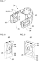
- FIGS. 8 to 10 show an exemplary assembly 48 in which the cover 26 and the optical filter 32 can be accommodated. It is possible that the assembly 48 can be mounted on the first outer leg 36 of the base frame 34.
- the assembly 48 has a frame 50.
- the cover 26 is accommodated in the frame 50.
- the cover 26 has a first disk 52 and a second disk 54.
- the disk 52 is preferably circular.
- the disk 52 is opaque.
- the disk 52 is rotatably mounted in the frame 50.
- the disk 52 has an eccentrically arranged through hole 56.
- the second disk 54 is rotatably mounted in the through hole 56.
- the disk 54 is preferably circular.
- the disk 54 is opaque.
- the disk 54 has an eccentrically arranged through hole 58.
- the light beam can pass through the cover 26 through the through hole 58.
- the optical filter 32 can be arranged in the through hole 58 if desired (see Figure 10 ).
- the optical filter 32 can be secured in the through hole 58 by means of a locking ring 60. It is possible that the cover 26 with the two disks 52, 54 is used in other configurations (see Figures 1 to 4 ) which the assembly 48 does not otherwise have.
- the frame 50 may further comprise a receptacle 62 for the sensor 20 (not shown) and/or a receptacle 64 for the sensor protective screen 30 (not shown).
- the Figure 11 shows a Figures 5 to 7 modified embodiment.
- the light source 18' has an elongated body whose longitudinal axis runs substantially parallel to a longitudinal axis of the second outer leg 38.
- the light source 18' can be arranged at least partially on the middle leg 40 and/or the second outer leg 38.
- a deflection mirror 66 deflects the light beam from the light source 18' to the container holder 14, e.g. in a range between 30° and 150°, particularly preferably by around 90°.
- the deflection mirror 66 can be arranged on the second outer leg 38.
Landscapes
- Physics & Mathematics (AREA)
- Electromagnetism (AREA)
- Thermal Sciences (AREA)
- Fluid Mechanics (AREA)
- General Physics & Mathematics (AREA)
- Filling Of Jars Or Cans And Processes For Cleaning And Sealing Jars (AREA)
- Basic Packing Technique (AREA)
Claims (15)
- Dispositif (10) pour la surveillance du niveau de remplissage de récipients (12) pour une installation de traitement de récipients, dans lequel le dispositif (10) présente :un réceptacle pour récipient (14) destiné à recevoir un récipient (12) ;un appareil de remplissage (16) qui est disposé pour remplir d'un liquide un récipient (12) reçu dans le réceptacle pour récipient (14) ;une source lumineuse (18) permettant d'émettre un faisceau lumineux destiné à passer à travers un récipient (12) reçu dans le réceptacle pour récipient (14) ; etun capteur photosensible (20) qui est disposé pour recevoir le faisceau lumineux uniquement lorsque le liquide dans le récipient (12) possède un niveau de remplissage auquel le faisceau lumineux a été réfracté par le liquide dans le récipient (12) lors du passage dudit faisceau lumineux à travers le récipient (12),caractérisé en ce quela source lumineuse (18) et/ou le capteur photosensible (20) sont réglables, à savoir qu'ils peuvent pivoter en direction du réceptacle pour récipient (14) et à l'écart de celui-ci.
- Dispositif (10) selon la revendication 1, présentant en outre :
un élément de recouvrement (26) qui recouvre une section d'une surface de capteur photosensible du capteur photosensible (20), dans lequel, de préférence, l'élément de recouvrement (26) est réglable, de préférence est mobile, pour modifier la section recouverte. - Dispositif (10) selon la revendication 2, dans lequel l'élément de recouvrement (26) présente :un premier disque (52) qui est monté de manière à pouvoir tourner et présente un premier trou traversant (56) disposé de manière excentrique dans le premier disque (52) ; etun second disque (54) qui est monté de manière à pouvoir tourner dans le premier trou traversant (56) et présente un second trou traversant (58) disposé de manière excentrique dans le second disque (54) pour laisser passer le faisceau lumineux.
- Dispositif (10) selon l'une des revendications précédentes, présentant en outre :une vitre de protection de source lumineuse (28) qui est disposée entre la source lumineuse (18) et le réceptacle pour récipient (14) et qui est conçue pour protéger la source lumineuse (18) de morceaux de récipient en cas de bris du récipient dans le réceptacle pour récipient (14) ; et/ouune vitre de protection de capteur (30) qui est disposée entre le capteur photosensible (20) et le réceptacle pour récipient (14) et qui est conçue pour protéger le capteur photosensible (20) de morceaux de récipient en cas de bris du récipient dans le réceptacle pour récipient (14).
- Dispositif (10) selon l'une des revendications précédentes, dans lequel :la source lumineuse (18) est conçue pour émettre le faisceau lumineux dans une plage de longueurs d'onde prédéterminée ; etle dispositif (10) présente en outre un filtre optique (32), de préférence un filtre passe-bande et/ou un filtre de polarisation, qui est disposé entre le réceptacle pour récipient (14) et le capteur photosensible (20) et qui est configuré pour filtrer, de préférence partiellement ou totalement, une plage de longueurs d'onde de lumière en dehors de la plage de longueurs d'onde prédéterminée.
- Dispositif (10) selon la revendication 5 et au moins l'une des revendications 2 à 4, dans lequel :
le filtre optique (32) est intégré dans l'élément de recouvrement (26) et/ou dans la vitre de protection de capteur (30). - Dispositif (10) selon l'une des revendications précédentes, dans lequel :
la source lumineuse (18) et/ou le capteur photosensible (20) sont réglables en hauteur. - Dispositif (10) selon l'une des revendications précédentes, présentant en outre :
un châssis de base (34) qui supporte conjointement la source lumineuse (18) et le capteur photosensible (20). - Dispositif (10) selon la revendication 8, dans lequel :le châssis de base (34) présente une première branche extérieure (36), une seconde branche extérieure (38) et une branche centrale (40), dans lequel, de préférence, la première branche extérieure (36), la seconde branche extérieure (38) et la branche centrale (40) forment conjointement une forme en U ;dans lequel le capteur photosensible (20) est disposé sur la première branche extérieure (36) et la source lumineuse (18) est disposée sur au moins l'une parmi la seconde branche extérieure (38) et la branche centrale (40)
- Dispositif (10) selon la revendication 9, dans lequel :
la première branche extérieure (36) et/ou la seconde branche extérieure (38) sont reliées de manière mobile, de préférence de manière à pouvoir pivoter, à la branche centrale (40). - Dispositif (10) selon l'une des revendications précédentes, présentant en outre :
un miroir de déviation (66) qui est disposé pour dévier le faisceau lumineux émis par la source lumineuse (18) dans une direction vers le réceptacle pour récipient (14), de préférence dans une plage comprise entre 30° et 150°, de manière particulièrement préférée d'environ 90°. - Dispositif (10) selon la revendication 11 et l'une des revendications 9 ou 10, dans lequel :le miroir de déviation (66) est disposé sur la seconde branche extérieure (38) ; etla source lumineuse (18) présente un corps allongé dont l'axe longitudinal s'étend sensiblement parallèlement à un axe longitudinal de la seconde branche extérieure (38), et/ou la source lumineuse (18) est disposée au moins partiellement sur la branche centrale (40).
- Dispositif (10) selon l'une des revendications précédentes, comportant au moins l'une des caractéristiques suivantes :le capteur photosensible (20) et la source lumineuse (18) sont disposés sensiblement à la même hauteur ;le capteur photosensible (20) et la source lumineuse (18) sont disposés sur des côtés opposés l'un à l'autre du réceptacle pour récipient (14) ;le dispositif (10) présente en outre une unité de commande (24) qui est configurée pour arrêter un remplissage du récipient (12) au moyen de l'appareil de remplissage (16) lorsque l'unité de commande (24) reçoit en provenance du capteur photosensible (20) un signal qui indique que le faisceau lumineux a été reçu par le capteur photosensible (20) ; etle dispositif (10) est compris dans un carrousel de remplissage permettant de remplir des récipients (12).
- Procédé pour la surveillance du niveau de remplissage de récipients (12) pour une installation de traitement de récipients au moyen d'un dispositif (10) selon l'une des revendications précédentes, dans lequel le procédé présente :le remplissage d'un récipient (12) d'un liquide ;l'émission d'un faisceau lumineux qui passe à travers le récipient (12) pendant le remplissage ;la réception du faisceau lumineux émis au moyen d'un capteur photosensible (20) uniquement lorsque le liquide dans le récipient (12) possède un niveau de remplissage auquel le faisceau lumineux émis a été réfracté par le liquide dans le récipient (12) lors du passage dudit faisceau lumineux à travers le récipient (12), pendant le remplissage ; etl'arrêt du remplissage lorsque le faisceau lumineux émis a été reçu.
- Procédé selon la revendication 14, dans lequel le procédé présente au moins l'une des caractéristiques suivantes :recouvrement d'une section d'une surface de capteur photosensible du capteur photosensible (20), et de préférence modification de la section recouverte ;protection du capteur photosensible (20) contre des morceaux de récipient en cas de bris de récipient du récipient (12) ;filtrage de la lumière incidente sur le capteur photosensible (20), dans lequel des plages de longueurs d'onde de lumière, lesquelles sont en dehors d'une plage de longueurs d'onde du faisceau lumineux émis, sont filtrées, de préférence partiellement ou complètement ; etdéviation du faisceau lumineux émis au moyen d'un miroir de déviation (66) avant qu'il ne passe à travers le récipient (12).
Applications Claiming Priority (1)
| Application Number | Priority Date | Filing Date | Title |
|---|---|---|---|
| DE102020131355.1A DE102020131355A1 (de) | 2020-11-26 | 2020-11-26 | Vorrichtung und Verfahren zur Füllstandüberwachung |
Publications (3)
| Publication Number | Publication Date |
|---|---|
| EP4006501A1 EP4006501A1 (fr) | 2022-06-01 |
| EP4006501C0 EP4006501C0 (fr) | 2024-10-30 |
| EP4006501B1 true EP4006501B1 (fr) | 2024-10-30 |
Family
ID=78528678
Family Applications (1)
| Application Number | Title | Priority Date | Filing Date |
|---|---|---|---|
| EP21206397.8A Active EP4006501B1 (fr) | 2020-11-26 | 2021-11-04 | Dispositif et procédé de surveillance de niveau de remplissage |
Country Status (3)
| Country | Link |
|---|---|
| EP (1) | EP4006501B1 (fr) |
| CN (1) | CN114543936A (fr) |
| DE (1) | DE102020131355A1 (fr) |
Families Citing this family (2)
| Publication number | Priority date | Publication date | Assignee | Title |
|---|---|---|---|---|
| DE102023115751A1 (de) * | 2023-06-15 | 2024-12-19 | Krones Aktiengesellschaft | Vorrichtung zum Befüllen eines Behälters mit einem Füllprodukt |
| DE202024100461U1 (de) * | 2024-01-31 | 2025-05-02 | Leuze Electronic Gmbh + Co. Kg | Optischer Sensor |
Citations (1)
| Publication number | Priority date | Publication date | Assignee | Title |
|---|---|---|---|---|
| WO2002084229A1 (fr) * | 2001-04-12 | 2002-10-24 | Sator Laser Gmbh | Dispositif et procede de surveillance du niveau de remplissage de contenants transparents mobiles |
Family Cites Families (15)
| Publication number | Priority date | Publication date | Assignee | Title |
|---|---|---|---|---|
| US3094213A (en) * | 1960-06-30 | 1963-06-18 | Industrial Automation Corp | Fill-height inspection device for fluid in bottles |
| BE757568A (fr) * | 1969-10-15 | 1971-04-15 | Barry Wehmiller Machinery Cy L | Machine a inspecter des bouteilles |
| JPS5484764A (en) | 1977-12-19 | 1979-07-05 | Fuji Electric Co Ltd | Liquid level inspector within vessel |
| DE3143860C2 (de) * | 1981-11-05 | 1986-06-05 | Brown, Boveri & Cie Ag, 6800 Mannheim | Anordnung zur Messung von Füllständen an Badspiegeln |
| DE4410515C2 (de) | 1994-03-28 | 1999-07-22 | Retec Elektronische Regeltechn | Kontrollvorrichtung für Füllstände |
| DE19800131C1 (de) * | 1998-01-03 | 1999-05-20 | Foerderung Angewandter Informa | Vorrichtung zur Bestimmung der Volumina von sich in Gefäßbatterien befindenden Flüssigkeiten |
| DE102004054859B4 (de) | 2004-11-12 | 2007-05-03 | Sensor- Data Instruments E.K. | Verfahren und Vorrichtung zur optischen Schaumkontrolle in Flaschenhälsen |
| JP4428569B2 (ja) | 2005-03-02 | 2010-03-10 | 三菱重工食品包装機械株式会社 | 回転式充填装置、液面レベル検出装置 |
| DE102006019518A1 (de) * | 2005-07-15 | 2007-01-18 | Robert Bosch Gmbh | Vorrichtung und Verfahren zum Befüllen von Behältnissen |
| TWI434027B (zh) * | 2010-04-21 | 2014-04-11 | 私立中原大學 | 偵測液體使用狀態裝置 |
| US9019367B2 (en) * | 2011-06-10 | 2015-04-28 | Wuerth Elektronik Ics Gmbh & Co. Kg | Method for dynamically detecting the fill level of a container, container therefor, and system for dynamically monitoring the fill level of a plurality of containers |
| DE102012203686B4 (de) * | 2012-03-08 | 2021-11-18 | Leica Biosystems Nussloch Gmbh | Eindeckautomat mit optischem Grenzfüllstandsmessgerät für eine Flüssigkeit |
| DE102013206543A1 (de) * | 2012-07-16 | 2014-01-16 | Robert Bosch Gmbh | Vorrichtung zum Befüllen von Behältnissen |
| DE102014118854A1 (de) | 2014-12-17 | 2016-06-23 | Endress + Hauser Conducta Gesellschaft für Mess- und Regeltechnik mbH + Co. KG | Vorrichtung zur Bestimmung einer die Flüssigkeitsmenge repräsentierenden Größe sowie deren Verwendung |
| DE102018133602A1 (de) | 2017-12-29 | 2019-07-04 | dEE dieEntwickler Elektronik GmbH | Kontrollvorrichtung zum Bestimmen eines Füllstandes |
-
2020
- 2020-11-26 DE DE102020131355.1A patent/DE102020131355A1/de active Pending
-
2021
- 2021-11-04 EP EP21206397.8A patent/EP4006501B1/fr active Active
- 2021-11-25 CN CN202111411939.3A patent/CN114543936A/zh active Pending
Patent Citations (1)
| Publication number | Priority date | Publication date | Assignee | Title |
|---|---|---|---|---|
| WO2002084229A1 (fr) * | 2001-04-12 | 2002-10-24 | Sator Laser Gmbh | Dispositif et procede de surveillance du niveau de remplissage de contenants transparents mobiles |
Also Published As
| Publication number | Publication date |
|---|---|
| EP4006501A1 (fr) | 2022-06-01 |
| CN114543936A (zh) | 2022-05-27 |
| EP4006501C0 (fr) | 2024-10-30 |
| DE102020131355A1 (de) | 2022-06-02 |
Similar Documents
| Publication | Publication Date | Title |
|---|---|---|
| EP4006501B1 (fr) | Dispositif et procédé de surveillance de niveau de remplissage | |
| EP2379439B2 (fr) | Procédé ainsi que dispositif d'inspection pour vérifier des récipients | |
| EP1130384B1 (fr) | Machine de contrôle | |
| DE2928844C2 (fr) | ||
| EP2369328B1 (fr) | Procédé et dispositif pour examiner des impuretés dans des récipients rempli | |
| EP0593726A1 (fr) | Machine d'inspection en continu de recipients. | |
| WO2014029470A1 (fr) | Inspection de l'intérieur de récipients par le bas à travers le fond | |
| DE69424236T2 (de) | Prüfung von durchsichtigen Behältern | |
| DE60224623T2 (de) | Wanddickenmessung eines transparenten Behälters mit einem Lichtfächer | |
| EP2986973B1 (fr) | Récipient d'essai servant à tester des machines de contrôle | |
| DE2802107A1 (de) | Verfahren zum optischen abtasten von fehlern in transparenten gegenstaenden, insbesondere glaesern, und vorrichtung zur durchfuehrung des verfahrens | |
| CH683288A5 (de) | Verfahren und Vorrichtung zur Beaufschlagung bewegter Gebinde mit einem Laserstrahl. | |
| DE102007054657A1 (de) | Optische Erfassungseinrichtung, insbesondere zur Inspektion von Flaschen, sowie entsprechendes Visualisierungsverfahren | |
| EP3110701B1 (fr) | Dispositif d'inspection de recipients | |
| DE69935034T2 (de) | Leseverfahren und -vorrichtung für reliefmarkierungen in einem durchsichtigen oder durchscheinenden behälter | |
| DE19920007C1 (de) | Vorrichtung zur Inspektion von Dichtflächen an Flaschen | |
| EP3239697A1 (fr) | Procede et dispositif de detection de corps etrangers dans des recipients | |
| WO2009115169A1 (fr) | Système de transport de bouteilles, et dispositif de traitement de bouteilles | |
| EP2720036B1 (fr) | Dispositif de contrôle de produits | |
| DE3523975A1 (de) | Verfahren zur opto-elektronischen inspektion von flaschen | |
| DE2100729C3 (de) | Vorrichtung zum Prüfen transparenter Behälter auf Blasen oder Fehler | |
| DE102004054859B4 (de) | Verfahren und Vorrichtung zur optischen Schaumkontrolle in Flaschenhälsen | |
| DE69725368T2 (de) | Verfahren und Vorrichtung zum Detektieren von Glas-Splittern | |
| DE3320476C1 (de) | Vorrichtung zum Prüfen von Hohlgläsern, insbesondere Flaschen, auf Schadstellen im Mündungsbereich | |
| DE19726967C1 (de) | Vorrichtung zum optischen Abbilden der umlaufenden Seitenfläche eines Gegenstandes, insbesondere eines 0-Rings |
Legal Events
| Date | Code | Title | Description |
|---|---|---|---|
| PUAI | Public reference made under article 153(3) epc to a published international application that has entered the european phase |
Free format text: ORIGINAL CODE: 0009012 |
|
| STAA | Information on the status of an ep patent application or granted ep patent |
Free format text: STATUS: THE APPLICATION HAS BEEN PUBLISHED |
|
| AK | Designated contracting states |
Kind code of ref document: A1 Designated state(s): AL AT BE BG CH CY CZ DE DK EE ES FI FR GB GR HR HU IE IS IT LI LT LU LV MC MK MT NL NO PL PT RO RS SE SI SK SM TR |
|
| STAA | Information on the status of an ep patent application or granted ep patent |
Free format text: STATUS: REQUEST FOR EXAMINATION WAS MADE |
|
| 17P | Request for examination filed |
Effective date: 20221130 |
|
| RBV | Designated contracting states (corrected) |
Designated state(s): AL AT BE BG CH CY CZ DE DK EE ES FI FR GB GR HR HU IE IS IT LI LT LU LV MC MK MT NL NO PL PT RO RS SE SI SK SM TR |
|
| STAA | Information on the status of an ep patent application or granted ep patent |
Free format text: STATUS: EXAMINATION IS IN PROGRESS |
|
| 17Q | First examination report despatched |
Effective date: 20230207 |
|
| P01 | Opt-out of the competence of the unified patent court (upc) registered |
Effective date: 20230523 |
|
| GRAP | Despatch of communication of intention to grant a patent |
Free format text: ORIGINAL CODE: EPIDOSNIGR1 |
|
| STAA | Information on the status of an ep patent application or granted ep patent |
Free format text: STATUS: GRANT OF PATENT IS INTENDED |
|
| INTG | Intention to grant announced |
Effective date: 20240621 |
|
| GRAS | Grant fee paid |
Free format text: ORIGINAL CODE: EPIDOSNIGR3 |
|
| GRAA | (expected) grant |
Free format text: ORIGINAL CODE: 0009210 |
|
| STAA | Information on the status of an ep patent application or granted ep patent |
Free format text: STATUS: THE PATENT HAS BEEN GRANTED |
|
| AK | Designated contracting states |
Kind code of ref document: B1 Designated state(s): AL AT BE BG CH CY CZ DE DK EE ES FI FR GB GR HR HU IE IS IT LI LT LU LV MC MK MT NL NO PL PT RO RS SE SI SK SM TR |
|
| REG | Reference to a national code |
Ref country code: GB Ref legal event code: FG4D Free format text: NOT ENGLISH |
|
| REG | Reference to a national code |
Ref country code: CH Ref legal event code: EP |
|
| REG | Reference to a national code |
Ref country code: IE Ref legal event code: FG4D Free format text: LANGUAGE OF EP DOCUMENT: GERMAN |
|
| REG | Reference to a national code |
Ref country code: DE Ref legal event code: R096 Ref document number: 502021005625 Country of ref document: DE |
|
| U01 | Request for unitary effect filed |
Effective date: 20241106 |
|
| P04 | Withdrawal of opt-out of the competence of the unified patent court (upc) registered |
Free format text: CASE NUMBER: APP_60691/2024 Effective date: 20241111 |
|
| U07 | Unitary effect registered |
Designated state(s): AT BE BG DE DK EE FI FR IT LT LU LV MT NL PT RO SE SI Effective date: 20241114 |
|
| U20 | Renewal fee for the european patent with unitary effect paid |
Year of fee payment: 4 Effective date: 20241203 |
|
| PG25 | Lapsed in a contracting state [announced via postgrant information from national office to epo] |
Ref country code: IS Free format text: LAPSE BECAUSE OF FAILURE TO SUBMIT A TRANSLATION OF THE DESCRIPTION OR TO PAY THE FEE WITHIN THE PRESCRIBED TIME-LIMIT Effective date: 20250228 Ref country code: HR Free format text: LAPSE BECAUSE OF FAILURE TO SUBMIT A TRANSLATION OF THE DESCRIPTION OR TO PAY THE FEE WITHIN THE PRESCRIBED TIME-LIMIT Effective date: 20241030 |
|
| PG25 | Lapsed in a contracting state [announced via postgrant information from national office to epo] |
Ref country code: ES Free format text: LAPSE BECAUSE OF FAILURE TO SUBMIT A TRANSLATION OF THE DESCRIPTION OR TO PAY THE FEE WITHIN THE PRESCRIBED TIME-LIMIT Effective date: 20241030 |
|
| PG25 | Lapsed in a contracting state [announced via postgrant information from national office to epo] |
Ref country code: NO Free format text: LAPSE BECAUSE OF FAILURE TO SUBMIT A TRANSLATION OF THE DESCRIPTION OR TO PAY THE FEE WITHIN THE PRESCRIBED TIME-LIMIT Effective date: 20250130 |
|
| PG25 | Lapsed in a contracting state [announced via postgrant information from national office to epo] |
Ref country code: GR Free format text: LAPSE BECAUSE OF FAILURE TO SUBMIT A TRANSLATION OF THE DESCRIPTION OR TO PAY THE FEE WITHIN THE PRESCRIBED TIME-LIMIT Effective date: 20250131 |
|
| PG25 | Lapsed in a contracting state [announced via postgrant information from national office to epo] |
Ref country code: PL Free format text: LAPSE BECAUSE OF FAILURE TO SUBMIT A TRANSLATION OF THE DESCRIPTION OR TO PAY THE FEE WITHIN THE PRESCRIBED TIME-LIMIT Effective date: 20241030 |
|
| PG25 | Lapsed in a contracting state [announced via postgrant information from national office to epo] |
Ref country code: RS Free format text: LAPSE BECAUSE OF FAILURE TO SUBMIT A TRANSLATION OF THE DESCRIPTION OR TO PAY THE FEE WITHIN THE PRESCRIBED TIME-LIMIT Effective date: 20250130 |
|
| REG | Reference to a national code |
Ref country code: CH Ref legal event code: PL |
|
| PG25 | Lapsed in a contracting state [announced via postgrant information from national office to epo] |
Ref country code: SM Free format text: LAPSE BECAUSE OF FAILURE TO SUBMIT A TRANSLATION OF THE DESCRIPTION OR TO PAY THE FEE WITHIN THE PRESCRIBED TIME-LIMIT Effective date: 20241030 |
|
| PG25 | Lapsed in a contracting state [announced via postgrant information from national office to epo] |
Ref country code: MC Free format text: LAPSE BECAUSE OF FAILURE TO SUBMIT A TRANSLATION OF THE DESCRIPTION OR TO PAY THE FEE WITHIN THE PRESCRIBED TIME-LIMIT Effective date: 20241030 |
|
| REG | Reference to a national code |
Ref country code: CH Ref legal event code: PL |
|
| PG25 | Lapsed in a contracting state [announced via postgrant information from national office to epo] |
Ref country code: CH Free format text: LAPSE BECAUSE OF NON-PAYMENT OF DUE FEES Effective date: 20241130 |
|
| PG25 | Lapsed in a contracting state [announced via postgrant information from national office to epo] |
Ref country code: SK Free format text: LAPSE BECAUSE OF FAILURE TO SUBMIT A TRANSLATION OF THE DESCRIPTION OR TO PAY THE FEE WITHIN THE PRESCRIBED TIME-LIMIT Effective date: 20241030 |
|
| PG25 | Lapsed in a contracting state [announced via postgrant information from national office to epo] |
Ref country code: CZ Free format text: LAPSE BECAUSE OF FAILURE TO SUBMIT A TRANSLATION OF THE DESCRIPTION OR TO PAY THE FEE WITHIN THE PRESCRIBED TIME-LIMIT Effective date: 20241030 |
|
| PLBE | No opposition filed within time limit |
Free format text: ORIGINAL CODE: 0009261 |
|
| STAA | Information on the status of an ep patent application or granted ep patent |
Free format text: STATUS: NO OPPOSITION FILED WITHIN TIME LIMIT |
|
| 26N | No opposition filed |
Effective date: 20250731 |
|
| PG25 | Lapsed in a contracting state [announced via postgrant information from national office to epo] |
Ref country code: IE Free format text: LAPSE BECAUSE OF NON-PAYMENT OF DUE FEES Effective date: 20241104 |
|
| U20 | Renewal fee for the european patent with unitary effect paid |
Year of fee payment: 5 Effective date: 20251008 |
|
| PG25 | Lapsed in a contracting state [announced via postgrant information from national office to epo] |
Ref country code: HU Free format text: LAPSE BECAUSE OF FAILURE TO SUBMIT A TRANSLATION OF THE DESCRIPTION OR TO PAY THE FEE WITHIN THE PRESCRIBED TIME-LIMIT; INVALID AB INITIO Effective date: 20211104 |
|
| PG25 | Lapsed in a contracting state [announced via postgrant information from national office to epo] |
Ref country code: CY Free format text: LAPSE BECAUSE OF FAILURE TO SUBMIT A TRANSLATION OF THE DESCRIPTION OR TO PAY THE FEE WITHIN THE PRESCRIBED TIME-LIMIT; INVALID AB INITIO Effective date: 20211104 |