EP4006559B1 - Procédé, système et produit-programme informatique permettant de déterminer un potentiel de déplacement de charge d'un consommateur électrique - Google Patents
Procédé, système et produit-programme informatique permettant de déterminer un potentiel de déplacement de charge d'un consommateur électrique Download PDFInfo
- Publication number
- EP4006559B1 EP4006559B1 EP21210854.2A EP21210854A EP4006559B1 EP 4006559 B1 EP4006559 B1 EP 4006559B1 EP 21210854 A EP21210854 A EP 21210854A EP 4006559 B1 EP4006559 B1 EP 4006559B1
- Authority
- EP
- European Patent Office
- Prior art keywords
- load
- electrical
- electrical load
- energy consumption
- function
- Prior art date
- Legal status (The legal status is an assumption and is not a legal conclusion. Google has not performed a legal analysis and makes no representation as to the accuracy of the status listed.)
- Active
Links
Images




Classifications
-
- G—PHYSICS
- G01—MEASURING; TESTING
- G01R—MEASURING ELECTRIC VARIABLES; MEASURING MAGNETIC VARIABLES
- G01R19/00—Arrangements for measuring currents or voltages or for indicating presence or sign thereof
- G01R19/25—Arrangements for measuring currents or voltages or for indicating presence or sign thereof using digital measurement techniques
- G01R19/2513—Arrangements for monitoring electric power systems, e.g. power lines or loads; Logging
-
- F—MECHANICAL ENGINEERING; LIGHTING; HEATING; WEAPONS; BLASTING
- F24—HEATING; RANGES; VENTILATING
- F24H—FLUID HEATERS, e.g. WATER OR AIR HEATERS, HAVING HEAT-GENERATING MEANS, e.g. HEAT PUMPS, IN GENERAL
- F24H15/00—Control of fluid heaters
- F24H15/10—Control of fluid heaters characterised by the purpose of the control
- F24H15/16—Reducing cost using the price of energy, e.g. choosing or switching between different energy sources
- F24H15/164—Reducing cost using the price of energy, e.g. choosing or switching between different energy sources where the price of the electric supply changes with time
-
- F—MECHANICAL ENGINEERING; LIGHTING; HEATING; WEAPONS; BLASTING
- F24—HEATING; RANGES; VENTILATING
- F24H—FLUID HEATERS, e.g. WATER OR AIR HEATERS, HAVING HEAT-GENERATING MEANS, e.g. HEAT PUMPS, IN GENERAL
- F24H15/00—Control of fluid heaters
- F24H15/10—Control of fluid heaters characterised by the purpose of the control
- F24H15/168—Reducing the electric power demand peak
-
- F—MECHANICAL ENGINEERING; LIGHTING; HEATING; WEAPONS; BLASTING
- F24—HEATING; RANGES; VENTILATING
- F24H—FLUID HEATERS, e.g. WATER OR AIR HEATERS, HAVING HEAT-GENERATING MEANS, e.g. HEAT PUMPS, IN GENERAL
- F24H15/00—Control of fluid heaters
- F24H15/10—Control of fluid heaters characterised by the purpose of the control
- F24H15/172—Scheduling based on user demand, e.g. determining starting point of heating
-
- F—MECHANICAL ENGINEERING; LIGHTING; HEATING; WEAPONS; BLASTING
- F24—HEATING; RANGES; VENTILATING
- F24H—FLUID HEATERS, e.g. WATER OR AIR HEATERS, HAVING HEAT-GENERATING MEANS, e.g. HEAT PUMPS, IN GENERAL
- F24H15/00—Control of fluid heaters
- F24H15/20—Control of fluid heaters characterised by control inputs
- F24H15/269—Time, e.g. hour or date
-
- H—ELECTRICITY
- H02—GENERATION; CONVERSION OR DISTRIBUTION OF ELECTRIC POWER
- H02J—ELECTRIC POWER NETWORKS; CIRCUIT ARRANGEMENTS OR SYSTEMS FOR SUPPLYING OR DISTRIBUTING ELECTRIC POWER; SYSTEMS FOR STORING ELECTRIC ENERGY
- H02J2105/00—Networks for supplying or distributing electric power characterised by their spatial reach or by the load
- H02J2105/50—Networks for supplying or distributing electric power characterised by their spatial reach or by the load for selectively controlling the operation of the loads
- H02J2105/51—Networks for supplying or distributing electric power characterised by their spatial reach or by the load for selectively controlling the operation of the loads according to a condition being electrical
-
- H—ELECTRICITY
- H02—GENERATION; CONVERSION OR DISTRIBUTION OF ELECTRIC POWER
- H02J—ELECTRIC POWER NETWORKS; CIRCUIT ARRANGEMENTS OR SYSTEMS FOR SUPPLYING OR DISTRIBUTING ELECTRIC POWER; SYSTEMS FOR STORING ELECTRIC ENERGY
- H02J2105/00—Networks for supplying or distributing electric power characterised by their spatial reach or by the load
- H02J2105/50—Networks for supplying or distributing electric power characterised by their spatial reach or by the load for selectively controlling the operation of the loads
- H02J2105/54—Networks for supplying or distributing electric power characterised by their spatial reach or by the load for selectively controlling the operation of the loads according to a non-electrical condition, e.g. temperature
-
- H—ELECTRICITY
- H02—GENERATION; CONVERSION OR DISTRIBUTION OF ELECTRIC POWER
- H02J—ELECTRIC POWER NETWORKS; CIRCUIT ARRANGEMENTS OR SYSTEMS FOR SUPPLYING OR DISTRIBUTING ELECTRIC POWER; SYSTEMS FOR STORING ELECTRIC ENERGY
- H02J3/00—Circuit arrangements for AC mains or AC distribution networks
- H02J3/12—Arrangements for adjusting voltage in AC networks by changing a characteristic of the network load
- H02J3/14—Arrangements for adjusting voltage in AC networks by changing a characteristic of the network load by switching loads on to, or off from, the networks, e.g. progressively balanced loading
-
- Y—GENERAL TAGGING OF NEW TECHNOLOGICAL DEVELOPMENTS; GENERAL TAGGING OF CROSS-SECTIONAL TECHNOLOGIES SPANNING OVER SEVERAL SECTIONS OF THE IPC; TECHNICAL SUBJECTS COVERED BY FORMER USPC CROSS-REFERENCE ART COLLECTIONS [XRACs] AND DIGESTS
- Y02—TECHNOLOGIES OR APPLICATIONS FOR MITIGATION OR ADAPTATION AGAINST CLIMATE CHANGE
- Y02B—CLIMATE CHANGE MITIGATION TECHNOLOGIES RELATED TO BUILDINGS, e.g. HOUSING, HOUSE APPLIANCES OR RELATED END-USER APPLICATIONS
- Y02B70/00—Technologies for an efficient end-user side electric power management and consumption
- Y02B70/30—Systems integrating technologies related to power network operation and communication or information technologies for improving the carbon footprint of the management of residential or tertiary loads, i.e. smart grids as climate change mitigation technology in the buildings sector, including also the last stages of power distribution and the control, monitoring or operating management systems at local level
-
- Y—GENERAL TAGGING OF NEW TECHNOLOGICAL DEVELOPMENTS; GENERAL TAGGING OF CROSS-SECTIONAL TECHNOLOGIES SPANNING OVER SEVERAL SECTIONS OF THE IPC; TECHNICAL SUBJECTS COVERED BY FORMER USPC CROSS-REFERENCE ART COLLECTIONS [XRACs] AND DIGESTS
- Y02—TECHNOLOGIES OR APPLICATIONS FOR MITIGATION OR ADAPTATION AGAINST CLIMATE CHANGE
- Y02B—CLIMATE CHANGE MITIGATION TECHNOLOGIES RELATED TO BUILDINGS, e.g. HOUSING, HOUSE APPLIANCES OR RELATED END-USER APPLICATIONS
- Y02B70/00—Technologies for an efficient end-user side electric power management and consumption
- Y02B70/30—Systems integrating technologies related to power network operation and communication or information technologies for improving the carbon footprint of the management of residential or tertiary loads, i.e. smart grids as climate change mitigation technology in the buildings sector, including also the last stages of power distribution and the control, monitoring or operating management systems at local level
- Y02B70/3225—Demand response systems, e.g. load shedding, peak shaving
-
- Y—GENERAL TAGGING OF NEW TECHNOLOGICAL DEVELOPMENTS; GENERAL TAGGING OF CROSS-SECTIONAL TECHNOLOGIES SPANNING OVER SEVERAL SECTIONS OF THE IPC; TECHNICAL SUBJECTS COVERED BY FORMER USPC CROSS-REFERENCE ART COLLECTIONS [XRACs] AND DIGESTS
- Y04—INFORMATION OR COMMUNICATION TECHNOLOGIES HAVING AN IMPACT ON OTHER TECHNOLOGY AREAS
- Y04S—SYSTEMS INTEGRATING TECHNOLOGIES RELATED TO POWER NETWORK OPERATION, COMMUNICATION OR INFORMATION TECHNOLOGIES FOR IMPROVING THE ELECTRICAL POWER GENERATION, TRANSMISSION, DISTRIBUTION, MANAGEMENT OR USAGE, i.e. SMART GRIDS
- Y04S20/00—Management or operation of end-user stationary applications or the last stages of power distribution; Controlling, monitoring or operating thereof
- Y04S20/20—End-user application control systems
- Y04S20/222—Demand response systems, e.g. load shedding, peak shaving
-
- Y—GENERAL TAGGING OF NEW TECHNOLOGICAL DEVELOPMENTS; GENERAL TAGGING OF CROSS-SECTIONAL TECHNOLOGIES SPANNING OVER SEVERAL SECTIONS OF THE IPC; TECHNICAL SUBJECTS COVERED BY FORMER USPC CROSS-REFERENCE ART COLLECTIONS [XRACs] AND DIGESTS
- Y04—INFORMATION OR COMMUNICATION TECHNOLOGIES HAVING AN IMPACT ON OTHER TECHNOLOGY AREAS
- Y04S—SYSTEMS INTEGRATING TECHNOLOGIES RELATED TO POWER NETWORK OPERATION, COMMUNICATION OR INFORMATION TECHNOLOGIES FOR IMPROVING THE ELECTRICAL POWER GENERATION, TRANSMISSION, DISTRIBUTION, MANAGEMENT OR USAGE, i.e. SMART GRIDS
- Y04S20/00—Management or operation of end-user stationary applications or the last stages of power distribution; Controlling, monitoring or operating thereof
- Y04S20/20—End-user application control systems
- Y04S20/242—Home appliances
- Y04S20/244—Home appliances the home appliances being or involving heating ventilating and air conditioning [HVAC] units
Definitions
- One goal is therefore to link at least part of the energy demand to current energy resources.
- the EP 2 822 134 A1 shows a management device that manages a plurality of heat pump systems and that adjusts a total amount of energy consumed by the heat pump systems to a target value.
- the management device includes a request transmission unit that transmits values for a desired energy consumption to each of the heat pump systems, an information reception unit that receives current energy consumption values from each of the heat pumps, a database for storing a response behavior of the energy consumers of each of the heat pump systems in connection with the values of the desired energy consumption, and a learning unit that learns the response behavior and reflects learning results based on the data stored in the database.
- the DE 10 2017 220 414 A1 shows a method for operating a heat storage system, wherein an electrical load associated with the operation of the heat pump is shifted in time and wherein the load shift is controlled by the local energy management, wherein a power consumption of the heat pump is controlled such that this power consumption corresponds to a default value for the electrical power consumption specified by the local energy management is present, provided that the heat-side requirements of the heat storage system allow this.
- the DE 10 2009 010 117 A1 shows a method for equalizing the reference power of electrical energy for an energy consumer who has several electrical energy-consuming devices that are assigned to groups of different priorities, wherein in a first step an uncontrolled consumption of power is determined over a definable period of time with calendar reference and wherein in a second step an average value is formed with this uncontrolled consumption of power, which is used as a specification for a target value during a similar subsequent period of time, wherein the devices are switched according to their priority in order not to exceed the target value with the current power.
- both types of control signals can be used for short-term reserves with a delivery time of 15 minutes, but differ in the possible shapes of the resulting load curves and in the response time of the controlled system.
- a model for the synergistic behavior of an ensemble of refrigerators that respond to control signals is shown. This mathematical model predicts the power demand of an ensemble of controlled devices.
- the DE 10 2013 214 996 A1 shows a device for load shifting in intelligent power distribution networks, in which the consumption of electrical energy takes place at the most favorable time possible, i.e. when there is a lot of energy in the network or when a variable electricity price is low. This is achieved by making a forecast for the course of the electricity price over a next time interval receivable in a device and using this to generate current binary values for Switching recommendations can be determined for a majority of devices, whereby the switching recommendations are only classified according to the parameters "switching interval", "on probability” and "time window considered”.
- the DE 10 2017 217 055 A1 shows an energy flow control device for controlling a load shift of a plurality of electrical energy consumers connected to a network connection point.
- the energy flow control device is designed to compare relative efficiencies of the consumers with one another and to control individual load shifts of the consumers depending on the relative efficiencies, wherein each relative efficiency is defined as an efficiency of the consumer standardized to a current efficiency of the consumer, with which the consumer would currently work with an electrical load increased for the load shift.
- One aspect of the application is a method for determining a load shift potential of an electrical consumer.
- the electrical consumer can be set up in particular to generate heat and/or cold in one or more heating and/or cooling circuits.
- the electrical consumer can be, for example, a heat pump, an electric radiator, an electrically heated hot water tank, a cooling unit, etc.
- a load shift potential can be a measure of the extent to which an adjustment of an electrical load of the electrical consumer, in particular with regard to a time of energy consumption of the electrical consumer and/or with regard to an amount of energy at a time in a time range.
- a load shifting potential can comprise one or more variables for this purpose.
- An adjustment (load shifting) can then advantageously be carried out with regard to the time of energy consumption and/or with regard to the electrical power of the electrical energy consumption within a predetermined time interval of the electrical consumer in accordance with the load shifting potential, so that heat requirements or cold requirements for the electrical consumer can be met/served by the electrical consumer without or with only minor restrictions.
- a first step of the method can be the recording of an electrical energy consumption of the electrical consumer as a reference energy consumption of the electrical consumer.
- the recording of the electrical energy consumption can be carried out, for example, by means of a unit for recording an electrical energy consumption.
- the recording of the electrical energy consumption can include recording an energy consumption as a function of time, recording an electrical power of the electrical energy consumption as a function of time, etc.
- detecting the electrical energy consumption may include detecting a start time of a load operation of the electrical consumer, an end time of the load operation of the electrical consumer, and the electrical power of the electrical consumer during the load operation.
- a load operation may be an operating state of the electrical consumer with the aim of generating a predetermined heat or cold.
- a further step in the process can be to determine a load shifting potential of the electrical consumer depending on the recorded reference energy consumption of the electrical consumer. This has the advantage that a load shifting potential can be determined with little effort and a small number of sensors. A further advantage is that a meaningful load shifting potential can be determined with as little intrusion into people's privacy as possible, since no information about living space temperatures is required. In addition, this makes it particularly easy to retrofit a corresponding process to existing electrical consumers.
- a particularly advantageous method can comprise the additional step of determining a charging time constant of the electrical consumer as a function of the recorded reference energy consumption, wherein the load shift potential is determined as a function of the charging time constant of the electrical consumer and the charging time constant of the electrical consumer is determined as a function of a duration of one or more operating intervals of the electrical consumer.
- An operating interval can be an interval in which the electrical consumer is operated in a load mode.
- a loading time constant can be determined, for example, by calculating the average value over the duration of a large number of operating intervals and/or another mathematical function with the duration of the large number of operating intervals as the function argument.
- a particularly optimized method can include the additional step of determining a discharge time constant of the electrical consumer as a function of the recorded reference energy consumption, wherein the load shift potential is determined as a function of the discharge time constant of the electrical consumer and the discharge time constant of the electrical consumer is determined as a function of a length of one or more time periods between two consecutive operating intervals of the electrical consumer.
- a discharge time constant can be determined, for example, by forming the average over the length of a plurality of time periods between two consecutive operating intervals and/or another mathematical function with the length of a plurality of time periods between two consecutive operating intervals as the function argument.
- a particularly well thought-out method can include the additional step of determining an electrical load capacity of the electrical consumer depending on the recorded Reference energy consumption, wherein the load shift potential is determined as a function of the electrical load capacity of the electrical consumer and the electrical load capacity of the electrical consumer is determined as a function of an electrical power of the electrical consumer during the duration of one or more operating intervals of the electrical consumer and/or as a function of an energy consumption during the duration of one or more operating intervals of the electrical consumer.
- a load capacity can be determined, for example, by forming the average value over the electrical power or over the electrical energy consumption of the electrical consumer during the operating intervals and/or by means of another mathematical function with the electrical power or with the electrical energy consumption of the electrical consumer as the function argument.
- the load capacity, the charging time constant and/or the discharging time constant can be used to determine the extent to which a reduction or increase in the power of the electrical consumer is possible, so that the fulfillment of a heating or cooling requirement for the electrical consumer is not affected or is only slightly affected.
- a load shift potential can include values for the charging time constant, the discharging time constant and the load capacity. This has the advantage that a load shift potential can be determined particularly easily and a load shift potential can be transmitted with a small amount of data.
- the recording of the reference energy consumption can include the additional step of recording a total operating time of the electrical consumer within a first predetermined period of time.
- the method can include the additional step of recording a current operating time of the electrical consumer in a first current time interval. The load shift potential can then be determined depending on the total operating time of the electrical consumer and/or additionally depending on the current operating time of the electrical consumer.
- the length of the first predetermined time period can correspond to the length of the first current time interval.
- the load shift potential can additionally be determined depending on the length of the first predetermined time period and/or the length of the first current time interval. This can have the advantage that a particularly accurate estimate can be made regarding the duration of load operation of the electrical consumer in a predetermined time interval and thus a load shift potential can be determined particularly precisely and reliably.
- the recording of the reference energy consumption can include the additional step of recording a total energy consumption of the electrical consumer within a second predetermined time period.
- the method can include the additional step of recording a current energy consumption of the electrical consumer in a second current time interval.
- the load shifting potential can then be determined additionally depending on the total energy consumption of the electrical consumer and/or additionally depending on the current energy consumption of the electrical consumer.
- the length of the second predetermined time period corresponds to the length of the second current time interval.
- the length of the first predetermined time period can correspond to the length of the second predetermined time period and/or the length of the first current time interval can correspond to the length of the second current time interval.
- the load shift potential can additionally be determined as a function of the length of the second specified time period and the length of the second current time interval.
- a particularly reliable method can include the additional steps of specifying a target temperature for a heating and/or cooling circuit of the electrical consumer and/or detecting an actual temperature for a heating and/or cooling circuit of the electrical consumer, wherein the load shift potential is additionally determined as a function of the detected target temperature and/or additionally as a function of the detected actual temperature. This can increase the reliability of the determined load shift potential.
- a particularly advantageously developed method can include the additional steps of recording an outside temperature as a reference outside temperature in conjunction with recording the reference energy consumption of the electrical consumer and/or recording a current outside temperature, wherein the load shift potential is additionally determined as a function of the reference outside temperature and/or additionally as a function of the current outside temperature.
- the electrical consumer can be set up to provide heat and/or cold in several circuits, one circuit being a heating and/or cooling circuit.
- Detecting the reference energy consumption of the electrical consumer can include detecting the control of the several circuits and determining the load shifting potential can include determining the load shifting potential for at least one circuit of the several circuits.
- determining the load shifting potential of the electrical consumer can include determining the load shifting potential for a group of circuits, where the group may include one or more (or all) circuits of the electrical consumer.
- a particularly advanced method can include the additional step of determining an overcharge potential of the electrical consumer and/or the multiple circuits, wherein the load shift potential is additionally determined as a function of the overcharge potential determined.
- An overcharge potential can, for example, be a measure of the extent to which load operation of the electrical consumer can be extended beyond the actual duration of load operation or the extent to which the power and thus the energy consumption can be increased during load operation of the electrical consumer without causing damage or significantly reducing efficiency.
- the load shifting potential includes a reserve/buffer (the overload potential) and a maximum of the load shifting potential can be determined.
- a particularly large load shifting potential of the electrical consumer can have the advantage that the flexibility of the electrical consumer to compensate for both current peaks and load peaks in an energy network can be increased.
- a particularly flexible method can include the additional step of providing the load shifting potential so that the electrical consumer can be controlled depending on the load shifting potential of the electrical consumer, with the electrical consumer being controlled in particular by means of a demand response signal.
- This can have the advantage that the electrical consumer can be used particularly easily to compensate for current peaks and load peaks in a power grid.
- a particularly reliable method can include the additional step of outputting feedback from the electrical consumer as to whether and/or to what extent a load shift of the electrical consumer occurs when a control signal, in particular a demand response signal, is transmitted to the electrical consumer based on the load shift potential.
- This can have the advantage that a decision on a load shift of the electrical consumer lies with the electrical consumer or its operator and at the same time ensures that incorrect assumptions about a shift in the load of the electrical consumer are avoided.
- a particularly precise method can include the additional steps of recording a heating circuit temperature, cooling circuit temperature, a target temperature and/or building temperature as reference temperatures in conjunction with recording the reference energy consumption of the electrical consumer; and/or recording a current heating circuit temperature, a current cooling circuit temperature, a current target temperature and/or a current building temperature as current temperatures, wherein the load shifting potential is additionally determined as a function of the reference temperatures and/or additionally as a function of the current temperatures.
- a particularly advanced method can include the additional steps of recording environmental factors as reference environmental factors in conjunction with recording the reference energy consumption and/or recording current environmental factors, whereby the load shifting potential is also determined depending on the recorded reference environmental factors and/or the current environmental factors.
- Environmental factors can be, for example, vacation dates, holiday periods, weather data, public holidays, social events, major events, etc. This can have the advantage that a load shifting potential can be reliably determined even in the event of irregularities in people's behavior.
- reference data reference energy consumption, reference temperatures, etc.
- current data current energy consumption, current temperatures, etc.
- a time of data collection such as a day of the week, a season, a time of day, a working day, a holiday, etc.
- the load potential can be determined depending on at least one of these connections.
- a particularly adapted method can include the additional steps of determining a power grid that supplies the electrical consumer with electrical energy; and assigning the electrical consumer to a group of electrical consumers depending on the determined power grid.
- Determining a power grid can, for example, include determining a low-voltage grid, a medium-voltage grid, a high-voltage grid and/or an extra-high-voltage grid.
- the method can include a step of determining a power grid that supplies the electrical consumer with electrical energy, wherein the step of providing the load shifting potential comprises providing the result of determining the power grid.
- a particularly structured method may include an additional step of assigning the electrical consumer to a group of electrical consumers depending on the load shift potential. This may have the advantage that a large number of electrical consumers can be controlled in a simple manner depending on load or current peaks.
- One aspect of the application relates to a system for determining a load shift potential of an electrical consumer.
- the electrical consumer can advantageously be set up to generate heat and/or cold in one or more heating and/or cooling circuits.
- the system can comprise a recording unit for recording an electrical energy consumption of the electrical consumer as a reference energy consumption of the electrical consumer.
- the detection unit can preferably be set up to detect an electrical energy consumption of the electrical consumer as a reference energy consumption of the electrical consumer.
- the detection of an electrical energy consumption can, for example, comprise a detection of an electrical energy consumption as a function of time, an electrical power as a function of time, etc.
- the detection unit can, for example, comprise one or more digital circuits, in particular a programmable circuit and/or a microcontroller, etc.
- a control unit of the electrical energy consumer can comprise the detection unit.
- specifying a desired energy consumption to the electrical load in order to determine a demand behavior of the electrical load may be omitted.
- the system can comprise a determination unit for determining a load shift potential of the electrical consumer depending on the reference energy consumption of the electrical consumer.
- the determination unit can preferably be set up to determine a load shift potential of the electrical consumer depending on the reference energy consumption of the electrical consumer.
- the determination unit can comprise, for example, one or more analog and/or digital circuits, in particular computing units.
- the system has the advantage that a load shift potential of the electrical consumer can be determined particularly efficiently.
- a signal processing unit of the electrical consumer can comprise the detection unit and/or the determination unit. This has the advantage that the system can be provided in a particularly space-saving and integrated manner.
- the system can include a signal processing unit, wherein the signal processing unit comprises the detection unit and/or the determination unit.
- the signal processing unit comprises the detection unit and/or the determination unit.
- the system can comprise a communication unit that is set up to send an offer for a load shift depending on the determined load shift potential and/or to receive a request for a load shift.
- a communication unit that is set up to send an offer for a load shift depending on the determined load shift potential and/or to receive a request for a load shift.
- the detection unit can be set up to detect the electrical energy consumption of a plurality of electrical consumers and/or the determination unit can be set up to determine the load shift potential of a plurality of electrical consumers. This can have the advantage that the number of detection units and/or the number of determination units can be reduced and costs can thus be saved.
- system may be configured to perform a method as shown above.
- One aspect of the application relates to a computer program product for determining a load shift potential of an electrical consumer.
- the computer program product comprises instructions which, when the program is executed by a computer, cause the computer to carry out the steps of the method according to one of the Claims 1 to 15.
- a computer can be, for example, a microcontroller, a programmable logic circuit, a digital circuit, a semiconductor chip, a processor, etc. Instructions can be reproduced in one or more software programs, program codes, etc.
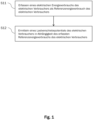
- Fig. 1 shows a schematic of a method according to an embodiment of the invention.
- the method can advantageously be set up to determine a load shift potential of an electrical consumer.
- the electrical consumer can be set up in particular to generate heat and/or cold in one or more heating and/or cooling circuits.
- the electrical consumer can in particular be a heat pump, a cooling unit, a heating rod, an electric hot water tank, etc.
- the detection can be carried out, for example, by means of a detection unit.
- an electrical energy consumption of the electrical consumer is recorded as a reference energy consumption of the electrical consumer.
- Recording the electrical energy consumption of the electrical consumer can in particular include recording the electrical energy consumption of the electrical consumer as a function of time.
- a load shifting potential of the electrical consumer is determined as a function of the recorded reference energy consumption of the electrical consumer, in particular by means of a determination unit.
- the load shifting potential of the electrical consumer can in particular contain information as to the extent to which a temporal shift of an energy consumption of the electrical consumer is possible.
- a load shifting potential can contain information as to the extent to which an energy consumption of the electrical consumer can be adjusted, in particular with regard to the power and/or the time.
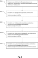
- Fig. 2 shows schematically a method according to an embodiment of the invention.
- the Fig. 2 The method shown is based on the Fig. 1
- the process shown in Fig. 2 The procedure shown differs from that in Fig. 1 shown method in that it can include steps S21, S22 and/or S23, each of which is optional.
- a charging time constant of the electrical consumer is determined as a function of the detected differential energy consumption.
- the load shift potential can be determined as a function of the charging time constant of the electrical consumer.
- a charging time constant of the electrical consumer can be determined as a function of a duration of one or more operating intervals of the electrical consumer.
- an operating interval refers to a load operation of the electrical consumer.
- an operating interval can refer to an operation of the electrical consumer that has the purpose of generating heat and/or cold.
- the charging time constant can be determined, for example, by means of a determination unit.
- a discharge time constant of the electrical consumer can be determined depending on the recorded reference energy consumption can be determined. Accordingly, the load shift potential can be determined in step S12 as a function of the discharge time constant of the electrical consumer.
- the discharge time constant of the electrical consumer can be determined as a function of the length of one or more time periods between two consecutive operating intervals of the electrical consumer. The discharge time constant can be determined, for example, by means of a determination unit.
- an electrical load capacity of the electrical consumer can be determined depending on the recorded reference energy consumption.
- the load shift potential can be determined in step S12 accordingly depending on the electrical load capacity of the electrical consumer.
- the electrical load capacity of the electrical consumer can be determined depending on an electrical power of the electrical consumer during the duration of one or more operating intervals of the electrical consumer and/or depending on an energy consumption during the duration of one or more operating intervals of the electrical consumer.
- the electrical load capacity can be determined, for example, by means of a determination unit.
- an electrical consumer can be represented in a simple manner using a model of a capacitance/capacitor.
- This has the advantage that a load shift potential can be determined particularly easily and efficiently.
- a load shift potential can be determined depending on a ratio between the charging time constant and the discharging time constant.
- Fig. 3 shows schematically a method according to an embodiment of the invention.
- the Fig. 3 The method shown is based on the Fig. 1 and differs in that it includes steps S31 and S32, each of which is optional.
- step S11 may include a step of detecting a total operating time of the electrical load within a first predetermined time period. Accordingly, the load shift potential can be determined in step S12 depending on the total operating time of the electrical consumer within the first predetermined time period.
- the method can include a step S31 of detecting a current operating time of the electrical consumer in a first current time interval, in particular by means of a detection unit.
- the determination of the load shift potential in step S12 can then additionally take place depending on the current operating time of the electrical consumer in the first current time interval.
- This estimate can in turn be used to determine the load shifting potential, so that the accuracy and reliability of the load shifting potential can be increased.
- This estimate can be further improved by recording a current operating time in a first current time interval.
- step S11 can include a step of recording a total energy consumption of the electrical consumer within a second predetermined time period. Accordingly, the load shifting potential can be determined in step S12 depending on the total energy consumption of the electrical consumer.
- the method can include an optional step S32 of recording a current energy consumption of the electrical consumer in a second current time interval, in particular by means of a recording unit. Accordingly, the load shifting potential can then be determined in step S12 depending on the current energy consumption of the electrical consumer. This can have the advantage that different operating modes of the electrical consumer, which can have different energy consumption, are taken into account. Consequently, the accuracy of the load shifting potential, in particular with regard to the energy consumption of the electrical consumer, can be improved.
- Fig. 4 shows schematically a method according to an embodiment of the invention.
- the Fig. 4 The method shown is based on the Fig. 1 shown method and differs from this in that it comprises steps S41 and/or S42, which are each optional.
- step S41 a target temperature for a heating and/or cooling circuit of the electrical consumer is specified.
- step S42 an actual temperature for a heating and/or cooling circuit of the electrical consumer is recorded.
- the load shift potential can then be determined depending on the specified target temperature and/or depending on the recorded actual temperature.
- a target temperature can advantageously be specified, for example, by means of a memory unit or a user interface.
- an actual temperature of a heating and/or cooling circuit can be recorded, for example, by means of temperature sensors.
- Fig. 5 shows schematically a method according to an embodiment of the invention.
- the Fig. 5 The method shown is based on the Fig. 1 shown method and differs from this in that it comprises the additional steps S51 to S57, which are each optional.
- the method can include a step S51 of detecting an outside temperature as a reference outside temperature in conjunction with detecting the reference energy consumption of the electrical consumer. Accordingly, the load shift potential can be determined depending on the reference outside temperature.
- the method can include a step S52 of detecting a heating circuit temperature, cooling circuit temperature, a target temperature and/or building temperature as reference temperatures in conjunction with detecting the reference energy consumption of the electrical consumer. Accordingly, the load shift potential can be determined in step S12 depending on the reference temperatures.
- the method may include a step S53 of detecting environmental factors as reference environmental factors in connection with detecting the reference energy consumption. Accordingly, the load shifting potential may be determined depending on the detected reference environmental factors.
- Environmental factors may be, for example, holidays, social events, vacation times, holiday periods, etc.
- This can have the advantage that influences that affect load operation of the electrical consumer are also recorded when recording the reference energy consumption of the electrical consumer and can thus be taken into account when determining the load shift potential.
- the method may include a step S54 of detecting a current outside temperature. Accordingly, the load shift potential may be determined depending on the outside temperature. In some embodiments, the method may include a step S55 of detecting a current heating circuit temperature, a current cooling circuit temperature, a current target temperature and/or a current building temperature as the current temperature. The load shift potential may then be determined depending on the current temperatures. In some embodiments, the method may include a step S56 of detecting current environmental factors so that the load shift potential can be determined depending on the current environmental factors.
- the method can include a step S57 determining an overcharge potential of the electrical consumer.
- the load shift potential can then be determined in step S12 depending on the overcharge potential determined.
- the overcharge potential can be determined by evaluating the reference energy consumption.
- an overcharge potential can be provided by a user using a user interface, for example.
- the overcharge potential can be predetermined by the heating circuits, cooling circuits and/or the electrical consumer.
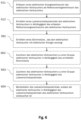
- Fig. 6 shows schematically a method according to an embodiment of the invention.
- the Fig. 6 The method shown is based on the Fig. 1 and differs therefrom in that it may include steps S61 to S64, each of which is optional.
- the method can optionally include the steps S61 determining a power grid that supplies the electrical consumer with electrical energy and the step S62 assigning the electrical consumer to a group of electrical consumers depending on the determined power grid.
- power grids are low-voltage grids, medium-voltage grids, high-voltage grids, extra-high-voltage grids and/or direct current grids. This can have the advantage that current peaks or load peaks in a power grid can be compensated by means of the load shifting potential of an electrical consumer that is supplied with electrical energy in said power grid.
- the method can include a step S63 of assigning the electrical consumer to a group of electrical consumers depending on the load shift potential. This allows a large number of electrical consumers to be used in a particularly simple manner to compensate for current or load peaks.
- the method can also include a step S64 of providing the load shifting potential so that the electrical consumer can be controlled depending on the load shifting potential of the electrical consumer. Control can be carried out, for example, by means of a demand response signal.
- This can have the advantage that the load shifting potential can be provided to an energy supplier who supplies the electrical consumer with electrical energy without private information, for example about the heating behavior of residents of a house that is heated or cooled by the electrical consumer, being passed on.
- the Fig. 1 to 6 the determination of a charging time constant (S21), a discharging time constant (S22) and/or an electrical load capacity (S23) can be carried out depending on one or more of the methods and method steps shown in the figure descriptions of the Figures 3 to 6
- the parameters/values determined and/or recorded in the Fig. 1 to 6 The steps shown can be swapped, combined, omitted, added, combined, carried out in parallel and/or divided into several steps without affecting the essence of the invention.
- the electrical consumer can be set up to provide heat or cold in several circuits, where one circuit is a heating and/or cooling circuit. Detecting the reference energy consumption of the electrical consumer can then include detecting the control of the several circuits. Accordingly, determining the load shifting potential can include determining the load shifting potential for at least one circuit of the several circuits. In some embodiments, several circuits can be combined to form a circuit group for which a load shifting potential is determined together. In some embodiments, a charging time constant, a discharging time constant and/or a load capacity can be determined accordingly for at least one circuit of the one or more circuits or for a circuit group.
- Fig. 7 shows a diagram for determining a load shift potential according to an embodiment of the invention.
- the time is plotted on the X-axis.
- the state of charge in percent is indicated on the Y-axis.
- the Fig. 7 The graph shown can be divided into two sections 71, 72. Section 71 has approximately the form of a logarithmic function, section 72 has approximately the form of an exponential function.
- the graph, comprising sections 71 and 72 shows, by way of example, the charge state of one or more heating or cooling circuits that are supplied with heat or cold by means of an electrical consumer.
- the electrical consumer In section 71, the electrical consumer generates heat or cold so that the heating or cooling circuits are saturated by the electrical consumer according to specified target temperatures analogous to a capacity or a capacitor. During this time, the electrical consumer is in load operation so that heat is generated for one or more heating circuits or cold is generated for one or more cooling circuits.
- the period of load operation can be referred to as the loading time.
- Fig. 7 It can be seen that after a period of time 1 ⁇ 1 a state of charge of 63% is reached, after 2 ⁇ 1 a state of charge of about 86%, after 3 ⁇ 1 a state of charge of about 95% and after 4 ⁇ 1 a state of charge of about 98% is reached.
- the value ⁇ 1 can be the charging time constant.
- a load mode can be exited at a lower predetermined charge level, in particular so that a reserve (overcharge potential) is maintained.
- a discharge time constant in particular a discharge time constant ⁇ 2 , can be determined using graph section 72 based on graph section 72.
- the state of charge shows a state of charge of the load capacity of the electrical consumer in percent.
- the load capacity thus represents a measure of the storage reserves of the heating or cooling circuits supplied with heat or cold by the electrical consumer.
- the state of charge can be more than 100%, so that overcharging is possible depending on an overcharging potential.
- Fig. 8 shows schematically a relationship between a daily average temperature and a heating power or a cooling power of an electrical consumer according to an embodiment of the invention.
- a graph 80 is shown in which the daily mean temperature in degrees Celsius is plotted on the X-axis and the heating output (positive values) or the cooling output (negative values) in watts is plotted on the Y-axis. From the graph 80 it can be seen that there is a direct connection between the daily mean temperature and heating output, so that the measuring points 83 can be reproduced/approximated/interpolated as a connection between the daily mean temperature and heating output using a straight line equation 84 or another mathematical function.
- Graph 80 shows that the measuring points 81 show an interaction between the daily mean temperature and the cooling capacity This interaction can be approximated/reproduced/interpolated using a straight line equation 82 or another mathematical function. Based on this, it is possible to approximately estimate the energy consumption of an electrical consumer to supply a cooling circuit with cold as a function of a daily average temperature. This has the advantage that the energy consumption of an electrical consumer can be estimated as a function of the daily average temperature and a load shift potential can be determined accordingly as a function of a daily average temperature.
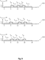
- Fig. 9 shows schematically a power of an electrical consumer as a function of time according to an embodiment of the invention.
- Three graphs are shown for this purpose, with graph 101 showing a power curve (power of the electrical consumer as a function of time) for a first day, graph 102 a power curve for a second day and graph 103 a power curve for a third day as a function of time.
- the time is plotted on the x-axis in hours and the electrical power of the electrical consumer on the y-axis.
- T Be of an operating interval load operation
- the electrical consumer is operated with a power P 1 .
- the electrical consumer is in load operation for the duration T Be at around 6 a.m., 12 p.m. and 6 p.m.
- the time periods T En,1a , T En,1b , T En,1c have approximately the same duration.
- the time periods T En,3a and T En,3b also have approximately the same length.
- the time periods can also have different durations or show other regularities (e.g. always a long load operation in the morning, always a short load operation in the evening, or similar).
- a load shifting potential can be determined in such a way that load peaks or current peaks in a power grid are optimally compensated and at the same time it is ensured that the electrical consumers supply a heating circuit or a cooling circuit with heat or cold according to user requirements.
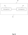
- Fig. 10 shows a system according to an embodiment of the invention.
- the system 90 comprises a detection unit 91 and a determination unit 92.
- the detection unit is designed to detect an electrical energy consumption of an electrical consumer as a reference energy consumption of the electrical consumer.
- the determination unit is designed to determine a load shift potential of the electrical consumer depending on the reference energy consumption of the electrical consumer.
- the system 90 can be designed to Fig. 1 to 6
- the system may comprise additional units.
- the detection unit 91 may be configured to perform a detection according to one of the Fig. 1 to 6
- the determination unit 92 may, for example, be configured to carry out a determination according to one of the steps shown in the Fig. 1 to 6 steps shown.
- a signal processing unit 93 of an electrical consumer can comprise the detection unit and/or the determination unit.
- an independent signal processing unit 93 in particular a signal processing unit 93 that is independent of the electrical consumer, can comprise the detection unit and/or the determination unit. This can have the advantage that existing heat or cold supply systems can be retrofitted in a simple manner with a detection unit and/or a determination unit, so that a load shift potential can be determined.
- the detection unit 91 can be set up to detect the electrical energy consumption of a large number of electrical consumers.
- the determination unit 92 can be set up to determine the load shift potential of a large number of electrical consumers. This can have the advantage that a load shift potential of a large number of electrical consumers can be determined cost-effectively by means of a detection unit or a determination unit.
- the system may include a communication unit (not in Fig. 10 shown).
- the communication unit can be configured, for example, to send one or more control signals, in particular a demand response signal, to an electrical consumer and/or to receive data from one or more electrical consumers.
- the communication unit can be configured to query data, in particular from an electrical consumer, from a cloud storage device. This data can have been previously stored in the cloud storage device by an electrical consumer, for example.
- detecting the detection unit may include requesting data by means of the communication unit and/or reading/processing data that the communication unit has received.
- the communication unit can be set up to send an offer for a load shift depending on the determined load shift potential and/or to receive a demand request for a load shift.
- a network operator can then accept the offered load shift, in particular in part, so that a control signal, in particular a demand response signal, is transmitted to an electrical consumer depending on one or more determined load shift potentials.
- a control signal in particular a demand response signal, can be transmitted to an electrical consumer depending on its load shift potential, in particular by means of the communication unit.
- the communication unit can be configured to provide a load shifting potential of an electrical consumer, in particular in connection with a reference to a power grid in which the electrical consumer is arranged, in a database, a cloud storage, a digital marketplace, etc.
- the detection unit 91 may be configured to detect additional heat generation units, such as a solar system, a wood-fired heating system, a gas boiler, an oil boiler, etc., and to The determination unit can be set up to determine the load shift potential depending on the other heat generators and depending on information data that influence the operation of the other heat generators. Corresponding information data can be, for example, temperatures, predicted hours of sunshine, efficiency of the heat generator, etc.
Landscapes
- Engineering & Computer Science (AREA)
- Physics & Mathematics (AREA)
- Thermal Sciences (AREA)
- Chemical & Material Sciences (AREA)
- Combustion & Propulsion (AREA)
- Mechanical Engineering (AREA)
- General Engineering & Computer Science (AREA)
- Power Engineering (AREA)
- General Physics & Mathematics (AREA)
- Charge And Discharge Circuits For Batteries Or The Like (AREA)
- Supply And Distribution Of Alternating Current (AREA)
Claims (15)
- Procédé de détermination d'un potentiel de décalage de charge d'un consommateur électrique, le consommateur électrique étant conçu pour produire de la chaleur et/ou du froid dans un ou plusieurs circuits de chauffage et/ou de refroidissement, comprenant les étapes suivantes :détection (S11) d'une consommation d'énergie électrique du consommateur électrique en tant que consommation d'énergie de référence du consommateur électrique ;détermination (S12) d'un potentiel de décalage de charge du consommateur électrique en fonction de la consommation d'énergie de référence détectée du consommateur électrique, caractérisé en ce quele potentiel de décalage de charge est une mesure de la mesure dans laquelle une adaptation d'une charge électrique du consommateur électrique est possible en ce qui concerne un instant d'une consommation d'énergie du consommateur électrique.
- Procédé selon la revendication 1, comprenant l'étape supplémentaire suivante :détermination (S21) d'une constante de temps de charge (τ1) du consommateur électrique en fonction de la consommation d'énergie de référence détectée ;la détermination du potentiel de décalage de charge étant effectuée en fonction de la constante de temps de charge du consommateur électrique,la détermination d'une constante de temps de charge du consommateur électrique étant effectuée en fonction d'une durée d'un ou de plusieurs intervalles de fonctionnement du consommateur électrique.
- Procédé selon la revendication 1 ou 2, comprenant l'étape supplémentaire suivante :détermination (S22) d'une constante de temps de décharge (τ2) du consommateur électrique en fonction de la consommation d'énergie de référence détectée ;la détermination du potentiel de décalage de charge étant effectuée en fonction de la constante de temps de décharge du consommateur électrique,la détermination d'une constante de temps de décharge du consommateur électrique étant effectuée en fonction d'une longueur d'une ou de plusieurs périodes de temps respectivement entre deux intervalles de fonctionnement successifs du consommateur électrique.
- Procédé selon l'une quelconque des revendications 1 à 3, comprenant l'étape supplémentaire suivante :détermination (S23) d'une capacité de charge électrique du consommateur électrique en fonction de la consommation d'énergie de référence détectée ;la détermination du potentiel de décalage de charge étant effectuée en fonction de la capacité de charge électrique du consommateur électrique,la détermination de la capacité de charge électrique du consommateur électrique étant effectuée en fonction d'une puissance électrique du consommateur électrique pendant la durée d'un ou de plusieurs intervalles de fonctionnement du consommateur électrique et/ou en fonction d'une consommation d'énergie pendant la durée d'un ou de plusieurs intervalles de fonctionnement du consommateur électrique.
- Procédé selon l'une quelconque des revendications 1 à 4,la détection (S11) de la consommation d'énergie de référence comprenant l'étape suivante :
détection d'un temps de fonctionnement total du consommateur électrique dans une première durée prédéfinie ; et/oule procédé comprenant l'étape supplémentaire suivante :détection (S31) d'un temps de fonctionnement actuel du consommateur électrique dans un premier intervalle de temps actuel ;la détermination (S12) du potentiel de décalage de charge étant effectuée en fonction du temps de fonctionnement total du consommateur électrique et/ou en outre en fonction du temps de fonctionnement actuel du consommateur électrique. - Procédé selon l'une quelconque des revendications 1 à 5,la détection (S11) de la consommation d'énergie de référence comprenant l'étape suivante :
détection d'une consommation d'énergie totale du consommateur électrique dans une deuxième durée prédéfinie ; et/oule procédé comprenant l'étape supplémentaire suivante :détection (S32) d'une consommation d'énergie actuelle du consommateur électrique dans un deuxième intervalle de temps actuel ;la détermination (S12) du potentiel de décalage de charge étant effectuée en fonction de la consommation d'énergie totale du consommateur électrique et/ou en outre en fonction de la consommation d'énergie actuelle du consommateur électrique. - Procédé selon l'une quelconque des revendications 1 à 6, comprenant les étapes supplémentaires suivantes :prédétermination (S41) d'une température de consigne pour un circuit de chauffage et/ou de refroidissement du consommateur électrique ; et/oudétection (S42) d'une température réelle pour un circuit de chauffage et/ou de refroidissement du ou des consommateurs électriques ;la détermination (S12) du potentiel de décalage de charge étant effectuée en outre en fonction de la température de consigne détectée et/ou en outre en fonction de la température réelle détectée.
- Procédé selon l'une quelconque des revendications 1 à 7, comprenant les étapes supplémentaires suivantes :détection (S51) d'une température extérieure en tant que température extérieure de référence en liaison avec la détection de la consommation d'énergie de référence du consommateur électrique ; et/oudétection (S54) d'une température extérieure actuelle ;la détermination (S12) du potentiel de décalage de charge étant effectuée en outre en fonction de la température extérieure de référence et/ou en outre en fonction de la température extérieure actuelle.
- Procédé selon l'une quelconque des revendications 1 à 8,le consommateur électrique étant conçu pour fournir de la chaleur et/ou du froid dans plusieurs circuits, un circuit étant un circuit de chauffage et/ou de refroidissement ;la détection (S11) de la consommation d'énergie de référence du consommateur électrique comprenant une détection de la commande des plusieurs circuits ;la détermination (S12) du potentiel de décalage de charge comprenant une détermination du potentiel de décalage de charge pour au moins un circuit des plusieurs circuits ; et/ou le procédé comprenant en outre l'étape suivante :détermination (S57) d'un potentiel de surcharge du consommateur électrique et/ou des un ou plusieurs circuits ;la détermination (S12) du potentiel de décalage de charge étant effectuée en outre en fonction du potentiel de surcharge déterminé.
- Procédé selon l'une quelconque des revendications 1 à 9, comprenant les étapes supplémentaires suivantes :fourniture du potentiel de décalage de charge, de sorte que le consommateur électrique peut être commandé en fonction du potentiel de décalage de charge du consommateur électrique, une commande du consommateur électrique étant effectuée en particulier au moyen d'un signal demande-réponse ; et éventuellement émission d'un message de retour du consommateur électrique indiquant si et/ou dans quelle mesure un décalage de charge du consommateur électrique est effectué lorsqu'un signal de commande, en particulier un signal demande-réponse, est transmis au consommateur électrique sur la base du potentiel de décalage de charge ; et/oudétection (S52) d'une température de circuit de chauffage, d'une température de circuit de refroidissement, d'une température de consigne et/ou d'une température de bâtiment en tant que températures de référence en liaison avec la détection de la consommation d'énergie de référence du consommateur électrique ; et/oudétection (S55) d'une température de circuit de chauffage actuelle, d'une température de circuit de refroidissement actuelle, d'une température de consigne actuelle et/ou d'une température de bâtiment actuelle en tant que températures actuelles ;la détermination (S12) du potentiel de décalage de charge étant effectuée en outre en fonction des températures de référence et/ou en outre en fonction des températures actuelles ; et/oudétection (S53) de facteurs environnementaux en tant que facteurs environnementaux de référence en liaison avec la détection de la consommation d'énergie de référence ; et/oudétection (S56) de facteurs environnementaux actuels ;la détermination du potentiel de décalage de charge (S12) étant effectuée en outre en fonction des facteurs environnementaux de référence détectés et/ou en fonction des facteurs environnementaux actuels.
- Procédé selon l'une quelconque des revendications 1 à 10, comprenant les étapes supplémentaires suivantes :détermination (S61) d'un réseau électrique qui alimente le consommateur électrique en énergie électrique ; etaffectation (S62, S63) du consommateur électrique à un groupe de consommateurs électriques en fonction du réseau électrique déterminé et/ou du potentiel de décalage de charge.
- Système (90) de détermination d'un potentiel de décalage de charge d'un consommateur électrique, le consommateur électrique étant conçu pour produire de la chaleur et/ou du froid dans un ou plusieurs circuits de chauffage et/ou de refroidissement, comprenant :une unité de détection (91) pour détecter une consommation d'énergie électrique du consommateur électrique en tant que consommation d'énergie de référence du consommateur électrique ; etune unité de détermination (92) pour déterminer un potentiel de décalage de charge du consommateur électrique en fonction de la consommation d'énergie de référence du consommateur électrique, caractérisé en ce quele potentiel de décalage de charge est une mesure de la mesure dans laquelle une adaptation d'une charge électrique du consommateur électrique est possible en ce qui concerne un instant d'une consommation d'énergie du consommateur électrique.
- Système (90) selon la revendication 12,une unité de traitement de signal (93) du consommateur électrique comprenant l'unité de détection et/ou l'unité de détermination ; oule système comprenant une unité de traitement de signal (93) qui comprend l'unité de détection (91) et/ou l'unité de détermination (92) ; et/oule système comprenant une unité de communication qui est conçue pour envoyer une offre pour un décalage de charge en fonction du potentiel de décalage de charge déterminé et/ou pour recevoir une demande de demande pour un décalage de charge.
- Système (90) selon l'une quelconque des revendications 12 ou 13,l'unité de détection (91) étant conçue pour détecter la consommation d'énergie électrique d'une pluralité de consommateurs électriques et/oul'unité de détermination (92) étant conçue pour déterminer le potentiel de décalage de charge d'une pluralité de consommateurs électriques.
- Produit de programme informatique comprenant des instructions qui, lorsque le programme est exécuté par un système selon l'une quelconque des revendications 12 à 14, amènent celui-ci à exécuter les étapes du procédé selon l'une quelconque des revendications 1 à 11.
Applications Claiming Priority (1)
| Application Number | Priority Date | Filing Date | Title |
|---|---|---|---|
| DE102020215070.2A DE102020215070A1 (de) | 2020-11-30 | 2020-11-30 | Verfahren, system und computerprogramm-produkt zum ermitteln eines lastverschiebepotentials eines elektrischen verbrauchers |
Publications (3)
| Publication Number | Publication Date |
|---|---|
| EP4006559A1 EP4006559A1 (fr) | 2022-06-01 |
| EP4006559C0 EP4006559C0 (fr) | 2025-02-19 |
| EP4006559B1 true EP4006559B1 (fr) | 2025-02-19 |
Family
ID=78806399
Family Applications (1)
| Application Number | Title | Priority Date | Filing Date |
|---|---|---|---|
| EP21210854.2A Active EP4006559B1 (fr) | 2020-11-30 | 2021-11-26 | Procédé, système et produit-programme informatique permettant de déterminer un potentiel de déplacement de charge d'un consommateur électrique |
Country Status (3)
| Country | Link |
|---|---|
| EP (1) | EP4006559B1 (fr) |
| DE (1) | DE102020215070A1 (fr) |
| PL (1) | PL4006559T3 (fr) |
Family Cites Families (9)
| Publication number | Priority date | Publication date | Assignee | Title |
|---|---|---|---|---|
| US8805597B2 (en) | 2009-02-10 | 2014-08-12 | Steffes Corporation | Electrical appliance energy consumption control |
| DE102009010117A1 (de) * | 2009-02-24 | 2010-09-02 | Peter Breuning | Verfahren zur Vergleichmäßigung der Bezugsleistung von elektrischer Energie bei einem Endverbraucher |
| DE102011080830A1 (de) | 2011-08-11 | 2013-02-14 | Stephan Holzner | Speicher für elektrische Energie |
| JP5494696B2 (ja) | 2012-02-27 | 2014-05-21 | ダイキン工業株式会社 | ヒートポンプ機器エネルギー管理装置 |
| DE102013214996A1 (de) * | 2013-07-31 | 2014-07-31 | Siemens Aktiengesellschaft | Vorrichtung zur Lastverschiebung in intelligenten Stromverteilungsnetzen und ein entsprechendes System |
| DE102017217055A1 (de) * | 2017-09-26 | 2019-03-28 | Robert Bosch Gmbh | Energieflusssteuergerät zur Steuerung einer Lastverschiebung |
| DE102017220414A1 (de) | 2017-11-16 | 2019-05-16 | Robert Bosch Gmbh | Verfahren zum Betreiben eines eine Wärmepumpe aufweisenden Wärmespeichersystems |
| DE102017129744A1 (de) | 2017-12-13 | 2019-06-13 | i-select SA | Technik zum dezentralen Speichern von Energie |
| DE102018116845A1 (de) | 2018-07-11 | 2020-01-16 | ait-deutschland GmbH | Verfahren zum Betreiben einer Wärmepumpe |
-
2020
- 2020-11-30 DE DE102020215070.2A patent/DE102020215070A1/de active Pending
-
2021
- 2021-11-26 PL PL21210854.2T patent/PL4006559T3/pl unknown
- 2021-11-26 EP EP21210854.2A patent/EP4006559B1/fr active Active
Also Published As
| Publication number | Publication date |
|---|---|
| PL4006559T3 (pl) | 2025-06-09 |
| EP4006559A1 (fr) | 2022-06-01 |
| DE102020215070A1 (de) | 2022-06-02 |
| EP4006559C0 (fr) | 2025-02-19 |
Similar Documents
| Publication | Publication Date | Title |
|---|---|---|
| EP3590169B1 (fr) | Procédé de gestion d'énergie pour système énergétique et système énergétique | |
| DE102016214332B4 (de) | Aggregierte und optimierte virtuelles-kraftwerk-steuerung | |
| EP3214718B1 (fr) | Procede et systeme de fonctionnement d'un reseau d'alimentation en energie autarcique | |
| EP3107174B1 (fr) | Procédé, dispositif de commande et système de fonctionnement d'un sous-réseau d'un réseau de distribution d'énergie | |
| EP2834573B1 (fr) | Système de fourniture de chaleur et procédé permettant de faire fonctionner ledit système | |
| DE112017003022T5 (de) | Verwaltungssystem für elektrische Leistung | |
| DE102016015503A1 (de) | Heiz- und/oder Kühlsystem mit prädiktivem Energiemanagement | |
| EP3161928B1 (fr) | Système de gestion d'énergie permettant de commander un dispositif, produit-programme d'ordinateur et procédé de commande d'un dispositif | |
| EP3561983A1 (fr) | Procédé de fonctionnement d'un système d'alimentation en énergie | |
| WO2016138885A1 (fr) | Procédé de commande de la consommation d'énergie d'une unité d'immeuble et unité de distribution décentralisée d'énergie | |
| EP3284152B1 (fr) | Commande de transfert d'énergie entre un réseau d'alimentation en énergie et des dispositifs d'utilisateur final sur la base du flux d'énergie et de la qualité du réseau | |
| DE202017007300U1 (de) | Elektrische Energieverwaltung | |
| DE102010001874A1 (de) | Speicher für elektrische Energie | |
| EP4006559B1 (fr) | Procédé, système et produit-programme informatique permettant de déterminer un potentiel de déplacement de charge d'un consommateur électrique | |
| EP3906522B1 (fr) | Processus de gestion de l'énergie assisté par ordinateur et système de gestion de l'énergie | |
| EP2854250A2 (fr) | Procédé d'analyse d'un signal de composition agrégé et de commande de charge dans un système d'alimentation électrique | |
| DE19817191C2 (de) | Verfahren zum Regeln der Gesamtleistung von energietechnischen Anlagen, insbesondere einer Gruppe von elektrischen Verbrauchern | |
| AT512672A2 (de) | Verfahren zur Bestimmung von Messstellen in Niederspannungsnetzen und Netzmanagementsubsystem zur Durchführung des Verfahrens | |
| DE102019121990A1 (de) | Verfahren zur Modellierung einer oder mehrerer Energiewandlungsanlagen in einem Energiemanagementsystem | |
| DE102021121795B4 (de) | VDE-FNN-Steuerbox für die elektrische Steuerung von Energieflüssen in einem Heimenergienetz | |
| DE102023102702A1 (de) | Eigenverbrauchsoptimierung für haushaltsnetze mit batteriespeicher | |
| DE102023109749A1 (de) | Vorhersage der verbrauchernachfrage nach einem angebot in einergeografischen zone auf der grundlage unzuverlässiger undnichtstationärer daten | |
| EP4470085A1 (fr) | Procédé pour faire fonctionner une source d'énergie | |
| EP3072202B1 (fr) | Procédé et dispositif permettant la gestion à rendement contrôlé d'un système d'accumulation pour un système photovoltaïque | |
| EP3664243B1 (fr) | Planification de fonctionnement prédictive dans un micro-réseau en fonction des fenêtres temporelles de charge élevé d'un réseau électrique principal |
Legal Events
| Date | Code | Title | Description |
|---|---|---|---|
| PUAI | Public reference made under article 153(3) epc to a published international application that has entered the european phase |
Free format text: ORIGINAL CODE: 0009012 |
|
| STAA | Information on the status of an ep patent application or granted ep patent |
Free format text: STATUS: THE APPLICATION HAS BEEN PUBLISHED |
|
| AK | Designated contracting states |
Kind code of ref document: A1 Designated state(s): AL AT BE BG CH CY CZ DE DK EE ES FI FR GB GR HR HU IE IS IT LI LT LU LV MC MK MT NL NO PL PT RO RS SE SI SK SM TR |
|
| STAA | Information on the status of an ep patent application or granted ep patent |
Free format text: STATUS: REQUEST FOR EXAMINATION WAS MADE |
|
| 17P | Request for examination filed |
Effective date: 20221201 |
|
| RBV | Designated contracting states (corrected) |
Designated state(s): AL AT BE BG CH CY CZ DE DK EE ES FI FR GB GR HR HU IE IS IT LI LT LU LV MC MK MT NL NO PL PT RO RS SE SI SK SM TR |
|
| REG | Reference to a national code |
Ref country code: DE Free format text: PREVIOUS MAIN CLASS: G01R0019250000 Ipc: F24H0015164000 Ref country code: DE Ref legal event code: R079 Ref document number: 502021006690 Country of ref document: DE Free format text: PREVIOUS MAIN CLASS: G01R0019250000 Ipc: F24H0015164000 |
|
| GRAP | Despatch of communication of intention to grant a patent |
Free format text: ORIGINAL CODE: EPIDOSNIGR1 |
|
| STAA | Information on the status of an ep patent application or granted ep patent |
Free format text: STATUS: GRANT OF PATENT IS INTENDED |
|
| RIC1 | Information provided on ipc code assigned before grant |
Ipc: H02J 3/14 20060101ALI20241014BHEP Ipc: G01R 19/25 20060101ALI20241014BHEP Ipc: F24H 15/269 20220101ALI20241014BHEP Ipc: F24H 15/172 20220101ALI20241014BHEP Ipc: F24H 15/168 20220101ALI20241014BHEP Ipc: F24H 15/164 20220101AFI20241014BHEP |
|
| INTG | Intention to grant announced |
Effective date: 20241029 |
|
| GRAS | Grant fee paid |
Free format text: ORIGINAL CODE: EPIDOSNIGR3 |
|
| GRAA | (expected) grant |
Free format text: ORIGINAL CODE: 0009210 |
|
| STAA | Information on the status of an ep patent application or granted ep patent |
Free format text: STATUS: THE PATENT HAS BEEN GRANTED |
|
| AK | Designated contracting states |
Kind code of ref document: B1 Designated state(s): AL AT BE BG CH CY CZ DE DK EE ES FI FR GB GR HR HU IE IS IT LI LT LU LV MC MK MT NL NO PL PT RO RS SE SI SK SM TR |
|
| REG | Reference to a national code |
Ref country code: GB Ref legal event code: FG4D Free format text: NOT ENGLISH |
|
| REG | Reference to a national code |
Ref country code: CH Ref legal event code: EP |
|
| REG | Reference to a national code |
Ref country code: IE Ref legal event code: FG4D Free format text: LANGUAGE OF EP DOCUMENT: GERMAN |
|
| REG | Reference to a national code |
Ref country code: DE Ref legal event code: R096 Ref document number: 502021006690 Country of ref document: DE |
|
| RAP2 | Party data changed (patent owner data changed or rights of a patent transferred) |
Owner name: VIESSMANN HOLDING INTERNATIONAL GMBH |
|
| U01 | Request for unitary effect filed |
Effective date: 20250305 |
|
| U07 | Unitary effect registered |
Designated state(s): AT BE BG DE DK EE FI FR IT LT LU LV MT NL PT RO SE SI Effective date: 20250312 |
|
| PG25 | Lapsed in a contracting state [announced via postgrant information from national office to epo] |
Ref country code: RS Free format text: LAPSE BECAUSE OF FAILURE TO SUBMIT A TRANSLATION OF THE DESCRIPTION OR TO PAY THE FEE WITHIN THE PRESCRIBED TIME-LIMIT Effective date: 20250519 |
|
| PG25 | Lapsed in a contracting state [announced via postgrant information from national office to epo] |
Ref country code: ES Free format text: LAPSE BECAUSE OF FAILURE TO SUBMIT A TRANSLATION OF THE DESCRIPTION OR TO PAY THE FEE WITHIN THE PRESCRIBED TIME-LIMIT Effective date: 20250219 |
|
| PG25 | Lapsed in a contracting state [announced via postgrant information from national office to epo] |
Ref country code: IS Free format text: LAPSE BECAUSE OF FAILURE TO SUBMIT A TRANSLATION OF THE DESCRIPTION OR TO PAY THE FEE WITHIN THE PRESCRIBED TIME-LIMIT Effective date: 20250619 Ref country code: NO Free format text: LAPSE BECAUSE OF FAILURE TO SUBMIT A TRANSLATION OF THE DESCRIPTION OR TO PAY THE FEE WITHIN THE PRESCRIBED TIME-LIMIT Effective date: 20250519 |
|
| PG25 | Lapsed in a contracting state [announced via postgrant information from national office to epo] |
Ref country code: HR Free format text: LAPSE BECAUSE OF FAILURE TO SUBMIT A TRANSLATION OF THE DESCRIPTION OR TO PAY THE FEE WITHIN THE PRESCRIBED TIME-LIMIT Effective date: 20250219 |
|
| PG25 | Lapsed in a contracting state [announced via postgrant information from national office to epo] |
Ref country code: GR Free format text: LAPSE BECAUSE OF FAILURE TO SUBMIT A TRANSLATION OF THE DESCRIPTION OR TO PAY THE FEE WITHIN THE PRESCRIBED TIME-LIMIT Effective date: 20250520 |
|
| PG25 | Lapsed in a contracting state [announced via postgrant information from national office to epo] |
Ref country code: SM Free format text: LAPSE BECAUSE OF FAILURE TO SUBMIT A TRANSLATION OF THE DESCRIPTION OR TO PAY THE FEE WITHIN THE PRESCRIBED TIME-LIMIT Effective date: 20250219 |
|
| PG25 | Lapsed in a contracting state [announced via postgrant information from national office to epo] |
Ref country code: CZ Free format text: LAPSE BECAUSE OF FAILURE TO SUBMIT A TRANSLATION OF THE DESCRIPTION OR TO PAY THE FEE WITHIN THE PRESCRIBED TIME-LIMIT Effective date: 20250219 |
|
| PG25 | Lapsed in a contracting state [announced via postgrant information from national office to epo] |
Ref country code: SK Free format text: LAPSE BECAUSE OF FAILURE TO SUBMIT A TRANSLATION OF THE DESCRIPTION OR TO PAY THE FEE WITHIN THE PRESCRIBED TIME-LIMIT Effective date: 20250219 |
|
| U20 | Renewal fee for the european patent with unitary effect paid |
Year of fee payment: 5 Effective date: 20251022 |
|
| REG | Reference to a national code |
Ref country code: CH Ref legal event code: U11 Free format text: ST27 STATUS EVENT CODE: U-0-0-U10-U11 (AS PROVIDED BY THE NATIONAL OFFICE) Effective date: 20251201 |
|
| PLBE | No opposition filed within time limit |
Free format text: ORIGINAL CODE: 0009261 |
|
| STAA | Information on the status of an ep patent application or granted ep patent |
Free format text: STATUS: NO OPPOSITION FILED WITHIN TIME LIMIT |
|
| PGFP | Annual fee paid to national office [announced via postgrant information from national office to epo] |
Ref country code: GB Payment date: 20251022 Year of fee payment: 5 |
|
| PGFP | Annual fee paid to national office [announced via postgrant information from national office to epo] |
Ref country code: CH Payment date: 20251201 Year of fee payment: 5 |
|
| PGFP | Annual fee paid to national office [announced via postgrant information from national office to epo] |
Ref country code: PL Payment date: 20251022 Year of fee payment: 5 |
|
| 26N | No opposition filed |
Effective date: 20251120 |