EP4006567A1 - Système magnétique destiné à la mise en oeuvre des expériences rmn à 2 champs et procédé de mise à niveau associé - Google Patents
Système magnétique destiné à la mise en oeuvre des expériences rmn à 2 champs et procédé de mise à niveau associé Download PDFInfo
- Publication number
- EP4006567A1 EP4006567A1 EP21208809.0A EP21208809A EP4006567A1 EP 4006567 A1 EP4006567 A1 EP 4006567A1 EP 21208809 A EP21208809 A EP 21208809A EP 4006567 A1 EP4006567 A1 EP 4006567A1
- Authority
- EP
- European Patent Office
- Prior art keywords
- bore
- additional
- magnet
- vacuum
- container
- Prior art date
- Legal status (The legal status is an assumption and is not a legal conclusion. Google has not performed a legal analysis and makes no representation as to the accuracy of the status listed.)
- Granted
Links
Images


Classifications
-
- G—PHYSICS
- G01—MEASURING; TESTING
- G01R—MEASURING ELECTRIC VARIABLES; MEASURING MAGNETIC VARIABLES
- G01R33/00—Arrangements or instruments for measuring magnetic variables
- G01R33/20—Arrangements or instruments for measuring magnetic variables involving magnetic resonance
- G01R33/28—Details of apparatus provided for in groups G01R33/44 - G01R33/64
- G01R33/30—Sample handling arrangements, e.g. sample cells, spinning mechanisms
- G01R33/307—Sample handling arrangements, e.g. sample cells, spinning mechanisms specially adapted for moving the sample relative to the MR system, e.g. spinning mechanisms, flow cells or means for positioning the sample inside a spectrometer
-
- G—PHYSICS
- G01—MEASURING; TESTING
- G01R—MEASURING ELECTRIC VARIABLES; MEASURING MAGNETIC VARIABLES
- G01R33/00—Arrangements or instruments for measuring magnetic variables
- G01R33/20—Arrangements or instruments for measuring magnetic variables involving magnetic resonance
- G01R33/28—Details of apparatus provided for in groups G01R33/44 - G01R33/64
- G01R33/38—Systems for generation, homogenisation or stabilisation of the main or gradient magnetic field
- G01R33/381—Systems for generation, homogenisation or stabilisation of the main or gradient magnetic field using electromagnets
- G01R33/3815—Systems for generation, homogenisation or stabilisation of the main or gradient magnetic field using electromagnets with superconducting coils, e.g. power supply therefor
-
- G—PHYSICS
- G01—MEASURING; TESTING
- G01R—MEASURING ELECTRIC VARIABLES; MEASURING MAGNETIC VARIABLES
- G01R33/00—Arrangements or instruments for measuring magnetic variables
- G01R33/20—Arrangements or instruments for measuring magnetic variables involving magnetic resonance
- G01R33/28—Details of apparatus provided for in groups G01R33/44 - G01R33/64
- G01R33/38—Systems for generation, homogenisation or stabilisation of the main or gradient magnetic field
- G01R33/3804—Additional hardware for cooling or heating of the magnet assembly, for housing a cooled or heated part of the magnet assembly or for temperature control of the magnet assembly
-
- G—PHYSICS
- G01—MEASURING; TESTING
- G01R—MEASURING ELECTRIC VARIABLES; MEASURING MAGNETIC VARIABLES
- G01R33/00—Arrangements or instruments for measuring magnetic variables
- G01R33/20—Arrangements or instruments for measuring magnetic variables involving magnetic resonance
- G01R33/28—Details of apparatus provided for in groups G01R33/44 - G01R33/64
- G01R33/38—Systems for generation, homogenisation or stabilisation of the main or gradient magnetic field
- G01R33/387—Compensation of inhomogeneities
- G01R33/3873—Compensation of inhomogeneities using ferromagnetic bodies ; Passive shimming
-
- H—ELECTRICITY
- H01—ELECTRIC ELEMENTS
- H01F—MAGNETS; INDUCTANCES; TRANSFORMERS; SELECTION OF MATERIALS FOR THEIR MAGNETIC PROPERTIES
- H01F6/00—Superconducting magnets; Superconducting coils
- H01F6/04—Cooling
-
- G—PHYSICS
- G01—MEASURING; TESTING
- G01R—MEASURING ELECTRIC VARIABLES; MEASURING MAGNETIC VARIABLES
- G01R33/00—Arrangements or instruments for measuring magnetic variables
- G01R33/20—Arrangements or instruments for measuring magnetic variables involving magnetic resonance
- G01R33/28—Details of apparatus provided for in groups G01R33/44 - G01R33/64
- G01R33/38—Systems for generation, homogenisation or stabilisation of the main or gradient magnetic field
- G01R33/387—Compensation of inhomogeneities
- G01R33/3875—Compensation of inhomogeneities using correction coil assemblies, e.g. active shimming
-
- G—PHYSICS
- G01—MEASURING; TESTING
- G01R—MEASURING ELECTRIC VARIABLES; MEASURING MAGNETIC VARIABLES
- G01R33/00—Arrangements or instruments for measuring magnetic variables
- G01R33/20—Arrangements or instruments for measuring magnetic variables involving magnetic resonance
- G01R33/44—Arrangements or instruments for measuring magnetic variables involving magnetic resonance using nuclear magnetic resonance [NMR]
- G01R33/445—MR involving a non-standard magnetic field B0, e.g. of low magnitude as in the earth's magnetic field or in nanoTesla spectroscopy, comprising a polarizing magnetic field for pre-polarisation, B0 with a temporal variation of its magnitude or direction such as field cycling of B0 or rotation of the direction of B0, or spatially inhomogeneous B0 like in fringe-field MR or in stray-field imaging
-
- G—PHYSICS
- G01—MEASURING; TESTING
- G01R—MEASURING ELECTRIC VARIABLES; MEASURING MAGNETIC VARIABLES
- G01R33/00—Arrangements or instruments for measuring magnetic variables
- G01R33/20—Arrangements or instruments for measuring magnetic variables involving magnetic resonance
- G01R33/62—Arrangements or instruments for measuring magnetic variables involving magnetic resonance using double resonance
Definitions
- Such a magnet system is from EP 1 747 478 B1 known.
- 2-field NMR spectroscopy is explained, for example, in SF Cousin et al., Phys. Chem.Chem.Phys., 2016, 18, 33187 .
- a 2-field NMR spectrometer has two magnetic centers (locations) with different static magnetic field strengths, at which a sample can be subjected to high-frequency pulses and/or the reaction of the sample can be measured.
- the sample is first exposed to a first, strong magnetic field at a first location (first magnetic center, first sample volume), then to a second location (second magnetic center, second sample volume) at a second, fewer strong magnetic field, where nuclear spins are relaxed and/or manipulated there, and finally the sample is brought back to the location of the first, strong magnetic field, where the actual NMR measurement takes place.
- the polarization can be transferred to a desired atomic nucleus, as a result of which the NMR signal of this atomic nucleus can be amplified in the subsequent NMR measurement.
- this transport should take place quickly, for which purpose a short path between the second location and the first location is desired.
- the usual construction of a magnet system of a 2-field NMR spectrometer has a superconducting magnet (magnetic coil) in a cryostat.
- the first sample volume (first magnetic center) is formed in the magnetic center of the superconducting magnet, which is located in the room temperature bore of the cryostat.
- the second sample volume (second magnetic center) is located in the room-temperature borehole in the stray field of the superconducting magnet, with an approximately homogeneous magnetic field being generated locally by means of ferromagnetic shims.
- Similar magnet systems are from the EP 2 146 215 B1 and the EP 3 081 954 B1 known.
- This magnet setup can be realized with a standard NMR system by installing the ferromagnetic shims in the room temperature bore.
- the disadvantage of this magnet structure is that the field strength in the second sample volume is limited to approximately 0.5 Tesla or less. Furthermore, the field strength in the second sample volume cannot be freely adjusted. When arranging the ferromagnetic shims in the room temperature bore, the installation space is also considerably restricted.
- DNP dynamic nuclear polarization
- the DNP device is designed to generate a magnetic field with a superconducting coil in its own cryostat and is arranged next to a cryostat of the NMR spectrometer. With this arrangement, a standard NMR system can be used, but the path between the sample volume of the DNP device and the sample volume of the NMR spectrometer is quite long, which can cause significant losses in sample polarization.
- a sample can be moved between two positions.
- the one Position is set up in a high-field polarizing magnet that has its own cryostat.
- the other position is established in an auxiliary low field magnet placed above said cryostat.
- a flange connection is used to connect an additional coil container, which contains the additional field magnet to dock.
- the additional coil container with the additional field magnet contained therein protrudes through the flange opening into the RT casing, whereby the additional field magnet or the second sample volume in its magnetic center can move particularly close to the first sample volume.
- the additional field magnet thus uses part of the interior of the cryostat.
- the first sample volume is located at the location of the magnetic center of the main field magnet, which is located in the main coil case in the cryostat.
- a standard NMR magnet system in which only a main field magnet and a first sample volume with a first magnetic field are set up, retrofitting with the additional field magnet to set up the second sample volume is easily possible, in particular by using the flange connection also to attach the additional coil container of the Additional field magnets, usually indirectly via the closure structure.
- the cryostat does not have to be adjusted, or only slightly so, for example by replacing a wall tube of the RT well, if this is to be set up continuously.
- the sealing structure seals the RT jacket at the flange port to be able to maintain the vacuum inside the RT jacket to insulate the main coil case;
- the closure structure replaces the flange cover present in a standard NMR magnet system.
- other structures may be integrated into the closure structure and as a result these other structures (e.g. an auxiliary vacuum vessel) may be involved in the sealing between the flange connection and the RT bore.
- the closure structure does not have to be sealed directly from the environment, but can also be carried out, for example, from a vacuum in an additional vacuum container.
- the second magnetic field in the second sample volume is set up by an additional field magnet that is separate from the main field magnet
- the second magnetic field can basically be chosen arbitrarily and independently of the first magnetic field especially with a field strength greater than 0.5 Tesla.
- the second magnetic field B2 is usually significantly smaller than the first magnetic field B1, preferably with B2 ⁇ 0.33 * B1, particularly preferably with B2 ⁇ 0.25 * B1, and very particularly preferably with B2 ⁇ 0.20 * B1.
- the first magnetic field is mostly 10 Tesla or more, mostly with 10 T ⁇ B1 ⁇ 20 Tesla.
- the second magnetic field B2 is usually 3 Tesla or less, mostly with 0.5 T ⁇ B2 ⁇ 3 T.
- the additional coil case does not restrict the installation space within the RT bore; typically the constant diameter RT bore runs in the area including and between the main coil case and the auxiliary coil case.
- the additional coil case surrounds the room temperature hole.
- the flange connection is typically formed at the top or bottom of the cryostat for a vertically aligned RT bore.
- the flange connection is mostly circular.
- the separate main coil case and auxiliary coil case are thermally decoupled from each other, particularly by the vacuum in the evacuated RT enclosure and the vacuum surrounding the auxiliary coil case. If the magnetic field of the additional field magnet is to be swept, this does not increase the risk of quenching of the main field magnet.
- the main coil case and the auxiliary coil case are typically arranged coaxially to the axis of the room temperature bore, with the main coil case and the auxiliary coil case being arranged next to one another (i.e. one above the other when the axis is arranged vertically) and spaced from one another with respect to this axis.
- the vacuum in which the auxiliary coil case is placed is preferably connected to the vacuum of the evacuated RT envelope.
- the vacuum in which the auxiliary coil case is placed may be separate from the vacuum of the evacuated RT envelope; in this case, an auxiliary vacuum container can be used, in which the auxiliary coil container is arranged.
- the main field magnet and the additional field magnet are preferably electrically isolated from one another.
- the field strength of the additional field magnet is usually adjustable via the electric current in an associated superconducting magnet coil, which is fed with a power supply unit, usually in a range from 0.5 T to 3.0 T. It can be provided that the power supply unit maintains the flow of current during operation (driven mode operation), or the additional field magnet has a superconducting switch, so that a persistent electric current flows during operation (persistent mode operation).
- the cooling of the main coil case and the cooling of the additional coil case are preferably independent of one another.
- the main coil container usually contains liquid and/or super-liquid helium for cooling the main field magnet; if necessary, a cryocooler (such as a pulse tube cooler) can be provided for He reliquefaction; alternatively, a cryogenic-free cooling of the main coil container or the main field magnet contained therein can also be provided with a cryocooler.
- the auxiliary coil case may contain liquid and/or super-liquid helium for cooling; Active, in particular cryogen-free, cooling of the additional coil container or of the additional field magnet contained therein is preferably provided by a cryocooler.
- the auxiliary coil case may be surrounded by its own cooled radiation shield; this radiation shield can be cooled, for example, with liquid nitrogen or via the first cooling stage of a cryocooler, which also cools the additional coil container with one or more further cooling stages.
- a sample for an NMR measurement is prepared at the location of the second sample volume, and the sample is then subjected to the actual NMR measurement at the location of the first sample volume.
- an NMR coil system (for example comprising transmitting and reading coils) is typically arranged for a measurement in the RT borehole around the first sample volume and around the second sample volume.
- a magnet system according to the invention is preferably used for such a 2-field NMR experiment.
- the magnet system typically has a transport mechanism with which a sample can be moved in the RT bore between the first sample volume (in the magnetic center of the main field magnet) and the second sample volume (in the magnetic center of the additional field magnet).
- the transport mechanism is at least partially located within the RT bore.
- the magnet system according to the invention is constructed in such a way that the variation of the stray field of the additional field magnet over an axial length of 1 cm in the center of the first sample volume normalized to the total magnetic field strength in the first sample volume is 10 ppm or less, usually even 1 ppm or less.
- the variation of the stray field of the main field magnet over an axial length of 1 cm in the center of the second sample volume is normalized to the total magnetic field strength in the second sample volume in the range of 10-50 ppm.
- the main field magnet and the additional field magnet are usually actively shielded. If necessary, the homogeneity in the two sample volumes can be improved with shim devices.
- the magnetic force between both magnets is typically 500 N or less, and mostly 100 N or less or even 10 N or less.
- the magnetic fields are generally considered here in terms of their axial direction (along the RT bore, B0 direction), in particular in terms of their strength and homogeneity.
- the magnet system forms a closed, evacuated additional vacuum container in which the additional coil container is arranged and in which the vacuum prevails in which the additional coil container is arranged, so that the vacuum in the additional vacuum container is separated from a vacuum in the RT jacket.
- This design allows a lot of space for the additional coil case in the radial direction and enables good thermal decoupling of the main coil case and the additional coil case.
- An example of a corresponding design is given in 2 explained.
- a further development of this development is advantageous, in which the wall of the RT bore is designed in several parts, with a first section of the wall of the RT bore delimiting the RT casing up to the insertion section, and with a second section of the wall of the RT bore delimiting the Auxiliary vacuum tank limited. This will complete the installation and uninstallation if necessary, as well as the Alignment of the additional vacuum container and the components contained therein, in particular the additional coil container together with the additional field magnet, further simplified.
- the wall of the RT bore is formed in one piece. This simplifies the sealing of the RT bore from the vacuum in the RT liner and/or the vacuum in which the auxiliary coil case is located in many configurations.
- cryostat is formed with a cooled intermediate container arranged in the evacuated RT envelope, with the main coil container arranged in the intermediate container, in particular wherein the intermediate container is cooled with liquid nitrogen.
- An embodiment is particularly advantageous in which the additional coil container has a maximum outer diameter DZSB transverse to the RT bore, which is smaller than the minimum inner diameter MID of the flange opening, in particular with all components protruding through the flange opening into the RT casing having a maximum outer diameter DALL transverse to the RT bore that is smaller than the minimum inside diameter MID of the flange opening.
- DZSB maximum outer diameter
- DALL transverse to the RT bore that is smaller than the minimum inside diameter MID of the flange opening.
- a shim system is present for homogenizing the magnetic field in the second sample volume.
- the homogeneity in the second sample volume can be improved according to the requirements of a planned polarization process.
- An active (electrical) shim system is preferably provided.
- the shim system can be arranged inside the room temperature bore or also outside of the room temperature bore, in particular sitting outside on the wall of the room temperature bore, or also arranged on or in the additional coil container.
- Polarization losses in a sample during transport from the second sample volume to the first sample volume can be reduced by means of the magnetic tunnel.
- the magnetic tunnel typically includes a set of permanent magnets and/or a set of magnetic coils, typically located radially outward or inward on the wall of the RT bore.
- first sample volume and the second sample volume are at a distance AB, with 0.6 m ⁇ AB ⁇ 1.3 m.
- Such small distances can be set up with little effort using the present invention, as a result of which polarization losses when transporting a sample from the second to the first sample volume can be minimized.
- AB ⁇ 1.2 m particularly preferably AB ⁇ 1.0 m.
- the distance AB is measured in the axial direction (along the RT bore).
- An embodiment in which the main field magnet and the additional field magnet are electrically separated from one another is particularly preferred. This makes it particularly easy to set the field strengths of the first and second magnetic fields separately, and a sudden loss of superconductivity (quench) in one of the two magnets has no direct effect on the other magnet.
- step c) the additional coil container is firmly connected to the closure structure, in particular wherein during step c) all components protruding through the flange opening into the RT casing are firmly connected to the closure structure. This makes it easier to assemble the magnet system. Essentially only one assembly needs to be aligned and secured.
- an existing, one-piece wall tube of the RT bore of the cryostat is replaced by an axially longer, one-piece wall tube.
- the longer wall tube can then also reach through the additional coil case.
- an existing, one-piece wall tube of the RT bore of the cryostat is shortened or replaced by a shorter wall tube, so that a first section of a wall of the RT bore is arranged in the cryostat, which at least protrudes through the main coil case, and furthermore a second part of a wall of the RT bore is mounted, which protrudes at least through the auxiliary coil case, in particular wherein the second part is assembled during step c) together with the auxiliary bobbin case.
- a two-part wall of the RT bore can simplify the assembly and alignment of the additional coil container and the additional field magnet and, in general, the handling of an associated assembly.
- the 1 shows a schematic representation of a magnet system according to the invention, on which 2-field NMR experiments can be carried out, in a first embodiment in longitudinal section.
- a room temperature bore 14 runs through the cryostat 2, which is aligned along an axis A which is vertical here; the longitudinal section of 1 is chosen along this axis A.
- the RT bore 14 is delimited by a continuous (one-piece) wall tube 15 .
- the cryostat 2 contains a main coil container 6 in this vacuum 5, in which a superconducting main field magnet 7 is arranged in the form of a superconducting coil system.
- the main coil container 6 also contains liquid helium 8 for cooling the main field magnet 7.
- the main coil container 6 can be reached via the neck tubes 9a, 9b, for example for refilling with liquid helium.
- the main coil container 6 is arranged here in a nitrogen-cooled intermediate container 10, on the radial outside of which a tank 11 for liquid nitrogen 12 is formed.
- the tank 11 can be reached via the neck tubes 13a, 13b, for example for topping up with liquid nitrogen.
- the interior of the intermediate container 10 has the same vacuum 5 as in the rest of the interior of the RT casing 4; the intermediate container 10 is therefore not designed to be gas-tight, but serves primarily as a cooled radiation shield.
- the main field magnet 7 generates in a first sample volume 16 at its magnetic center (first magnetic center of the magnet system 1) a first magnetic field of high field strength B1, usually 10 Tesla or more, and high homogeneity, with a relative field strength variation of mostly 10 ppm or less over an axial length of 1 cm.
- first magnetic center of the magnet system 1 a first magnetic field of high field strength B1, usually 10 Tesla or more, and high homogeneity, with a relative field strength variation of mostly 10 ppm or less over an axial length of 1 cm.
- the RT casing 4 of the cryostat 2 is designed with a flange connection 17 at an upper axial end here, on which a hood section 18 is mounted here.
- the hood portion 18 seals the RT liner 4 between the flanged port 17 and the RT bore 14, here from the environment 3.
- the hooded portion 18 thus represents a closure structure 20 mounted on the flanged port 17 here.
- the hood section 18 is essentially pot-shaped and protrudes outwards (in this case axially upwards) in relation to the RT casing 4 .
- the hood section 18 overlaps an additional coil container 21 in which a superconducting additional field magnet 22 is arranged.
- This additional coil container 21 is cooled in a manner not shown, for example by a pulse tube cooler. If desired, the auxiliary coil case 21 can be surrounded by its own cooled radiation shield (not shown).
- the additional field magnet 22 includes a superconducting coil system. With the additional field magnet 22, a second magnetic field can be generated during operation in a second sample volume 24 at the magnetic center of the additional field magnet 22 (second magnetic center of the magnet system 1).
- the second magnetic field has a smaller field strength B2 than the first magnetic field.
- the field strength B2 of the second magnetic field is usually between 0.5 T and 3.0 Tesla. In most applications, the second magnetic field does not need to be quite as homogeneous as the first magnetic field; mostly the homogeneity of the second magnetic field is 10-50 ppm over an axial length of 1 cm.
- the auxiliary coil case 21 is surrounded by a vacuum 23 .
- An evacuated, first gap space 28 between the hood section 18 and the auxiliary coil case 21 is towards the RT jacket (in 1 downwards, towards the flange opening 19) formed open, so that the vacuum 5 in the RT jacket 4 and the vacuum 23, the auxiliary coil case 21 in the area of the first gap space 28 surrounds, are connected to each other and thus form a common vacuum space.
- the auxiliary coil case 21 has a front (lower) end protruding into the RT shell 4 through the flange opening 19 of the flange terminal 17 , and also the auxiliary field magnet 22 protrudes through the flange opening 19 into the RT shell 4 .
- space inside the RT casing 4 of the cryostat 2 is partly used for the arrangement of the additional coil container 21 and the additional field magnet 22 .
- a rear (upper) end of the auxiliary coil case 21 protrudes into the hood portion 18 .
- the RT bore 14 protrudes through the main coil case 6, the auxiliary coil case 21, the flange opening 19 and the hood section 18.
- the sample volumes 16, 24 lie in the RT bore 14 with an (axial) distance AB, which is preferably 1.3 m or less is, for example, about 1.0 m (measured center to center).
- a sample to be measured can be transferred between the first sample volume 16 and the second sample volume 24 and back and preferably also into the RT borehole 14 and back out again with a transport mechanism that is not shown in detail.
- NMR probe heads can protrude from the outside (typically from both axial ends) into the RT bore 14 up to the sample volumes 16, 24.
- the additional field magnet 22 can move particularly close to the main field magnet 7, so that a polarization loss can be minimized when a sample is transported between the sample volumes 24, 16. Furthermore, there is a lot of radial space available for the additional coil container 21 . In addition, only one vacuum space needs to be maintained.
- the additional coil container 21 is arranged in an additional vacuum container 25, in which the vacuum 23 is set up, which surrounds the additional coil container 21.
- the additional vacuum container 25 is delimited by an insertion section 26, a hood section 18 and the RT bore 14 or its wall tube 15.
- the insertion section 26 protrudes through the flange opening 19 into the RT casing 4 of the cryostat 2 and seals the RT casing 4 (or the vacuum 5 inside it) between the flange connection 17 and the RT bore 14 .
- the insertion section 26 therefore forms a closure structure 20 for the RT jacket here.
- the insertion section 26 is approximately pot-shaped here, with an opening for the RT bore 14.
- hood section 18 which protrudes outwards from the RT casing 4, is connected in one piece to the insertion section 26, here axially upwards.
- the hood section 18 overlaps the flange opening 19 and the auxiliary coil container 21 and seals the auxiliary vacuum container 25 from the environment 3 .
- the additional vacuum container 25 is mounted on the flange connection 17 on the outside in the area of the transition from the insertion section 26 and the hood section 18 .
- the auxiliary coil case 21 has a front (lower) end protruding through the flange opening 19 into the insertion portion 26 and into the axial portion of the RT jacket 4; Likewise, a front (lower) end of the additional field magnet 22 protrudes through the flange opening 19 into the insertion section 26 and into the axial region of the RT casing 4 .
- a magnetic tunnel 61 is set up for the transport path of a sample between the first sample volume 16 and the second sample volume 24, which is formed here on the inside of the wall of the RT bore 14.
- the magnetic tunnel 61 ensures that the sample is always exposed to a magnetic field of a certain minimum strength over said transport path remains exposed, for example at least 0.1 Tesla. As a result, polarization losses during sample transport can be minimized.
- the magnetic tunnel 61 here comprises a permanent magnetic structure aligned along the axis A (axis of the RT bore 14, which is also the direction of the magnetic fields generated by the main field magnet 7 and by the additional field magnet 22).
- the vacuum 5 of the RT casing 4 and the vacuum 23 in which the additional coil case 21 is arranged are separated from one another by the insertion section 26, as a result of which particularly good thermal insulation of the main coil case 6 and the additional coil case 21 is achieved.
- an auxiliary vacuum container 25 for the auxiliary coil container 21 is also set up.
- the additional vacuum container 25 is delimited by its own container wall 27 and the RT bore 14 and is thereby sealed off from the environment 3 .
- the RT casing 4 is sealed off from the environment 3 between the flange connection 17 and the RT bore 14 by means of an insertion section 26 which protrudes through the flange opening 19 into the RT casing 4 .
- the insertion portion 26 thus constitutes a sealing structure 20 of the RT jacket 4.
- the insertion portion 26 is mounted on the flange terminal 17.
- the auxiliary vacuum container 25 is disposed entirely on a side of the insertion portion 26 opposite to the main bobbin container 6 .
- the front (lower) end of the additional vacuum container 25 protrudes through the flange opening 19 from behind (above) into the insertion section 26 and thus also into the axial area of the RT casing 4 of the cryostat 2 .
- the auxiliary coil container 21 arranged inside the vacuum auxiliary container 25 also projects with a front (lower) end through the flange opening 19 into the insertion section 26 and thus into the axial region of the RT jacket 4 .
- the additional field magnet 22 protrudes with a front (lower) end the flange opening 19 into the insertion section 26 and into the axial region of the RT jacket 4.
- the insertion section 26, which is approximately pot-shaped here, opens up space for the additional vacuum container 25 or the additional coil container 21 and the additional field magnet 22 inside the RT casing 4, so that the second sample volume 24 can be arranged close to the first sample volume 16. Furthermore, a rear end of the additional vacuum container 25 projects outwards (in this case axially upwards) in relation to the RT casing 4 of the cryostat 2 .
- the RT bore 14 is not designed here with a continuous wall tube, but in two parts.
- a lower, first portion 29 of the wall of the RT bore 14 bounds the RT bore 14 in the region of the RT liner 4 to the insertion section 26.
- An upper portion 30 of the wall of the RT bore 14 bounds the RT bore 14 in the region of the additional vacuum tank 25.
- the magnet system 1 also includes a shim system 60 for homogenizing the second magnetic field in the second sample volume 24.
- the shim system 60 here consists of a set of normal-conducting, electrical magnetic coils that are mounted on the inside of the wall of the RT bore 14 axially on both sides of the second sample volume 24 are arranged.
- the additional coil container 21 can be installed or replaced together with the additional vacuum container 25 in a particularly simple manner, or it can also be aligned with respect to the cryostat 2 .
- the separation of the vacuum 5 in the RT casing 4 and the vacuum 23 in the additional vacuum container 25 provides very good thermal insulation of the main coil container 6 and the additional coil container 21 .
- the 4 shows a fourth embodiment of a magnet system 1 according to the invention.
- the additional coil container 21 is here again arranged in an additional vacuum container 25 which provides a vacuum 23 for the additional coil container 21 .
- the additional vacuum container 25 and the flange opening 19 are overlapped here by the hood section 18 which protrudes outwards (in this case axially upwards) in relation to the RT casing 4 .
- An evacuated second gap space 31 between the hood section 18 and the additional vacuum container 25 is connected here to the RT casing 4 (in 4 downwards, towards the flange opening 19) so that the same vacuum 5 prevails in the second gap space 31 as in the interior of the RT casing 4 of the cryostat 2.
- the auxiliary vacuum container 25 itself is placed in the vacuum 5, the vacuum 5 of the RT jacket 4 and the vacuum 23 in which the auxiliary coil container 21 are placed are separated (sealed from each other) by the wall of the auxiliary vacuum container 25.
- the additional vacuum container 25 can be additionally cooled, for example with liquid nitrogen (not shown in detail).
- the additional vacuum container 25 can also be replaced by a non-gastight, cooled additional intermediate container as a radiation shield.
- the auxiliary vacuum tank 25 has a rear (upper) end protruding into the hood portion 18 and a front (lower) end protruding through the flange opening 19 into the RT shell 4 .
- the hood section 18 seals the RT casing 4 (or the vacuum 5 inside it) between the flange connection 17 and the RT bore 14 from the environment 3.
- the RT bore 14 is delimited here by a continuous (one-piece) wall tube 15 .
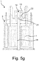
- the Figures 5a-5g illustrate a first variant of a method according to the invention for upgrading a standard NMR magnet system to a magnet system according to the invention; the resulting magnet system according to the invention corresponds to that in 1 embodiment shown.
- a conventional magnet system 50 is provided, which is used for NMR experiments with only one magnetic field or sample volume, as in Figure 5a shown ("standard NMR system").
- the magnet system 50 has a cryostat 2 with an RT casing 4 in which a main field magnet 7 is arranged in a cooled main coil container 6 .
- the cryostat 2 has a vertical RT bore 14 in which a first magnetic field can be generated with the main field magnet 7 at a first sample volume 16 .
- the RT bore 14 is bounded by an existing one-piece wall tube 52 .
- the cryostat 2 is accessible here at its upper axial end, see axis A, via a flange connection 17 which is closed with a flange cover 51 in order to be able to keep a vacuum 5 in the RT casing 4 during conventional operation of the magnet system 50 .
- a next step b) the flange cover 51 is now removed from the flange connection 17, cf. Figure 5b . If necessary, the interior of the RT casing 4 is first ventilated for this purpose. In the variant shown, the existing wall pipe 52 is also removed in this step.
- the Figure 5c shows the magnet system 50 opened in this way.
- the open flange connection 17 has a (round) flange opening 19 with a minimum inner diameter MID.
- the minimum inner diameter MID is measured transversely to the RT bore 14 or perpendicularly to axis A (also applies to all other diameters, see below).
- step c) an additional coil container 21 and a closure structure 20, here formed with a hood section 18, are assembled, cf. Figure 5d .
- the additional coil container 21 and the closure structure 20 are fixed to each other in a manner not shown and therefore form an assembly 53 that can be assembled as a whole.
- the additional coil case 21 has a maximum diameter DZSB (at least insofar as it is intended to engage axially in the flange opening 19).
- a new, one-piece wall tube 54 is then inserted into the magnet system 50, cf. Fig. 5f .
- This new wall tube 54 is longer than the previously removed wall tube (Bz. 52 in Figure 5b ).
- the retrofitting of the magnet system for 2-field NMR operation is complete; the Fig. 5g shows the retrofitted magnet system 1 according to the invention.
- a second magnetic field can now be set up with the additional field magnet 22 on a second sample volume 24 in the RT bore 14 .
- the new wall tube 54 is so long that it forms the RT bore 14 of the magnet system 1 continuously from the area of the main field magnet 7 or the lower end of the cryostat 2 to the additional field magnet 22 or the upper end of the hood section 18 .
- the Figures 6a-6g illustrate a second variant of a method according to the invention for upgrading a standard NMR magnet system to a magnet system according to the invention; the resulting magnet system according to the invention corresponds to that in 3 embodiment shown.
- the second variant of the method Figures 6a-6g similar to the first variant of Figures 5a-5g , so that only the essential differences are explained in more detail.
- a first step as in Figure 5a explains a conventional magnet system 50 that is set up for NMR experiments with only one magnetic field or sample volume, cf. Figure 6a .
- a step b) as already in Figure 5b explained, the flange cover 51 and the existing, one-piece wall pipe 52 of the RT bore are removed, cf. Figure 6b .
- the cryostat 2 is obtained with the flange connection 17 open, as already described in Figure 5c explained and in Figure 6c shown.
- the (round) flange opening 19 in turn has a (maximum) inside diameter MID.
- an insertion section 26 is mounted on the flange connection 17 and a new wall tube 55 is inserted into the cryostat 2 in any order, cf. Figure 6d .
- This new wall tube 55 is shorter than the removed wall tube (Bz. 52 in Figure 6b ).
- the new wall pipe 55 can be a spare part or it can also be obtained by shortening the removed wall pipe.
- the pot-shaped insert section 26 has an opening 26a for the RT bore in its bottom.
- the insertion section 26 is the largest component transversely to the axis A, which must be pushed into the flange opening 19, and therefore defines a maximum outer diameter DALL of all components to be inserted in this way. Since DALL is smaller than MID, the insertion section 26 can simply be pushed axially into the flange opening 19 and placed on the flange connection 17 and mounted.
- An assembly 56 comprising an additional vacuum container 25 and an additional coil container 21 contained therein with the additional magnet 22 is then installed, cf. Fig. 6f .
- the maximum outside diameter DZVB of the additional vacuum container is smaller than the minimum inside diameter IEA of the receiving area of the insertion section 26, so that the assembly 56 can be pushed axially into the insertion section 26.
- DZSB ⁇ MID and DZVB ⁇ MID as well.
- the auxiliary vacuum tank 25 and thus The assembly 56 also includes a second section 30 of a wall for the RT bore 14.
- the retrofit is complete and the magnet system 1 according to the invention is complete.
- the sections 29, 30 complement each other to form a complete wall or boundary of the RT bore 14.
- a first magnetic field can now be generated in the first sample volume 16 with the main field magnet 7, and in the second sample volume 24 with the additional field magnet 22 a second Magnetic field generated to perform 2-field NMR experiments.
- the assembly and disassembly of the assembly 56 and the auxiliary vacuum container 25 can be carried out without breaking a vacuum 5 inside the RT jacket 4 of the cryostat 2 .
Landscapes
- Physics & Mathematics (AREA)
- Condensed Matter Physics & Semiconductors (AREA)
- General Physics & Mathematics (AREA)
- Electromagnetism (AREA)
- Engineering & Computer Science (AREA)
- Power Engineering (AREA)
- Magnetic Resonance Imaging Apparatus (AREA)
- Containers, Films, And Cooling For Superconductive Devices (AREA)
Applications Claiming Priority (1)
| Application Number | Priority Date | Filing Date | Title |
|---|---|---|---|
| DE102020214887.2A DE102020214887B4 (de) | 2020-11-26 | 2020-11-26 | Magnetsystem zur Durchführung von 2-Feld-NMR-Experimenten und zugehöriges Nachrüstverfahren |
Publications (2)
| Publication Number | Publication Date |
|---|---|
| EP4006567A1 true EP4006567A1 (fr) | 2022-06-01 |
| EP4006567B1 EP4006567B1 (fr) | 2023-03-01 |
Family
ID=78676508
Family Applications (1)
| Application Number | Title | Priority Date | Filing Date |
|---|---|---|---|
| EP21208809.0A Active EP4006567B1 (fr) | 2020-11-26 | 2021-11-17 | Système magnétique destiné à la mise en oeuvre des expériences rmn à 2 champs et procédé de mise à niveau associé |
Country Status (3)
| Country | Link |
|---|---|
| US (1) | US11579224B2 (fr) |
| EP (1) | EP4006567B1 (fr) |
| DE (1) | DE102020214887B4 (fr) |
Families Citing this family (2)
| Publication number | Priority date | Publication date | Assignee | Title |
|---|---|---|---|---|
| PL442660A1 (pl) * | 2022-10-27 | 2024-04-29 | Uniwersytet Łódzki | Cewka do wytwarzania silnych pól magnetycznych i sposób wytwarzania cewki do wytwarzania silnych pól magnetycznych |
| EP4530651B1 (fr) * | 2023-09-26 | 2025-10-29 | Bruker France S.A.S. | Dispositif rmn à champs combinés et à commutation rapide pour 2fnmr |
Citations (5)
| Publication number | Priority date | Publication date | Assignee | Title |
|---|---|---|---|---|
| WO2002037132A1 (fr) | 2000-11-03 | 2002-05-10 | Amersham Health As | Procedes et dispositifs de dissolution de materiau solide hyperpolarise pour analyses en rmn |
| EP1747478B1 (fr) | 2004-05-18 | 2010-02-03 | Oxford Instruments Superconductivity Limited | APPAREIL ET MÉTHODE POUR EXÉCUTER DES MESURES DNP-NMR <i>IN VITRO</i> |
| US20130168576A1 (en) * | 2011-12-29 | 2013-07-04 | Bruker Biospin Gmbh | Device and method for rapid dynamic nuclear polarization |
| EP2146215B1 (fr) | 2008-07-18 | 2013-10-16 | Bruker BioSpin AG | Appareil d'exécution de mesures DNP-RMN doté d'un agencement de compensation et procédé de conception de l'agencement de compensation |
| EP3081954B1 (fr) | 2015-04-13 | 2018-07-25 | Bruker France S.A.S. | Procédé de résonance magnétique nucléaire avec deux champs magnétiques |
-
2020
- 2020-11-26 DE DE102020214887.2A patent/DE102020214887B4/de not_active Expired - Fee Related
-
2021
- 2021-11-16 US US17/527,735 patent/US11579224B2/en active Active
- 2021-11-17 EP EP21208809.0A patent/EP4006567B1/fr active Active
Patent Citations (6)
| Publication number | Priority date | Publication date | Assignee | Title |
|---|---|---|---|---|
| WO2002037132A1 (fr) | 2000-11-03 | 2002-05-10 | Amersham Health As | Procedes et dispositifs de dissolution de materiau solide hyperpolarise pour analyses en rmn |
| EP1747478B1 (fr) | 2004-05-18 | 2010-02-03 | Oxford Instruments Superconductivity Limited | APPAREIL ET MÉTHODE POUR EXÉCUTER DES MESURES DNP-NMR <i>IN VITRO</i> |
| EP2146215B1 (fr) | 2008-07-18 | 2013-10-16 | Bruker BioSpin AG | Appareil d'exécution de mesures DNP-RMN doté d'un agencement de compensation et procédé de conception de l'agencement de compensation |
| US20130168576A1 (en) * | 2011-12-29 | 2013-07-04 | Bruker Biospin Gmbh | Device and method for rapid dynamic nuclear polarization |
| US9279868B2 (en) | 2011-12-29 | 2016-03-08 | Bruker Biospin Gmbh | Device and method for rapid dynamic nuclear polarization |
| EP3081954B1 (fr) | 2015-04-13 | 2018-07-25 | Bruker France S.A.S. | Procédé de résonance magnétique nucléaire avec deux champs magnétiques |
Non-Patent Citations (1)
| Title |
|---|
| S. F. COUSIN ET AL., PHYS. CHEM. CHEM. PHYS., vol. 18, 2016, pages 33187 |
Also Published As
| Publication number | Publication date |
|---|---|
| DE102020214887A1 (de) | 2022-06-02 |
| DE102020214887B4 (de) | 2022-08-04 |
| US11579224B2 (en) | 2023-02-14 |
| EP4006567B1 (fr) | 2023-03-01 |
| US20220163610A1 (en) | 2022-05-26 |
Similar Documents
| Publication | Publication Date | Title |
|---|---|---|
| DE102008054152B3 (de) | NMR-MAS-Probenkopf mit integrierter Transportleitung für einen MAS-Rotor | |
| DE102016218000B3 (de) | Kryostatenanordnung mit einem Vakuumbehälter und einem zu kühlenden Objekt, mit evakuierbarem Hohlraum | |
| EP4006567B1 (fr) | Système magnétique destiné à la mise en oeuvre des expériences rmn à 2 champs et procédé de mise à niveau associé | |
| DE69926949T2 (de) | Offener, supraleitender Magnet mit Abschirmung | |
| DE69927197T2 (de) | Abgeschirmter und offener supraleitender Magnet | |
| DE102008037507B4 (de) | Magnetanordnung für eine Magnetresonanz-Bildgebungsvorrichtung | |
| DE68907621T2 (de) | Magnetgeraet verwendet in einer magnetischen resonanzabbildungsanordnung. | |
| DE102013201110B3 (de) | NMR-MAS-Probenkopf mit integrierter Transportleitung für einen MAS-Rotor | |
| DE69930487T2 (de) | Aufhängungseinheit für einen supraleitenden Magnet | |
| DE19947539B4 (de) | Gradientenspulenanordnung mit Dämpfung innerer mechanischer Schwingungen | |
| DE69929752T2 (de) | Heliumtank für supraleitenden Magnet mit offener Architektur für die bildgebende magnetische Resonanz | |
| DE102016000863A1 (de) | NMR-Sonde | |
| DE102013219453B3 (de) | DNP-Vorrichtung | |
| DE202004021683U1 (de) | NMR-Sonde mit einer inneren Quadratur-Erfassungsspule in Kombination mit einer spiralförmig gewundenen, äußeren Spule zur Bestrahlung | |
| EP3282269A1 (fr) | Appareil rmn pourvu des composants formant sondes, refroidis par l'intermédiaire d'un sas sous vide dans un cryostat d'un assemblage d'aimants supraconducteurs ainsi que procédé de montage et son démontage | |
| DE102015218019B4 (de) | Kryostat mit Magnetanordnung, die einen LTS-Bereich und einen HTS-Bereich umfasst | |
| DE102006018650B4 (de) | Supraleitende Magnetanordung mit vermindertem Wärmeeintrag in tiefkalte Bereiche | |
| DE102005044635B4 (de) | Einrichtung zur Magnetfelderzeugung und Magnetresonanzanlage | |
| DE102015208850A1 (de) | MAS-Stator mit Absaugvorrichtung | |
| DE102007049701B4 (de) | NMR-Messkopf mit mehreren Resonatorsystemen zur simultanen Vermessung mehrerer Messproben in einem gekoppelten Mode | |
| DE102012209754A1 (de) | Spuleneinrichtung für einen Kernspintomographen | |
| DE102019202001B3 (de) | MAS-Probenkopf mit thermisch isolierter Probenkammer | |
| EP3242141B1 (fr) | Agencement de cryostat et d'aimant et procédé de réglage passif | |
| EP3953724B1 (fr) | Ensemble de mesure à résonance magnétique nucléaire (rmn) à trou froid du cryostat | |
| DE4125655C2 (de) | Resonatoranordnung für die Elektronenspinresonanz-Spektroskopie |
Legal Events
| Date | Code | Title | Description |
|---|---|---|---|
| PUAI | Public reference made under article 153(3) epc to a published international application that has entered the european phase |
Free format text: ORIGINAL CODE: 0009012 |
|
| STAA | Information on the status of an ep patent application or granted ep patent |
Free format text: STATUS: THE APPLICATION HAS BEEN PUBLISHED |
|
| AK | Designated contracting states |
Kind code of ref document: A1 Designated state(s): AL AT BE BG CH CY CZ DE DK EE ES FI FR GB GR HR HU IE IS IT LI LT LU LV MC MK MT NL NO PL PT RO RS SE SI SK SM TR |
|
| STAA | Information on the status of an ep patent application or granted ep patent |
Free format text: STATUS: REQUEST FOR EXAMINATION WAS MADE |
|
| 17P | Request for examination filed |
Effective date: 20220802 |
|
| RBV | Designated contracting states (corrected) |
Designated state(s): AL AT BE BG CH CY CZ DE DK EE ES FI FR GB GR HR HU IE IS IT LI LT LU LV MC MK MT NL NO PL PT RO RS SE SI SK SM TR |
|
| GRAP | Despatch of communication of intention to grant a patent |
Free format text: ORIGINAL CODE: EPIDOSNIGR1 |
|
| STAA | Information on the status of an ep patent application or granted ep patent |
Free format text: STATUS: GRANT OF PATENT IS INTENDED |
|
| RIC1 | Information provided on ipc code assigned before grant |
Ipc: G01R 33/3875 20060101ALN20221021BHEP Ipc: G01R 33/44 20060101ALN20221021BHEP Ipc: G01R 33/62 20060101ALN20221021BHEP Ipc: G01R 33/3815 20060101ALI20221021BHEP Ipc: G01R 33/30 20060101AFI20221021BHEP |
|
| RIC1 | Information provided on ipc code assigned before grant |
Ipc: G01R 33/3875 20060101ALN20221116BHEP Ipc: G01R 33/44 20060101ALN20221116BHEP Ipc: G01R 33/62 20060101ALN20221116BHEP Ipc: G01R 33/3815 20060101ALI20221116BHEP Ipc: G01R 33/30 20060101AFI20221116BHEP |
|
| INTG | Intention to grant announced |
Effective date: 20221130 |
|
| GRAS | Grant fee paid |
Free format text: ORIGINAL CODE: EPIDOSNIGR3 |
|
| GRAA | (expected) grant |
Free format text: ORIGINAL CODE: 0009210 |
|
| STAA | Information on the status of an ep patent application or granted ep patent |
Free format text: STATUS: THE PATENT HAS BEEN GRANTED |
|
| AK | Designated contracting states |
Kind code of ref document: B1 Designated state(s): AL AT BE BG CH CY CZ DE DK EE ES FI FR GB GR HR HU IE IS IT LI LT LU LV MC MK MT NL NO PL PT RO RS SE SI SK SM TR |
|
| REG | Reference to a national code |
Ref country code: GB Ref legal event code: FG4D Free format text: NOT ENGLISH |
|
| REG | Reference to a national code |
Ref country code: CH Ref legal event code: EP Ref country code: AT Ref legal event code: REF Ref document number: 1551353 Country of ref document: AT Kind code of ref document: T Effective date: 20230315 |
|
| REG | Reference to a national code |
Ref country code: DE Ref legal event code: R096 Ref document number: 502021000467 Country of ref document: DE |
|
| REG | Reference to a national code |
Ref country code: IE Ref legal event code: FG4D Free format text: LANGUAGE OF EP DOCUMENT: GERMAN |
|
| REG | Reference to a national code |
Ref country code: LT Ref legal event code: MG9D |
|
| REG | Reference to a national code |
Ref country code: NL Ref legal event code: MP Effective date: 20230301 |
|
| PG25 | Lapsed in a contracting state [announced via postgrant information from national office to epo] |
Ref country code: RS Free format text: LAPSE BECAUSE OF FAILURE TO SUBMIT A TRANSLATION OF THE DESCRIPTION OR TO PAY THE FEE WITHIN THE PRESCRIBED TIME-LIMIT Effective date: 20230301 Ref country code: NO Free format text: LAPSE BECAUSE OF FAILURE TO SUBMIT A TRANSLATION OF THE DESCRIPTION OR TO PAY THE FEE WITHIN THE PRESCRIBED TIME-LIMIT Effective date: 20230601 Ref country code: LV Free format text: LAPSE BECAUSE OF FAILURE TO SUBMIT A TRANSLATION OF THE DESCRIPTION OR TO PAY THE FEE WITHIN THE PRESCRIBED TIME-LIMIT Effective date: 20230301 Ref country code: LT Free format text: LAPSE BECAUSE OF FAILURE TO SUBMIT A TRANSLATION OF THE DESCRIPTION OR TO PAY THE FEE WITHIN THE PRESCRIBED TIME-LIMIT Effective date: 20230301 Ref country code: HR Free format text: LAPSE BECAUSE OF FAILURE TO SUBMIT A TRANSLATION OF THE DESCRIPTION OR TO PAY THE FEE WITHIN THE PRESCRIBED TIME-LIMIT Effective date: 20230301 Ref country code: ES Free format text: LAPSE BECAUSE OF FAILURE TO SUBMIT A TRANSLATION OF THE DESCRIPTION OR TO PAY THE FEE WITHIN THE PRESCRIBED TIME-LIMIT Effective date: 20230301 |
|
| PG25 | Lapsed in a contracting state [announced via postgrant information from national office to epo] |
Ref country code: SE Free format text: LAPSE BECAUSE OF FAILURE TO SUBMIT A TRANSLATION OF THE DESCRIPTION OR TO PAY THE FEE WITHIN THE PRESCRIBED TIME-LIMIT Effective date: 20230301 Ref country code: PL Free format text: LAPSE BECAUSE OF FAILURE TO SUBMIT A TRANSLATION OF THE DESCRIPTION OR TO PAY THE FEE WITHIN THE PRESCRIBED TIME-LIMIT Effective date: 20230301 Ref country code: NL Free format text: LAPSE BECAUSE OF FAILURE TO SUBMIT A TRANSLATION OF THE DESCRIPTION OR TO PAY THE FEE WITHIN THE PRESCRIBED TIME-LIMIT Effective date: 20230301 Ref country code: GR Free format text: LAPSE BECAUSE OF FAILURE TO SUBMIT A TRANSLATION OF THE DESCRIPTION OR TO PAY THE FEE WITHIN THE PRESCRIBED TIME-LIMIT Effective date: 20230602 Ref country code: FI Free format text: LAPSE BECAUSE OF FAILURE TO SUBMIT A TRANSLATION OF THE DESCRIPTION OR TO PAY THE FEE WITHIN THE PRESCRIBED TIME-LIMIT Effective date: 20230301 |
|
| PG25 | Lapsed in a contracting state [announced via postgrant information from national office to epo] |
Ref country code: SM Free format text: LAPSE BECAUSE OF FAILURE TO SUBMIT A TRANSLATION OF THE DESCRIPTION OR TO PAY THE FEE WITHIN THE PRESCRIBED TIME-LIMIT Effective date: 20230301 Ref country code: RO Free format text: LAPSE BECAUSE OF FAILURE TO SUBMIT A TRANSLATION OF THE DESCRIPTION OR TO PAY THE FEE WITHIN THE PRESCRIBED TIME-LIMIT Effective date: 20230301 Ref country code: PT Free format text: LAPSE BECAUSE OF FAILURE TO SUBMIT A TRANSLATION OF THE DESCRIPTION OR TO PAY THE FEE WITHIN THE PRESCRIBED TIME-LIMIT Effective date: 20230703 Ref country code: EE Free format text: LAPSE BECAUSE OF FAILURE TO SUBMIT A TRANSLATION OF THE DESCRIPTION OR TO PAY THE FEE WITHIN THE PRESCRIBED TIME-LIMIT Effective date: 20230301 Ref country code: CZ Free format text: LAPSE BECAUSE OF FAILURE TO SUBMIT A TRANSLATION OF THE DESCRIPTION OR TO PAY THE FEE WITHIN THE PRESCRIBED TIME-LIMIT Effective date: 20230301 |
|
| PG25 | Lapsed in a contracting state [announced via postgrant information from national office to epo] |
Ref country code: SK Free format text: LAPSE BECAUSE OF FAILURE TO SUBMIT A TRANSLATION OF THE DESCRIPTION OR TO PAY THE FEE WITHIN THE PRESCRIBED TIME-LIMIT Effective date: 20230301 Ref country code: IS Free format text: LAPSE BECAUSE OF FAILURE TO SUBMIT A TRANSLATION OF THE DESCRIPTION OR TO PAY THE FEE WITHIN THE PRESCRIBED TIME-LIMIT Effective date: 20230701 |
|
| REG | Reference to a national code |
Ref country code: DE Ref legal event code: R097 Ref document number: 502021000467 Country of ref document: DE |
|
| PLBE | No opposition filed within time limit |
Free format text: ORIGINAL CODE: 0009261 |
|
| STAA | Information on the status of an ep patent application or granted ep patent |
Free format text: STATUS: NO OPPOSITION FILED WITHIN TIME LIMIT |
|
| P01 | Opt-out of the competence of the unified patent court (upc) registered |
Effective date: 20231221 |
|
| PG25 | Lapsed in a contracting state [announced via postgrant information from national office to epo] |
Ref country code: SI Free format text: LAPSE BECAUSE OF FAILURE TO SUBMIT A TRANSLATION OF THE DESCRIPTION OR TO PAY THE FEE WITHIN THE PRESCRIBED TIME-LIMIT Effective date: 20230301 Ref country code: DK Free format text: LAPSE BECAUSE OF FAILURE TO SUBMIT A TRANSLATION OF THE DESCRIPTION OR TO PAY THE FEE WITHIN THE PRESCRIBED TIME-LIMIT Effective date: 20230301 |
|
| 26N | No opposition filed |
Effective date: 20231204 |
|
| PG25 | Lapsed in a contracting state [announced via postgrant information from national office to epo] |
Ref country code: IT Free format text: LAPSE BECAUSE OF FAILURE TO SUBMIT A TRANSLATION OF THE DESCRIPTION OR TO PAY THE FEE WITHIN THE PRESCRIBED TIME-LIMIT Effective date: 20230301 |
|
| PG25 | Lapsed in a contracting state [announced via postgrant information from national office to epo] |
Ref country code: MC Free format text: LAPSE BECAUSE OF FAILURE TO SUBMIT A TRANSLATION OF THE DESCRIPTION OR TO PAY THE FEE WITHIN THE PRESCRIBED TIME-LIMIT Effective date: 20230301 |
|
| PG25 | Lapsed in a contracting state [announced via postgrant information from national office to epo] |
Ref country code: LU Free format text: LAPSE BECAUSE OF NON-PAYMENT OF DUE FEES Effective date: 20231117 |
|
| PG25 | Lapsed in a contracting state [announced via postgrant information from national office to epo] |
Ref country code: MC Free format text: LAPSE BECAUSE OF FAILURE TO SUBMIT A TRANSLATION OF THE DESCRIPTION OR TO PAY THE FEE WITHIN THE PRESCRIBED TIME-LIMIT Effective date: 20230301 Ref country code: LU Free format text: LAPSE BECAUSE OF NON-PAYMENT OF DUE FEES Effective date: 20231117 |
|
| REG | Reference to a national code |
Ref country code: BE Ref legal event code: MM Effective date: 20231130 |
|
| REG | Reference to a national code |
Ref country code: IE Ref legal event code: MM4A |
|
| PG25 | Lapsed in a contracting state [announced via postgrant information from national office to epo] |
Ref country code: IE Free format text: LAPSE BECAUSE OF NON-PAYMENT OF DUE FEES Effective date: 20231117 |
|
| PG25 | Lapsed in a contracting state [announced via postgrant information from national office to epo] |
Ref country code: BE Free format text: LAPSE BECAUSE OF NON-PAYMENT OF DUE FEES Effective date: 20231130 |
|
| PG25 | Lapsed in a contracting state [announced via postgrant information from national office to epo] |
Ref country code: IE Free format text: LAPSE BECAUSE OF NON-PAYMENT OF DUE FEES Effective date: 20231117 Ref country code: BE Free format text: LAPSE BECAUSE OF NON-PAYMENT OF DUE FEES Effective date: 20231130 |
|
| PG25 | Lapsed in a contracting state [announced via postgrant information from national office to epo] |
Ref country code: BG Free format text: LAPSE BECAUSE OF FAILURE TO SUBMIT A TRANSLATION OF THE DESCRIPTION OR TO PAY THE FEE WITHIN THE PRESCRIBED TIME-LIMIT Effective date: 20230301 |
|
| PG25 | Lapsed in a contracting state [announced via postgrant information from national office to epo] |
Ref country code: BG Free format text: LAPSE BECAUSE OF FAILURE TO SUBMIT A TRANSLATION OF THE DESCRIPTION OR TO PAY THE FEE WITHIN THE PRESCRIBED TIME-LIMIT Effective date: 20230301 |
|
| PG25 | Lapsed in a contracting state [announced via postgrant information from national office to epo] |
Ref country code: CY Free format text: LAPSE BECAUSE OF FAILURE TO SUBMIT A TRANSLATION OF THE DESCRIPTION OR TO PAY THE FEE WITHIN THE PRESCRIBED TIME-LIMIT; INVALID AB INITIO Effective date: 20211117 |
|
| REG | Reference to a national code |
Ref country code: CH Ref legal event code: U11 Free format text: ST27 STATUS EVENT CODE: U-0-0-U10-U11 (AS PROVIDED BY THE NATIONAL OFFICE) Effective date: 20251201 |
|
| PG25 | Lapsed in a contracting state [announced via postgrant information from national office to epo] |
Ref country code: TR Free format text: LAPSE BECAUSE OF FAILURE TO SUBMIT A TRANSLATION OF THE DESCRIPTION OR TO PAY THE FEE WITHIN THE PRESCRIBED TIME-LIMIT Effective date: 20230301 |
|
| PGFP | Annual fee paid to national office [announced via postgrant information from national office to epo] |
Ref country code: DE Payment date: 20251118 Year of fee payment: 5 |
|
| PGFP | Annual fee paid to national office [announced via postgrant information from national office to epo] |
Ref country code: GB Payment date: 20251120 Year of fee payment: 5 |
|
| PGFP | Annual fee paid to national office [announced via postgrant information from national office to epo] |
Ref country code: AT Payment date: 20260113 Year of fee payment: 5 |
|
| PGFP | Annual fee paid to national office [announced via postgrant information from national office to epo] |
Ref country code: FR Payment date: 20251125 Year of fee payment: 5 |
|
| PGFP | Annual fee paid to national office [announced via postgrant information from national office to epo] |
Ref country code: CH Payment date: 20251201 Year of fee payment: 5 |
|
| PG25 | Lapsed in a contracting state [announced via postgrant information from national office to epo] |
Ref country code: HU Free format text: LAPSE BECAUSE OF FAILURE TO SUBMIT A TRANSLATION OF THE DESCRIPTION OR TO PAY THE FEE WITHIN THE PRESCRIBED TIME-LIMIT; INVALID AB INITIO Effective date: 20211117 |