EP4006586A1 - Abstandsmessvorrichtung, abstandsmesssystem und einstellverfahren für eine abstandsmessvorrichtung - Google Patents
Abstandsmessvorrichtung, abstandsmesssystem und einstellverfahren für eine abstandsmessvorrichtung Download PDFInfo
- Publication number
- EP4006586A1 EP4006586A1 EP20848464.2A EP20848464A EP4006586A1 EP 4006586 A1 EP4006586 A1 EP 4006586A1 EP 20848464 A EP20848464 A EP 20848464A EP 4006586 A1 EP4006586 A1 EP 4006586A1
- Authority
- EP
- European Patent Office
- Prior art keywords
- light source
- modulation frequency
- distance measuring
- measuring device
- light
- Prior art date
- Legal status (The legal status is an assumption and is not a legal conclusion. Google has not performed a legal analysis and makes no representation as to the accuracy of the status listed.)
- Pending
Links
Images


Classifications
-
- G—PHYSICS
- G01—MEASURING; TESTING
- G01C—MEASURING DISTANCES, LEVELS OR BEARINGS; SURVEYING; NAVIGATION; GYROSCOPIC INSTRUMENTS; PHOTOGRAMMETRY OR VIDEOGRAMMETRY
- G01C3/00—Measuring distances in line of sight; Optical rangefinders
- G01C3/02—Details
- G01C3/06—Use of electric means to obtain final indication
- G01C3/08—Use of electric radiation detectors
-
- G—PHYSICS
- G01—MEASURING; TESTING
- G01S—RADIO DIRECTION-FINDING; RADIO NAVIGATION; DETERMINING DISTANCE OR VELOCITY BY USE OF RADIO WAVES; LOCATING OR PRESENCE-DETECTING BY USE OF THE REFLECTION OR RERADIATION OF RADIO WAVES; ANALOGOUS ARRANGEMENTS USING OTHER WAVES
- G01S7/00—Details of systems according to groups G01S13/00, G01S15/00, G01S17/00
- G01S7/48—Details of systems according to groups G01S13/00, G01S15/00, G01S17/00 of systems according to group G01S17/00
- G01S7/483—Details of pulse systems
- G01S7/486—Receivers
- G01S7/4865—Time delay measurement, e.g. time-of-flight measurement, time of arrival measurement or determining the exact position of a peak
-
- G—PHYSICS
- G01—MEASURING; TESTING
- G01S—RADIO DIRECTION-FINDING; RADIO NAVIGATION; DETERMINING DISTANCE OR VELOCITY BY USE OF RADIO WAVES; LOCATING OR PRESENCE-DETECTING BY USE OF THE REFLECTION OR RERADIATION OF RADIO WAVES; ANALOGOUS ARRANGEMENTS USING OTHER WAVES
- G01S17/00—Systems using the reflection or reradiation of electromagnetic waves other than radio waves, e.g. lidar systems
- G01S17/003—Bistatic lidar systems; Multistatic lidar systems
-
- G—PHYSICS
- G01—MEASURING; TESTING
- G01S—RADIO DIRECTION-FINDING; RADIO NAVIGATION; DETERMINING DISTANCE OR VELOCITY BY USE OF RADIO WAVES; LOCATING OR PRESENCE-DETECTING BY USE OF THE REFLECTION OR RERADIATION OF RADIO WAVES; ANALOGOUS ARRANGEMENTS USING OTHER WAVES
- G01S17/00—Systems using the reflection or reradiation of electromagnetic waves other than radio waves, e.g. lidar systems
- G01S17/02—Systems using the reflection of electromagnetic waves other than radio waves
- G01S17/06—Systems determining position data of a target
- G01S17/08—Systems determining position data of a target for measuring distance only
- G01S17/10—Systems determining position data of a target for measuring distance only using transmission of interrupted, pulse-modulated waves
-
- G—PHYSICS
- G01—MEASURING; TESTING
- G01S—RADIO DIRECTION-FINDING; RADIO NAVIGATION; DETERMINING DISTANCE OR VELOCITY BY USE OF RADIO WAVES; LOCATING OR PRESENCE-DETECTING BY USE OF THE REFLECTION OR RERADIATION OF RADIO WAVES; ANALOGOUS ARRANGEMENTS USING OTHER WAVES
- G01S17/00—Systems using the reflection or reradiation of electromagnetic waves other than radio waves, e.g. lidar systems
- G01S17/02—Systems using the reflection of electromagnetic waves other than radio waves
- G01S17/06—Systems determining position data of a target
- G01S17/08—Systems determining position data of a target for measuring distance only
- G01S17/32—Systems determining position data of a target for measuring distance only using transmission of continuous waves, whether amplitude-, frequency-, or phase-modulated, or unmodulated
- G01S17/36—Systems determining position data of a target for measuring distance only using transmission of continuous waves, whether amplitude-, frequency-, or phase-modulated, or unmodulated with phase comparison between the received signal and the contemporaneously transmitted signal
-
- G—PHYSICS
- G01—MEASURING; TESTING
- G01S—RADIO DIRECTION-FINDING; RADIO NAVIGATION; DETERMINING DISTANCE OR VELOCITY BY USE OF RADIO WAVES; LOCATING OR PRESENCE-DETECTING BY USE OF THE REFLECTION OR RERADIATION OF RADIO WAVES; ANALOGOUS ARRANGEMENTS USING OTHER WAVES
- G01S7/00—Details of systems according to groups G01S13/00, G01S15/00, G01S17/00
- G01S7/003—Transmission of data between radar, sonar or lidar systems and remote stations
-
- G—PHYSICS
- G01—MEASURING; TESTING
- G01S—RADIO DIRECTION-FINDING; RADIO NAVIGATION; DETERMINING DISTANCE OR VELOCITY BY USE OF RADIO WAVES; LOCATING OR PRESENCE-DETECTING BY USE OF THE REFLECTION OR RERADIATION OF RADIO WAVES; ANALOGOUS ARRANGEMENTS USING OTHER WAVES
- G01S7/00—Details of systems according to groups G01S13/00, G01S15/00, G01S17/00
- G01S7/48—Details of systems according to groups G01S13/00, G01S15/00, G01S17/00 of systems according to group G01S17/00
- G01S7/491—Details of non-pulse systems
- G01S7/4911—Transmitters
-
- G—PHYSICS
- G01—MEASURING; TESTING
- G01S—RADIO DIRECTION-FINDING; RADIO NAVIGATION; DETERMINING DISTANCE OR VELOCITY BY USE OF RADIO WAVES; LOCATING OR PRESENCE-DETECTING BY USE OF THE REFLECTION OR RERADIATION OF RADIO WAVES; ANALOGOUS ARRANGEMENTS USING OTHER WAVES
- G01S7/00—Details of systems according to groups G01S13/00, G01S15/00, G01S17/00
- G01S7/48—Details of systems according to groups G01S13/00, G01S15/00, G01S17/00 of systems according to group G01S17/00
- G01S7/491—Details of non-pulse systems
- G01S7/4912—Receivers
- G01S7/4915—Time delay measurement, e.g. operational details for pixel components; Phase measurement
-
- G—PHYSICS
- G01—MEASURING; TESTING
- G01S—RADIO DIRECTION-FINDING; RADIO NAVIGATION; DETERMINING DISTANCE OR VELOCITY BY USE OF RADIO WAVES; LOCATING OR PRESENCE-DETECTING BY USE OF THE REFLECTION OR RERADIATION OF RADIO WAVES; ANALOGOUS ARRANGEMENTS USING OTHER WAVES
- G01S7/00—Details of systems according to groups G01S13/00, G01S15/00, G01S17/00
- G01S7/48—Details of systems according to groups G01S13/00, G01S15/00, G01S17/00 of systems according to group G01S17/00
- G01S7/497—Means for monitoring or calibrating
-
- G—PHYSICS
- G01—MEASURING; TESTING
- G01S—RADIO DIRECTION-FINDING; RADIO NAVIGATION; DETERMINING DISTANCE OR VELOCITY BY USE OF RADIO WAVES; LOCATING OR PRESENCE-DETECTING BY USE OF THE REFLECTION OR RERADIATION OF RADIO WAVES; ANALOGOUS ARRANGEMENTS USING OTHER WAVES
- G01S17/00—Systems using the reflection or reradiation of electromagnetic waves other than radio waves, e.g. lidar systems
- G01S17/88—Lidar systems specially adapted for specific applications
- G01S17/89—Lidar systems specially adapted for specific applications for mapping or imaging
- G01S17/894—Three-dimensional [3D] imaging with simultaneous measurement of time-of-flight at a two-dimensional [2D] array of receiver pixels, e.g. time-of-flight cameras or flash lidar
Definitions
- the present disclosure relates to a distance measuring device, a distance measuring system, and a method of adjusting a distance measuring device.
- the ToF method is a method of irradiating an object with light using a light source, receiving reflected light by a ToF sensor, and measuring a distance to the object by analyzing a light reception result.
- Patent Literature 1 there is also known a technique of irradiating an object with light from a light source separate from the ToF sensor, receiving reflected light by the ToF sensor, and measuring a distance to the object. (See, for example, Patent Literature 1.)
- Patent Literature 1 JP 2018-31607 A
- a light source and a ToF sensor are separately configured, a light source clock for the light source and a sensor clock for the ToF sensor are separate. Therefore, a modulation frequency of the light source and a modulation frequency of the ToF sensor are not always synchronized, and the frequencies may be deviated. Then, in a case where the modulation frequency of the ToF sensor deviates from the modulation frequency of the light source, an error may occur in a distance measurement result.
- the present disclosure proposes a distance measuring device, a distance measuring system, and a method of adjusting the distance measuring device capable of matching the modulation frequency of the ToF sensor with the modulation frequency of the light source.
- the distance measuring device includes a ToF (time of flight) sensor, a distance calculation unit, a mode switching unit, and an estimation unit.
- the ToF sensor has a device-specific clock that is the sensor clock for controlling the photographing timing and is different from the light source clock for controlling the light-emitting timing of the light source.
- the ToF sensor reflects the emission light of the light source emitting the pulse light on the surface of the object to perform photographing.
- the distance calculation unit calculates the distance to the object based on the image data captured by the ToF sensor.
- the mode switching unit switches the operation mode of the ToF sensor.
- the estimation unit estimates the modulation frequency of the light source generated from the light source clock based on a plurality pieces of image data captured by switching the operation mode by the mode switching unit.
- a modulation frequency of a ToF sensor can be matched with a modulation frequency of a light source.
- effects described herein are not necessarily limited, and may be any of the effects described in the present disclosure.
- the ToF method is a method of irradiating an object with light using a light source, receiving reflected light by a ToF sensor, and measuring a distance to the object by analyzing a light reception result.
- a modulation frequency of the light source and a modulation frequency of the ToF sensor are not always synchronized, and the frequencies may be deviated. Then, in a case where the modulation frequency of the ToF sensor deviates from the modulation frequency of the light source, an error may occur in a distance measurement result.
- the present disclosure relates to a technique for measuring a distance using light. Therefore, in order to facilitate understanding of each embodiment of the present disclosure, a distance measurement method applicable to each embodiment will be described with reference to FIG. 1 to FIG. 5 .
- the ToF method is a method of irradiating an object with emission light and analyzing its reflected light to measure a distance (depth) to the object or a shape of the object.
- the following description does not particularly mention a three-dimensional shape measurement process, but the three-dimensional shape of the object can be measured by measuring a distance of an object surface over the entire object surface.
- FIG. 1 to FIG. 5 are diagrams illustrating an outline of a distance measurement process using the ToF method.
- a distance measuring system 1 according to each embodiment includes a light source 2 and a distance measuring device 3. Then, in the distance measuring system 1, emission light L1 from the light source 2 is reflected by an object 4, and reflected light L2 is received by the distance measuring device 3.
- a distance (depth) d from the distance measuring device 3 to the object 4 can be calculated using the following Expression (1) by measuring time ⁇ t until the emission light L1 from the light source 2 is reflected by the object 4 and enters the distance measuring device 3.
- ⁇ t time for light reciprocation
- d a one-way distance, and thus is divided by 2.
- d c / 2 ⁇ ⁇ t c : Light velocity 2.9979 ⁇ 10 8 m / sec
- the distance measuring system 1 since it is not easy to directly measure the time ⁇ t, the distance measuring system 1 according to each embodiment emits pulse light from the light source 2 as the emission light L1 as illustrated in FIG. 2 . Then, as illustrated in FIG. 3 , a phase ⁇ of the pulse light returned to the distance measuring device 3 (light-receiving pattern) as the reflected light L2, based on the pulse light from the light source 2 (light-emitting pattern), is converted into the time ⁇ t.
- the time ⁇ t can be calculated using the following Expression (2).
- ⁇ t 1 / f ⁇ ⁇ / 2 ⁇
- a distance d from the distance measuring device 3 to the object 4 can be calculated using the following Expression (3).
- d c ⁇ / 4 ⁇ f
- the distance measuring device 3 includes a ToF sensor 23 ( FIG. 6 ).
- the ToF sensor 23 has a function in which each pixel repeats ON/OFF at a high speed and accumulates electric charge only during an ON period.
- an ON/OFF execution timing is sequentially switched to analyze accumulated charge at each timing.
- the ToF sensor 23 of the distance measuring device 3 sequentially executes these four switching patterns to acquire a received light quantity at each changed light-receiving timing. In other words, four types of received light quantities with different accumulated phases and charges corresponding to the received light quantities are acquired.
- the phase ⁇ needed for calculating the distance d to the object by applying the above-described Expression (3) is a phase of pulse light received by the distance measuring device 3 ((b) light-receiving pattern) with reference to the pulse light emitted from the light source 2.
- This phase ⁇ can be calculated using the following Expression (4).
- ⁇ Arctan Q 90 ⁇ Q 270 / Q 180 ⁇ Q 0
- the distance d from the distance measuring device 3 to the object 4 can be calculated by inputting the phase ⁇ calculated by the above Expression (4) in the above Expression (3).
- FIG. 5 is a diagram illustrating image data captured by the ToF sensor 23 from left to right according to a time axis.
- the accumulated charge of a captured image is referred to as a "component" in phase settings in which a phase difference between a pulse light-emitting pattern and a drive pattern of a sensor pixel is 0 degrees, 90 degrees, 180 degrees, and 270 degrees.
- the captured images with the phase settings whose phase deviation amounts from the light-emitting pattern (pulse) are 0 degrees, 90 degrees, 180 degrees, and 270 degrees are sequentially and repeatedly captured.
- a set of combinations of components of phase settings of 0 degrees, 90 degrees, 180 degrees, and 270 degrees is referred to as a "frame".
- one frame has information regarding the accumulated charges (components) Q 0 , Q 90 , Q 180 , and Q 270 of the captured images in phase settings whose phase deviation amounts from the light-emitting pattern (pulse) are 0 degrees, 90 degrees, 180 degrees, and 270 degrees.
- phase image an image obtained using Expression (4) is referred to as a "phase image”.
- time between the components is set to be shorter than time between the frames.
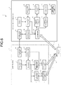
- FIG. 6 is a block diagram illustrating a configuration example of the distance measuring system 1 according to the first embodiment of the present disclosure.
- the distance measuring system 1 includes the light source 2 and the distance measuring device 3.
- the light source 2 and the distance measuring device 3 are configured separately.
- the light source 2 and the distance measuring device 3 do not necessarily need to be configured separately, and may be configured integrally.
- the light source 2 emits pulse light having a predetermined modulation frequency to the object 4 as the emission light L1.
- the light source 2 includes a light source clock 11, a phase locked loop (PLL) circuit 12, a plurality of delay adjustment units 13a, 13b, and so on, a plurality of light source units 14a, 14b, and so on, a control unit 15, and a communication unit 16.
- PLL phase locked loop
- the light source clock 11 generates a clock signal having a predetermined frequency f CL1 .
- the PLL circuit 12 multiplies by a constant number the frequency f CL1 of the clock signal generated by the light source clock 11 to generate a pulse signal having a predetermined modulation frequency f L .
- C L set in the PLL circuit 12 is also referred to as a "PLL coefficient".
- the delay adjustment units 13a, 13b, and so on control a delay amount of a light-emitting timing in the light source units 14a, 14b, and so on according to a length of wiring from the light source clock 11 to corresponding light source units 14a, 14b, and so on.
- the light source units 14a, 14b, and so on emit the pulse light corresponding to a pulse signal generated by the PLL circuit 12 as the emission light L1.
- the light source units 14a, 14b, and so on emit the pulse light having the above-described modulation frequency f L .
- the light source units 14a, 14b, and so on are configured with, for example, a laser diode such as a vertical cavity surface emitting laser (VCSEL). Note that the light source units 14a, 14b, and so on are not limited to the VCSEL, and a laser diode array or the like in which laser diodes are aligned may be used.
- a laser diode such as a vertical cavity surface emitting laser (VCSEL).
- VCSEL vertical cavity surface emitting laser
- the control unit 15 controls the entire operation of the light source 2 according to, for example, a program incorporated in advance.
- the control unit 15 can switch an operation mode of the light source 2 by controlling the PLL circuit 12 and the light source units 14a, 14b, and so on.
- control unit 15 can control the modulation frequency f L of the emission light L1 by controlling the PLL coefficient C L of the PLL circuit 12. Furthermore, the control unit 15 can control ON/OFF of the emission light L1 by controlling the light source units 14a, 14b, and so on.
- the communication unit 16 transmits and receives various types of information to and from a communication unit 31 of the distance measuring device 3.
- a communication method used between the communication unit 16 and the communication unit 31 any method in a wired or wireless manner can be applied (e.g., a local area network (LAN), WiFi (registered trademark), and Bluetooth (registered trademark)).
- LAN local area network
- WiFi registered trademark
- Bluetooth registered trademark
- the light source 2 and the distance measuring device 3 are synchronized timewise, and the light-emitting timing and the light-receiving timing are determined in advance.
- precision time protocol PTP
- PTP precision time protocol
- the distance measuring device 3 measures the distance d (see FIG. 1 ) to the object 4 using the emission light from the plurality of light source units 14a, 14b, and so on.
- the distance measuring device 3 includes a sensor clock 21, a PLL circuit 22, the ToF sensor 23, a phase calculation unit 24, a storage unit 25, a distance calculation unit 26, a moving subject detection unit 27, an estimation unit 28, an adjustment unit 29, a control unit 30, and the communication unit 31.
- the control unit 30 is an example of a mode switching unit.
- the sensor clock 21 generates the clock signal having a predetermined frequency f CL2 .
- the PLL circuit 22 multiplies by a constant number the frequency f CL2 of the clock signal generated by the sensor clock 21 to generate a pulse signal having a predetermined modulation frequency f s .
- the ToF sensor 23 receives the reflected light L2 from the plurality of light source units 14a, 14b, and so on at different light-receiving timings to acquire image data in which the different light-receiving timings are set.
- the ToF sensor 23 acquires the frame including a plurality of components Q 0 , Q 90 , Q 180 , and Q 270 .
- the sensor clock 21, the pulse signal of the modulation frequency f S generated using the PLL circuit 22, and the control unit 30 determine the light-receiving timing of the ToF sensor 23.
- the control unit 30 exposes the ToF sensor 23 in accordance with a predetermined light-emitting timing.
- the phase calculation unit 24 calculates, using the above Expression (4), the phase ⁇ from the data of the plurality of components Q 0 , Q 90 , Q 180 , and Q 270 acquired by the ToF sensor 23.
- the phase calculation unit 24 calculates the phase ⁇ for each frame.
- the storage unit 25 stores a frame image including the component captured by the ToF sensor 23 and data of the phase ⁇ calculated by the phase calculation unit 24.
- the distance calculation unit 26 calculates the distance d of the object 4 to be measured from data of a difference in the phase images of the plurality of light sources stored in the storage unit 25, using the method described in Patent Literature 1.
- the distance d is a distance from the distance measuring device 3 to a surface of the object 4.
- the moving subject detection unit 27 detects a moving subject from an image captured by the ToF sensor 23.
- the estimation unit 28 estimates the modulation frequency f L of the light source 2.
- the adjustment unit 29 adjusts the modulation frequency f s of the distance measuring device 3 based on the modulation frequency f L of the light source 2 estimated by the estimation unit 28. Details of an estimation process of the modulation frequency f L and an adjustment process of the modulation frequency f s will be described later.
- the control unit 30 controls the entire operation of the distance measuring device 3 according to, for example, a program incorporated in advance.
- the control unit 30 can switch an operation mode of the distance measuring device 3 by controlling the PLL circuit 22 and the ToF sensor 23.
- control unit 30 can control the light-receiving timing of the ToF sensor 23 by controlling the PLL coefficient C s of the PLL circuit 22. Furthermore, the control unit 30 can control ON/OFF of reception of the reflected light L2 by controlling the ToF sensor 23.
- the communication unit 31 synchronizes time of the system with the communication unit 16 of the light source 2, and transmits and receives various types of information. Examples of the various types of information include the light-emitting timing.
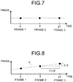
- FIG. 7 is a diagram illustrating a change in the phase ⁇ of each frame in a case where there is no deviation between the modulation frequency f L of the light source 2 and the modulation frequency f s of the distance measuring device 3.
- the plurality of light source units 14a, 14b, and so on are employed to measure the distance d using an external light source. Since the plurality of external light source units 14a, 14b, and so on are driven by the same clock, the modulation frequency matches with modulation frequencies of other light sources by synchronizing the modulation frequency with any one of the plurality of external light source units.
- the plurality of light sources are received by, for example, the ToF sensor 23 in a time division manner (switched for each frame).
- one light source unit operates without any problem for the main point (synchronization of modulation frequencies) of the present disclosure.
- FIG. 8 is a diagram illustrating a change in the phase ⁇ when there is a deviation between the modulation frequency f L of the light source 2 and the modulation frequency f s of the distance measuring device 3.
- a deviation amount ⁇ f between the modulation frequency f L and the modulation frequency f s can be calculated by the following method based on a deviation amount ⁇ of the phase ⁇ between adjacent frames (e.g., frame 2 and frame 3).
- the estimation unit 28 can calculate the deviation amount ⁇ f between the modulation frequency f L and the modulation frequency f s by using the following Expression (6).
- the adjustment unit 29 can adjust a new modulation frequency f s (N) of the distance measuring device 3 by using the following Expression (7) .
- the distance d can be accurately calculated.
- FIG. 9 is a diagram illustrating a change in the phase difference ⁇ when there is a large deviation between the modulation frequency f L of the light source 2 and the modulation frequency f S of the distance measuring device 3.
- a value of the phase difference ⁇ in each frame may be the same as that of the example in FIG. 8 .
- the deviation amount ⁇ f between the modulation frequency f L of the light source 2 and the modulation frequency f s of the distance measuring device 3 cannot be distinguished between ⁇ f (Hz), ⁇ f ⁇ 30 (Hz), ⁇ f ⁇ 60 (Hz), and so on.
- the deviation amount ⁇ f between the modulation frequency f L of the light source 2 and the modulation frequency f s of the distance measuring device 3 is accurately obtained.
- FIG. 10 is a diagram illustrating a first photographing process according to the first embodiment of the present disclosure.
- the control unit 30 sets the operation mode of the distance measuring device 3 in accordance with the operation mode of the light source 2 communicated in advance by the communication unit 31. Specifically, the operation modes are set such that the frame rates of the light source 2 and the distance measuring device 3 become a predetermined frame rate F 1 .
- the operation mode may be set by adjusting driving of the ToF sensor 23 using the setting of the light source 2 as a master, as described above, or may be set by another method.
- the setting of the distance measuring device 3 may be used as the master, and the operation mode of the distance measuring device 3 may be set using the light source 2 as a slave.
- the operation mode of the distance measuring device 3 may be set by switching the operation modes of both the light source 2 and the distance measuring device 3 at predetermined time. Note that, in this case, communication between the light source 2 and the distance measuring device 3 becomes unnecessary.
- the ToF sensor 23 captures the object 4 to acquire image data. Then, the phase calculation unit 24 calculates the phase ⁇ of the image data acquired for each frame.
- the estimation unit 28 calculates a deviation amount ⁇ 1 of the phase ⁇ between the adjacent frames, and then calculates a frequency deviation amount ⁇ f 1 from the deviation amount ⁇ 1 , using the following Expression (8).
- ⁇ f 1 ⁇ ⁇ 1 ⁇ F 1 / 2 ⁇
- a true deviation amount ⁇ f GT is a true deviation amount between the modulation frequency f L of the light source 2 and the modulation frequency f s of the distance measuring device 3
- a value of the true deviation amount ⁇ f GT is expressed by the following Expression (9) from the "indefiniteness of 2 ⁇ ".
- ⁇ f GT ⁇ f 1 + N 1 ⁇ F 1 (N 1 : Integer)
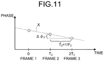
- FIG. 11 is a diagram illustrating a second photographing process according to the first embodiment of the present disclosure.
- the control unit 30 and the control unit 15 switch the operation modes of the light source 2 and the distance measuring device 3 from the operation modes for the first photographing process.
- the control unit 30 and the control unit 15 switch the operation modes such that the frame rates of the light source 2 and the distance measuring device 3 become a predetermined frame rate F 2 .
- the ToF sensor 23 captures the object 4 to acquire image data. Then, the phase calculation unit 24 calculates the phase ⁇ of the image data acquired for each frame.
- the estimation unit 28 calculates a deviation amount ⁇ 2 of the phase ⁇ between the adjacent frames, and then calculates a frequency deviation amount ⁇ f 2 from the deviation amount ⁇ 2 , using the following Expression (10).
- ⁇ f 2 ⁇ ⁇ 2 ⁇ F 2 / 2 ⁇
- the true deviation amount ⁇ f GT is obtained by obtaining the integer N 1 in the above Expression (9) and the integer N 2 in the Expression (11).
- the integer N 1 and the integer N 2 can be obtained by using a method known as the "Chinese remainder theorem”. Next, an example using this method will be described.
- a least common multiple A is a least common multiple of the frame rate F 1 in the first photographing process and the frame rate F 2 in the second photographing process. Then, the estimation unit 28 calculates a value A 1 and a value A 2 from the following Expressions (12) and (13), using the least common multiple A.
- a 1 A / F 1
- a 2 A / F 2
- the frame rates F 1 and F 2 are selected such that the least common multiple A does not coincide with the frame rates F 1 and F 2 .
- the estimation unit 28 calculates a value e from the following Expression (14), using the deviation amount ⁇ f 1 calculated by the above Expression (8) and the deviation amount ⁇ f 2 calculated by the Expression (10).
- e A ⁇ ⁇ f 1 ⁇ ⁇ f 2 / F 1 ⁇ F 2
- the estimation unit 28 calculates an integer N 2 ' as in the following Expressions (19) and (20). Note that, for calculation, the integer N 2 ' is used as the integer N 2 , and 0 ⁇ N 2 ' ⁇ A 2 is satisfied.
- the estimation unit 28 calculates the integer N 2 as in the following expressions (21) to (23).
- the estimation unit 28 can calculate the true deviation amount ⁇ f GT between the modulation frequency f L of the light source 2 and the modulation frequency f s of the distance measuring device 3 from the following Expression (24), using the integer N 2 calculated as described above.
- ⁇ f GT N 2 ⁇ F 2 + ⁇ f 2
- estimation unit 28 can verify whether or not the true deviation amount ⁇ f GT is correctly calculated by replacing various numerical values of the first photographing process and the second photographing process and applying the method described in the above Expressions (12) to (24) again.
- the adjustment unit 29 can adjust, using the above Expression (24), a new modulation frequency f s (N) of the distance measuring device 3 as in the following Expression (25) .
- f S N f S + ⁇ f GT
- the adjustment unit 29 can adjust the modulation frequency f s of the distance measuring device 3 to the modulation frequency f s (N) by adjusting the value of the PLL coefficient C s of the PLL circuit 22.
- an estimation range of the true deviation amount ⁇ f GT can be set to a range of -A/2 (Hz) ⁇ ⁇ f GT ⁇ A/2 (Hz) .
- the least common multiple A is 120, so that the estimation range of the true deviation amount ⁇ f GT can be set to a range of -60 (Hz) ⁇ ⁇ f GT ⁇ +60 (Hz).
- the estimation range of the deviation amount ⁇ f is in a range of -F/2 (Hz) ⁇ ⁇ f GT ⁇ F/2 (Hz).
- the estimation range of the deviation amount ⁇ f is in a range of -15 (Hz) ⁇ ⁇ f GT ⁇ +15 (Hz) .
- the estimation range of the true deviation amount ⁇ f GT can be expanded. Therefore, according to the first embodiment, even when the modulation frequency f L of the light source 2 and the modulation frequency f s of the distance measuring device 3 are greatly deviated, the modulation frequency f s of the distance measuring device 3 can be matched with the modulation frequency f L of the light source 2.
- the modulation frequency f L (i.e., the true deviation amount ⁇ f GT ) of the light source 2 is estimated based on the plurality of pieces of image data captured while the frame rate is switched between the frame rates F 1 and F 2 by the control unit 30.
- the modulation frequency f s of the ToF sensor 23 i.e., the distance measuring device 3
- the modulation frequency f L of the light source 2 can be matched with the modulation frequency f L of the light source 2.
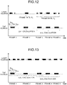
- FIG. 12 is a diagram illustrating an example of an operation in the estimation process of the distance measuring system 1 according to the first embodiment of the present disclosure.
- the control unit 30 and the control unit 15 switch both operation modes of the light source 2 and the ToF sensor 23 of the distance measuring device 3.
- control unit 30 and the control unit 15 perform the first photographing process. Specifically, as illustrated in FIG. 12 , the control unit 30 and the control unit 15 operate the light source 2 and the ToF sensor 23 to be synchronously turned on/off at the same frame rate F 1 (e.g., 30 (fps)) .
- F 1 e.g., 30 (fps)
- control unit 30 sets the operation mode of the distance measuring device 3 in accordance with the operation mode of the light source 2 communicated in advance by the communication unit 31. Furthermore, the control unit 30 and the control unit 15 can accurately synchronize the light source 2 and the ToF sensor 23 by using a precision time protocol (PTP) technology.
- PTP precision time protocol
- the ToF sensor 23 acquires data of the plurality of components Q 0 , Q 90 , Q 180 , and Q 270 for each frame. Then, the phase calculation unit 24 calculates the phase ⁇ for each frame based on the data of the plurality of components Q 0 , Q 90 , Q 180 , and Q 270 .
- the estimation unit 28 calculates the deviation amount ⁇ 1 of the phase ⁇ between the adjacent frames at the frame rate F 1 .
- control unit 30 and the control unit 15 perform the second photographing process. Specifically, the control unit 30 and the control unit 15 switch the operation mode such that the light source 2 and the ToF sensor 23 are synchronously turned on/off at the frame rate F 2 (e.g., 40 (fps)) different from the frame rate F 1 .
- F 2 e.g. 40 (fps)
- control unit 30 switches the operation mode of the distance measuring device 3 in accordance with the operation mode of the light source 2 communicated in advance by the communication unit 31.
- the ToF sensor 23 acquires data of the plurality of components Q 0 , Q 90 , Q 180 , and Q 270 for each frame. Then, the phase calculation unit 24 calculates the phase ⁇ for each frame based on the data of the plurality of components Q 0 , Q 90 , Q 180 , and Q 270 .
- the estimation unit 28 calculates difference (deviation amount) ⁇ 2 of the phase ⁇ between the adjacent frames at the frame rate F 2 . Note that, since the subsequent process is described above, description thereof is omitted.
- the light emission time of the light source 2 can be minimized. Therefore, according to the example in FIG. 12 , power consumption of the distance measuring system 1 can be reduced.
- FIG. 13 is a diagram illustrating another example of the operation in the estimation process of the distance measuring system 1 according to the first embodiment of the present disclosure.
- the control unit 30 switches only the operation mode of the ToF sensor 23 of the distance measuring device 3.
- control unit 30 performs the first photographing process. Specifically, as illustrated in FIG. 13 , the control unit 30 operates the ToF sensor 23 to be turned ON/OFF at the predetermined frame rate F 1 (for example, 30 (fps)). Note that, in the example in FIG. 13 , the light source 2 is controlled to continuously emit the emission light L1.
- F 1 for example, 30 (fps)
- the ToF sensor 23 acquires data of the plurality of components Q 0 , Q 90 , Q 180 , and Q 270 for each frame. Then, the phase calculation unit 24 calculates the phase ⁇ for each frame based on the data of the plurality of components Q 0 , Q 90 , Q 180 , and Q 270 .
- the estimation unit 28 calculates the deviation amount ⁇ 1 of the phase ⁇ between the adjacent frames at the frame rate F 1 .
- control unit 30 performs the second photographing process. Specifically, the control unit 30 switches the operation mode so as to turn ON/OFF the ToF sensor 23 at the frame rate F 2 (e.g., 40 (fps)) different from the frame rate F 1 .
- F 2 e.g. 40 (fps)
- the ToF sensor 23 acquires data of the plurality of components Q 0 , Q 90 , Q 180 , and Q 270 for each frame. Then, the phase calculation unit 24 calculates the phase ⁇ for each frame based on the data of the plurality of components Q 0 , Q 90 , Q 180 , and Q 270 .
- the estimation unit 28 calculates the deviation amount ⁇ 2 of the phase ⁇ between the adjacent frames at the frame rate F 2 . Note that, since the subsequent process is described above, description thereof is omitted.
- the modulation frequency f L of the light source 2 can be estimated even in a case where the communication unit 16 is not provided in the light source 2. Therefore, according to the example in FIG. 13 , since the communication unit 16 can be omitted from the light source 2, a cost of the distance measuring system 1 can be reduced.
- the first embodiment described above gives the example in which the modulation frequency f s of the distance measuring device 3 is adjusted in order to match the modulation frequency f s of the distance measuring device 3 with the modulation frequency f L of the light source 2.
- a target to be adjusted is not limited to the modulation frequency f s of the distance measuring device 3.
- the adjustment unit 29 may adjust the modulation frequency f L of the light source 2.
- the adjustment unit 29 may adjust both the modulation frequency f L of the light source 2 and the modulation frequency f s of the distance measuring device 3.
- the adjustment unit 29 may send to the control unit 15 a command for controlling the PLL coefficient C L of the PLL circuit 12 via the communication unit 31 and the communication unit 16.
- the first embodiment described so far gives the example of switching the frame rates F of the light source 2 and the distance measuring device 3.
- the operation mode to be switched is not limited to the frame rate F.
- an example of switching modulation frequencies f L and f s of the light source 2 and the distance measuring device 3 will be described with reference to FIG. 14 to FIG. 17 .
- FIG. 14 is a diagram illustrating a first photographing process according to the second embodiment of the present disclosure.
- the control unit 30 and the control unit 15 set operation modes, so that the modulation frequencies of the light source 2 and the distance measuring device 3 become predetermined modulation frequencies f L1 and f S1 .
- control unit 30 changes the PLL coefficient of the PLL circuit 22 to C S1 so as to match the PLL coefficient C L1 of the PLL circuit 12, thereby setting the operation mode so that the modulation frequency f S1 of the distance measuring device 3 matches the modulation frequency f L1 of the light source 2.
- the modulation frequencies f L1 and f S1 are frequencies considered to be equal to each other.
- the frame rate is constant at F.
- the ToF sensor 23 captures the object 4 to acquire image data. Then, the phase calculation unit 24 calculates the phase ⁇ of the acquired image data for each frame.
- the estimation unit 28 calculates the deviation amount ⁇ 1 of the phase ⁇ between the adjacent frames, and calculates the frequency deviation amount ⁇ f 1 from the deviation amount ⁇ 1 , using the following Expression (26).
- ⁇ f 1 ⁇ ⁇ 1 ⁇ F / 2 ⁇
- FIG. 15 is a diagram illustrating a second photographing process according to the second embodiment of the present disclosure. Subsequently, the control unit 30 and the control unit 15 switch the operation modes of the light source 2 and the distance measuring device 3 from the operation modes for the first photographing process.
- the control unit 30 switches the operation mode so that the modulation frequency f S2 of the distance measuring device 3 is matched with the modulation frequency f L2 of the light source 2.
- the control unit 30 changes the PLL coefficient C S2 of the PLL circuit 22 so that the PLL coefficient of the PLL circuit 12 matches with C L2 .
- the modulation frequencies f L2 and f S2 are frequencies considered to be equal to each other.
- the ToF sensor 23 captures the object 4 to acquire image data. Then, the phase calculation unit 24 calculates the phase ⁇ of the acquired image data for each frame.
- the estimation unit 28 calculates the deviation amount ⁇ 2 of the phase ⁇ between the adjacent frames, and then calculates a frequency deviation amount ⁇ f 2 from the deviation amount ⁇ 2 , using the following Expression (28).
- ⁇ f 2 ⁇ ⁇ 2 ⁇ F / 2 ⁇
- the error ⁇ f Err is obtained by obtaining the integer N 1 in the above Expression (27) and the integer N 2 in the Expression (29).
- the integer N 1 and the integer N 2 can be obtained by using a method known as the "Chinese remainder theorem". Next, an example using this method will be described.
- the PLL coefficient C S1 of the PLL circuit 12 in the first photographing process and the PLL coefficient C S2 of the PLL circuit 12 in the second photographing process set the value C S1 and the value C S2 such that C S1 ⁇ f CL1 and C S2 ⁇ f CL1 are not mutually dividable.
- C is set such that a value A 1 and a value A 2 of the following Expressions (30) and (31) are values that are prime to each other.
- a 1 C / C S 1
- a 2 C / C S 2
- the estimation unit 28 calculates the value e from the following Expression (32), using the deviation amount ⁇ f 1 calculated by the above Expression (26) and the deviation amount ⁇ f 2 calculated by the Expression (28).
- e C / C S 1 ⁇ C S 2 ⁇ F ⁇ C S 2 ⁇ ⁇ f 1 ⁇ C S 1 ⁇ ⁇ f 2
- the estimation unit 28 calculates an integer N 2 ' as in the following Expressions (37) and (38). Note that, for calculation, the integer N 2 ' is used as the integer N 2 , and 0 ⁇ N 2 ' ⁇ A 1 is satisfied.
- the estimation unit 28 calculates the integer N 2 as in the following Expressions (39) to (41).
- the estimation unit 28 can calculate the error ⁇ f Err between the frequency f CL1 of the clock signal generated by the light source clock 11 and the frequency f CL2 of the clock signal generated by the sensor clock 21 from the following Expression (42), using the integer N 2 calculated as described above.
- ⁇ f Err ⁇ f 2 + N 2 ⁇ F / C S2
- estimation unit 28 can verify whether or not the error ⁇ f Err is correctly calculated by replacing various numerical values of the first photographing process and the second photographing process and applying the method described in the above Expressions (26) to (42) again.
- the adjustment unit 29 can adjust a new modulation frequency f s (N) of the distance measuring device 3 based on the error ⁇ f Err calculated by the above Expression (42). As a result, it is possible to eliminate the deviation between the modulation frequency f L of the light source 2 and the modulation frequency f s (N) of the distance measuring device 3. Thus, the distance d can be accurately calculated.
- the adjustment unit 29 can adjust the modulation frequency f s of the distance measuring device 3 to the modulation frequency f s (N) by adjusting the PLL coefficient C s of the PLL circuit 22.
- the estimation range of the error ⁇ f Err can be expanded. Therefore, according to the second embodiment, even when the modulation frequency f L of the light source 2 and the modulation frequency f s of the distance measuring device 3 are greatly deviated, the modulation frequency f s of the distance measuring device 3 can be matched with the modulation frequency f L of the light source 2.
- the error ⁇ f Err of the sensor clock 21 of the distance measuring device 3 with respect to the light source clock 11 of the light source 2 is estimated based on the plurality of pieces of image data captured by switching the modulation frequencies f L and f s by the control unit 30 and the control unit 15.
- the modulation frequency f s of the ToF sensor 23 i.e., the distance measuring device 3
- the modulation frequency f L of the light source 2 can be matched with the modulation frequency f L of the light source 2.
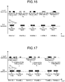
- FIG. 16 is a diagram illustrating an example of an operation in the estimation process of the distance measuring system 1 according to the second embodiment of the present disclosure.
- the control unit 30 and the control unit 15 alternately switch the modulation frequencies f L and f s of the light source 2 and the ToF sensor 23 for each frame.
- Control unit 30 and control unit 15 perform the first photographing process in the first frame (hereinafter also referred to as a frame 1). Specifically, as illustrated in FIG. 16 , the control unit 30 and the control unit 15 set the modulation frequency of the light source 2 to f L1 and set the modulation frequency of the distance measuring device 3 (i.e., the ToF sensor 23) to f S1 in the frame 1.
- the control unit 30 and the control unit 15 set the modulation frequency of the light source 2 to f L1 and set the modulation frequency of the distance measuring device 3 (i.e., the ToF sensor 23) to f S1 in the frame 1.
- control unit 30 sets the modulation frequency of the light source 2 to f L1 by sending a command to the control unit 15 via the communication unit 31 and the communication unit 16.
- the operation modes of the light source 2 and the distance measuring device 3 may be set with the setting of the light source 2 as a master, and the distance measuring device 3 as a slave.
- the modulation frequency f L1 may be set to the light source 2 and the modulation frequency f S1 may be set to the distance measuring device 3 by switching the operation modes of both the light source 2 and the distance measuring device 3 at predetermined time.
- the ToF sensor 23 acquires data of the plurality of components Q 0 , Q 90 , Q 180 , and Q 270 in the frame 1. Then, the phase calculation unit 24 calculates the phase ⁇ of the frame 1 based on the data of the plurality of components Q 0 , Q 90 , Q 180 , and Q 270 .
- control unit 30 and the control unit 15 perform the second photographing process in the next frame (hereinafter also referred to as a frame 2). Specifically, as illustrated in FIG. 16 , the control unit 30 and the control unit 15 set the modulation frequency of the light source 2 to f L2 and set the modulation frequency of the distance measuring device 3 (i.e., the ToF sensor 23) to f S2 in the frame 2.
- the distance measuring device 3 i.e., the ToF sensor 23
- the ToF sensor 23 acquires data of the plurality of components Q 0 , Q 90 , Q 180 , and Q 270 in the frame 2. Then, the phase calculation unit 24 calculates the phase ⁇ of the frame 2 based on the data of the plurality of components Q 0 , Q 90 , Q 180 , and Q 270 .
- the first photographing process is performed in frames 3, 5, 7, and so on
- the second photographing process is performed in frames 4, 6, 8, and so on.
- the estimation unit 28 calculates the deviation amount ⁇ 1 of the phase ⁇ at the modulation frequencies f L1 and f S1 from the phase ⁇ acquired in the first photographing process (frames 1, 3, 5, and so on). Furthermore, the estimation unit 28 calculates the deviation amount ⁇ 2 of the phase ⁇ at the modulation frequencies f L2 and f S2 from the phase ⁇ acquired in the second photographing process (frames 2, 4, 6, and so on). Note that, since the subsequent process is described above, description thereof is omitted.
- the above-described error ⁇ f Err can be calculated by alternately switching the modulation frequencies f L and f s of the light source 2 and the ToF sensor 23.
- FIG. 17 is a diagram illustrating another example of the operation in the estimation process of the distance measuring system 1 according to the second embodiment of the present disclosure.
- an interval between the frame (e.g., frame 1) in which the first photographing process is performed and the frame (e.g., frame 2) of the second photographing process performed subsequently to the first photographing process is made as short as possible.
- the value of the distance d of the object 4 in the first photographing process and the value of the distance d of the object 4 in the second photographing process to be subsequently performed can be brought close to each other. Therefore, according to the example in FIG. 17 , even when the object 4 slightly moves, the error ⁇ f Err can be calculated satisfactorily.
- the second embodiment described so far gives the example in which the light source 2 and the ToF sensor 23 are switched to two operation modes, but the number of operation modes to be switched to is not limited to two. The operation may be switched to three or more operation modes.
- the second embodiment described above gives the example in which the modulation frequency f s of the distance measuring device 3 is adjusted in order to match the modulation frequency f s of the distance measuring device 3 with the modulation frequency f L of the light source 2.
- a target to be adjusted is not limited to the modulation frequency f s of the distance measuring device 3.
- the adjustment unit 29 may adjust the modulation frequency f L of the light source 2.
- the adjustment unit 29 may adjust both the modulation frequency f L of the light source 2 and the modulation frequency f s of the distance measuring device 3.
- FIG. 18 is a diagram illustrating an example of an operation in the estimation process of the distance measuring system 1 according to the third embodiment of the present disclosure.
- the deviation amount ⁇ f between the modulation frequency f L and the modulation frequency f s is calculated using the method described in the above Expressions (1) to (6).
- the deviation amount ⁇ f calculated here has the "indefiniteness of 2 ⁇ ”
- a true value of the deviation amount ⁇ f is expressed by the following Expression (43).
- ⁇ f true value ⁇ f + F ⁇ N (N: Integer)
- the deviation amount ⁇ f having the highest adequacy is regarded as the true deviation amount ⁇ f (true value) in consideration of the indefiniteness of 2 ⁇ .
- the estimation unit 28 selects one value for the integer N.
- control unit 30 adjusts the modulation frequency f s of the distance measuring device 3 based on the deviation amount ⁇ f (true value) obtained by inputting the selected value for the integer N in the above Expression (43).
- the ToF sensor 23 acquires data of the plurality of components Q 0 , Q 90 , Q 180 , and Q 270 at the adjusted modulation frequencies f L and f s , as illustrated in FIG. 18 .
- the estimation unit 28 selects a value for a different integer N.
- the control unit 30 readjusts the modulation frequency f s of the distance measuring device 3 based on the deviation amount ⁇ f (true value) obtained by inputting the different value for the integer N in the above Expression (43).
- control unit 30 switches the operation mode of the distance measuring device 3 so that the modulation frequency f s is changed in increments of F (Hz) that is a value of the frame rate.
- the confidence value of the different integer N is calculated by a process similar to the above. Further, by the process similar to the above, confidence values in a case where the integer N is 0, ⁇ 1, ⁇ 2, and so on are calculated.
- the estimation unit 28 regards the integer N gaining the highest confidence value as the integer N with the highest adequacy. Then, the estimation unit 28 can calculate the true value of the deviation amount ⁇ f by inputting the integer N considered to have the highest adequacy in the above Expression (43).
- the deviation amount ⁇ f between the modulation frequency f L and the modulation frequency f s can be calculated by switching the operation modes of the distance measuring device 3 and calculating the confidence value in each operation mode.
- the modulation frequency f s of the ToF sensor 23 i.e., the distance measuring device 3
- the modulation frequency f s of the ToF sensor 23 can be matched with the modulation frequency f L of the light source 2.
- a search is performed by changing the modulation frequency of the ToF sensor 23, but the search may be performed by changing the modulation frequency of the light source 2.
- the control unit 15 changes the modulation frequency f L of the light source in increments of F (Hz) that is a value of the frame rate via the communication unit 31 and the communication unit 16.
- the modulation frequency f L of the light source 2 can be matched with the modulation frequency f s of the ToF sensor 23 (i.e., distance measuring device 3).
- the modulation frequencies f L and f S are changed in increments of F (Hz) that is the value of the frame rate. For example, when the frame rate is 30 (fps), the modulation frequency f L or f s is changed in increments of 30 (Hz). As a result, useless search can be prevented.
- the calculation formula of the confidence value used in the third embodiment is not limited to Expression (44).
- the following Expression (45) or Expression (46) is also applicable as a calculation formula of the confidence value.
- Confidence value Q 180 ⁇ Q 0 + Q 90 ⁇ Q 270
- Confidence value max Q 0 Q 90 Q 180 Q 270
- FIG. 19 is a flowchart illustrating a process procedure of the estimation process and the adjustment process according to the first embodiment.
- control unit 30 or the control unit 15 selects one frame rate (e.g., a frame rate F 1 ) from a plurality of frame rates set in advance as candidates of a plurality of operation modes (Step S101).
- one frame rate e.g., a frame rate F 1
- the ToF sensor 23 measures a phase image in a certain frame (Step S102).
- the ToF sensor 23 measures the components Q 0 , Q 90 , Q 180 , and Q 270 in the certain frame and calculates by using Expression (4).
- the ToF sensor 23 measures a phase image in another frame (Step S103). In other words, the ToF sensor 23 measures the components Q 0 , Q 90 , Q 180 , and Q 270 in another frame and calculates by using Expression (4).
- the moving subject detection unit 27 detects a moving subject position (i.e., a position of the moving subject) from the image captured by the ToF sensor 23 (Step S104).
- the estimation unit 28 calculates a deviation amount of the phase ⁇ at the selected one frame rate based on the phase images measured in Steps S102 and S103 (Step S105).
- Step S104 the position of the moving subject detected in Step S104 is excluded from the phase image used in Step S105. This is because it is assumed that the subject is stationary in a process of calculating the deviation amount of the phase ⁇ , and thus it is difficult to accurately calculate the deviation amount of the phase ⁇ when the position of the moving subject is included.
- Step S106 determines whether data for a prescribed number of frames has been acquired. Then, when the data has not been acquired for the prescribed number of frames (Step S106, No), the process returns to Step S102.
- the estimation unit 28 calculates an average deviation amount of all the acquired phases (Step S107), and regards the average value as the deviation amount of the phase ⁇ at the one selected frame rate.
- the estimation unit 28 determines whether or not the deviation amounts of the phases ⁇ at all candidate frame rates have been calculated (Step S108). Then, when the deviation amounts of the phases ⁇ at all candidate frame rates have not been calculated (Step S108, No), the control unit 30 or the control unit 15 selects another frame rate (e.g., frame rate F 2 ) (Step S109) and returns to the process in Step S102.
- another frame rate e.g., frame rate F 2
- the estimation unit 28 estimates the modulation frequency f L of the light source 2 based on the deviation amounts of the phases ⁇ at all candidate frame rates (Step S110).
- the adjustment unit 29 adjusts the modulation frequency f S of the distance measuring device 3 based on the modulation frequency f L of the light source 2 estimated in Step S110 (Step S111), and ends the process.
- FIG. 20 is a flowchart illustrating a process procedure of the estimation process and the adjustment process according to the second embodiment.
- control unit 30 or the control unit 15 selects one modulation frequency (e.g., modulation frequencies f L1 , or f S1 ) from a plurality of modulation frequencies set in advance as a plurality of candidate operation modes (Step S201) .
- modulation frequencies f L1 , or f S1 e.g., modulation frequencies f L1 , or f S1
- the ToF sensor 23 measures a phase image in a certain frame (Step S202).
- the ToF sensor 23 measures the components Q 0 , Q 90 , Q 180 , and Q 270 in the certain frame and calculates by using Expression (4).
- the ToF sensor 23 measures a phase image in another frame (Step S203). In other words, the ToF sensor 23 measures the components Q 0 , Q 90 , Q 180 , and Q 270 in another frame and calculates by using Expression (4).
- the moving subject detection unit 27 detects a moving subject position (i.e., the position of the moving subject) from the image captured by the ToF sensor 23 (Step S204) .
- the estimation unit 28 calculates the deviation amount of the phase ⁇ at the selected one modulation frequency based on the phase images measured in Steps S202 and S203 (Step S205). Note that the position of the moving subject detected in Step S204 is excluded from the phase image used in Step S205.
- Step S206 determines whether data for a prescribed number of frames has been acquired. Then, when the data for the prescribed number of frames has not been acquired (Step S206, No), the process returns to Step S202.
- the estimation unit 28 calculates an average value of all the acquired deviation amounts of phases (Step S207), and regards the average value as the deviation amount of the phase ⁇ in the one selected modulation frequency.
- the estimation unit 28 determines whether or not the deviation amount of the phase ⁇ has been calculated for all the candidate modulation frequencies (Step S208). Then, when the deviation amounts of the phases ⁇ for all the candidate modulation frequencies have not been calculated (Step S208, No), the control unit 30 or the control unit 15 selects another modulation frequency (e.g., modulation frequency f L2 or f S2 ) (Step S209), and returns to the process in Step S202.
- another modulation frequency e.g., modulation frequency f L2 or f S2
- the estimation unit 28 estimates the modulation frequency f L of the light source 2 based on the deviation amounts of the phases ⁇ for all the candidate modulation frequencies (Step S210).
- the adjustment unit 29 adjusts the modulation frequency f s of the distance measuring device 3 based on the modulation frequency f L of the light source 2 estimated in Step S210 (Step S211), and ends the process.
- FIG. 21 is a flowchart illustrating a process procedure of the estimation process and the adjustment process according to the third embodiment.
- the ToF sensor 23 measures a phase image in a certain frame (Step S301). In other words, the ToF sensor 23 measures the components Q 0 , Q 90 , Q 180 , and Q 270 in the certain frame and calculates by using Expression (4).
- the ToF sensor 23 measures a phase image in another frame (Step S302).
- the ToF sensor 23 measures the components Q 0 , Q 90 , Q 180 , and Q 270 in another frame and calculates by using Expression (4).
- the moving subject detection unit 27 detects a moving subject position (e.g., the position of the moving subject) from the image captured by the ToF sensor 23 (Step S303) .
- the estimation unit 28 calculates the deviation amount of the phase ⁇ based on the phase images measured in Steps S301 and S302 (Step S304). Note that the position of the moving subject detected in Step S303 is excluded from the phase images used in Step S304.
- the estimation unit 28 estimates the modulation frequency f L of the light source 2 based on the deviation amount of the phase ⁇ calculated in Step S304 (Step S305). Then, the control unit 30 selects one integer N from a plurality of integers set in advance as candidates (Step S306).
- control unit 30 adjusts modulation frequency f s based on the one integer N selected (Step S307). Then, the estimation unit 28 calculates a confidence value at the modulation frequency f s adjusted (Step S308).
- the estimation unit 28 determines whether confidence values for all candidate integers have been calculated (Step S309). Then, when the confidence values for all the candidate integers have not been calculated (Step S309, No), the control unit 30 selects another integer N (Step S310) and returns to the process in Step S307.
- the estimation unit 28 selects the integer N having the highest confidence value (Step S311).
- the estimation unit 28 estimates the modulation frequency f L of the light source 2 based on the selected integer N (Step S311).
- the adjustment unit 29 adjusts the modulation frequency f s of the distance measuring device 3 based on the modulation frequency f L of the light source 2 estimated in Step S311 (Step S312), and ends the process.
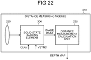
- FIG. 22 is a block diagram illustrating a configuration example of a distance measuring module 210 according to each embodiment of the present disclosure.
- the distance measuring module 210 includes an imaging lens 220, the solid-state imaging element 300, and a distance measurement calculation unit 230.
- the distance measuring module 210 is an example of the distance measuring device 3 (see FIG. 6 ) according to each embodiment.
- the solid-state imaging element 300 is an example of the ToF sensor 23 (see FIG. 6 ) according to each embodiment.
- the distance measurement calculation unit 230 is an example of the distance calculation unit 26 (see FIG. 6 ) according to each embodiment.
- the imaging lens 220 condenses the emission light L1 (see FIG. 6 ) from the plurality of light source units 14a, 14b, and so on (see FIG. 6 ) and the reflected light L2 (see FIG. 6 ) from the emission light L1, and guides condensed light to the solid-state imaging element 300.
- the solid-state imaging element 300 photoelectrically converts light from the imaging lens 220 to generate image data.
- a vertical synchronization signal VSYNC at a predetermined frequency and a reference clock CLKs are input to the solid-state imaging element 300.
- a frequency of the vertical synchronization signal VSYNC is set to a value (60 hertz or the like) lower than a frequency (20 megahertz or the like) of the emission light L1 emitted by the plurality of light source units 14a, 14b, and so on.
- a frequency of the reference clock CLKs is set to the same value as the frequency of the emission light L1.
- the reference clock CLKs is not synchronized with the emission light L1 of the plurality of light source units 14a, 14b, and so on, and a phase of the reference clock CLKs does not necessarily match with a phase of the emission light L1.
- the solid-state imaging element 300 generates the image data in synchronization with the vertical synchronization signal VSYNC or the like, and supplies the image data to the distance measurement calculation unit 230.
- the distance measurement calculation unit 230 creates a depth map including information on the distance d to the object 4 based on the image data supplied from the solid-state imaging element 300, and outputs the depth map to outside.
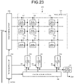
- FIG. 23 is a block diagram illustrating a configuration example of the solid-state imaging element 300 according to each embodiment of the present disclosure.
- the solid-state imaging element 300 includes a row scanning circuit 310, a pixel array unit 320, a timing control unit 340, a plurality of analog to digital (AD) conversion units 350, a column scanning circuit 360, and a signal processing unit 370.
- AD analog to digital
- a plurality of pixel circuits 330 is arranged in a two-dimensional lattice pattern.
- a set of pixel circuits 330 arranged in a predetermined direction is referred to as a "row”
- a set of pixel circuits 330 arranged in a direction perpendicular to the row is referred to as a "column”.
- the AD conversion unit 350 described above is provided for each column.
- the timing control unit 340 controls the row scanning circuit 310, the AD conversion unit 350, and the column scanning circuit 360 in synchronization with the vertical synchronization signal VSYNC.
- the row scanning circuit 310 sequentially selects rows and outputs pixel signals.
- the pixel circuit 330 outputs a pixel signal at a level corresponding to the received light quantity according to control by the row scanning circuit 310.
- the AD conversion unit 350 performs AD conversion of the pixel signals from corresponding columns.
- the AD conversion unit 350 outputs an AD-converted pixel signal to the signal processing unit 370 as pixel data according to control by the column scanning circuit 360.
- the column scanning circuit 360 sequentially selects the AD conversion units 350 and outputs the pixel data.
- the signal processing unit 370 performs signal processing such as a correlated double sampling (CDS) process on the image data including the pixel data.
- the signal processing unit 370 supplies the image data after the signal processing to the distance measurement calculation unit 230.
- CDS correlated double sampling
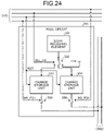
- FIG. 24 is a block diagram illustrating a configuration example of the pixel circuit 330 according to each embodiment of the present disclosure.
- the pixel circuit 330 includes a light receiving element 331, a transfer switch 332, charge storage units 333 and 334, and selection switches 335 and 336.
- the light receiving element 331 photoelectrically converts light to generate a charge.
- a single photon avalanche diode (SPAD) element, a photodiode, or the like is used as the light receiving element 331.
- the transfer switch 332 connects the light receiving element 331 to any one of the charge storage unit 333, the charge storage unit 334, and the reset power supply Vrst according to the control by the row scanning circuit 310.
- a "frequency on the ToF sensor 23 side" described in each embodiment is a cycle in which charges are distributed to the two charge storage units 333 and 334.
- the transfer switch 332 is realized by, for example, a plurality of metal-oxide-semiconductor (MOS) transistors. When connected to the reset power supply Vrst, the charge output from the drain of the MOS transistor is discarded, and the charge of the light receiving element 331 is initialized.
- MOS metal-oxide-semiconductor
- the charge storage units 333 and 334 store charges and generate a voltage corresponding to the stored charge amount.
- a floating diffusion layer is used as the charge storage units 333 and 334.
- the selection switch 335 opens and closes a line between the charge storage unit 333 and the AD conversion unit 350 according to the control by the row scanning circuit 310.
- the selection switch 336 opens and closes a line between the charge storage unit 334 and the AD conversion unit 350 according to the control by the row scanning circuit 310.
- the selection switch 335 transits into a closed state when the row scanning circuit 310 supplies a FD read signal RD_FD1
- the selection switch 336 transits into a closed state when the row scanning circuit 310 supplies the FD read signal RD_FD2.
- Each of these selection switches 335 and 336 is realized by, for example, a MOS transistor or the like.
- FIG. 25 is a timing chart illustrating an example of operation of the solid-state imaging element during a Q1Q2 detection period according to each embodiment of the present disclosure.
- the pixel circuit 330 alternately and repeatedly detects received light quantities Q1 and Q2 and received light quantities Q3 and Q4.
- a detection period of the received light quantities Q1 and Q2 is referred to as a "Q1Q2 detection period”
- a detection period of the received light quantities Q3 and Q4 is referred to as a "Q3Q4 detection period”.
- a period including the Q1Q2 detection period and the Q3Q4 detection period is referred to as a "measurement period”.
- a length of each of the Q1Q2 detection period and the Q3Q4 detection period is a cycle (e.g., 1/60 seconds) of the vertical synchronization signal VSYNC.
- the received light quantity Q1 is accumulation of received light quantities q1 from 0 degrees to 180 degrees over the Q1Q2 detection period with a specific phase (e.g., rise) of the reference clock CLKs as 0 degrees. Since the frequency of the reference clock CLKs is as high as 20 megahertz (MHz), the received light quantity q1 per cycle (1/20 microseconds) is very small, and it is difficult to detect the received light quantity q1.
- a specific phase e.g., rise
- the pixel circuit 330 accumulates each q1 over the Q1Q2 detection period such as 1/60 seconds longer than the cycle (1/20 microseconds) of the reference clock CLKs, and detects the total as the received light quantity Q1.
- the received light quantity Q2 is accumulation of received light quantities q2 from 180 degrees to 360 degrees over the Q1Q2 detection period.
- the received light quantity Q3 is accumulation of received light quantities q3 from 90 degrees to 270 degrees over the Q3Q4 detection period.
- the received light quantity Q4 is accumulation of received light quantities q4 from 270 degrees to 90 degrees over the Q3Q4 detection period.
- the distance measurement calculation unit 230 can calculate a phase difference dP between the reference clock CLKs and the received light.
- dP Arctan Q3 ⁇ Q4 / Q1 ⁇ Q2
- the row scanning circuit 310 supplies the reset signal RST to all the rows over a predetermined pulse period from the timing T1.
- the reset signal RST initializes charge accumulation amounts in the charge storage units 333 and 334 of all rows.
- the row scanning circuit 310 initializes charges in the light receiving elements 331 in all rows by a FD selection signal SEL_FD.
- the row scanning circuit 310 causes transfer of the charges generated by the light receiving element 331 to the charge storage unit 333 by the FD selection signal SEL_FD for all the rows from 0 degrees to 180 degrees in the cycle of the reference clock CLKs.
- the received light quantity q1 is accumulated in the charge storage unit 333.
- the row scanning circuit 310 causes transfer of the charge generated by the light receiving element 331 to the charge storage unit 334 by the FD selection signal SEL_FD for all rows from 180 degrees to 360 degrees in the cycle of the reference clock CLKs.
- the received light quantity q2 is accumulated in the charge storage unit 334.
- the row scanning circuit 310 sequentially supplies the FD read signals RD_FD1 and RD_FD2 to the first row.
- the pixel signals corresponding to the received light quantities Q1 and Q2 of the first row are read.
- the row scanning circuit 310 sequentially supplies the FD read signals RD_FD1 and RD_FD2 to the second row and reads the pixel signals. Thereafter, similarly, the row scanning circuit 310 sequentially selects a row and reads the pixel signal.
- each of the pixel circuits 330 detects the received light quantity Q1 from 0 degrees to 180 degrees and the received light quantity Q2 from 180 degrees to 360 degrees.
- the distance measuring device 3 includes the ToF sensor 23, the distance calculation unit 26, the mode switching unit (control unit 30), and the estimation unit 28.
- the ToF sensor 23 has a device-specific clock that is the sensor clock 21 for controlling the photographing timing and is different from the light source clock 11 for controlling the light-emitting timing of the light source 2.
- the ToF sensor 23 reflects the emission light L1 of the light source 2 emitting the pulse light on the surface of the object 4 to perform photographing.
- the distance calculation unit 26 calculates the distance d to the object 4 based on the image data captured by the ToF sensor 23.
- the mode switching unit (control unit 30) switches the operation mode of the ToF sensor 23.
- the estimation unit 28 estimates the modulation frequency f L of the light source 2 generated from the light source clock 11 based on a plurality pieces of image data captured by switching the operation mode by the mode switching unit (control unit 30).
- the modulation frequency f s of the ToF sensor 23 can be matched with the modulation frequency f L of the light source 2.
- the distance measuring device 3 further includes the adjustment unit 29 that adjusts the modulation frequency f s of the distance measuring device 3 generated from the sensor clock 21 based on the modulation frequency f L of the light source 2 estimated by the estimation unit 28.
- the modulation frequency f s of the ToF sensor 23 can be matched with the modulation frequency f L of the light source 2.
- the mode switching unit (control unit 30) switches the frame rate of the ToF sensor 23 to a plurality of different frame rates. Furthermore, the estimation unit 28 estimates the modulation frequency f L of the light source 2 based on phase information of the plurality of pieces of image data captured at the plurality of different frame rates.
- the modulation frequency f s of the distance measuring device 3 can be matched with the modulation frequency f L of the light source 2.
- the mode switching unit (control unit 30) switches the modulation frequency f L of the light source 2 and the modulation frequency f s of the distance measuring device 3 to a plurality of different frequencies.
- the estimation unit 28 estimates the modulation frequency f L of the light source 2 based on the phase information of the plurality of pieces of image data captured at the plurality of different modulation frequencies.
- the modulation frequency f s of the distance measuring device 3 can be matched with the modulation frequency f L of the light source 2.
- the mode switching unit changes the modulation frequency f L of the light source 2 or the modulation frequency f s of the distance measuring device 3 in increments of a predetermined frame rate.
- the distance measuring system 1 includes the light source clock 11 for controlling the modulation frequency of the light emission pulse, the light source 2 that emits the pulse light, and the distance measuring device 3 that measures the distance d to the object 4 using the emission light L1 of the light source 2.
- the distance measuring device 3 includes the ToF sensor 23, the distance calculation unit 26, the mode switching unit (control unit 30), and the estimation unit 28.
- the ToF sensor 23 has a device-specific clock that is the sensor clock 21 for controlling the photographing timing and is different from the light source clock 11.
- the ToF sensor 23 performs photographing by reflecting the emission light L1 of the light source 2 on the surface of the object 4.
- the distance calculation unit 26 calculates the distance d to the object 4 based on the image data captured by the ToF sensor 23.
- the mode switching unit (control unit 30) switches the operation modes of the light source 2 and the ToF sensor 23.
- the estimation unit 28 estimates the modulation frequency f L of the light source 2 generated from the light source clock 11 based on a plurality pieces of image data captured by switching the operation mode by the mode switching unit (control unit 30).
- the modulation frequency f s of the ToF sensor 23 can be matched with the modulation frequency f L of the light source 2.
- the distance measuring device 3 further includes the adjustment unit 29.
- the adjustment unit 29 adjusts at least one of the modulation frequency f L of the light source 2 and the modulation frequency f s of the distance measuring device 3 generated from the sensor clock 21 based on the modulation frequency f L of the light source 2 estimated by the estimation unit 28.
- the modulation frequency f s of the ToF sensor 23 can be matched with the modulation frequency f L of the light source 2.
- the mode switching unit switches the frame rate of the ToF sensor 23 to the plurality of different frame rates. Furthermore, the estimation unit 28 estimates the modulation frequency f L of the light source 2 based on phase information of the plurality of pieces of image data captured at the plurality of different frame rates.
- the modulation frequency f s of the distance measuring device 3 can be matched with the modulation frequency f L of the light source 2.
- the mode switching unit (control unit 30) switches the modulation frequency f L of the light source 2 and the modulation frequency f s of the distance measuring device 3 to the plurality of different frequencies.
- the estimation unit 28 estimates the modulation frequency f L of the light source 2 based on the phase information of the plurality of pieces of image data captured at the plurality of different modulation frequencies.
- the modulation frequency f s of the distance measuring device 3 can be matched with the modulation frequency f L of the light source 2.
- the mode switching unit (control unit 30) switches the modulation frequency f L of the light source 2 and the modulation frequency f L of the distance measuring device 3 to the plurality of different frequencies.
- the estimation unit 28 estimates the modulation frequency f L of the light source 2 based on the phase information of the image data captured at one modulation frequency and confidence values of the plurality of pieces of image data captured at the plurality of different modulation frequencies.
- the modulation frequency f s of the ToF sensor 23 can be matched with the modulation frequency f L of the light source 2.
- the mode switching unit changes the modulation frequency f L of the light source 2 or the modulation frequency f S of the distance measuring device 3 in increments of the predetermined frame rate.
- the light source 2 includes the communication unit 16 that receives, from the distance measuring device 3, information on the operation mode of the light source 2 set by the mode switching unit (control unit 30).
- the information on the operation mode of the light source 2 can be received from the distance measuring device 3.
- the distance measuring device 3 includes the communication unit 31 that receives, from the light source 2, information on the operation mode of the light source 2.
- the mode switching unit (control unit 30) sets the operation mode of the distance measuring device 3 based on the operation mode of the light source 2 received by the communication unit 31.
- the information on the operation mode of the light source 2 can be received from the light source 2.
- the method of adjusting the distance measuring device 3 includes the first photographing step, the mode switching step, the second photographing step, and the estimation step.
- the first photographing step uses the ToF sensor 23 having a device-specific clock that is the sensor clock 21 for controlling the photographing timing and is different from the light source clock 11 for controlling the modulation frequency of the light emission pulse of the light source 2.
- the ToF sensor 23 performs photographing by reflecting the emission light L1 of the light source 2 emitting the pulse light on the surface of the object 4.
- the mode switching step the operation mode of the ToF sensor 23 is switched.
- the ToF sensor 23 whose operation mode has been switched captures the object 4.
- the modulation frequency f L of the light source 2 generated from the light source clock 11 is estimated based on the plurality of pieces of image data captured in the first photographing step and the second photographing step.
- the modulation frequency f s of the ToF sensor 23 can be matched with the modulation frequency f L of the light source 2.
- the present technology can also have the following configurations.
Landscapes
- Engineering & Computer Science (AREA)
- Physics & Mathematics (AREA)
- Radar, Positioning & Navigation (AREA)
- Remote Sensing (AREA)
- Computer Networks & Wireless Communication (AREA)
- General Physics & Mathematics (AREA)
- Electromagnetism (AREA)
- Optical Radar Systems And Details Thereof (AREA)
- Measurement Of Optical Distance (AREA)
Applications Claiming Priority (2)
| Application Number | Priority Date | Filing Date | Title |
|---|---|---|---|
| JP2019138251A JP2021021633A (ja) | 2019-07-26 | 2019-07-26 | 測距装置、測距システムおよび測距装置の調整方法 |
| PCT/JP2020/023140 WO2021019929A1 (ja) | 2019-07-26 | 2020-06-12 | 測距装置、測距システムおよび測距装置の調整方法 |
Publications (2)
| Publication Number | Publication Date |
|---|---|
| EP4006586A1 true EP4006586A1 (de) | 2022-06-01 |
| EP4006586A4 EP4006586A4 (de) | 2022-09-07 |
Family
ID=74230603
Family Applications (1)
| Application Number | Title | Priority Date | Filing Date |
|---|---|---|---|
| EP20848464.2A Pending EP4006586A4 (de) | 2019-07-26 | 2020-06-12 | Abstandsmessvorrichtung, abstandsmesssystem und einstellverfahren für eine abstandsmessvorrichtung |
Country Status (4)
| Country | Link |
|---|---|
| US (1) | US20220260690A1 (de) |
| EP (1) | EP4006586A4 (de) |
| JP (1) | JP2021021633A (de) |
| WO (1) | WO2021019929A1 (de) |
Families Citing this family (2)
| Publication number | Priority date | Publication date | Assignee | Title |
|---|---|---|---|---|
| JPWO2022210330A1 (de) * | 2021-03-31 | 2022-10-06 | ||
| WO2024167310A1 (ko) * | 2023-02-07 | 2024-08-15 | 삼성전자 주식회사 | Tof 센서의 소모 전류를 감소하는 방법 및 이를 지원하는 전자 장치 |
Family Cites Families (10)
| Publication number | Priority date | Publication date | Assignee | Title |
|---|---|---|---|---|
| JP5019117B2 (ja) * | 2007-11-14 | 2012-09-05 | スタンレー電気株式会社 | 距離画像生成装置 |
| AU2011265572A1 (en) * | 2011-12-23 | 2013-07-11 | Canon Kabushiki Kaisha | Structured light system for robust geometry acquisition |
| KR101975971B1 (ko) * | 2012-03-19 | 2019-05-08 | 삼성전자주식회사 | 깊이 카메라, 다중 깊이 카메라 시스템, 그리고 그것의 동기 방법 |
| JP6328965B2 (ja) * | 2014-03-12 | 2018-05-23 | スタンレー電気株式会社 | 距離画像生成装置および距離画像生成方法 |
| US9170095B1 (en) * | 2014-04-08 | 2015-10-27 | Sony Corporation | Distance detection device and method including dynamically adjusted frame rate |
| IL235356A (en) * | 2014-10-27 | 2016-02-29 | Accubeat Ltd | A method and device for providing secure time synchronization from a satellite navigator system |
| JP2018031607A (ja) | 2016-08-23 | 2018-03-01 | ソニーセミコンダクタソリューションズ株式会社 | 測距装置、電子装置、および、測距装置の制御方法 |
| JP2018036144A (ja) * | 2016-08-31 | 2018-03-08 | キヤノン株式会社 | 距離計測システム、および距離計測方法 |
| DE102017105142B4 (de) * | 2017-03-10 | 2021-09-16 | Infineon Technologies Ag | Laufzeit-Bilderzeugungsvorrichtungen und ein Verfahren zum Anpassen einer Referenzfrequenz |
| JP2019106588A (ja) * | 2017-12-11 | 2019-06-27 | ソニーセミコンダクタソリューションズ株式会社 | 画像処理装置、画像処理方法及び撮像装置 |
-
2019
- 2019-07-26 JP JP2019138251A patent/JP2021021633A/ja active Pending
-
2020
- 2020-06-12 EP EP20848464.2A patent/EP4006586A4/de active Pending
- 2020-06-12 US US17/626,664 patent/US20220260690A1/en active Pending
- 2020-06-12 WO PCT/JP2020/023140 patent/WO2021019929A1/ja not_active Ceased
Also Published As
| Publication number | Publication date |
|---|---|
| EP4006586A4 (de) | 2022-09-07 |
| WO2021019929A1 (ja) | 2021-02-04 |
| JP2021021633A (ja) | 2021-02-18 |
| US20220260690A1 (en) | 2022-08-18 |
Similar Documents
| Publication | Publication Date | Title |
|---|---|---|
| US10382736B1 (en) | Two frequency time-of-flight three-dimensional image sensor and method of measuring object depth | |
| US11408983B2 (en) | Lidar 2D receiver array architecture | |
| US10509126B2 (en) | Method for driving a time-of-flight system | |
| CN109313264B (zh) | 基于飞行时间的测距方法和测距系统 | |
| EP3767323B1 (de) | Bistatisches radarsystem | |
| US7834985B2 (en) | Surface profile measurement | |
| US11664811B2 (en) | Mechanical shock detection and phase and frequency correction of a MEMS mirror | |
| US10048357B2 (en) | Time-of-flight (TOF) system calibration | |
| US11269065B2 (en) | Muilti-detector with interleaved photodetector arrays and analog readout circuits for lidar receiver | |
| EP2594959A1 (de) | System und Verfahren für Mehrfach-TOF-Kamerabetrieb mit Phasensprung | |
| JP5180501B2 (ja) | 測距装置及び測距方法 | |
| JP2006300616A (ja) | 空間情報検出システム | |
| EP4006586A1 (de) | Abstandsmessvorrichtung, abstandsmesssystem und einstellverfahren für eine abstandsmessvorrichtung | |
| JP7356454B2 (ja) | 測距撮像装置 | |
| JP4971744B2 (ja) | 強度変調光を用いた空間情報検出装置 | |
| CN111798503A (zh) | 利用飞行时间相机同时进行数据传输和深度图像记录 | |
| US11506787B2 (en) | Sensor device and measurement method | |
| US12130653B2 (en) | Delay time detection circuit, stamping information generation device, and delay time detection method | |
| JP2008241258A (ja) | 測距装置及び測距方法 | |
| US6961092B1 (en) | Three-dimensional image capturing device | |
| US11675079B2 (en) | Image sensing device and operating method thereof | |
| Steinbaeck et al. | A hybrid timestamping approach for multi-sensor perception systems | |
| Bijwaard et al. | Fundamentals of a scalable network in SPADnet-based PET systems | |
| KR20160088578A (ko) | 서로 다른 파장의 광신호를 이용한 거리 측정 방법 및 장치 | |
| WO2024046676A1 (en) | Direct time-of-flight sensor and corresponding measurement method |
Legal Events
| Date | Code | Title | Description |
|---|---|---|---|
| STAA | Information on the status of an ep patent application or granted ep patent |
Free format text: STATUS: THE INTERNATIONAL PUBLICATION HAS BEEN MADE |
|
| PUAI | Public reference made under article 153(3) epc to a published international application that has entered the european phase |
Free format text: ORIGINAL CODE: 0009012 |
|
| STAA | Information on the status of an ep patent application or granted ep patent |
Free format text: STATUS: REQUEST FOR EXAMINATION WAS MADE |
|
| 17P | Request for examination filed |
Effective date: 20211202 |
|
| AK | Designated contracting states |
Kind code of ref document: A1 Designated state(s): AL AT BE BG CH CY CZ DE DK EE ES FI FR GB GR HR HU IE IS IT LI LT LU LV MC MK MT NL NO PL PT RO RS SE SI SK SM TR |
|
| A4 | Supplementary search report drawn up and despatched |
Effective date: 20220805 |
|
| RIC1 | Information provided on ipc code assigned before grant |
Ipc: G01C 3/08 20060101ALI20220801BHEP Ipc: G01S 17/00 20200101ALI20220801BHEP Ipc: G01S 7/497 20060101ALI20220801BHEP Ipc: G01S 7/4915 20200101ALI20220801BHEP Ipc: G01S 7/4911 20200101ALI20220801BHEP Ipc: G01S 7/00 20060101ALI20220801BHEP Ipc: G01S 17/46 20060101ALI20220801BHEP Ipc: G01S 17/36 20060101ALI20220801BHEP Ipc: G01S 17/10 20200101AFI20220801BHEP |
|
| DAV | Request for validation of the european patent (deleted) | ||
| DAX | Request for extension of the european patent (deleted) | ||
| STAA | Information on the status of an ep patent application or granted ep patent |
Free format text: STATUS: EXAMINATION IS IN PROGRESS |
|
| 17Q | First examination report despatched |
Effective date: 20250225 |