EP4006601B1 - Microscope d'inspection de surface terminale à fibres optiques doté d'une tête optique remplaçable - Google Patents
Microscope d'inspection de surface terminale à fibres optiques doté d'une tête optique remplaçable Download PDFInfo
- Publication number
- EP4006601B1 EP4006601B1 EP21210420.2A EP21210420A EP4006601B1 EP 4006601 B1 EP4006601 B1 EP 4006601B1 EP 21210420 A EP21210420 A EP 21210420A EP 4006601 B1 EP4006601 B1 EP 4006601B1
- Authority
- EP
- European Patent Office
- Prior art keywords
- fiber
- optical
- optical head
- inspection microscope
- lens
- Prior art date
- Legal status (The legal status is an assumption and is not a legal conclusion. Google has not performed a legal analysis and makes no representation as to the accuracy of the status listed.)
- Active
Links
Images


Classifications
-
- G—PHYSICS
- G02—OPTICS
- G02B—OPTICAL ELEMENTS, SYSTEMS OR APPARATUS
- G02B6/00—Light guides; Structural details of arrangements comprising light guides and other optical elements, e.g. couplings
- G02B6/24—Coupling light guides
- G02B6/36—Mechanical coupling means
- G02B6/38—Mechanical coupling means having fibre to fibre mating means
- G02B6/3807—Dismountable connectors, i.e. comprising plugs
- G02B6/3833—Details of mounting fibres in ferrules; Assembly methods; Manufacture
- G02B6/385—Accessories for testing or observation of connectors
-
- G—PHYSICS
- G01—MEASURING; TESTING
- G01M—TESTING STATIC OR DYNAMIC BALANCE OF MACHINES OR STRUCTURES; TESTING OF STRUCTURES OR APPARATUS, NOT OTHERWISE PROVIDED FOR
- G01M11/00—Testing of optical apparatus; Testing structures by optical methods not otherwise provided for
- G01M11/30—Testing of optical devices, constituted by fibre optics or optical waveguides
- G01M11/31—Testing of optical devices, constituted by fibre optics or optical waveguides with a light emitter and a light receiver being disposed at the same side of a fibre or waveguide end-face, e.g. reflectometers
-
- G—PHYSICS
- G02—OPTICS
- G02B—OPTICAL ELEMENTS, SYSTEMS OR APPARATUS
- G02B21/00—Microscopes
- G02B21/02—Objectives
-
- G—PHYSICS
- G02—OPTICS
- G02B—OPTICAL ELEMENTS, SYSTEMS OR APPARATUS
- G02B6/00—Light guides; Structural details of arrangements comprising light guides and other optical elements, e.g. couplings
- G02B6/24—Coupling light guides
- G02B6/36—Mechanical coupling means
- G02B6/3616—Holders, macro size fixtures for mechanically holding or positioning fibres, e.g. on an optical bench
- G02B6/3624—Fibre head, e.g. fibre probe termination
-
- G—PHYSICS
- G06—COMPUTING OR CALCULATING; COUNTING
- G06T—IMAGE DATA PROCESSING OR GENERATION, IN GENERAL
- G06T7/00—Image analysis
- G06T7/0002—Inspection of images, e.g. flaw detection
- G06T7/0004—Industrial image inspection
-
- G—PHYSICS
- G06—COMPUTING OR CALCULATING; COUNTING
- G06V—IMAGE OR VIDEO RECOGNITION OR UNDERSTANDING
- G06V10/00—Arrangements for image or video recognition or understanding
- G06V10/10—Image acquisition
-
- G—PHYSICS
- G02—OPTICS
- G02B—OPTICAL ELEMENTS, SYSTEMS OR APPARATUS
- G02B6/00—Light guides; Structural details of arrangements comprising light guides and other optical elements, e.g. couplings
- G02B6/24—Coupling light guides
- G02B6/36—Mechanical coupling means
- G02B6/38—Mechanical coupling means having fibre to fibre mating means
- G02B6/3807—Dismountable connectors, i.e. comprising plugs
- G02B6/3873—Connectors using guide surfaces for aligning ferrule ends, e.g. tubes, sleeves, V-grooves, rods, pins, balls
- G02B6/3885—Multicore or multichannel optical connectors, i.e. one single ferrule containing more than one fibre, e.g. ribbon type
-
- G—PHYSICS
- G06—COMPUTING OR CALCULATING; COUNTING
- G06T—IMAGE DATA PROCESSING OR GENERATION, IN GENERAL
- G06T2207/00—Indexing scheme for image analysis or image enhancement
- G06T2207/10—Image acquisition modality
- G06T2207/10056—Microscopic image
-
- G—PHYSICS
- G06—COMPUTING OR CALCULATING; COUNTING
- G06T—IMAGE DATA PROCESSING OR GENERATION, IN GENERAL
- G06T2207/00—Indexing scheme for image analysis or image enhancement
- G06T2207/30—Subject of image; Context of image processing
- G06T2207/30108—Industrial image inspection
- G06T2207/30164—Workpiece; Machine component
Definitions
- the present description generally relates to inspection of optical-fiber connector endfaces, and more particularly to optical-fiber connector endface inspection microscopes adapted to inspect various types of optical-fiber connectors.
- optical-fiber inspection microscopes are commonly employed to visually inspect and/or to analyze the optical-fiber endface of an optical-fiber connector at installation or during maintenance of optical communication networks, in order to verify the quality of the optical-fiber connection.
- optical-fiber connector endface inspection microscopes are typically employed with interchangeable adapter tips so as to allow inspection of various types of optical-fiber connectors directly or as inserted in an optical-fiber connector adapter.
- Optical-fiber connector endface inspection microscopes are therefore typically designed for use with an adapter tip selected among a plurality of adapter tip types.
- Optical-fiber connectors now used in the industry can be split in two main categories, i.e., single-fiber connectors and multi-fiber connectors.
- optical-fiber connector endface inspection microscopes also need to support all these types of connectors.
- the inspection tip of the inspection microscope, as well as the objective lens must be small enough to avoid any physical interference with adjacent connectors (e.g., in a densely populated patch panel). Users may have to inspect a connector bulkhead while a fiber is connected in the adjacent bulkheads. Most of the time, to disconnect a fiber which may be "live", in order to allow the inspection of an unused connector bulkhead is simply impossible.
- the region of interest on the multi-fiber ferule is about 4.3 mm wide while the single-fiber is less than 1 mm.
- Adapter tips and lenses are optimized with these goals and constraints in mind, thereby creating two families of adapter tips, i.e., smaller single-fiber adapter tips and wider multi-fiber adapter tips.
- the traditional approach to conciliate adapter tips and lenses of two different sizes is to add an adaptor so as to either convert a multi-fiber inspection microscope into a single-fiber inspection microscope, or convert a single-fiber inspection microscope into a multi-fiber inspection microscope.
- some inspection microscopes are natively multi-fibers and are designed with a field-of-view allowing inspection of the whole endface of a multi-fiber connector.
- a single-fiber adaptor is added in place of a multi-fiber adapter tip to accept smaller single-fiber adapter tips. In this case, this is essentially a mechanical adaptor.
- One main drawback for this solution is to have a single-fiber image quality that is not on par with a dedicated single-fiber inspection microscope using the same adapter tip. More specifically, the single-fiber magnification level and optical path inherit the same compromises made to inspect multi-fiber connectors with 8 to 16 fiber per row.
- fiber inspection may be made particularly difficult when bulkheads are not well positioned for fiber inspection, e.g., because they are in a deep recess or because the presented angle is far from ideal.
- US 2019/391041 A1 describes an optical-fiber connector endface inspection microscope system comprising optical power measurement capability, wherein optical power measurement is provided via an optical power meter device implemented within an extension unit positioned along an optical path between the inspected optical-fiber connector endface and the optical-fiber connector endface inspection microscope.
- US 6,287,020 B1 relates to an observation apparatus for observing positions of optical fibers and a fusion splicer using the same for optical fibers.
- JP 2015 118036 A describes an imaging apparatus and imaging method for imaging a biological sample carried together with a liquid in a sample container.
- US 2014/327735 A1 describes a portable inspection probe using digital holography that is suitable for detecting defects and foreign particles on the mating surface of an optical fiber connector.
- an optical-fiber inspection microscope system that can be configured into either a single-fiber inspection microscope or a multi-fiber inspection microscope by using interchangeable optical heads (i.e., single-fiber head or multi-fiber head), including optical elements.
- Each head is designed specifically for one of the main families of connectors, e.g., single-fiber or multi-fiber.
- Each optical head brings an optical component usually part of the fiber inspection scope as an external element that is made interchangeable by swapping the optical head.
- Each optical head includes a head lens that is positioned in the optical head so as to be located close to the connector endface under inspection, allowing the use of inexpensive adapter tips without lenses in order to complete the adaptation to each connector "sub-type" (e.g., MPO APC, MPO UPC, Optitip, Q-ODC, etc.).
- These adapter tips are interchangeably connectable to their corresponding optical head.
- a user who wants to switch from one family of connectors to another can simply swap the optical head. Switching from one to another does not add any extra optical and mechanical components in the optical path and the image quality and size of the inspection microscope system can be optimal for either single-fiber or multi-fiber connector inspection. Switching heads instead of adding an adaptor may also provide the benefit of minimizing the mechanical tolerance stack-up of the system. Mechanical tolerances can become very critical when designing optical-fiber inspection microscope systems, especially when the system needs to adapt to various multifiber connectors or other particular connectors. Minimizing the mechanical tolerance stack-up can be key.
- This solution also brings any moving optical elements used for image focus inside the optical-fiber inspection microscope, and further away from the inspected connector endface.
- the first lens (head lens), which is the closest to the inspected connector endface is fixed, whereas the second lens is moveable for adjusting the focus.
- magnification level could then depend upon the focus (i.e., the position of the focusing lens).
- optical-fiber inspection microscopes are not only required to produce high-quality images on small elements, but they are also required to precisely measure defects on inspected optical fiber connector endfaces. Having different magnification levels can be problematic for such applications.
- This drawback may be overcome by providing a telecentric objective comprising a telecentric aperture stop.
- Another issue related to the focus being done by the second group of lenses is the higher level of mechanical tolerance and more importantly the level of positioning precision being required. This issue may be solved herein by arranging the optical components in a way which allows a longer travel for the focusing lenses to achieve a similar focus range on the object.
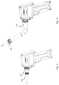
- an optical-fiber inspection microscope system 100 for inspecting an endface of an optical-fiber connector and which can be configured into either a single-fiber inspection microscope or a multi-fiber inspection microscope.
- the system 100 comprises a main housing structure 10 and mutually interchangeable optical heads, such as a multi-fiber head 12 and a single-fiber head 14.
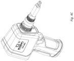
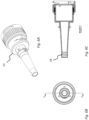
- Fig. 5 shows the multi-fiber optical head 12 in more details
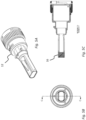
- Fig. 6 shows the single-fiber optical head 14 in more details.
- Each optical head 12, 14 is designed specifically for one of the main families of connectors, e.g., single-fiber or multi-fiber.
- Each optical head 12, 14 includes a relay lens 16, 18, that is positioned in the optical head so as to be located close to the connector endface under inspection, i.e., near the inspection end of the optical-fiber inspection microscope system 100.
- Each optical head 12, 14 brings an optical component usually part of the fiber inspection scope (i.e., the relay lens 16, 18) as an external element that is made interchangeable by swapping optical heads 12, 14. This interchangeability allow to configure the inspection microscope system 100 into either a single-fiber or a multi-fiber inspection microscope.
- the region of interest on a multi-fiber ferule is about 4.3 mm wide while the single-fiber is less than 1 mm.
- the multi-fiber relay lens 16 and the single-fiber relay lens 18 may therefore be optimally made with mutually different dimensions. They may be dimensioned so as to each capture the whole surface of the optical-fiber connector under inspection, while keeping the optical head and adapter tip no bigger than necessary so as to not mechanically interfere with adjacent connectors.
- the multi-fiber relay lens 16 may therefore be made wider than the single-fiber relay lens 18.
- This configuration also allows the use of inexpensive adapter tips, such as tips 20 or 22, which do not include lenses in order to complete the adaptation to each connector "sub-type" (e.g., MPOAPC, MPO UPC, Optitip, Q-ODC, etc.).
- These adapter tips are interchangeably connectable to its corresponding optical head.
- Each interchangeable adapter tip is configured to interface with one or more specific optical-fiber connector to be inspected.
- the single-fiber optical head 14 is made releasably connectable to single-fiber adapter tips and the multi-fiber optical head 14 is made releasably connectable to multi-fiber adapter tips.
- switching heads 12, 14 Users who want to switch from one family of connectors to another can simply swap optical heads 12, 14. Switching from one to another does not add any extra optical and mechanical components in the optical path and the image quality and size of the inspection microscope system can be optimal for both single-fiber and multi-fiber connector inspection. As explained hereinabove, switching heads instead of adding an adaptor may also provide the benefit of minimizing the mechanical tolerance stack-up of the system.
- adapter tips (20, 22 or other non-illustrated tips) each comprise a substantially elongated hollow member 60 defining a channel 62 between a proximal end 64 and a remote end 66, wherein illumination light may propagate to and back from the inspected connector endface. It further comprises an optical connector interface 68 at its proximal end 64 to mechanically engage with the optical connector (not shown) during inspection, as well as a connection mechanism 52 for releasable connection to the optical head (12, 14, 24 or other non-illustrated optical head) and having complementary engaging features 70, 72 respectively located on the adapter tip and the optical head.
- optical heads (12, 14, 24 or other non-illustrated optical heads) each comprise a substantially elongated hollow member 80 defining a channel 82 between a proximal end 84 and a remote end 86, wherein illumination light may propagate to and back from the inspected connector endface. It further comprises a relay lens 16 or 18 at its proximal end 64 and a connection mechanism 50 for releasable connection to the main housing 10 and having complementary engaging features 90, 92 respectively located on the optical head and the main housing 10.
- At least part of the elongated member 80 of the optical head may interlock into the hollow member 60 of the adapter tip so that the relay lens 16 or 18 of the optical head is positioned within the adapter tip.
- This configuration allows the relay lens 16 or 18 be located close to the connector endface under inspection, i.e., near the inspection end of the optical-fiber inspection microscope system 100.
- Each interchangeable optical head (12, 14, 24 or other non-illustrated optical head) may be made easily releasably connectable to the main housing structure 10 using a connection mechanism 50 such as a screw-threaded mechanism or twist and lock mechanism for example.
- a connection mechanism 50 such as a screw-threaded mechanism or twist and lock mechanism for example.
- the adapter tip 20 or 22 may be made releasably connectable to the optical head 12 or 14 using a similar connection mechanism 52.
- the interchangeable optical head can also be used to change the orientation of the connector under inspection relative to the optical-fiber inspection microscope in order to allow to reach optical-fiber connector bulkheads that are disposed at an angle within the patch panel.
- switching heads instead of adding an adaptor may advantageously allow a more ergonomic design.
- an angled adapter would need to be inserted between the optical-fiber connector bulkhead to be inspected and the optical-fiber inspection microscope.
- the overall inspection system would be longer and less ergonomic.
- the optical-fiber inspection microscope system 100 further comprises and angled optical head 24 that is interchangeable with one or more linear optical head such as the multi-fiber head 12 or the single-fiber head 14.
- Fig. 7 shows the angled optical head 24 in more details.
- the angled optical head 24 can be made either multi-fiber or single-fiber.
- the angled optical head 24 also includes a relay lens 26, that is positioned in the optical head so as to be located close to the connector endface under inspection.
- the angled optical head 24 further comprises a mirror 30 used to deviate an optical path between the inspected connector endface and the main housing structure 10 and so allow to create an angle in the optical head 24.
- additional lenses 28 may also be needed in the angled optical head 24 in order to relay the illumination light to and back from the inspected endface and extend the optical path of the angled optical head 24 compared to the single-fiber optical head 14 and the multi-fiber optical head 12.
- the multi-fiber angled head 24 may be manufactured so its proximal portion which inserts in and engage to adapter tips 20 is identical or has substantially the same shape as that of the multi-fiber head 12, so as to allow to interchangeably use the same adapter tips 20 for both heads 12, 24. The same can be applied to a single-fiber angled head and the single-fiber head 14.
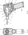
- FIG. 4 which comprises Fig. 4A and Fig. 4B , the optical-fiber connector endface inspection microscope system 100 of Fig. 1 is shown in more details.
- the inspection microscope system 100 is illustrated with optical head 12 but could likely have been illustrated with optical head 14.
- Fig. 4B illustrates one example embodiment of an optical-fiber connector endface inspection microscope system. It should be appreciated by those of ordinary skill in the art that various implementations of the inspection microscope can be envisaged as known in the art and that the embodiment illustrated herein is no way meant to be limitative.
- an optical-fiber connector endface inspection microscope system 100 incorporates an imaging assembly comprising an illumination source 30 for illuminating the connector endface to be inspected (not shown), an illumination beam splitter 32 to direct illumination light toward the connector endface, one or more image detector 34 (herein two image detectors) for capturing at least one image of the endface to be inspected, and imaging optics.
- the imaging optics comprises an objective lens system (and optionally other lenses, mirrors (see, e.g., 38) and/or other optical components (e.g., beamsplitter 48) defining objective optics), for imaging the illuminated connector endface, on the image plane(s) coinciding with the image detector(s) 34.
- the object plane as defined herein is determined by the objective lens system and coincides with the plane where the connector endface to be inspected (i.e., the object) should be positioned (within the focusing range of the objective lens system) to be suitably imaged on the image detector(s) 34.
- the optical path between the object plane and the image plane defines an imaging path of the inspection microscope, along which propagates the inspection light beam resulting from a reflection of illumination light on the connector endface, for optical magnification of the object (i.e., the connector endface) positioned on the object plane.
- the objective lens system comprises a focusing lens 36 for adjusting a focus of the objective lens system on the image detector(s) 34 and a fixed relay lens (here lens 16) disposed in the optical head (here 12), whereas the image detector(s) 34 and the focusing lens 36 are enclosed in the main housing structure 10.
- the objective lens system at least comprises the focusing lens 36 for adjusting a focus of the objective lens system on the image detector and a fixed relay lens 16 or 18.
- the focus is adjusted by moving the focusing lens using an actuator 46.
- the objective lens system may further comprise other lenses or optical elements as required by the optical design, which lenses and optical elements can be either fixed relative to the microscope system or movable, e.g., held fixed with the focusing lens.
- the objective lens system may further comprise lens 40 that is enclosed and held fixed within the main housing structure.
- magnification level could then depend upon the focus (i.e., the position of the focusing lens).
- optical-fiber inspection microscopes are not only required to produce high-quality images on small elements, but they are also required to precisely measure defects on inspected optical fiber connector endfaces. Having different magnification levels can be problematic for such applications.
- This drawback may be overcome by providing a telecentric objective comprising a telecentric aperture stop.
- the objective lens system is thereby configured to form a telecentric objective and comprises a telecentric aperture stop 42.
- a telecentric aperture stop is an aperture stop that is positioned at the focal point in an optical system, in order to reduce magnification variations caused by a slight displacement of the object plan.
- the aperture stop is positioned at or near the focal point of the objective lens system, i.e., at or near the focal point of the relay lens 16 or 18.
- the aperture stop 42 and the focusing lens 36 are together mounted in a lens holder 44.
- the distance between the two therefore remains fixed during focus. Focus is being adjusted by displacing the lens holder 44 using an actuator 46, thereby moving the focusing lens 36 and the aperture stop 42.
- the relay lens 16 or 18 and other optical elements of the objective lens system remain fixed within the inspection microscope system 100. Consequently, the distance between the aperture stop 42 and the relay lens 16 or 18 varies during focus adjustment but nevertheless remains close to the focal point of the relay lens 16 or 18 so as to obtain a substantially telecentric objective lens system.
- Another issue related to the focus being done by the second group of lenses is the higher level of mechanical tolerance and more importantly the level of positioning precision being required. This issue may be solved herein by arranging the optical components in a way which allows a longer travel for the focusing lenses to achieve a similar focus range on the object.
- focus may be adjusted using a deformable focusing lens instead of a movable focusing lens.
- both the focusing lens 36 and the relay lens 16 or 18 remain fixed during focus adjustment but the magnification may still depend upon the focus, i.e. the adjusted focal point of the deformable focusing lens.
- this drawback may be overcome with a telecentric objective comprising a telecentric aperture stop.
Landscapes
- Physics & Mathematics (AREA)
- General Physics & Mathematics (AREA)
- Engineering & Computer Science (AREA)
- Optics & Photonics (AREA)
- Chemical & Material Sciences (AREA)
- Analytical Chemistry (AREA)
- Theoretical Computer Science (AREA)
- Quality & Reliability (AREA)
- Computer Vision & Pattern Recognition (AREA)
- Multimedia (AREA)
- Microscoopes, Condenser (AREA)
Claims (10)
- Système de microscope d'inspection de surface terminale de connecteur à fibres optiques (100) destiné à l'inspection d'une surface terminale d'un connecteur à fibres optiques, le système de microscope d'inspection de surface terminale de connecteur à fibres optiques comprenant :un ou plusieurs détecteurs d'image (34) destinés à capturer au moins une image de la surface terminale à inspecter ;un système de lentilles d'objectif comprenant une lentille de focalisation (36) destinée au réglage d'une mise au point du système de lentilles d'obj ectif sur le détecteur d'image et une lentille relais fixe (16) ;une structure de boîtier principal (10) renfermant le détecteur d'image (34) et la lentille de focalisation (36) ; etune tête optique multifibre (12) et une tête optique monofibre (14), connectables de manière amovible et interchangeable à la structure de boîtier principale (10) ;ladite tête optique multifibre (12) et la tête optique monofibre (14) renfermant chacune une lentille relais qui forme la lentille relais fixe (16) du système de lentilles d'objectif lorsque l'une des têtes optiques est connectée au à la structure de boîtier principal ;ladite tête optique multifibre (12) pouvant être connectée de manière amovible à une pointe d'adaptateur multifibre (20) conçue pour s'interfacer avec des connecteurs à fibres optiques multifibre à inspecter et ladite tête optique monofibre (14) pouvant être connectée de manière amovible à une pointe d'adaptateur monofibre (22) conçue pour s'interfacer avec des connecteurs à fibres optiques monofibre à inspecter.
- Système de microscope d'inspection de surface terminale de connecteur à fibres optiques selon la revendication 1, comprenant en outre :au moins une pointe d'adaptateur multifibre (20) pouvant être connectée de manière amovible à la tête optique multifibre (12) et comprenant une interface de connecteur à fibres optiques multifibre (68) destinée à se mettre en prise mécaniquement avec un connecteur à fibres optiques multifibre à inspecter ; etau moins une pointe d'adaptateur monofibre (22) pouvant être connectée de manière amovible à la tête optique monofibre (14) et comprenant une interface de connecteur à fibres optiques monofibre (68) destinée à venir en prise mécaniquement avec un connecteur à fibres optiques monofibre à inspecter.
- Système de microscope d'inspection de surface terminale de connecteur à fibres optiques selon la revendication 1 ou 2, ladite lentille relais de la tête optique multifibre et ladite lentille relais de la tête optique monofibre possédant des dimensions mutuellement différentes.
- Système de microscope d'inspection de surface terminale de connecteur à fibres optiques selon l'une quelconque des revendications 1 à 3, ledit système de lentilles d'objectif étant conçu pour former un objectif télécentrique et comprenant un diaphragme télécentrique (42).
- Système de microscope d'inspection de surface terminale de connecteur à fibres optiques selon la revendication 4, ledit diaphragme étant positionné au niveau ou à proximité du foyer du système de lentilles d'objectif
- Système de microscope d'inspection de surface terminale de connecteur à fibres optiques selon la revendication 4 ou 5, ledit diaphragme et ladite lentille de focalisation étant montés ensemble dans un support de lentille et une distance entre le diaphragme et la lentille de focalisation restant fixe durant la mise au point.
- Système de microscope d'inspection de surface terminale de connecteur à fibres optiques selon la revendication 6, ladite mise au point étant réglée en déplaçant le support de lentille, déplaçant ainsi la lentille de focalisation et le diaphragme ; la lentille relais du système de lentilles d'objectif restant fixe à l'intérieur du système de microscope d'inspection durant le réglage de la mise au point.
- Système de microscope d'inspection de surface terminale de connecteur à fibres optiques selon la revendication 7, ledit système de lentilles d'objectif comprenant en outre une lentille fixe enfermée à l'intérieur de la structure de boîtier principal et durant le réglage de la mise au point, ladite lentille fixe restant fixe à l'intérieur du système de microscope d'inspection.
- Système de microscope d'inspection de surface terminale de connecteur à fibres optiques selon l'une quelconque des revendications 1 à 8, ladite tête optique multifibre (12) étant linéaire et ledit système comprenant en outre une tête optique inclinée (24), pouvant être connectée de manière amovible et interchangeable à la structure de boîtier principale (10).
- Système de microscope d'inspection de surface terminale de connecteur à fibres optiques selon la revendication 2, ladite pointe d'adaptateur multifibre (20) et ladite pointe d'adaptateur monofibre (22) comportant chacune un élément creux sensiblement allongé et ladite tête optique multifibre (12) et ladite tête optique monofibre (14) étant chacune conçues afin que, lorsqu'elles sont interconnectées avec leur pointe d'adaptateur respective, au moins une partie de la tête optique s'enclenche dans l'élément creux de la pointe d'adaptateur afin que la lentille relais de la tête optique soit positionnée à l'intérieur de la pointe d'adaptateur.
Applications Claiming Priority (3)
| Application Number | Priority Date | Filing Date | Title |
|---|---|---|---|
| US202063118789P | 2020-11-27 | 2020-11-27 | |
| US202163175980P | 2021-04-16 | 2021-04-16 | |
| US202163203758P | 2021-07-30 | 2021-07-30 |
Publications (2)
| Publication Number | Publication Date |
|---|---|
| EP4006601A1 EP4006601A1 (fr) | 2022-06-01 |
| EP4006601B1 true EP4006601B1 (fr) | 2024-07-31 |
Family
ID=78789819
Family Applications (1)
| Application Number | Title | Priority Date | Filing Date |
|---|---|---|---|
| EP21210420.2A Active EP4006601B1 (fr) | 2020-11-27 | 2021-11-25 | Microscope d'inspection de surface terminale à fibres optiques doté d'une tête optique remplaçable |
Country Status (2)
| Country | Link |
|---|---|
| US (1) | US12050149B2 (fr) |
| EP (1) | EP4006601B1 (fr) |
Families Citing this family (3)
| Publication number | Priority date | Publication date | Assignee | Title |
|---|---|---|---|---|
| US11086080B2 (en) * | 2019-05-29 | 2021-08-10 | Viavi Solutions Inc. | Alignment guide for inspecting a fiber optic end face |
| US12135458B2 (en) * | 2020-09-21 | 2024-11-05 | Panduit Corp. | Arrayed visual inspectors for fiber connectors and adapters |
| US20230288642A1 (en) * | 2022-03-14 | 2023-09-14 | Panduit Corp. | MPO Adapter for APC Connector Inspection |
Family Cites Families (8)
| Publication number | Priority date | Publication date | Assignee | Title |
|---|---|---|---|---|
| JP2920670B2 (ja) * | 1989-10-13 | 1999-07-19 | オリンパス光学工業株式会社 | 内視鏡対物レンズ |
| JP3176574B2 (ja) | 1997-10-15 | 2001-06-18 | 住友電気工業株式会社 | 光ファイバ観察装置および光ファイバ融着接続装置 |
| WO2013097041A1 (fr) | 2011-12-28 | 2013-07-04 | Exfo Inc. | Sonde holographique numérique portative pour l'inspection de connecteurs de fibres optiques et système et procédé d'inspection associés |
| JP6195373B2 (ja) | 2013-12-19 | 2017-09-13 | 株式会社Screenホールディングス | 撮像装置および撮像方法 |
| EP3096124B1 (fr) * | 2015-05-21 | 2018-09-05 | EXFO Inc. | Pointe d'adaptateur et système de microscope pour l'inspection de la surface terminale d'un connecteur à fibres optiques |
| US10175142B2 (en) | 2015-07-02 | 2019-01-08 | Exfo Inc. | Multiple-fiber connector inspection |
| US10900866B2 (en) | 2018-06-22 | 2021-01-26 | Exfo Inc. | Optical fiber endface inspection with optical power measurement |
| US10649154B1 (en) * | 2019-02-20 | 2020-05-12 | Lightel Technologies, Inc. | Field of view converter for fiber-optic connector endface inspector |
-
2021
- 2021-11-17 US US17/455,229 patent/US12050149B2/en active Active
- 2021-11-25 EP EP21210420.2A patent/EP4006601B1/fr active Active
Also Published As
| Publication number | Publication date |
|---|---|
| US20220170816A1 (en) | 2022-06-02 |
| EP4006601A1 (fr) | 2022-06-01 |
| US12050149B2 (en) | 2024-07-30 |
Similar Documents
| Publication | Publication Date | Title |
|---|---|---|
| EP3096124B1 (fr) | Pointe d'adaptateur et système de microscope pour l'inspection de la surface terminale d'un connecteur à fibres optiques | |
| US9841579B2 (en) | Multiple-fiber connector inspection | |
| US9915790B2 (en) | Fiber inspection microscope and power measurement system, fiber inspection tip and method using same | |
| EP4006601B1 (fr) | Microscope d'inspection de surface terminale à fibres optiques doté d'une tête optique remplaçable | |
| EP3945352B1 (fr) | Embout d'adaptateur et système de microscope associé pour l'inspection de la surface terminale d'un connecteur à fibres optiques | |
| US10088638B2 (en) | Optical fiber connection mechanism and optical fiber connection method | |
| US9733616B2 (en) | Portable digital holographic probe for the inspection of optical fiber connectors, and inspection system and method for the same | |
| US20170035275A1 (en) | Connection adapter for optical fiber and endoscope device | |
| EP4276504B1 (fr) | Pointe d'adaptateur et système de microscope pour inspecter des faces d'extrémité de connecteur à fibre optique duplex | |
| US10900866B2 (en) | Optical fiber endface inspection with optical power measurement | |
| US11274991B2 (en) | Fiber optic ferrule inspection tool | |
| CN220473740U (zh) | 一种光纤适配器 | |
| US20240255713A1 (en) | Adapter tip and microscope system for inspecting apc trans-duplex fiber-optic connectors | |
| US20110122491A1 (en) | Illumination arrangement for tirf microscopy | |
| US20250076625A1 (en) | Adapter tip and microscope system for inspecting angled-polished optical-fiber connectors | |
| US20250306352A1 (en) | Optical system to reorient a major dimension of a microscope’s field of view | |
| EP4644959A1 (fr) | Microscope d'inspection de face d'extrémité de fibre optique adapté natifment à des connecteurs polis inclinés | |
| US20260126343A1 (en) | Optical fiber endface inspection microscope natively adapted for angled polished connectors | |
| Zhang et al. | Inspecting the end surface of a fiber optic connector using zoom lens and oblique illumination | |
| GB2293512A (en) | Inspecting the ends of optic fibres |
Legal Events
| Date | Code | Title | Description |
|---|---|---|---|
| PUAI | Public reference made under article 153(3) epc to a published international application that has entered the european phase |
Free format text: ORIGINAL CODE: 0009012 |
|
| STAA | Information on the status of an ep patent application or granted ep patent |
Free format text: STATUS: THE APPLICATION HAS BEEN PUBLISHED |
|
| AK | Designated contracting states |
Kind code of ref document: A1 Designated state(s): AL AT BE BG CH CY CZ DE DK EE ES FI FR GB GR HR HU IE IS IT LI LT LU LV MC MK MT NL NO PL PT RO RS SE SI SK SM TR |
|
| STAA | Information on the status of an ep patent application or granted ep patent |
Free format text: STATUS: REQUEST FOR EXAMINATION WAS MADE |
|
| 17P | Request for examination filed |
Effective date: 20221129 |
|
| RBV | Designated contracting states (corrected) |
Designated state(s): AL AT BE BG CH CY CZ DE DK EE ES FI FR GB GR HR HU IE IS IT LI LT LU LV MC MK MT NL NO PL PT RO RS SE SI SK SM TR |
|
| GRAP | Despatch of communication of intention to grant a patent |
Free format text: ORIGINAL CODE: EPIDOSNIGR1 |
|
| STAA | Information on the status of an ep patent application or granted ep patent |
Free format text: STATUS: GRANT OF PATENT IS INTENDED |
|
| RIC1 | Information provided on ipc code assigned before grant |
Ipc: G01M 11/00 20060101ALI20240319BHEP Ipc: G02B 6/38 20060101AFI20240319BHEP |
|
| INTG | Intention to grant announced |
Effective date: 20240405 |
|
| GRAS | Grant fee paid |
Free format text: ORIGINAL CODE: EPIDOSNIGR3 |
|
| GRAA | (expected) grant |
Free format text: ORIGINAL CODE: 0009210 |
|
| STAA | Information on the status of an ep patent application or granted ep patent |
Free format text: STATUS: THE PATENT HAS BEEN GRANTED |
|
| AK | Designated contracting states |
Kind code of ref document: B1 Designated state(s): AL AT BE BG CH CY CZ DE DK EE ES FI FR GB GR HR HU IE IS IT LI LT LU LV MC MK MT NL NO PL PT RO RS SE SI SK SM TR |
|
| P01 | Opt-out of the competence of the unified patent court (upc) registered |
Free format text: CASE NUMBER: APP_37544/2024 Effective date: 20240623 |
|
| REG | Reference to a national code |
Ref country code: CH Ref legal event code: EP Ref country code: GB Ref legal event code: FG4D |
|
| REG | Reference to a national code |
Ref country code: DE Ref legal event code: R096 Ref document number: 602021016425 Country of ref document: DE |
|
| REG | Reference to a national code |
Ref country code: IE Ref legal event code: FG4D |
|
| REG | Reference to a national code |
Ref country code: LT Ref legal event code: MG9D |
|
| REG | Reference to a national code |
Ref country code: NL Ref legal event code: MP Effective date: 20240731 |
|
| PG25 | Lapsed in a contracting state [announced via postgrant information from national office to epo] |
Ref country code: PT Free format text: LAPSE BECAUSE OF FAILURE TO SUBMIT A TRANSLATION OF THE DESCRIPTION OR TO PAY THE FEE WITHIN THE PRESCRIBED TIME-LIMIT Effective date: 20241202 |
|
| REG | Reference to a national code |
Ref country code: AT Ref legal event code: MK05 Ref document number: 1709014 Country of ref document: AT Kind code of ref document: T Effective date: 20240731 |
|
| PG25 | Lapsed in a contracting state [announced via postgrant information from national office to epo] |
Ref country code: PT Free format text: LAPSE BECAUSE OF FAILURE TO SUBMIT A TRANSLATION OF THE DESCRIPTION OR TO PAY THE FEE WITHIN THE PRESCRIBED TIME-LIMIT Effective date: 20241202 |
|
| PG25 | Lapsed in a contracting state [announced via postgrant information from national office to epo] |
Ref country code: NO Free format text: LAPSE BECAUSE OF FAILURE TO SUBMIT A TRANSLATION OF THE DESCRIPTION OR TO PAY THE FEE WITHIN THE PRESCRIBED TIME-LIMIT Effective date: 20241031 |
|
| PG25 | Lapsed in a contracting state [announced via postgrant information from national office to epo] |
Ref country code: NL Free format text: LAPSE BECAUSE OF FAILURE TO SUBMIT A TRANSLATION OF THE DESCRIPTION OR TO PAY THE FEE WITHIN THE PRESCRIBED TIME-LIMIT Effective date: 20240731 Ref country code: PL Free format text: LAPSE BECAUSE OF FAILURE TO SUBMIT A TRANSLATION OF THE DESCRIPTION OR TO PAY THE FEE WITHIN THE PRESCRIBED TIME-LIMIT Effective date: 20240731 Ref country code: GR Free format text: LAPSE BECAUSE OF FAILURE TO SUBMIT A TRANSLATION OF THE DESCRIPTION OR TO PAY THE FEE WITHIN THE PRESCRIBED TIME-LIMIT Effective date: 20241101 Ref country code: FI Free format text: LAPSE BECAUSE OF FAILURE TO SUBMIT A TRANSLATION OF THE DESCRIPTION OR TO PAY THE FEE WITHIN THE PRESCRIBED TIME-LIMIT Effective date: 20240731 |
|
| PG25 | Lapsed in a contracting state [announced via postgrant information from national office to epo] |
Ref country code: BG Free format text: LAPSE BECAUSE OF FAILURE TO SUBMIT A TRANSLATION OF THE DESCRIPTION OR TO PAY THE FEE WITHIN THE PRESCRIBED TIME-LIMIT Effective date: 20240731 |
|
| PG25 | Lapsed in a contracting state [announced via postgrant information from national office to epo] |
Ref country code: LV Free format text: LAPSE BECAUSE OF FAILURE TO SUBMIT A TRANSLATION OF THE DESCRIPTION OR TO PAY THE FEE WITHIN THE PRESCRIBED TIME-LIMIT Effective date: 20240731 |
|
| PG25 | Lapsed in a contracting state [announced via postgrant information from national office to epo] |
Ref country code: IS Free format text: LAPSE BECAUSE OF FAILURE TO SUBMIT A TRANSLATION OF THE DESCRIPTION OR TO PAY THE FEE WITHIN THE PRESCRIBED TIME-LIMIT Effective date: 20241130 Ref country code: AT Free format text: LAPSE BECAUSE OF FAILURE TO SUBMIT A TRANSLATION OF THE DESCRIPTION OR TO PAY THE FEE WITHIN THE PRESCRIBED TIME-LIMIT Effective date: 20240731 |
|
| PG25 | Lapsed in a contracting state [announced via postgrant information from national office to epo] |
Ref country code: HR Free format text: LAPSE BECAUSE OF FAILURE TO SUBMIT A TRANSLATION OF THE DESCRIPTION OR TO PAY THE FEE WITHIN THE PRESCRIBED TIME-LIMIT Effective date: 20240731 |
|
| PG25 | Lapsed in a contracting state [announced via postgrant information from national office to epo] |
Ref country code: ES Free format text: LAPSE BECAUSE OF FAILURE TO SUBMIT A TRANSLATION OF THE DESCRIPTION OR TO PAY THE FEE WITHIN THE PRESCRIBED TIME-LIMIT Effective date: 20240731 Ref country code: RS Free format text: LAPSE BECAUSE OF FAILURE TO SUBMIT A TRANSLATION OF THE DESCRIPTION OR TO PAY THE FEE WITHIN THE PRESCRIBED TIME-LIMIT Effective date: 20241031 |
|
| PG25 | Lapsed in a contracting state [announced via postgrant information from national office to epo] |
Ref country code: RS Free format text: LAPSE BECAUSE OF FAILURE TO SUBMIT A TRANSLATION OF THE DESCRIPTION OR TO PAY THE FEE WITHIN THE PRESCRIBED TIME-LIMIT Effective date: 20241031 Ref country code: PL Free format text: LAPSE BECAUSE OF FAILURE TO SUBMIT A TRANSLATION OF THE DESCRIPTION OR TO PAY THE FEE WITHIN THE PRESCRIBED TIME-LIMIT Effective date: 20240731 Ref country code: NO Free format text: LAPSE BECAUSE OF FAILURE TO SUBMIT A TRANSLATION OF THE DESCRIPTION OR TO PAY THE FEE WITHIN THE PRESCRIBED TIME-LIMIT Effective date: 20241031 Ref country code: NL Free format text: LAPSE BECAUSE OF FAILURE TO SUBMIT A TRANSLATION OF THE DESCRIPTION OR TO PAY THE FEE WITHIN THE PRESCRIBED TIME-LIMIT Effective date: 20240731 Ref country code: LV Free format text: LAPSE BECAUSE OF FAILURE TO SUBMIT A TRANSLATION OF THE DESCRIPTION OR TO PAY THE FEE WITHIN THE PRESCRIBED TIME-LIMIT Effective date: 20240731 Ref country code: IS Free format text: LAPSE BECAUSE OF FAILURE TO SUBMIT A TRANSLATION OF THE DESCRIPTION OR TO PAY THE FEE WITHIN THE PRESCRIBED TIME-LIMIT Effective date: 20241130 Ref country code: HR Free format text: LAPSE BECAUSE OF FAILURE TO SUBMIT A TRANSLATION OF THE DESCRIPTION OR TO PAY THE FEE WITHIN THE PRESCRIBED TIME-LIMIT Effective date: 20240731 Ref country code: GR Free format text: LAPSE BECAUSE OF FAILURE TO SUBMIT A TRANSLATION OF THE DESCRIPTION OR TO PAY THE FEE WITHIN THE PRESCRIBED TIME-LIMIT Effective date: 20241101 Ref country code: FI Free format text: LAPSE BECAUSE OF FAILURE TO SUBMIT A TRANSLATION OF THE DESCRIPTION OR TO PAY THE FEE WITHIN THE PRESCRIBED TIME-LIMIT Effective date: 20240731 Ref country code: ES Free format text: LAPSE BECAUSE OF FAILURE TO SUBMIT A TRANSLATION OF THE DESCRIPTION OR TO PAY THE FEE WITHIN THE PRESCRIBED TIME-LIMIT Effective date: 20240731 Ref country code: BG Free format text: LAPSE BECAUSE OF FAILURE TO SUBMIT A TRANSLATION OF THE DESCRIPTION OR TO PAY THE FEE WITHIN THE PRESCRIBED TIME-LIMIT Effective date: 20240731 Ref country code: AT Free format text: LAPSE BECAUSE OF FAILURE TO SUBMIT A TRANSLATION OF THE DESCRIPTION OR TO PAY THE FEE WITHIN THE PRESCRIBED TIME-LIMIT Effective date: 20240731 |
|
| PG25 | Lapsed in a contracting state [announced via postgrant information from national office to epo] |
Ref country code: RO Free format text: LAPSE BECAUSE OF FAILURE TO SUBMIT A TRANSLATION OF THE DESCRIPTION OR TO PAY THE FEE WITHIN THE PRESCRIBED TIME-LIMIT Effective date: 20240731 Ref country code: DK Free format text: LAPSE BECAUSE OF FAILURE TO SUBMIT A TRANSLATION OF THE DESCRIPTION OR TO PAY THE FEE WITHIN THE PRESCRIBED TIME-LIMIT Effective date: 20240731 Ref country code: SM Free format text: LAPSE BECAUSE OF FAILURE TO SUBMIT A TRANSLATION OF THE DESCRIPTION OR TO PAY THE FEE WITHIN THE PRESCRIBED TIME-LIMIT Effective date: 20240731 |
|
| PG25 | Lapsed in a contracting state [announced via postgrant information from national office to epo] |
Ref country code: EE Free format text: LAPSE BECAUSE OF FAILURE TO SUBMIT A TRANSLATION OF THE DESCRIPTION OR TO PAY THE FEE WITHIN THE PRESCRIBED TIME-LIMIT Effective date: 20240731 |
|
| PG25 | Lapsed in a contracting state [announced via postgrant information from national office to epo] |
Ref country code: CZ Free format text: LAPSE BECAUSE OF FAILURE TO SUBMIT A TRANSLATION OF THE DESCRIPTION OR TO PAY THE FEE WITHIN THE PRESCRIBED TIME-LIMIT Effective date: 20240731 |
|
| PG25 | Lapsed in a contracting state [announced via postgrant information from national office to epo] |
Ref country code: SK Free format text: LAPSE BECAUSE OF FAILURE TO SUBMIT A TRANSLATION OF THE DESCRIPTION OR TO PAY THE FEE WITHIN THE PRESCRIBED TIME-LIMIT Effective date: 20240731 Ref country code: IT Free format text: LAPSE BECAUSE OF FAILURE TO SUBMIT A TRANSLATION OF THE DESCRIPTION OR TO PAY THE FEE WITHIN THE PRESCRIBED TIME-LIMIT Effective date: 20240731 |
|
| REG | Reference to a national code |
Ref country code: DE Ref legal event code: R097 Ref document number: 602021016425 Country of ref document: DE |
|
| PLBE | No opposition filed within time limit |
Free format text: ORIGINAL CODE: 0009261 |
|
| STAA | Information on the status of an ep patent application or granted ep patent |
Free format text: STATUS: NO OPPOSITION FILED WITHIN TIME LIMIT |
|
| REG | Reference to a national code |
Ref country code: CH Ref legal event code: PL |
|
| PG25 | Lapsed in a contracting state [announced via postgrant information from national office to epo] |
Ref country code: MC Free format text: LAPSE BECAUSE OF FAILURE TO SUBMIT A TRANSLATION OF THE DESCRIPTION OR TO PAY THE FEE WITHIN THE PRESCRIBED TIME-LIMIT Effective date: 20240731 |
|
| 26N | No opposition filed |
Effective date: 20250501 |
|
| PG25 | Lapsed in a contracting state [announced via postgrant information from national office to epo] |
Ref country code: LU Free format text: LAPSE BECAUSE OF NON-PAYMENT OF DUE FEES Effective date: 20241125 |
|
| REG | Reference to a national code |
Ref country code: CH Ref legal event code: PL |
|
| PG25 | Lapsed in a contracting state [announced via postgrant information from national office to epo] |
Ref country code: CH Free format text: LAPSE BECAUSE OF NON-PAYMENT OF DUE FEES Effective date: 20241130 |
|
| REG | Reference to a national code |
Ref country code: BE Ref legal event code: MM Effective date: 20241130 |
|
| PG25 | Lapsed in a contracting state [announced via postgrant information from national office to epo] |
Ref country code: SE Free format text: LAPSE BECAUSE OF FAILURE TO SUBMIT A TRANSLATION OF THE DESCRIPTION OR TO PAY THE FEE WITHIN THE PRESCRIBED TIME-LIMIT Effective date: 20240731 |
|
| PG25 | Lapsed in a contracting state [announced via postgrant information from national office to epo] |
Ref country code: BE Free format text: LAPSE BECAUSE OF NON-PAYMENT OF DUE FEES Effective date: 20241130 |
|
| PG25 | Lapsed in a contracting state [announced via postgrant information from national office to epo] |
Ref country code: IE Free format text: LAPSE BECAUSE OF NON-PAYMENT OF DUE FEES Effective date: 20241125 |
|
| PGFP | Annual fee paid to national office [announced via postgrant information from national office to epo] |
Ref country code: DE Payment date: 20251013 Year of fee payment: 5 |
|
| PGFP | Annual fee paid to national office [announced via postgrant information from national office to epo] |
Ref country code: GB Payment date: 20251009 Year of fee payment: 5 |
|
| PGFP | Annual fee paid to national office [announced via postgrant information from national office to epo] |
Ref country code: FR Payment date: 20251013 Year of fee payment: 5 |
|
| PG25 | Lapsed in a contracting state [announced via postgrant information from national office to epo] |
Ref country code: HU Free format text: LAPSE BECAUSE OF FAILURE TO SUBMIT A TRANSLATION OF THE DESCRIPTION OR TO PAY THE FEE WITHIN THE PRESCRIBED TIME-LIMIT; INVALID AB INITIO Effective date: 20211125 |
|
| PG25 | Lapsed in a contracting state [announced via postgrant information from national office to epo] |
Ref country code: CY Free format text: LAPSE BECAUSE OF FAILURE TO SUBMIT A TRANSLATION OF THE DESCRIPTION OR TO PAY THE FEE WITHIN THE PRESCRIBED TIME-LIMIT; INVALID AB INITIO Effective date: 20211125 |