EP4006650A1 - Skipping timepiece display mechanism with rollers - Google Patents
Skipping timepiece display mechanism with rollers Download PDFInfo
- Publication number
- EP4006650A1 EP4006650A1 EP20210222.4A EP20210222A EP4006650A1 EP 4006650 A1 EP4006650 A1 EP 4006650A1 EP 20210222 A EP20210222 A EP 20210222A EP 4006650 A1 EP4006650 A1 EP 4006650A1
- Authority
- EP
- European Patent Office
- Prior art keywords
- roller
- rocker
- display
- trigger
- hour
- Prior art date
- Legal status (The legal status is an assumption and is not a legal conclusion. Google has not performed a legal analysis and makes no representation as to the accuracy of the status listed.)
- Granted
Links
Images







Classifications
-
- G—PHYSICS
- G04—HOROLOGY
- G04B—MECHANICALLY-DRIVEN CLOCKS OR WATCHES; MECHANICAL PARTS OF CLOCKS OR WATCHES IN GENERAL; TIME PIECES USING THE POSITION OF THE SUN, MOON OR STARS
- G04B19/00—Indicating the time by visual means
- G04B19/20—Indicating by numbered bands, drums, discs, or sheets
- G04B19/21—Drums
-
- G—PHYSICS
- G04—HOROLOGY
- G04B—MECHANICALLY-DRIVEN CLOCKS OR WATCHES; MECHANICAL PARTS OF CLOCKS OR WATCHES IN GENERAL; TIME PIECES USING THE POSITION OF THE SUN, MOON OR STARS
- G04B19/00—Indicating the time by visual means
- G04B19/22—Arrangements for indicating different local apparent times; Universal time pieces
-
- G—PHYSICS
- G04—HOROLOGY
- G04B—MECHANICALLY-DRIVEN CLOCKS OR WATCHES; MECHANICAL PARTS OF CLOCKS OR WATCHES IN GENERAL; TIME PIECES USING THE POSITION OF THE SUN, MOON OR STARS
- G04B19/00—Indicating the time by visual means
- G04B19/24—Clocks or watches with date or week-day indicators, i.e. calendar clocks or watches; Clockwork calendars
- G04B19/243—Clocks or watches with date or week-day indicators, i.e. calendar clocks or watches; Clockwork calendars characterised by the shape of the date indicator
- G04B19/257—Clocks or watches with date or week-day indicators, i.e. calendar clocks or watches; Clockwork calendars characterised by the shape of the date indicator drum-shaped or three-dimensional shaped
-
- G—PHYSICS
- G04—HOROLOGY
- G04B—MECHANICALLY-DRIVEN CLOCKS OR WATCHES; MECHANICAL PARTS OF CLOCKS OR WATCHES IN GENERAL; TIME PIECES USING THE POSITION OF THE SUN, MOON OR STARS
- G04B27/00—Mechanical devices for setting the time indicating means
-
- G—PHYSICS
- G04—HOROLOGY
- G04B—MECHANICALLY-DRIVEN CLOCKS OR WATCHES; MECHANICAL PARTS OF CLOCKS OR WATCHES IN GENERAL; TIME PIECES USING THE POSITION OF THE SUN, MOON OR STARS
- G04B27/00—Mechanical devices for setting the time indicating means
- G04B27/005—Mechanical devices for setting the time indicating means stepwise or on determined values
-
- G—PHYSICS
- G04—HOROLOGY
- G04B—MECHANICALLY-DRIVEN CLOCKS OR WATCHES; MECHANICAL PARTS OF CLOCKS OR WATCHES IN GENERAL; TIME PIECES USING THE POSITION OF THE SUN, MOON OR STARS
- G04B13/00—Gearwork
- G04B13/02—Wheels; Pinions; Spindles; Pivots
Definitions
- the invention relates to a roller jumping clockwork display mechanism.
- the invention also relates to a timepiece, in particular a watch, comprising at least one movement arranged to drive cams that comprises such a jumping roller clockwork display mechanism.
- the invention relates to the field of timepiece display mechanisms.
- One solution consists in using conventional displays, such as needles or discs, for a first display, and a roller display for a second display.
- a roller display for a watch requires a substantial volume, and is difficult to install in a watch.
- an instantaneous jumping display which is more complex.
- the invention proposes to develop a roller display for an instantaneous jump watch, thus offering the best guarantees of display, and of reasonable size, compatible with the volume of a watch.
- the invention is described for the particular case of a watch for a space mission to the planet Mars, where the main display relates to the terrestrial time, while the secondary roller display relates to the Martian time.
- the invention relates to a roller jumping clockwork display mechanism according to claim 1.
- the invention also relates to a timepiece, in particular a watch, comprising at least one movement arranged to drive cams that comprises such a jumping roller clockwork display mechanism.
- the invention relates to a roller jumping timepiece display mechanism 100.
- This mechanism 100 is an instantaneous jump mechanism.
- this display mechanism 100 is designed to be integrated into a timepiece, in particular a watch 1000, and constitutes more particularly, in a non-limiting embodiment, a module, of reduced dimensions , with in particular a diameter of the order of 37 mm and a height of approximately 12 mm, and illustrated here in a non-limiting application to the display of the hours on two digits and the minutes on two digits.
- the height constraint determines certain construction choices, which are detailed below, for the application to a watch; the mechanism can of course be simplified in the case of a clock where the dimensional constraints are less.
- the figures illustrate a non-limiting variant where the display mechanism is separate from the basic movement, and can in particular constitute an independent additional module.
- the mechanism can integrate all or part of the basic movement, for example under the return springs of the rockers, which will be presented later.
- the mechanism 100 comprises, for the display of a quantity, at least one display which comprises a roller 1, 1A, 1B, 2, 3, 3A, 3B, 4, and/or a combined roller 10.
- Such a combined roller 10 comprises at least two rollers 1A, 1B, 3A, 3B, which are inside one another, the roller which is outer 1A, 3A, comprising at least one roller window 1C, 3C, which is arranged to allow vision or reading of the roller which is inside 1B, 3B.
- the rollers or combination rollers have numbers or the like with a height of 2.8 mm, which is compatible with six-position rollers with an outer diameter of 6.60 mm, or 6.00 mm for a inner roller in the case of a combined roller. This arrangement ensures readability and minimizes clutter.
- the display of a digit requires ten positions, for example positions 0/1/2/3/4 on the inner roller, and positions 5/6/7/8/9 on the outer roller, i.e. five positions on each of the rolls.
- each roll 1, 1A, 1B, 2, 3, 3A, 3B, 4, or each combined roll 10 comprises at most six display positions, so as to ensure good readability for the user.
- the outer roller can comprise a window instead of a display position, and the inner roller can advantageously comprise twice the zero position, according to the arrangement 0/1/2/3/4/0, which makes it possible to simplify the kinematics as will be seen later.
- the outer reel may have the arrangement 5/6/7/8/9/(), the latter symbol () corresponding to the window opening.
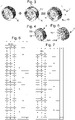
- the figures 6 and 7 detail a non-limiting coding system used for the embodiment illustrated by the figures.
- Each display is held in the rest position by first elastic return means 311, 312, 313, 314, 316, as detailed below.
- At least one display is movable according to a rotation controlled by the movement of at least one trigger or correction flip-flop 11, 12, 13, 14, 15, 16, which the mechanism 100 includes, when this flip-flop jumps.
- the fall of this trigger rocker is controlled or prohibited by at least one cam 21, 22, 23, 24, 244, 245, 246, 247, which the mechanism 100 comprises, and which is arranged to be driven by a movement of watchmaking.
- At least one trigger or correction flip-flop 11, 12, 13, 14, 15, 16 is arranged to cooperate simultaneously with at least two cams 21, 22, 23, 24, 244, 245, 246, 247, towards which it is returned by second elastic return means 119, 129, 139, 149, 159, 169.
- each trigger or correction rocker 11, 12, 13, 14, 15, 16 is arranged to cooperate simultaneously with at least two cams 21, 22, 23, 24, 244, 245, 246, 247, towards which it is returned by second elastic return means 119, 129, 139, 149, 159, 169.
- At least two trigger or correction flip-flops 11, 12, 13, 14, 15, 16, are arranged to cooperate simultaneously in support with the same cam 21, 22, 23, 24, 244, 245, 246, 247 , towards which they are returned by second elastic return means 119, 129, 139, 149, 159, 169.
- the mechanism 100 comprises at least one trigger rocker 11, 12, 13, 14, comprising a first sensor 2111, 2112, 2313, 2314, which is arranged to follow the contour of a rotation control cam 21, 23, which is arranged to cause a jump of a trigger rocker 11, 12, 13, 14, in a particular angular position of this rotation control cam 21, 23.
- At least one trigger rocker 11, 12, 13, 14, is arranged to cooperate simultaneously in support with at least two cams 21, 22, 23, 24, 244, 245, 246, 247, towards which it is returned by second elastic return means 119, 129, 139, 149. More particularly still, each trigger rocker 11, 12, 13, 14, is arranged to cooperate simultaneously in support with at least two cams 21, 22, 23, 24 , 244, 245, 246, 247, towards which it is returned by second elastic return means 119, 129, 139, 149.
- At least one trigger flip-flop 11, 12, 13, 14, is arranged to prevent or authorize the fall of another flip-flop which is a correction rocker 15, 16. More particularly, at least one correction rocker 15, 16, is arranged to control the rotation of the same roller controlled by a trigger rocker 11, 12, 13, 14.
- At least one correction rocker 15, 16, is arranged to control only the rotation of a roller which does not cooperate with any said trigger rocker 11, 12, 13, 14.
- the mechanism 100 comprises at least one prohibition cam 22, 24, 244, 245, 246, 247, which is arranged to prohibit or authorize the fall of such a trigger or correction rocker 11, 12, 13 , 14, 15, 16, including a second sensor 2211, 2212, 2413, 2414, 2415, 2416, is arranged to interfere or not with the prohibition cam 22, 24, 244, 245, 246, 247, depending on the position angle of this prohibition cam 22, 24, 244, 245, 246, 247.
- At least one roller 1, 1A, 1B, 2, 3, 3A, 3B, 4, or combined roller 10 is movable in rotation controlled by a drive mechanism 50M, 50H, independent of trigger or correction rockers 11, 12, 13, 14, 15, 16, and which is driven by another roller 1, 1A, 1B, 2, 3, 3A, 3B, 4, or combined roller 10
- This 50M, 50H drive mechanism will be detailed later.
- the mechanism 100 comprises at least one upstream display assembly 200, the rotations of the upstream rollers 1, 2 of which, which compose it, are controlled by upstream trigger rockers 11, 12, and which is arranged to cooperate with a downstream display assembly 300 to which it is juxtaposed and whose rotations of the downstream rollers 3, 4, which compose it are controlled by downstream trigger rockers 13, 14.
- This mechanism 100 comprises at least one such correction flip-flop 15, 16, which is arranged to cooperate with one of the downstream trigger flip-flops 13, 14, and a flip-flop synchronization mechanism 17 between the correction flip-flops 15, 16, when this mechanism 100 comprises several, for controlling the rotation of at least one display of the downstream display assembly 300 in its appropriate position at the end of a cycle of the upstream display assembly 200.
- the mechanism 100 is arranged to display the value of at least one quantity on a group of displays 90M, 90H, which comprises at least two coaxial displays and juxtaposed to each other, each display being constituted by a roller 1, 1A, 1B, 2, 3, 3A, 3B, 4, or by a combined roller 10.
- At least one group of displays 90M, 90H comprises an internal jump control mechanism for triggering the rotation of one of the displays that comprises the group of displays 90M, 90H, at the end of a cycle of another display which is juxtaposed to it.
- At least one trigger or correction rocker 11, 12, 13, 14, 15, 16 is arranged to cooperate with at least one cam 21, 22, 23, 24, 244, 245, 246, 247, for constitute a jump control mechanism for triggering the rotation of one of the displays at the end of a cycle of another display which is juxtaposed to it.
- the mechanism 100 is more particularly arranged to display the value of at least one quantity on a group of displays 90M, 90H, comprising at least two elementary coaxial displays and juxtaposed to each other, each elementary display being constituted by such roll 1, 1A, 1B, 2, 3, 3A, 3B, 4, or combined roll 10.
- At least one said group of displays 90M, 90H comprises a drive mechanism 50 for triggering the rotation of one of the displays that this group of displays comprises at the end of a cycle of a another display which is juxtaposed to it.
- the mechanism 100 is arranged to display the value of at least two quantities, each quantity being displayed on at least one display or a group of displays 90M, 90H, and all the displays or groups of displays 90M, 90H , are coaxial and juxtaposed in pairs.
- At least one trigger or correction rocker 11, 12, 13, 14, 15, 16 is arranged to cooperate with at least one cam 21, 22, 23, 24, 244, 245, 246, 247, for constitute a jump control mechanism for triggering the rotation of a display of a group of displays 90M, 90H, at the end of a cycle of another display of another group of displays 90M, 90H, which is juxtaposed to it.
- the mechanism 100 comprises a roller synchronization mechanism for triggering the rotation of a said downstream display of a group of displays 90M, 90H, at the end of a cycle of another upstream display.
- Another group of displays 90M, 90H which is juxtaposed to it.
- This mechanism of roller synchronization comprises locking means 1380, 1490, of each downstream trigger rocker 13, 14, arranged for the rotational control of the downstream display 3, resting on lugs 528, 579, carried by the mechanism of drive 50 of the upstream display 2, and the upstream display 2 itself, to block the rotation of each downstream trigger flip-flop 13, 14, during certain display phases, and to synchronize the jump of these at least two display groups 90M, 90H.
- This mechanism of roller synchronization comprises locking means 1380, 1490, of each downstream trigger rocker 13, 14, arranged for the rotational control of the downstream display 3, resting on lugs 528, 579, carried by the mechanism of drive 50 of the upstream display 2, and the upstream display 2 itself, to block the rotation of each downstream trigger
- the mechanism 100 is arranged to display the value of at least two magnitudes on at least two groups of displays 90M, 90H, coaxial and juxtaposed to each other.
- at least one group of displays 90M, 90H comprises at least one trigger or correction flip-flop 11, 12, 13, 14, 15, 16, which comprises a stop support finger 1390, which is arranged for, in certain relative angular positions, cooperating in abutment support with an abutment 528 that comprises a roller 1, 1A, 1B, 2, 3, 3A, 3B, 4, of a group of adjacent displays 90M, 90H, to block its rotation during certain display phases, and to synchronize the jump of the at least two groups of displays 90M, 90H.
- the figures illustrate the mechanical digital display of hours and minutes.
- the display of the minutes is made by a roller of minute units 1, juxtaposed with a roller of tens of minutes 2, in particular visible together through a window of minutes 5.
- the roller of minute units 1 is such a roller combined 10, and comprises an inner roller 1B, visible through the window 1C of the outer roller 1A, as visible on the picture 3 .
- These two rolls 1 and 2 form a first group of displays 90M which is the group of minutes displays.
- the display of the hours is made by a roll of hour units 3, juxtaposed with a roll of tens of hours 4, in particular visible together through an hour window 6.
- the roll of hour units 3 is such a combined roller 10, and comprises an inner roller 3B, visible through the window 3C of the outer roller 3A.
- These two rollers 3 and 4 form a second group of displays 90H which is the group of hour displays.
- the figure 1 illustrates a dial 7 carrying windows 5 and 6 for the minutes and hours, and surmounting a plate 8 which carries the rollers and the other constituents of the mechanism 100.
- rollers pivot around a common axis R; in a particular and non-limiting way, the rockers pivot around a common axis B.
- the picture 3 represents a roller of minute units 1 according to the invention, which is a combined roller 10 which comprises, represented separately from left to right, an inner roller of minutes 1B, an outer roller of minutes 1A with its window of minutes 1C, and the assembly 1 consisting of this inner roller 1B mounted in this outer roller 1A.
- the roll of hour units 3 is similarly constructed, with an inner roll of hours 3B, an outer roll of hours 3A with its window 3C.
- At least one group of displays 90M, 90H comprises at least two rollers, one of which displays as a unit an integer multiple of the value of the unit of the other. More particularly still, each group of displays 90M, 90H comprises at least two rollers, one of which displays as a unit an integer multiple of the value of the unit of the other.
- the display mechanism 100 then comprises, for at least one such group of displays 90M, 90H, at least one drive mechanism 50, for example in the illustrated embodiment a tens of minutes drive mechanism 50M, and a drive mechanism tens of hours 50H.
- the purpose of this drive mechanism 50 is to cause the roller of the multiple to rotate by one position when the roller of the sub-multiple has performed the rotation, or rotations, corresponding to all of its display sequences in the step of the multiple. Except in exceptional circumstances which will be detailed later, the rollers of the multiples (of the tens in the present embodiment) are therefore not driven by rockers, but by such a drive mechanism 50.
- This drive mechanism 50 here a tens of minutes drive mechanism 50M, or a tens of hours drive mechanism 50H, is driven by the sub-multiple roller, here the units roller.
- each group of displays 90M, 90H comprises at least two rollers 1, 1A, 1B, 2, 3, 3A, 3B, 4, connected kinematically by such a drive mechanism 50, which comprises, in the in no way limiting version illustrated by the figures, a Maltese cross 53, 55, which is arranged to be driven in rotation by a pin 109, 319, fixed to the roller of the sub-multiple, and which is fixed in rotation to a star with lugs 51, 56, which is arranged to drive by one of its lugs 511, 561, a cloverleaf 52, 54, which the roller of the multiple carries, by radial grooves 529, 541.
- the roller of the sub-multiple that is- i.e.
- the figure 4 represents a tens of minutes roller 2, which laterally carries a tens of minutes cloverleaf 52, comprising six radial grooves 529, which are arranged to cooperate with a star stud 511 which comprises a stud star 51 coupled with a cross of Malta of minutes 53.
- This tens of minutes clover 52 carries a support lug 528, here in the form of a cubic block, which is arranged to serve as abutment support for a rocker limiting finger 1380 that comprises the rocker of triggering of the hours of the inner roller 13, as will be explained later.
- the cloverleaf 52, 54, or the roll of the multiple carries such a support lug which is arranged to serve as abutment support for a rocker limiting finger that includes a trigger rocker 11, 12 , 13, 14.
- the lug star 51, 56 of the drive mechanism 50 of the upstream display 2 is advantageously arranged to drive in rotation, around an axis parallel to its own, a drive cloverleaf 57, which carries a stop pin of Rocker 579 arranged to serve as abutment support for a rocker abutment finger 1490 that includes a trigger rocker 11, 12, 13, 14.
- the figure 5 represents a roll of the tens of hours 4, which similarly bears a trefoil 54, visible on the figure 45 , and whose shaft has a square drive 4160, and which laterally carries three tenons 72 or planet carrier pivots for a release mechanism 70 explained below.
- This disengagement mechanism 70 has the function of disengaging a drive mechanism 50, to allow the position correction of a roller 1, 1A, 1B, 2, 3, 3A, 3B, 4, directly by a correction rocker 15 , 16, and not by a drive mechanism 50.
- the mechanism 100 advantageously comprises at least one combined roller 10, of which an inner roller 1B, 3B, is arranged to be driven in rotation by a rocker for triggering the inner roller 11, 13, and whose outer roller 1A, 3A, is arranged to be driven by a trigger rocker of the outer roller 12, 14, or by a first correction rocker 15.
- a combined roller 10 is a sub-multiple roller.
- the inner roller 1B, 3B is again arranged to be driven in rotation by the first correction rocker 15, at certain predetermined instants and driven by a twenty-four-hour mobile 24 driven by the movement 500.
- This first rocker of correction 15 is juxtaposed with the release rocker of the inner roller 11, 13, and cooperates with it with the cams of the twenty-four-hour mobile 24.
- the first correction rocker 15 comprises a lateral prominence 151, which rests on a counterbore 135, of the trigger rocker of the inner roller 113. This prominence 151 rests on the counterbore 135, shortly before a jump controlled by a cam 21, 23, on which bears a feeler 2111, 2313, which comprises the rocker of triggering of the inner roller 11, 13.
- the correction latch 15 further comprises a drive finger 1501, which is arranged to take place next to a drive finger 1101, 1301, of the inner roller trigger latch. ieur 11, 13, and to cooperate with the same star 411, 413, of this inner roller 1B, 3B, so that, when the trigger rocker of the inner roller 11, 13 falls, at a controlled instant by the cam 21, 23, and for a jump authorized by the twenty-four-hour mobile 24, the first unit correction rocker hour 15 also falls to drive the star wheel 411, 413 in turn, thereby driving the inner roller 1B, 3B twice.
- each roller comprises a shaft, in particular carrying a square, capable of supporting a star for its rotational drive: one sees in particular in the figures the square 4120 for driving the roller 1, the square 4140 of the roller 3, and the square 4160 of roller 4. It should be noted that some rollers are not necessarily driven by rockers: this is the case here of the tens of minutes roller 2, which is driven by a drive mechanism tens of minutes 50M to Maltese cross.
- the figure 6 represents a coding of the minutes display, according to which is constructed the particular, non-limiting, variant of the mechanism, which is illustrated by the figures, on the basis of the rollers of the figures 3 and 4 .
- the inner roller 1B, respectively 3B has six positions: 0, 1, 2, 3 , 4, 5, 0.
- the outer roller 1A, respectively 3A has six positions: 5, 6, 7, 8, 9, ().
- the double parentheses or square brackets are used to code the opening that the considered roll has.
- This particular configuration makes it possible to have the largest digits in the minimum bulk, the same driving rocker stroke for the two rollers, and the same star-jumper assembly, as can be seen in the figures which include numerous components. identical elements.
- the double parentheses or brackets correspond to the opening of the roll.
- the table of the figure 6 only shows the display of the minutes “00" to "30", because we notice that there is a periodicity of ten minutes.
- the inner roller 1B also rotates so as to pre-position itself on the value "0" to be ready to display it during the next ten.
- the minute display requires a minute cam 21, and a ten minute cam 22.
- One line corresponds to one hour.
- the table of the figure 7 shows the hour display "00" to "24".
- column 4 and column 5 of this table of hours have a periodicity of twelve hours.
- the hour display requires a 23-hour cam, and a twelve-hour cam (columns 4 and 5 of the table in the figure 7 ) which will be described here in the form of a first twelve-hour cam 244, corresponding to column 4 of the table of the figure 7 , and a second twelve-hour cam 245 corresponding to column 5 of the table of the figure 7 , a twenty-four hour cam 246 (column 6 of the table of the figure 7 ), and a correction cam 247 (column 7 of the table of figure 7 ) here comprising a notch 249.
- a single twenty-four-hour mobile 24 groups the twelve-hour, twenty-four-hour, and correction cams, as seen on the figure 27 .
- the tens of minutes roller 2 is not connected to a star in the present application; however, a different coding of the rollers could require it, in which case its case is to be treated similarly to the tens of hours roller 4 for its cooperation with a correction flip-flop 16 presented later.
- This tens of minutes 2 roller laterally carries a 52 trefoil for its drive by a Maltese cross 50M tens drive mechanism.
- the tens-of-hours roller 4 laterally carries a trefoil 54 similar to that carried by the tens-of-minutes roller 2, and comprising radial grooves 541; this cloverleaf 54 is integral with a self-locking wheel 73 of a declutching mechanism 70, in the teeth of which planet wheels 71 mounted loosely on the tenons or planet carrier pivots 72 of the figure 5 , to cause the rotation of this roller for tens of hours 4 by clutching this self-locking wheel 73, while the disengagement of the satellites 71 causes the clutch to be disengaged.
- the unit rollers 1, 3, carry pins 109, 319, which are arranged to cooperate with Maltese crosses of minutes 53, 55, for driving the tens rollers 2, 4, during most passages , apart from special passages at certain times, which will all be detailed later.
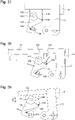
- the figures 9 to 30 expose the passage of minutes. It shows the operation of the minute trigger rocker 11, pivoting about a rocker axis B, for controlling the inner roller 1B of the combined roller of the minute units 1.
- This rocker 11 is subjected to the action of a return spring 119, which tends to press a drive finger 1101, which rocker 11 comprises, on a star 411 which this inner roller 1B comprises, and which is itself subjected to the return torque of a jumper 311 for holding it in the rest position.
- Rocker 11 carries, between its pivot and its distal drive finger 1101, on the one hand a ten-minute feeler finger 2211, which is arranged to cooperate in support with a ten-minute cam 22 which is a cam with a straight edge slot type, and on the other hand a minute feeler roller 2111, which is arranged to rest on the substantially helical track of a minute cam 21, visible on the figure 15 .
- This substantially helical track makes it possible to raise the feeler of each rocker which follows this cam, before its jump.
- the feeler is in particular a ruby or similar roller, to reduce friction.
- This minutes cam 21 includes a device to avoid any recoil at the moment of the jump when the feeler roller 2111 leaves the high point of the cam 21, which is its position on the figure 9 .
- the figure 16 illustrates this device: the cam 21 itself pivots on a cam base 210, a pin 212 secured to the cam 21 slides in a bean-shaped groove 211, which limits the stroke.
- the pin 212 and therefore the cam 21 is ejected tangentially a little further into the groove 211, and drops the rocker 11, and any parasitic backward movement is avoided.
- the figure 10 illustrates the passage of the minute unit, when the ten-minute feeler finger 2211 is not stopped by the relief of the ten-minute cam 22, and just after the jump of the feeler roller 2111, when the fall of the rocker 11 has just driven star wheel 411 of roller 1B which has turned one position.
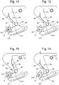
- the figures 11 to 14 are details of the sequence of cooperation between on the one hand the drive finger 1101, which forms a movable assembly 80 pivotally mounted on a pivot 84 and which comprises an elastic blade 81 movable between two front 82 and rear 83 stops, and on the other hand the star 411 of roll 1B.
- the elastic blade 81 bears against a first front stop 82 located on the star 411 side.
- first stop 82 and the finger begins to pivot, its blade 81 approaches the second rear stop 83.
- the star 411 pivots, and the rocker 11 accompanies the star 411 over approximately two thirds of its pitch before reaching its stop, which ensures the passage of the top of jumper 311.
- the finger 1101 is free, until the return of the blade 81 in support on the first limit stop 82; the blade 81 is weaker than the jumper 311 of the star 411, the blade 81 bends to pass the top of the star 411, which therefore cannot be driven again by the finger 1101.
- the figure 18 shows that 21 minutes cam, comprises a substantially helical track, wide enough to be traveled by both feeler rollers 2111 and 2112 that comprise two neighboring rockers 11 and 12.
- the figure 17 shows, together, this minute trigger rocker for the control of the inner roller 11, juxtaposed with the minute trigger rocker for the control of the outer roller 12, the feeler rollers 2111 and 2112 of which thus run along this same helical track of the cam 21, and whose ten-minute feeler fingers 2211 and 2212 are both arranged to cooperate with the same ten-minute cam 22, which authorizes or prohibits the fall of the respective rocker 11 or 12.
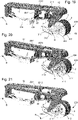
- the figure 19 represents the same set represented in the position it occupies a few seconds before the jump, in a display position "04" of the minutes, with reference to the table of the figure 6 , with the display of the unit of minutes "4", where the outer reel 1A presents its aperture 1C (column 2 of the table), while the inner reel 1B presents the number 4 (column 3 of the table); the mechanism is ready to move to a global display position "05” with a display of units "5", where the outer roller 1A shows the number 5 (column 2), while the inner roller 1B returns to a position where it presents the number 0 (column 3) and is thus ready to anticipate the transition to the following ten minutes where the inner roller 1B will present its number 0 in the window 1C of the outer roller 1A.
- the figure 20 is the situation after the jump, in a display configuration of the value "05" where neither of these two flip-flops 11 and 12 is stopped by the ten-minute cam 22.
- the figure 21 represents the same set after the jump, in another display position, of the value "6", where the inner roller 1B has not rotated and has remained in its display position, because the rocker 11 corresponding to the display of the inner roller 1B is stopped by the ten-minute cam 22, its feeler finger 2211 being in abutment on the notch of the ten-minute cam 22, and therefore the inner roller 1B does not rotate, and only the rocker 12 relating to the outer roller 1A falls and rotates the latter.
- the figures 22 and 23 illustrate the ten-minute drive mechanism 50M, the principle of which is also used for triggering the ten hours in the other group of hour displays 90H.
- This mechanism surrounds the group of displays 90M comprising the combined roller of the units of minutes 1, and the simple roller of the tens of minutes 2; this mechanism is mobile with an axis parallel to the common axis R to the shafts of the various rollers, and comprises, on the side of the combined roller of the minute units 1, a Maltese cross of the minutes 53, whose grooves 531 are arranged to cooperate with piece 109, visible on the figure 17 , that carries this roll 1, and, on the side of the roll of the tens of minutes 2, and fixed in rotation with this Maltese cross of the minutes 53, a star with lugs 51, the lugs 511 of which are arranged to cooperate with the grooves 529 of the cloverleaf of the tens of minutes 52 of the figure 4 .
- the figures 24 and 25 illustrate the passage of a dozen.
- the figure 24 represents the same set, represented in the position it occupies a few seconds before the jump, in global display position "09” with a display position of the minute unit "9", where the outer roller 1A presents the number 9 (column 2), while the inner roll 1B has the number 0 (column 3); the mechanism is ready to move to a global display position "10", where the tens roller, hitherto in display position "0", will move to position "1" (column 1), while , at the level of the combined roller of units 1, the outer roller 1A will present its aperture 1C (column 2) through which the inner roller 1B will continue, without rotation, to present the display "0" (column 3); a groove 531 of the Maltese cross of the minutes 53 of the units of minutes cooperates with the piece 109 of the reel of the units 1.
- the figure 25 represents the same set after the jump, in a global display configuration "10" where neither of the two flip-flops 11, 12 is stopped by the ten-minute cam 22; the outer reel 1A of the combined reel of 1 minute units rotated, and its 109 peg caused the 53 minute Maltese cross to rotate, which at the other end caused the ten minute clover to rotate 52 , and therefore of the ten-minute roll 2.
- the display and passage of the hours is done in a similar way.
- the group of 90H hour displays has a display roller of 3 hour units, and a display roller of tens of hours 4.
- a drive mechanism of the tens of hours 50H surrounds this group of 90H displays, as with minutes, and works similarly to minutes;
- a rocker for triggering the hours of the inner roller 13 and a rocker for triggering the hours of the outer roller 14 are also juxtaposed, and are arranged to cooperate with a single hour cam 23, and with a combined twenty-four-hour wheel set 24, which comprises in particular a twenty-four hour cam and a twelve hour cam.
- the operation of the passage of hours is similar to the passage of minutes described above, the only significant variant being the presence of a twelve-hour cam, instead of a ten-minute cam.
- the invention can be used for any combination of displays, one of which displays a multiple of the other, and for any display range.
- coding of the various rollers, and the nature of the cams and of the correction rockers, are to be adapted to each specific case.
- the reels can occupy four, or six, or ten, or even twelve positions
- the multiplier coefficient between two reels of the same group of displays can also be four, or six, or ten, twelve positions, or other, for other displays such as calendar, moon phases, tides, or other.
- the drive mechanism 50 can also generate the drive of the multiple roller with coefficients different from ten, for example four, six, twelve, or other.
- the twenty-four-hour mobile 24 here groups together a first twelve-hour cam 244 of the trigger rocker of the inner hour roller 13, a second twelve-hour cam 245 of the trigger rocker of the outer roller of hours 14 , and a twenty-four hour cam 246, and a correction cam 247, for the management of certain time passages: midnight, one o'clock in the morning, and in particular to guarantee the passage from the display "4" to the display “0”.
- This correction cam cooperates with correction flip-flops 15 and 16 detailed below.
- the invention requires the presence of a synchronization mechanism between the display of the minutes and that of the hours, in particular at current times, that is to say other than at midnight.
- the mechanical system transmits the instantaneousness of the jump from the units roller to the tens roller, both for the hours and for the minutes, thanks to the respective tens drive mechanism by Maltese cross, trefoil with lugs, and trefoil of coaching.
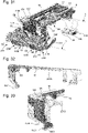
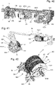
- the figure 28 thus represents, a few minutes before a time change, the triggering rocker of the inner roller of hour units 13, which is similar to the trigger rocker of the inner roller of the minute units 11, and whose feeler finger 2313 has just left the cam of the hours 23.
- This trigger rocker of the inner roller of the hour units 13 comprises a second finger of rocker limitation 1380, which is arranged to cooperate in abutment abutment with a lug 528 that includes the cloverleaf 52 of the tens-of-minutes roller 2, which prevents the fall of the trigger rocker of the inner hour units roller 13 as long as that the tens of minutes roller 2 has not completed its rotation.
- the figure 29 represents, at the same time as the figure 28 , the same mechanism, of which the trigger rocker of the inner roller of the hour units 13 is not represented, in order to allow the vision of the trigger rocker of the outer roller of the hour units 14, whose feeler finger 2314 also just left the 23 hour cam; this release rocker of the outer roll of the hour units 14 also comprises a second rocker abutment finger 1490, which is arranged to cooperate in abutment support with a lug 579 that comprises a drive cloverleaf 57, kinematically linked to the system Maltese cross of minutes, and which, in the same way, prevents the fall of the rocker for triggering the outer roller of 14 hour units as long as the Maltese cross of minutes 53 has not completed its rotation.
- the driving trefoil 57 is in particular rotatably mounted on a shaft parallel to that of the Maltese cross of minutes 53, as visible on the figure 29 .
- the figure 31 shows the entire mechanism relating to the hours, which incorporates a 15-hour units correction rocker which is juxtaposed with the trigger rocker of the hour units inner roller 13, and a tens-of-hours correction rocker 16 which is juxtaposed with the trigger rocker of the outer roller of the hour units 14; the assembly is shown in position at 11:59 p.m.
- This figure also shows the two tens drive mechanisms.
- the table of the figure 7 shows that the passage of tens of hours, in particular from position "23” to position "00”, does not follow the classic pattern of passages from “03” to "04” and from "13” to "14", because if the 'we followed the same logic, changing the display would change from "23” to "24” when we want to display "00” permanently, and not “24", for displays in the first hour of the morning ; this does not exclude a variant with a very brief transitional display “24” “00”, between the normal displays “23” “59” and “00” “00”, which each remain visible for approximately one minute.
- the figures 32 and 33 represent the hour units correction rocker 15, which comprises a lateral prominence 151, which rests on a counterbore 135 of the trigger rocker of the inner hour units roller 13, the prominence 151 rests on the counterbore 135 a few minutes before the jump, she is then on standby.
- the hour units correction latch 15 comprises a drive finger 1501, which is arranged to take place next to the drive finger 1301 of the trigger latch of the inner hour units roller 13, and to cooperate with a same drive star 413 of the inner roll of the hour units 3B.
- this 15 hour units correction flip-flop also drops when passing midnight, driving the 3B hour inner roller twice , and to allow the passage from the display "3" to the display "0", without going through the display "4"; it is the same at one o'clock in the morning, as visible on the board of the figure 7 .
- the figure 34 represents, together, the hour units correction flip-flop 15, and the tens-hour correction flip-flop 16, which constitute an arrangement allowing, at midnight, the passage from the display "2" to the display " 0”, without the entry into function of the tens drive mechanism by the Maltese cross 55.
- This tens correction rocker at hour 16 falls a few minutes before midnight, and relies on the units correction rocker hour 15, via a synchronizer which is a shaft 17 carried by the tens of hour correction flip-flop 16, which is parallel to the pivot axis B common to the flip-flops, and of which a bearing surface 172 cooperates with a face d press 152 of the hour units correction rocker 15.
- This figure 34 shows, again, the feeler fingers 2415 and 2416 of these two rockers 15 and 16, which are both arranged to cooperate with the twenty-four-hour mobile 24 which authorizes or prohibits the fall of these rockers.
- a correction rocker 15 carries a pivoting hook 154, which cooperates with a hook actuator 138 carried by the trigger rocker 11, 13, driving this inner roller 1B, 3B, so that, at the end of the travel of the trigger rocker 13, its hook actuator 138 releases the hook 154, and authorizes the fall of the correction rocker 15, which is released by the twenty-four-hour mobile 24, for driving the inner roller 1B, 3B.
- the figure 35 represents, together and juxtaposed, the trigger rocker for the inner hour roll 13, and the hour units correction rocker 15, the combination of which authorizes particular display passages, including the direct passage of the inner hour roller 3B from position “3" to position "0" without rotation of the outer roller 3A, and the passage of the tens of hours roller from position "2" to position "0” without rotating the Maltese cross of 55 hours of the tens drive mechanism.
- the hour units correction rocker 15 carries a hook swivel 154, which cooperates with a hook actuator 138 carried by the trigger rocker for the inner hour roller 13.
- the hour units correction flip-flop 15 includes a feeler finger 2415, which is arranged to cooperate with the combined twenty-four-hour mobile 24, and in particular with its outer track; the transition from position "3" to position "4" is conventionally controlled by the drive finger 1301 of the trigger rocker for the inner hour roller 13 while the hour unit correction rocker 15 is immobilized by this hook 154.
- the hook actuator 138 is arranged to push an oblique track 158 of the pivoting hook 154.
- the rocker 15 carries a pin support finger 152 which carries a locking pin 156, which cooperates with a cylindrical track 155 of the hook 154 during a game of the angular stroke of the latter, and which escapes it at the end of the angular stroke of the hook under the thrust of the hook actuator 138.
- the hook actuator 138 bears against the oblique track 158 of the hook 154, and neither of the two rockers 13 and 15 has pivoted.
- the figure 38 illustrates the beginning of the drop of the trigger rocker for the inner roll of hours 13, for the passage from position “3” to position “4”; the hook actuator 138 pushes back the oblique track 158, and causes the hook 154 to pivot, which again cooperates with its pin 156 at the level of its concentric cylindrical track 155, immobilizing the hour units correction rocker 15.
- the figure 39 illustrates the end of the drop of the trigger rocker for the inner roll of hours 13 for the passage from position "3" to position "4"; the hook actuator 138 pushes back the oblique track 158 of the hook 154, and causes the hook 154 to pivot, which escapes its pin 156, releasing the hour units correction rocker 15, which, also released by the twenty -four hours 24, can pivot and drive the roller by its drive finger 1501 interior of the hour units 3B, which has just passed briefly into position "4" under the action of the fall of the trigger rocker for the interior roll of the hours 13, towards the "0"position; the twenty-four-hour mobile 24 is arranged to allow the fall of the hour unit correction flip-flop 15 only twice a day, at midnight and at one o'clock in the morning.
- the twenty-four hour cam 247 has a notch 249 corresponding to this time range.
- the hour units correction rocker 15 remains on the upper part of the twenty-four hour cam 247, which prevents it from falling and prevents it from rotating the star wheel 413 of the inner roller 3B units of hour.
- the passage of the tens of hours roller 4 from position "2" to position "0" requires the intervention of the tens of hours correction rocker 16, already presented on the figure 34 .
- the tens of hour correction flip-flop 16 cooperates with a twenty-four-hour cam 246, located on the twenty-four-hour mobile 24, in order, each day at midnight, to release this flip-flop 16 to drive a linked star 416 to the tens of hours roller 4, to move it from position "2" to position "0".
- this release mechanism 70 comprises a self-locking wheel 73 with satellites 71, similar to that of an automatic reverser, to allow the rotation of the tens-of-hour roller 4 independently with respect to the drive clover linked to the 55-hour Maltese cross of the tens drive mechanism, which itself is blocked.
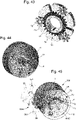
- the figure 43 shows the trefoil 54 of the tens of hours roller 4, under which trefoil 54 we see this self-locking wheel 73 cooperating with satellites 71, in particular and not limited to three satellites 71 which pivot on three tenons or pivots 72 carried by the tens roller of 4 hours.
- the figure 45 illustrates a classic ten passage.
- the outer roller 3A of the hour units moves from position "9" to position "0"
- it activates the Maltese cross at 55 hours, which rotates the trefoil 54 integral with the self-locking wheel 73
- the satellites 71 have a particular non-reversible shape, and lock in the teeth of the self-locking wheel 73, which causes the rotation of the roller for tens of hours 4
- the self-locking wheel 73 and the tens roller 4 rotate clockwise as seen in the figure, and at least one satellite 71 is braced with the teeth of the self-locking wheel 73.
- release mechanism 70 can take other constructive forms, for example with a mechanism of the freewheel type, authorizing rotation in one direction, and imposing in the other direction a clutch by blocking a ball on the wall of a chamber in which this marble is enclosed, or whatever.
- This disengagement mechanism 70 may thus comprise two inputs.
- the jumping roller clockwork display mechanism 100 makes it possible to have, under a small volume, an original display, which can constitute a main display or a secondary display, alone, or in combination or juxtaposition with other displays.
- a particular application describes below a timepiece 1000, in particular a watch, comprising at least one movement 500 for driving a main display mechanism and a secondary display mechanism.
- the example chosen concerns a space mission to the planet Mars: one of the displays is that linked to the planet Earth and to the duration of terrestrial days and hours, while the other display, made with a clockwork display mechanism jumping roller 100 according to the invention, is linked to the planet Mars, and to the duration of Martian days and hours.
- the duration of a Martian solar day is 24.659790 Earth hours (close to 24 hours and 40 Earth minutes).
- a suitable timer which uses mobiles with reasonable numbers of teeth for use in a watch, has a 22-tooth earth roadway, which completes one revolution, when a 36-tooth timer pinion completes 0.6111 revolutions, and a 43-tooth timer wheel, which cooperates with a 27-tooth Martian roadway, which then performs 0.973251028806584 revolutions.
- the error related to this timer is small, about 6.733. 10 -6 , which corresponds to 4.10 -4 Earth minutes, or 0.02424 Earth seconds, or 0.58171 second per Earth day.
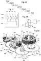
- the figure 49 schematizes the connection between the Earth roadway 610 and the Mars roadway 630 via the timer mobile 620, which comprises the timer pinion 621 and the timer wheel 622.
- the figure 50 is a perspective view of the multiplier/demultiplier gear train 640, which comprises, from the Mars roadway 630 on which the hours cam 23 is located, a first reduction gear train 641 to drive the twenty-four-hour mobile 24, and a second gear train multiplier 642 to drive the minutes cam 21 and the ten minutes cam 22.
- This first reduction gear train 641 comprises a timer wheel set for the hours 643, a twelve hour wheel set 644, and the twenty-four hour wheel set 24.
- This second multiplier gear train 642 comprises an intermediate wheel set 645, a multiplier wheel set 646, a minute wheel set 647 carrying the minute cam 21, and a ten-minute wheel set 648 carrying the ten-minute cam 22.
- the invention is also applicable for a main time display, a secondary display, a second time zone, a chronograph, or any other display.
Landscapes
- Physics & Mathematics (AREA)
- General Physics & Mathematics (AREA)
- Measurement Of Unknown Time Intervals (AREA)
- Adornments (AREA)
- Transmission Devices (AREA)
- Electromechanical Clocks (AREA)
- Electric Clocks (AREA)
- Dental Preparations (AREA)
Abstract
Mécanisme d'affichage d'horlogerie sautant à rouleaux (100), dont chaque afficheur comporte un rouleau (1, 1A, 1B, 2, 3, 3A, 3B, 4) et/ou un rouleau combiné (10) comportant deux rouleaux (1A, 1B, 3A, 3B) intérieurs l'un à l'autre, maintenu en position de repos par des premiers moyens de rappel élastique (311, 312, 313, 314, 316), au moins un afficheur est mobile en rotation commandée par le mouvement d'au moins une bascule (11, 12, 13, 14, 15, 16) dont la chute est commandée ou interdite par au moins une came (21, 22, 23, 24, 244, 245, 246, 247) entraînée par un mouvement (500), et au moins une bascule de déclenchement ou de correction (11, 12, 13, 14, 15, 16) est agencée pour coopérer simultanément en appui avec deux cames (21, 22, 23, 24, 244, 245, 246, 247) vers lesquelles elle est rappelée par des deuxièmes moyens de rappel élastique (119, 129, 139, 149, 159, 169).
Description
L'invention concerne un mécanisme d'affichage d'horlogerie sautant à rouleaux.The invention relates to a roller jumping clockwork display mechanism.
L'invention concerne encore une pièce d'horlogerie, notamment une montre, comportant au moins un mouvement agencé pour entraîner des cames que comporte un tel mécanisme d'affichage d'horlogerie sautant à rouleaux.The invention also relates to a timepiece, in particular a watch, comprising at least one movement arranged to drive cams that comprises such a jumping roller clockwork display mechanism.
L'invention concerne le domaine des mécanismes d'affichage d'horlogerie.The invention relates to the field of timepiece display mechanisms.
Il est souvent difficile de faire cohabiter différents affichages sur une pièce d'horlogerie, surtout quand elle est de dimensions réduites comme une montre.It is often difficult to make different displays cohabit on a timepiece, especially when it is of small size like a watch.
Et il importe de distinguer facilement un affichage principal d'un affichage secondaire, sans aucun risque de confusion.And it is important to easily distinguish a primary display from a secondary display, without any risk of confusion.
Une solution consiste à recourir à des afficheurs classiques, tels qu'aiguilles ou disques, pour un premier affichage, et à un afficheur à rouleaux pour un deuxième affichage. Toutefois un affichage à rouleaux pour montre nécessite un volume conséquent, et est difficile à implanter dans une montre. De plus, afin d'éviter des doutes d'interprétation au changement d'heure ou de jour, il est préférable de réaliser un affichage sautant instantané, qui est plus complexe. Ces contraintes sont encore amplifiées quand ce deuxième affichage concerne des grandeurs avec des unités différentes de celles du premier affichage, ce qui nécessite un mécanisme de conversion compliquant encore la construction de la montre.One solution consists in using conventional displays, such as needles or discs, for a first display, and a roller display for a second display. However, a roller display for a watch requires a substantial volume, and is difficult to install in a watch. Furthermore, in order to avoid interpretation doubts when the time or day changes, it is preferable to produce an instantaneous jumping display, which is more complex. These constraints are further amplified when this second display concerns magnitudes with units different from those of the first display, which requires a conversion mechanism which further complicates the construction of the watch.
L'invention se propose de développer un affichage à rouleaux pour montre à saut instantané, offrant ainsi les meilleures garanties d'affichage, et d'encombrement raisonnable, compatible avec le volume d'une montre.The invention proposes to develop a roller display for an instantaneous jump watch, thus offering the best guarantees of display, and of reasonable size, compatible with the volume of a watch.
L'invention est exposée pour le cas particulier d'une montre pour mission spatiale vers la planète Mars, où l'affichage principal concerne l'horaire terrestre, tandis que l'affichage secondaire à rouleaux concerne l'horaire martien.The invention is described for the particular case of a watch for a space mission to the planet Mars, where the main display relates to the terrestrial time, while the secondary roller display relates to the Martian time.
A cet effet, l'invention concerne un mécanisme d'affichage d'horlogerie sautant à rouleaux selon la revendication 1.To this end, the invention relates to a roller jumping clockwork display mechanism according to
L'invention concerne encore une pièce d'horlogerie, notamment une montre, comportant au moins un mouvement agencé pour entraîner des cames que comporte un tel mécanisme d'affichage d'horlogerie sautant à rouleaux.The invention also relates to a timepiece, in particular a watch, comprising at least one movement arranged to drive cams that comprises such a jumping roller clockwork display mechanism.
D'autres caractéristiques et avantages de l'invention apparaîtront à la lecture de la description détaillée qui va suivre, en référence aux dessins annexés, où une réalisation particulière de l'invention est illustrée pour le cas particulier et non limitatif de l'affichage digital mécanique des heures et des minutes, sur quatre digits, à saut instantané, et où :
- la
figure 1 représente, de façon schématisée et en perspective, un cadran portant des guichets des minutes et des heures au travers desquels sont visibles des groupes de rouleaux d'affichage, respectivement des minutes et des heures, lequel cadran surmonte une platine qui porte ces rouleaux et les autres constituants d'un mécanisme d'affichage sautant, à saut instantané, selon l'invention; - la
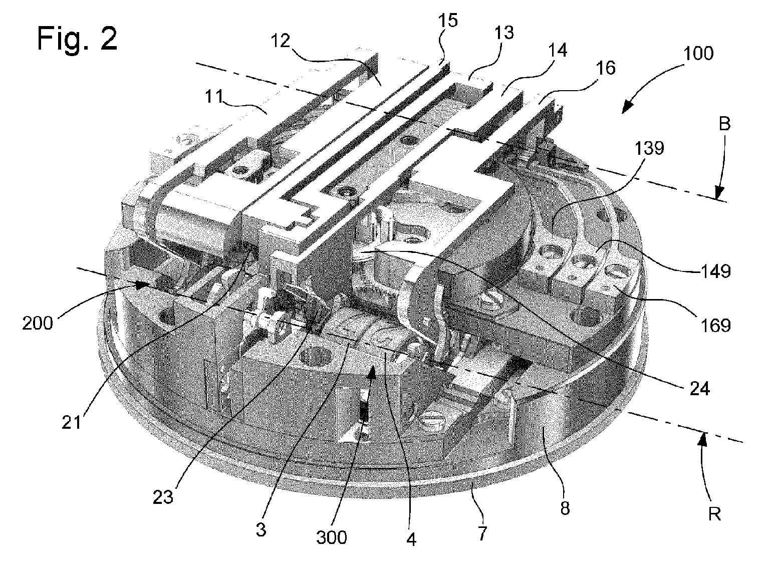
figure 2 est le contrechamp de lafigure 1 et montre le dessous du même mécanisme, avec en particulier les différentes bascules de déclenchement ou de correction, et une partie de leurs ressorts de rappel; les rouleaux des heures sont visibles en partie basse vers le milieu de la figure; l'axe commun de pivotement des rouleaux est figuré par un trait mixte; l'axe commun de pivotement des bascules est également figuré par un autre trait mixte; - la
figure 3 représente, de façon schématisée et en perspective, un rouleau des unités de minute selon l'invention, qui est un rouleau combiné qui comporte, représentés séparément de gauche à droite, un rouleau intérieur, un rouleau extérieur avec son guichet, et l'ensemble constitué de ce rouleau intérieur monté dans ce rouleau extérieur; le rouleau des unités d'heure, non illustré, est construit de façon similaire; - la
figure 4 représente, de façon schématisée et en perspective, un rouleau des dizaines de minutes, qui porte latéralement un trèfle des dizaines de minutes comportant six rainures radiales qui sont agencées pour coopérer avec un ergot d'étoile que comporte une étoile à ergots couplée avec une croix de Malte, et qui porte un ergot d'appui, en forme de bloc cubique, agencé pour servir d'appui de butée à un doigt de limitation de bascule; - la
figure 5 représente, de façon schématisée et en perspective, un rouleau des dizaines d'heures, dont l'arbre comporte un carré d'entraînement, et qui porte latéralement trois tenons ou pivots porte-satellite pour un mécanisme de débrayage; - la
figure 6 représente un codage de l'affichage des minutes, selon lequel est construite la variante particulière, non limitative, du mécanisme, qui est illustrée par les figures, sur la base des rouleaux desfigures 3 et 4 ; - la
figure 7 représente un codage de l'affichage des heures, selon lequel est construite la variante particulière, non limitative, du mécanisme, qui est illustrée par les figures, sur la base des rouleaux illustrés auxfigures 3 et 5 ; - la
figure 8 représente, de façon schématisée et en perspective, en partie droite un premier groupe d'afficheurs qui est le groupe d'afficheurs des minutes, et comporte, de droite à gauche, le rouleau des unités de minute de lafigure 3 et le rouleau des dizaines de minutes de lafigure 4 , et, en partie gauche, un deuxième groupe d'afficheurs qui est le groupe d'afficheurs des heures et comporte, de droite à gauche, le rouleau des unités d'heure, analogue à lafigure 3 , et le rouleau des dizaines d'heures de lafigure 5 ; ces quatre rouleaux sont coaxiaux, et chacun d'eux est relié à une étoile maintenue en position de repos par un sautoir; le rouleau des dizaines d'heures porte latéralement un trèfle similaire à celui que porte le rouleau des dizaines de minutes, ce trèfle est solidaire d'une roue autobloquante d'un mécanisme de débrayage, dans la denture de laquelle peuvent se bloquer des satellites montés fous sur les tenons ou pivots porte-satellite de lafigure 5 , pour provoquer la rotation de ce rouleau des dizaines d'heures par embrayage de cette roue, tandis que le dégrènement des satellites provoque le débrayage; - la
figure 9 représente, de façon schématisée et en vue de côté, la commande de la bascule de déclenchement des minutes, pour la commande du rouleau intérieur du rouleau combiné des unités de minute; cette bascule est pivotée en partie inférieure gauche de la figure, et soumise à l'action d'un ressort de rappel qui tend à appuyer un doigt d'entraînement, que comporte la bascule, sur une étoile que comporte ce rouleau intérieur et qui est elle-même soumise au couple de rappel d'un sautoir pour son maintien en position de repos; cette bascule porte, entre son pivot et son doigt d'entraînement distal, d'une part un doigt palpeur de dix minutes, qui est agencé pour coopérer en appui avec une came de dix minutes qui est une came à bord droit de type créneau, et d'autre part un galet palpeur de minutes, qui est agencé pour prendre appui sur la piste sensiblement hélicoïdale d'une came des minutes, laquelle came comporte un dispositif pour éviter tout recul à l'instant du saut quand le galet palpeur quitte le point haut de la came, qui est sa position sur cette figure; - la
figure 10 représente le passage de l'unité de minute, par le mécanisme de lafigure 9 , quand le doigt palpeur de dix minutes n'est pas arrêté par le relief de la came de dix minutes, et juste après le saut du galet palpeur, quand la chute de la bascule vient d'entraîner l'étoile du rouleau qui a tourné d'une position; - les
figures 11 à 14 sont des détails, en représentation en vue de côté, du côté opposé par rapport auxfigures 9 et 10 , de la séquence de coopération entre le doigt entraîneur, qui est monté pivotant et comporte une lame élastique mobile entre deux butées, et l'étoile du rouleau; - la
figure 11 est la position de repos, similaire à lafigure 9 , avant que la bascule ne descende; la lame élastique est en appui sur une première butée située du côté de l'étoile; - la
figure 12 montre, lors de la descente de la bascule, la prise de contact du doigt avec l'étoile, la lame du doigt quitte la première butée et le doigt commence à pivoter dans le sens de la flèche; - la
figure 13 montre le contact entre la lame du doigt et la deuxième butée, et l'entraînement de l'étoile qui pivote, et la bascule accompagne l'étoile sur environ deux tiers de son pas avant d'atteindre sa butée, ce qui assure le passage du sommet du sautoir; - la
figure 14 montre la remontée de la bascule, pendant laquelle le doigt est libre, jusqu'au retour de la lame du doigt en appui sur la première butée de limitation; la lame est plus faible que le sautoir de l'étoile, la lame fléchit pour passer le sommet de l'étoile, qui ne peut donc être entraînée à nouveau par le doigt; - les
figures 15 et 16 illustrent la came des minutes, de façon schématisée et en perspective vue de dessus et de dessous: cette came des minutes est en deux parties, dont l'une comporte une piste sensiblement hélicoïdale, suffisamment large pour être parcourue à la fois par deux galets palpeurs que comportent deux bascules voisines, cette partie supérieure est mobile en rotation par rapport à une partie inférieure, avec une mobilité angulaire limitée par la coopération d'une goupille solidaire de la partie came, avec une rainure oblongue en haricot qui limite l'angle de liberté: ainsi, lors de la chute, quand le galet palpeur de la bascule passe le sommet de la came, il n'y a pas d'effet de recul, et la chute de la bascule est possible pour entraîner l'étoile du rouleau, dans un saut instantané; - la
figure 17 représente, de façon schématisée et en perspective, cette bascule de déclenchement des minutes pour la commande du rouleau intérieur, juxtaposée avec la bascule de déclenchement des minutes pour la commande du rouleau extérieur, dont les galets palpeurs parcourent ensemble cette même piste hélicoïdale de la came, et dont les doigts palpeurs de dix minutes sont tous deux agencés pour coopérer avec la même came de dix minutes, qui autorise ou interdit la chute de la bascule; cette figure montre également les ressorts de rappel de ces deux bascules; le rouleau des unités, à gauche sur la figure, porte un pion qui est destiné à coopérer avec une rainure d'une croix de Malte que comporte un mécanisme d'entraînement des dix minutes; - la
figure 18 est un détail qui représente, de façon schématisée et en perspective, les galets palpeurs des deux bascules voisines, qui parcourent ensemble cette même piste hélicoïdale de la came des minutes; - la
figure 19 est similaire à lafigure 17 , et représente le même ensemble représenté dans la position qu'il occupe quelques secondes avant le saut, dans une position d'affichage de l'unité de minutes « 4 », où le rouleau extérieur présente son guichet, tandis que le rouleau intérieur présente lechiffre 4; le mécanisme est prêt pour passer à une position d'affichage « 5 », où le rouleau extérieur présente lechiffre 5, tandis que le rouleau intérieur repasse dans une position où il présente lechiffre 0 et est ainsi prêt pour anticiper le passage à la dizaine de minutes suivantes où le rouleau intérieur présentera sonchiffre 0 dans le guichet du rouleau extérieur; aucune de ces deux bascules n'est ici arrêtée par la came des dix minutes; - la
figure 20 est similaire à lafigure 19 , et représente le même ensemble après le saut, dans une configuration d'affichage intermédiaire où aucune de ces deux bascules n'est arrêtée par la came des dix minutes, laquelle peut s'opposer à la chute d'une des bascules qui la parcourt, pour laisser tourner ou non le rouleau intérieur ou le rouleau extérieur; de ce fait chaque bascule a entraîné son rouleau respectif, et, simultanément, le rouleau extérieur et le rouleau intérieur ont tourné d'une position; - la
figure 21 est similaire à lafigure 20 , et représente le même ensemble après le saut suivant pour le passage de l'affichage de la position d'affichage « 5 » à la position d'affichage « 6 », où seul le rouleau extérieur tourne, tandis que le rouleau intérieur reste dans la position où il présente le chiffre « 0 »; en effet le rouleau intérieur n'a pas tourné, et est resté dans sa position d'affichage, car la bascule correspondant à l'affichage du rouleau intérieur est arrêtée par la came des dix minutes, son doigt palpeur étant en butée sur le créneau de la came des dix minutes, et de ce fait le rouleau intérieur ne tourne pas, et seule la bascule relative au rouleau extérieur chute et fait pivoter ce dernier; - les
figures 22 et 23 représentent, de façon schématisée et en perspective vue de deux côtés opposés, le mécanisme d'entraînement des dix minutes, qui entoure le groupe d'afficheurs comportant le rouleau combiné des unités de minutes, et le rouleau simple des dizaines de minutes; ce mécanisme est un mobile d'axe parallèle à l'axe commun aux arbres des différents rouleaux, et comporte, du côté du rouleau combiné des unités de minutes, une croix de Malte dont les rainures sont agencées pour coopérer avec le pion, visible sur lafigure 17 , que porte ce rouleau combiné des unités, et, du côté du rouleau des dizaines de minutes, et solidaire en rotation avec cette croix de Malte, une étoile à ergots dont les ergots sont agencés pour coopérer avec les rainures du trèfle des dizaines de minutes de lafigure 4 ; - la
figure 24 est similaire à lafigure 20 , et est complétée avec le mécanisme d'entraînement des dix minutes desfigures 22 et 23 , et représente le même ensemble représenté dans la position qu'il occupe quelques secondes avant le saut, dans une position d'affichage de l'unité de minutes « 9 », où le rouleau extérieur présente lechiffre 9, tandis que le rouleau intérieur présente lechiffre 0; le mécanisme est prêt pour passer à une position d'affichage « 10 », où le rouleau des dizaines, jusque-là dans la position d'affichage « 0 », passera dans la position « 1 », tandis que, au niveau du rouleau combiné des unités, le rouleau extérieur présentera son guichet au travers duquel le rouleau intérieur continuera, sans rotation, à présenter lechiffre 0; une rainure de la croix de Malte des unités de minutes coopère avec le pion du rouleau des unités; - la
figure 25 est similaire à lafigure 24 , et représente le même ensemble après le saut, dans une configuration d'affichage intermédiaire où aucune de ces deux bascules n'est arrêtée par la came des dix minutes; le rouleau extérieur du rouleau combiné des unités de minutes a pivoté, et son pion a entraîné la croix de Malte en rotation, ce qui, à l'autre extrémité, a entraîné la rotation du trèfle des dix minutes, et donc du rouleau des dix minutes; - la
figure 26 représente, de façon similaire à lafigure 24 , l'ensemble des afficheurs d'heures et de minutes de lafigure 8 , et les bascules de déclenchement propres au mécanisme des heures, lequel comporte un rouleau combiné des heures avec un rouleau intérieur dans un rouleau extérieur, comme celui des minutes, et un rouleau des dizaines d'heures; un mécanisme d'entraînement des dix heures entoure ce groupe d'afficheurs, comme dans le cas des minutes, et fonctionne de façon similaire à celui des minutes; deux bascules de déclenchement pour le rouleau intérieur des heures et pour le rouleau extérieur des heures sont également juxtaposées, et sont agencées pour coopérer avec une came des heures unique, et avec un mobile combiné de vingt-quatre heures comportant une came de vingt-quatre heures et une came de douze heures; le fonctionnement des passages d'heures est similaire au passage des minutes exposé auxfigures 9 à 25 , la seule variante importante étant la présence d'une came de douze heures (analogue à la came des dix minutes en ce qui concerne son fonctionnement); - la
figure 27 représente, de façon schématisée et en perspective, ce mobile de vingt-quatre heures, qui regroupe une came de douze heures de la bascule du rouleau intérieur, une came de douze heures de la bascule du rouleau extérieur, et une came de correction pour la gestion de certains passages horaires : minuit, une heure du matin, pour garantir le passage de l'affichage « 4 » à l'affichage « 0 »; cette came de correction coopère avec une bascule de correction détaillée plus loin; - les
figures 28 à 30 illustrent, de façon schématisée, partielle et en perspective, la synchronisation entre l'affichage des minutes et celui des heures aux heures courantes, c'est-à-dire autres qu'à minuit : - la
figure 28 représente, quelques minutes avant un changement d'heure, une bascule de déclenchement du rouleau intérieur des unités d'heure, similaire à son homologue des minutes, et dont le doigt palpeur vient de quitter la came des heures; cette bascule comporte un deuxième doigt, qui est agencé pour coopérer en appui de butée avec un ergot que comporte le trèfle du rouleau des dizaines de minutes, qui empêche la chute de la bascule tant que le rouleau des dizaines de minutes n'a pas effectué sa rotation; - la
figure 29 représente, au même moment que lafigure 28 , le même mécanisme, dont la bascule de déclenchement du rouleau intérieur des unités d'heure n'est pas représentée afin de permettre la vision d'une bascule de déclenchement du rouleau extérieur des unités d'heure, dont le doigt palpeur vient aussi de quitter la came des heures; cette bascule comporte un deuxième doigt, qui est agencé pour coopérer en appui de butée avec un ergot que comporte un trèfle d'entraînement lié cinématiquement au système de croix de Malte des minutes, et qui, de la même façon, empêche la chute de la bascule tant que la croix de Malte des minutes n'a pas effectué sa rotation; - la
figure 30 montre les deux bascules desfigures 28 et 29 , juste après la rotation du rouleau des dizaines de minutes entre sa position « 5 » et sa position « 0 », lors de laquelle rotation les deux ergots quittent le chemin des bascules, ce qui autorise leur chute, et donc l'entraînement du rouleau des unités des heures; - la
figure 31 illustre, de façon similaire à lafigure 26 , le mécanisme relatif aux heures, qui incorpore une bascule de correction des unités d'heure qui est juxtaposée à la bascule de déclenchement du rouleau intérieur des unités d'heure, et une bascule de correction des dizaines d'heure qui est juxtaposée à la bascule de déclenchement du rouleau extérieur des unités d'heure; l'ensemble est représenté en position à 23 heures 59; - la
figure 32 représente, de façon schématisée et en perspective, la bascule de correction des unités d'heure, qui comporte une proéminence latérale, qui s'appuie sur un lamage de la bascule de déclenchement du rouleau intérieur des unités d'heure, et qui comporte un doigt d'entraînement, qui est agencé pour prendre place à côté du doigt d'entraînement de celle-ci, et pour coopérer avec une même étoile d'entraînement du rouleau intérieur des unités d'heure; cette bascule de correction des unités d'heure tombe lors du passage à minuit pour entraîner deux fois le rouleau intérieur des heures, et permettre le passage de l'affichage « 3 » à l'affichage « 0 », sans passer par l'affichage « 4 »; il en est de même à une heure du matin; - la
figure 33 est un détail de la coopération de synchronisation entre ces deux bascules par appui de l'une sur l'autre, la proéminence latérale s'appuyant sur le lamage de la bascule de déclenchement du rouleau intérieur des unités d'heure qui est représentée en transparence; la bascule de correction des unités d'heure chute avec la bascule de déclenchement du rouleau intérieur des unités d'heure quand cette dernière est libérée et tombe; - la
figure 34 représente ensemble, de façon schématisée et en perspective, la bascule de correction des unités d'heure, et une bascule de correction des dizaines d'heure, qui est un des agencements nécessaires pour permettre, à minuit, le passage de l'affichage « 2 » à l'affichage « 0 », sans l'entrée en fonction d'un mécanisme d'entraînement des dizaines par la croix de Malte, comme il sera exposé plus loin; cette bascule de correction des dizaines d'heure tombe quelques minutes avant minuit, et s'appuie sur la bascule de correction des unités d'heure par l'intermédiaire d'un synchronisateur qui est un arbre porté par la bascule de correction des dizaines d'heure parallèle à l'axe de pivotement commun aux bascules, et dont une portée coopère avec une face d'appui de la bascule de correction des unités d'heure; - la
figure 35 représente de façon schématisée et en perspective, ensemble et juxtaposées, la bascule de déclenchement pour le rouleau intérieur des heures, et la bascule de correction des unités d'heure, dont la combinaison autorise des passages d'affichage particuliers, dont le passage direct du rouleau intérieur des heures de la position « 3 » à la position « 0 » sans rotation du rouleau extérieur, et le passage du rouleau des dizaines d'heures de la position « 2 » à la position « 0 » sans faire tourner la croix de Malte du mécanisme d'entraînement des dizaines; pour permettre le passage direct du rouleau intérieur des heures de la position « 3 », via la position « 4 » à la position « 0 » sans rotation du rouleau extérieur, la bascule de correction des unités d'heure porte un crochet pivotant, qui coopère avec un actionneur de crochet porté par la bascule de déclenchement pour le rouleau intérieur des heures; comme sur lafigure 33 , on voit, juxtaposés, les doigts d'entraînement de ces deux bascules, qui sont agencés pour coopérer avec une même étoile d'entraînement du rouleau intérieur des unités d'heure; la bascule de correction des unités d'heure comporte un doigt palpeur, qui est agencé pour coopérer avec le mobile combiné de vingt-quatre heures, et en particulier avec sa piste extérieure; le passage de la position « 3 » à la position « 4 » est commandé classiquement par le doigt d'entraînement de la bascule de déclenchement pour le rouleau intérieur des heures alors que la bascule de correction des unités d'heure est immobilisée par ce crochet, et, en fin de course de la bascule de déclenchement pour le rouleau intérieur des heures, son actionneur de crochet libère le crochet et autorise la chute de la bascule de correction des unités d'heure, libérée par le mobile de vingt-quatre heures, et dont le doigt d'entraînement commande une nouvelle rotation de l'étoile du rouleau intérieur des heures pour l'affichage de la position « 0 »; - la
figure 36 représente de façon schématisée et en perspective, en contre-champ de lafigure 35 , la coopération de l'actionneur de crochet et du crochet; - la
figure 37 représente, en vue de côté, la position de ces deux bascules, correspondant à lafigure 36 ; on voit que la bascule de correction des unités d'heure porte un doigt support de goupille, avec un tenon ou pivot de crochet, ainsi qu'une goupille de verrouillage, qui coopère avec une piste cylindrique du crochet pendant une partie de la course angulaire de ce dernier, et qui lui échappe en fin de course angulaire du crochet sous la poussée de l'actionneur de crochet; ce dernier est ici en appui sur une piste oblique du crochet, alors qu'aucune des deux bascules n'a pivoté;
- la
figure 38 illustre le début de la chute de la bascule de déclenchement pour le rouleau intérieur des heures pour le passage de la position « 3 » à la position « 4 »; l'actionneur de crochet repousse la piste oblique du crochet, et fait pivoter le crochet, lequel coopère encore avec sa goupille, immobilisant la bascule de correction des unités d'heure; - la
figure 39 illustre la fin de la chute de la bascule de déclenchement pour le rouleau intérieur des heures pour le passage de la position « 3 » à la position « 4 »; l'actionneur de crochet repousse la piste oblique du crochet, et fait pivoter le crochet, lequel échappe à sa goupille, libérant la bascule de correction des unités d'heure, qui, également libérée par le mobile de vingt-quatre heures, peut pivoter et entraîner par son doigt d'entraînement le rouleau des unités d'heures, qui vient de passer brièvement en position « 4 » sous l'action de la chute de la bascule de déclenchement pour le rouleau intérieur des heures, vers la position « 0 »; la came de vingt-quatre heures est agencée pour n'autoriser la chute de la bascule de correction des unités d'heure que deux fois par jour, à minuit et à une heure du matin; - la
figure 40 , similaire à lafigure 35 , montre le positionnement peu avant une heure du matin; - la
figure 41 , représente, de façon schématisée et en perspective, la bascule de correction des dizaines d'heure, déjà visible sur lafigure 34 , et sa coopération avec une came de vingt-quatre heures, située sur le mobile de vingt-quatre heures, pour, chaque jour à minuit, libérer cette bascule pour entraîner l'étoile liée au rouleau des dizaines d'heures, pour le faire passer de la position « 2 » à la position « 0 »; - la
figure 42 , représente, de façon schématisée et en perspective, les rouleaux d'heures et de dizaines d'heures, avec leur mécanisme d'entraînement des dizaines, dans une position de blocage à minuit, qui nécessite la mise en place d'un mécanisme de débrayage, déjà partiellement visible sur lafigure 41 et illustré, selon une variante particulière, en détail par lesfigures 43 à 47 ; ce mécanisme de débrayage comporte une roue autobloquante avec satellite, similaire à celle d'un inverseur d'automatique, pour autoriser la rotation du rouleau des dizaines d'heure de manière indépendante par rapport au trèfle d'entraînement lié à la croix de Malte du mécanisme d'entraînement des dizaines; - la
figure 43 , représente, de façon schématisée et en perspective, le trèfle du rouleau des dizaines d'heures, sous lequel on voit cette roue autobloquante coopérant avec trois satellites; - la
figure 44 représente, en contre-champ de lafigure 43 , le rouleau des dizaines d'heures comportant trois tenons ou pivots sur lesquels pivotent ces trois satellites; - la
figure 45 représente, de façon schématisée et en perspective en semi-transparence, les rouleaux d'heures et de dizaines d'heures, le mécanisme d'entraînement des dizaines, et le mécanisme de débrayage; lorsque le rouleau extérieur des unités d'heure passe de la position « 9 » à la position « 0 », il actionne la croix de Malte, qui fait tourner le trèfle solidaire de la roue autobloquante; les satellites ont une forme particulière non réversible, et se bloquent dans la denture de la roue autobloquante, ce qui provoque la rotation du rouleau des dizaines d'heure; la roue autobloquante et le rouleau des dizaines d'heure tournent dans le sens horaire tel que vu sur la figure, et au moins un satellite est en arc-boutement avec la denture de la roue autobloquante; - la
figure 46 illustre, de façon similaire à lafigure 45 , le passage de l'instant vingt-trois heures 59 à l'instant zéro heure 00, lors duquel la chute de la bascule sur l'étoile du rouleau des dizaines d'heures fait tourner ce dernier, également dans le sens horaire de la figure; les satellites peuvent alors tourner librement; - la
figure 47 illustre, en vue de bout, la même configuration que lafigure 46 ; on distingue un décalage angulaire des satellites entre eux pour réduire l'angle mort; - la
figure 48 est un schéma blocs d'une réalisation particulière où le mécanisme d'affichage digital selon l'invention est utilisé pour l'affichage de l'heure Martienne, et qui schématise un rouage, comportant, en enchaînement, une chaussée Terre effectuant un tour en vingt-quatre heures terrestres, un mobile de minuterie, une chaussée Mars qui effectue un tour en 24.6596 heures terrestres, un rouage multiplicateur/démultiplicateur, un jeu de cames, qui comporte la came de minutes, la came de dix minutes, la came des heures, les cames de douze heures, la came de vingt-quatre heures, et la came de correction, un jeu de bascules de déclenchement et de correction, qui comporte la bascule de déclenchement du rouleau interne d'unités de minute, la bascule de déclenchement du rouleau externe d'unités de minute, la bascule de déclenchement du rouleau interne d'unités d'heure, la bascule de déclenchement du rouleau externe d'unités d'heure, la bascule de correction des unités d'heure, et la bascule de correction des dizaines d'heure, un jeu de rouleaux d'affichage, qui comporte le rouleau des unités de minute, le rouleau des dizaines de minutes, le rouleau des unités d'heure, et le rouleau des dizaines d'heures; - la
figure 49 représente, de façon schématisée et en vue de côté, la liaison entre la chaussée Terre et la chaussée Mars de lafigure 48 , via le mobile de minuterie, qui comporte un pignon de minuterie et une roue de minuterie; - la
figure 50 représente, de façon schématisée et en perspective, le rouage multiplicateur/démultiplicateur de lafigure 48 , qui comporte, depuis la chaussée Mars sur laquelle se trouve la came des heures, un premier rouage démultiplicateur pour entraîner le mobile de vingt-quatre heures, et un deuxième rouage multiplicateur pour entraîner la came des minutes et la came de dix minutes; ce premier rouage démultiplicateur comporte un mobile de minuterie pour les heures, un mobile de douze heures, et le mobile de vingt-quatre heures; ce deuxième rouage multiplicateur comporte un mobile intermédiaire, un mobile multiplicateur, un mobile des minutes porteur de la came des minutes, et un mobile de dix minutes porteur de la came de dix minutes; - la
figure 51 est un schéma-blocs représentant une pièce d'horlogerie, notamment une montre, qui comporte un mouvement qui entraîne les cames d'un mécanisme d'affichage selon l'invenetion, que comporte cette pièce d'horlogerie.
- the
figure 1 represents, schematically and in perspective, a dial carrying minute and hour apertures through which are visible groups of display rollers, respectively minutes and hours, which dial surmounts a plate which carries these rollers and the other constituents of a jumping display mechanism, with instantaneous jumping, according to the invention; - the
figure 2 is the reverse shot of thefigure 1 and shows the underside of the same mechanism, with in particular the various trigger or correction levers, and part of their return springs; the hour scrolls are visible in the lower part towards the middle of the figure; the common axis of pivoting of the rollers is represented by a chain line; the common axis of pivoting of the rockers is also represented by another dot-and-dash line; - the
picture 3 - the
figure 4 represents, schematically and in perspective, a tens of minutes roller, which carries laterally a tens of minutes clover comprising six radial grooves which are arranged to cooperate with a star stud which comprises a stud star coupled with a cross of Malta, and which carries a support lug, in the form of a cubic block, arranged to serve as abutment support for a rocker limiting finger; - the
figure 5 represents, schematically and in perspective, a tens of hours roller, the shaft of which comprises a square drive, and which laterally carries three tenons or planet carrier pivots for a clutch release mechanism; - the
figure 6 represents a coding of the minutes display, according to which is constructed the particular, non-limiting, variant of the mechanism, which is illustrated by the figures, on the basis of the rollers of thefigures 3 and 4 ; - the
figure 7 represents a coding of the hour display, according to which the particular, non-limiting, variant of the mechanism is constructed, which is illustrated by the figures, on the basis of the rollers illustrated infigures 3 and 5 ; - the
figure 8 represents, schematically and in perspective, in the right part a first group of displays which is the group of minutes displays, and comprises, from right to left, the roll of the minute units of thepicture 3figure 4 , and, in the left part, a second group of displays which is the group of hour displays and includes, from right to left, the roll of hour units, similar to thepicture 3figure 5 ; these four rollers are coaxial, and each of them is connected to a star held in the rest position by a jumper; the tens of hours roller laterally carries a trefoil similar to that carried by the tens of minutes roller, this trefoil is integral with a self-locking wheel of a clutch mechanism, in the teeth of which mounted satellites can be blocked idlers on the tenons or planet carrier pivots of thefigure 5 , to cause the rotation of this roller for tens of hours by clutching this wheel, while the disengagement of the planet gears causes the clutch to be disengaged; - the
figure 9 represents, schematically and in side view, the control of the minute trigger rocker, for the control of the inner roll of the combined roll of minute units; this rocker is pivoted in the lower left part of the figure, and subjected to the action of a return spring which tends to press a drive finger, which the rocker comprises, on a star wheel which this inner roller comprises and which is itself subjected to the return torque of a jumper to maintain it in the rest position; this rocker carries, between its pivot and its distal drive finger, on the one hand a ten-minute feeler finger, which is arranged to cooperate in support with a ten-minute cam which is a slot-type straight edge cam, and on the other hand a minute feeler roller, which is arranged to rest on the substantially helical track of a minute cam, which cam comprises a device to prevent any recoil at the moment of the jump when the feeler roller leaves the high point of the cam, which is its position on this figure; - the
figure 10 represents the passage from the minute unit, by the mechanism of thefigure 9 , when the ten-minute feeler finger is not stopped by the relief of the ten-minute cam, and just after the jump of the feeler roller, when the fall of the rocker has just dragged the star of the roller which has turned of a position; - them
figures 11 to 14 are details, in side view representation, on the opposite side with respect to thefigures 9 and 10 , of the sequence of cooperation between the drive finger, which is pivotally mounted and comprises an elastic blade movable between two stops, and the star of the roller; - the
figure 11 is the resting position, similar to thefigure 9 , before the rocker descends; the elastic blade rests on a first stop located on the side of the star; - the
figure 12 shows, during the descent of the rocker, the contact of the finger with the star, the blade of the finger leaves the first stop and the finger begins to pivot in the direction of the arrow; - the
figure 13 shows the contact between the blade of the finger and the second stop, and the drive of the star which pivots, and the rocker accompanies the star over approximately two thirds of its pitch before reaching its stop, which ensures the passage from the top of the jumper; - the
figure 14 shows the ascent of the rocker, during which the finger is free, until the return of the blade of the finger resting on the first limit stop; the blade is weaker than the jumper of the star, the blade flexes to pass the top of the star, which cannot therefore be driven again by the finger; - them
figures 15 and 16 illustrate the minute cam, schematically and in perspective seen from above and below: this minute cam is in two parts, one of which comprises a substantially helical track, wide enough to be traversed by two feeler rollers at the same time that comprise two adjacent rockers, this upper part is rotatable relative to a lower part, with an angular mobility limited by the cooperation of a pin integral with the cam part, with an oblong kidney-shaped groove which limits the angle of freedom: thus, during the fall, when the roller feeler of the rocker passes the top of the cam, there is no recoil effect, and the fall of the rocker is possible to drive the star of the roller , in an instant jump; - the
figure 17 represents, schematically and in perspective, this rocker for triggering the minutes for the control of the inner roller, juxtaposed with the minute trigger rocker for controlling the outer roller, whose feeler rollers travel together along this same helical track of the cam, and whose ten-minute feeler fingers are both arranged to cooperate with the same ten-minute cam, which authorizes or prohibits the fall of the seesaw; this figure also shows the return springs of these two rockers; the roll of units, on the left in the figure, carries a pin which is intended to cooperate with a groove of a Maltese cross which comprises a mechanism for driving the ten minutes; - the
figure 18 is a detail which represents, schematically and in perspective, the feeler rollers of the two adjacent levers, which together run along this same helical track of the minute cam; - the
figure 19 is similar to thefigure 17 , and represents the same set represented in the position it occupies a few seconds before the jump, in a position displaying the unit of minutes "4", where the outer roll presents its aperture, while the inner roll presents thenumber 4; the mechanism is ready to move to a "5" display position, where the outer roller presents thenumber 5, while the inner roller returns to a position where it presents thenumber 0 and is thus ready to anticipate the passage to the next ten minutes where the inner roll will present itsnumber 0 in the window of the outer roll; neither of these two levers is here stopped by the ten-minute cam; - the
figure 20 is similar to thefigure 19 , and represents the same assembly after the jump, in an intermediate display configuration where neither of these two rockers is stopped by the ten-minute cam, which can oppose the fall of one of the rockers which traverses it , to let the inner roller or the outer roller rotate or not; thereby each rocker has driven its respective roller, and, simultaneously, the outer roller and the inner roller have rotated one position; - the
figure 21 is similar to thefigure 20 , and represents the same set after the next jump for the change of display from display position "5" to display position "6", where only the outer roller rotates, while the inner roller remains in the position where it presents the number “0”; in fact the inner roller has not rotated, and has remained in its display position, because the rocker corresponding to the display of the inner roller is stopped by the ten-minute cam, its feeler finger being in abutment on the slot of the ten-minute cam, and therefore the inner roller does not rotate, and only the rocker relative to the outer roller falls and causes the latter to pivot; - them
figures 22 and 23 represent, schematically and in perspective seen from two opposite sides, the ten-minute drive mechanism, which surrounds the group of displays comprising the combined roll of minute units, and the single roll of tens of minutes; this mechanism is mobile with an axis parallel to the axis common to the shafts of the various rollers, and comprises, on the side of the combined minute unit roller, a Maltese cross whose grooves are arranged to cooperate with the pin, visible on thefigure 17 , carried by this combined unit roll, and, on the side of the tens of minutes roll, and integral in rotation with this Maltese cross, a lug star whose lugs are arranged to cooperate with the grooves of the tens of minutes cloverleaf of thefigure 4 ; - the
figure 24 is similar to thefigure 20 , and is completed with the ten-minute drive mechanism of thefigures 22 and 23 , and represents the same set represented in the position it occupies a few seconds before the jump, in a position displaying the unit of minutes "9", where the outer roller presents thenumber 9, while the inner roller presents thenumber 0; the mechanism is ready to move to a "10" display position, where the tens roller, hitherto in the "0" display position, will move to the "1" position, while, at the level of the roller combined of the units, the outer roller will present its aperture through which the inner roller will continue, without rotation, to present thenumber 0; a groove of the Maltese cross of the units of minutes cooperates with the counter of the roller of the units; - the
figure 25 is similar to thefigure 24 , and represents the same set after the jump, in an intermediate display configuration where neither of these two flip-flops is stopped by the ten-minute cam; the outer reel of the minute units combined reel rotated, and its pawn caused the Maltese cross to rotate, which, at the other end, caused the ten-minute cloverleaf to rotate, and thus the ten-reel minutes; - the
figure 26 represents, similarly to thefigure 24 , all of the hour and minute displays of thefigure 8 , and the trigger rockers specific to the hour mechanism, which comprises a combined hour roller with an inner roller in an outer roller, like that of the minutes, and a tens of hour roller; a ten o'clock drive mechanism surrounds this group of displays, as in the case of the minutes, and functions in a similar way to that of the minutes; two trigger rockers for the inner hour roller and for the outer hour roller are also juxtaposed, and are arranged to cooperate with a single hour cam, and with a combined twenty-four-hour wheel set comprising a twenty-four-hour cam hours and a twelve hour cam; the operation of the passages of hours is similar to the passage of minutes exposed to thefigures 9 to 25 , the only significant variant being the presence of a twelve-hour cam (analogous to the ten-minute cam as far as its operation is concerned); - the
figure 27 represents, schematically and in perspective, this twenty-four hour mobile, which includes a twelve o'clock cam of the rocker of the inner roller, a twelve o'clock cam of the rocker of the outer roller, and a correction cam for the management of certain time passages: midnight, one o'clock in the morning, to guarantee the passage from display "4" to display "0"; this correction cam cooperates with a correction rocker detailed below; - them
figures 28 to 30 illustrate, in a schematic, partial way and in perspective, the synchronization between the display of the minutes and that of the hours at current times, that is to say other than at midnight: - the
figure 28 represents, a few minutes before a time change, a rocker triggering the inner hour units roller, similar to its minutes counterpart, and whose feeler finger has just left the hour cam; this rocker comprises a second finger, which is arranged to cooperate in abutment support with a lug that includes the trefoil of the tens-of-minutes roller, which prevents the fall of the rocker until the tens-of-minutes roller has not performed its rotation; - the
figure 29 represents, at the same time as thefigure 28 , the same mechanism, of which the rocker for triggering the inner roller of the hour units is not represented in order to allow the vision of a rocker for triggering the outer roller of the hour units, whose feeler finger also comes from leave the hours cam; this rocker comprises a second finger, which is arranged to cooperate in stop bearing with a lug which comprises a driving cloverleaf kinematically linked to the Maltese cross minute system, and which, in the same way, prevents the fall of the rocks as long as the minute Maltese cross has not completed its rotation; - the
figure 30 shows the two rockers of thefigures 28 and 29 , just after the rotation of the roller for tens of minutes between its position "5" and its position "0", during which rotation the two lugs leave the path of the rockers, which allows their fall, and therefore the driving of the roller units of hours; - the
figure 31 illustrates, similar to thefigure 26 , the mechanism relating to the hours, which incorporates an hour units correction rocker which is juxtaposed to the trigger rocker of the internal hour units roller, and a tens of hours correction rocker which is juxtaposed to the Hour Units Outer Roll Trigger Toggle; the assembly is shown in position at 11:59 p.m.; - the
figure 32 shows, schematically and in perspective, the hour units correction rocker, which has a lateral prominence, which rests on a counterbore of the trigger rocker of the internal hour units roller, and which has a drive finger, which is arranged to take place next to the drive finger of the latter, and to cooperate with the same drive star of the inner roller of the hour units; this hour units correction flip-flop falls during the passage to midnight to drive the inner hours roller twice, and to allow the passage from display "3" to display "0", without going through the display "4"; it is the same at one o'clock in the morning; - the
figure 33 is a detail of the cooperation of synchronization between these two levers by pressing one on the other, the lateral prominence resting on the counterbore of the trigger lever of the inner roller of the hour units which is represented in transparency ; the hour units correction rocker drops with the hour units inner roller trigger rocker when the latter is released and falls; - the
figure 34 represents together, schematically and in perspective, the hour unit correction rocker, and a tens of hour correction rocker, which is one of the arrangements necessary to allow, at midnight, the passage of the display " 2” with the display “0”, without the entry into function of a mechanism for driving the tens by the Maltese cross, as will be explained below; this tens of hour correction rocker falls a few minutes before midnight, and relies on the hour units correction rocker by means of a synchronizer which is a tree carried by the clock rocker tens-of-hour correction parallel to the pivot axis common to the rockers, and one bearing surface of which cooperates with a bearing surface of the unit-of-hour correction rocker; - the
figure 35 shows schematically and in perspective, together and juxtaposed, the trigger rocker for the inner hours roll, and the hour units correction rocker, the combination of which authorizes particular display passages, including the direct passage of the inner hour roller from position "3" to position "0" without rotating the outer roller, and passage of the tens of hours roller from position "2" to position "0" without rotating the Malta of the tens drive mechanism; to allow the inner hour roller to pass directly from position "3", via position "4" to position "0" without rotation of the outer roller, the hour unit correction rocker carries a pivoting hook, which cooperates with a hook actuator carried by the trigger rocker for the inner hour roller; as on thefigure 33 , we see, juxtaposed, the drive fingers of these two rockers, which are arranged to cooperate with the same drive star of the inner roller of the hour units; the hour units correction rocker comprises a feeler finger, which is arranged to cooperate with the combined twenty-four-hour mobile, and in particular with its outer track; the transition from position "3" to position "4" is conventionally controlled by the drive finger of the release rocker for the inner hour roller, while the hour unit correction rocker is immobilized by this hook , and, at the end of travel of the release rocker for the inner hour roller, its hook actuator releases the hook and authorizes the fall of the hour units correction rocker, released by the twenty-four-hour mobile , and whose drive finger controls a new rotation of the star of the inner hour roller to display the “0” position; - the
figure 36 represents in a schematic way and in perspective, in reverse shot of thefigure 35 , the cooperation of the hook actuator and the hook; - the
figure 37 represents, in side view, the position of these two levers, corresponding to thefigure 36 ; it can be seen that the hour unit correction rocker carries a pin support finger, with a hook tenon or pivot, as well as a locking pin, which cooperates with a cylindrical track of the hook during part of the angular stroke of the latter, and which escapes it at the end of the angular stroke of the hook under the thrust of the hook actuator; the latter is here resting on an oblique track of the hook, while neither of the two rockers has pivoted;
- the
figure 38 illustrates the beginning of the drop of the trigger rocker for the inner hours roller for the transition from position “3” to position “4”; the hook actuator pushes back the oblique track of the hook, and causes the hook to pivot, which again cooperates with its pin, immobilizing the hour units correction rocker; - the
figure 39 illustrates the end of the fall of the trigger rocker for the inner hour roller for the transition from position "3" to position "4"; the hook actuator pushes back the oblique track of the hook, and causes the hook to pivot, which escapes its pin, releasing the hour units correction rocker, which, also released by the twenty-four-hour mobile, can pivot and drive by its drive finger the roll of the hour units, which has just passed briefly to position "4" under the action of the fall of the trigger rocker for the inner hour roll, towards the position "0 »; the twenty-four-hour cam is arranged to only allow the hour units correction rocker to fall twice a day, at midnight and at one o'clock in the morning; - the
figure 40 , similar to thefigure 35 , shows positioning shortly before one o'clock in the morning; - the
figure 41 , represents, schematically and in perspective, the tens of hour correction rocker, already visible on thefigure 34 , and its cooperation with a twenty-four-hour cam, located on the twenty-four-hour mobile, to, each day at midnight, release this rocker to drive the star linked to the roller for tens of hours, to do so move from position “2” to position “0”; - the
figure 42 , represents, schematically and in perspective, the hour and tens of hours rollers, with their tens drive mechanism, in a blocking position at midnight, which requires the installation of a release, already partially visible on thefigure 41 and illustrated, according to a particular variant, in detail by thefigures 43 to 47 ; this release mechanism comprises a self-locking wheel with satellite, similar to that of an automatic reverser, to allow rotation of the roller for tens of hours independently of the driving trefoil linked to the Maltese cross of the tens driving mechanism; - the
figure 43 , represents, schematically and in perspective, the trefoil of the tens of hours roller, under which we see this self-locking wheel cooperating with three satellites; - the
figure 44 represents, in reverse shot of thefigure 43 , the tens of hours roller having three tenons or pivots on which these three satellites pivot; - the
figure 45 represents, schematically and in perspective in semi-transparency, the hour and tens of hours rollers, the tens driving mechanism, and the disengagement mechanism; when the outer roller of the hour units moves from position "9" to position "0", it activates the Maltese cross, which causes the cloverleaf attached to the self-locking wheel to turn; the satellites have a special non-reversible shape, and lock in the toothing of the self-locking wheel, which causes the rotation of the roller for tens of hours; the self-locking wheel and the tens-of-hour roller rotate clockwise as seen in the figure, and at least one satellite is braced with the teeth of the self-locking wheel; - the
figure 46 illustrates, similar to thefigure 45 , the passage from the instant twenty-three hours 59 to the instant zero hours 00, during which the fall of the rocker on the star of the roll of the tens of hours causes the latter to turn, also in the clockwise direction of the face; the satellites can then rotate freely; - the
figure 47 illustrates, in end view, the same configuration as thefigure 46 ; there is an angular offset between the satellites to reduce the blind spot; - the
figure 48 is a block diagram of a particular embodiment where the digital display mechanism according to the invention is used for displaying the Martian time, and which schematizes a cog, comprising, in sequence, an Earth road performing a rotation in twenty-four terrestrial hours, a timer mobile, a Mars roadway which completes one revolution in 24.6596 terrestrial hours, a multiplier/demultiplier gear train, a set of cams, which includes the minute cam, the ten-minute cam, the hours, the twelve-hour cams, the twenty-four-hour cam, and the correction cam, a set of trigger and correction toggles, which features the internal minute units roller trigger toggle, the triggering the external roll of minute units, the triggering toggle of the internal roll of hour units, the external hour units roller triggering rocker, the hour units correction rocker, and the tens of hour correction rocker, a display roller set, which includes the hour units roller minute, tens of minutes scroll, units of hour scroll, and tens of hours scroll; - the
figure 49 represents, schematically and in side view, the connection between the Earth pavement and the Mars pavement of thefigure 48 , via the timer wheel set, which has a timer pinion and a timer wheel; - the
figure 50 represents, schematically and in perspective, the multiplier/demultiplier cog of thefigure 48 , which comprises, from the Mars roadway on which the hour cam is located, a first reduction gear train to drive the twenty-four-hour mobile, and a second multiplier train train to drive the minute cam and the ten-minute cam; this first reduction gear train includes a timer wheel set for the hours, a twelve-hour wheel set, and the twenty-four hour wheel set; this second multiplier gear train comprises an intermediate wheel set, a multiplier wheel set, a minute wheel set carrying the minute cam, and a ten-minute wheel set carrying the ten-minute cam; - the
figure 51 is a block diagram representing a timepiece, in particular a watch, which comprises a movement which drives the cams of a display mechanism according to the invention, which this timepiece comprises.
L'invention concerne un mécanisme d'affichage d'horlogerie sautant à rouleaux 100. Ce mécanisme 100 est un mécanisme à saut instantané.The invention relates to a roller jumping
Les figures illustrent un cas particulier et non limitatif où ce mécanisme d'affichage 100 est conçu pour être intégré dans une pièce d'horlogerie, notamment une montre 1000, et constitue plus particulièrement, dans une réalisation non limitative, un module, de dimensions réduites, avec notamment un diamètre de l'ordre de 37 mm et une hauteur d'environ 12 mm, et illustré ici dans une application non limitative à l'affichage des heures sur deux digits et des minutes sur deux digits.The figures illustrate a particular and non-limiting case where this
La contrainte de hauteur détermine certains choix de construction, qui sont détaillés ci-après, pour l'application à une montre; le mécanisme peut naturellement être simplifié dans le cas d'une pendule où les contraintes dimensionnelles sont moindres.The height constraint determines certain construction choices, which are detailed below, for the application to a watch; the mechanism can of course be simplified in the case of a clock where the dimensional constraints are less.
Les figures illustrent une variante non limitative où le mécanisme d'affichage est séparé du mouvement de base, et peut notamment constituer un module additionnel indépendant. Dans une variante non illustrée, le mécanisme peut intégrer tout ou partie du mouvement de base, par exemple sous les ressorts de rappel des bscules, qui seront présentés plus loin.The figures illustrate a non-limiting variant where the display mechanism is separate from the basic movement, and can in particular constitute an independent additional module. In a variant not illustrated, the mechanism can integrate all or part of the basic movement, for example under the return springs of the rockers, which will be presented later.
Plus particulièrement, le mécanisme 100 comporte, pour l'affichage d'une grandeur, au moins un afficheur qui comporte un rouleau 1, 1A, 1B, 2, 3, 3A, 3B, 4, et/ou un rouleau combiné 10.More particularly, the
Un tel rouleau combiné 10 comporte au moins deux rouleaux 1A, 1B, 3A, 3B, qui sont intérieurs l'un à l'autre, le rouleau qui est extérieur 1A, 3A, comportant au moins un guichet de rouleau 1C, 3C, qui est agencé pour autoriser la vision ou la lecture du rouleau qui est intérieur 1B, 3B. Dans la variante non limitative illustrée, les rouleaux ou rouleaux combinés comportent des chiffres ou similaires d'une hauteur de 2.8 mm, ce qui est compatible avec des rouleaux à six positions d'un diamètre extérieur de 6.60 mm, ou de 6.00 mm pour un rouleau intérieur dans le cas d'un rouleau combiné. Cette disposition permet d'assurer la lisibilité et de minimiser l'encombrement.Such a combined
L'affichage d'un digit nécessite dix positions, par exemple les positions 0/1/2/3/4 sur le rouleau intérieur, et les positions 5/6/7/8/9 sur le rouleau extérieur, soient cinq positions sur chacun des rouleaux.The display of a digit requires ten positions, for
Plus particulièrement, chaque rouleau 1, 1A, 1B, 2, 3, 3A, 3B, 4, ou chaque rouleau combiné 10 comporte au plus six positions d'affichage, de façon à assurer une bonne lisibilité pour l'utilisateur.More particularly, each
Ainsi, le rouleau extérieur peut comporter un guichet en lieu et place d'une position d'affichage, et le rouleau intérieur peut avantageusement comporter deux fois la position zéro, selon l'agencement 0/1/2/3/4/0, ce qui permet de simplifier la cinématique comme on le verra plus loin. Le rouleau extérieur peut comporter l'agencement 5/6/7/8/9/(), ce dernier symbole () correspondant à l'ouverture de guichet.Thus, the outer roller can comprise a window instead of a display position, and the inner roller can advantageously comprise twice the zero position, according to the
Les
Chaque afficheur est maintenu en position de repos par des premiers moyens de rappel élastique 311, 312, 313, 314, 316, tel que détaillé ci-après.Each display is held in the rest position by first elastic return means 311, 312, 313, 314, 316, as detailed below.
Au moins un afficheur est mobile selon une rotation commandée par le mouvement d'au moins une bascule de déclenchement ou de correction 11, 12, 13, 14, 15, 16, que comporte le mécanisme 100, lors du saut de cette bascule. La chute de cette bascule de déclenchement est commandée ou interdite par au moins une came 21, 22, 23, 24, 244, 245, 246, 247, que comporte le mécanisme 100, et qui est agencée pour être entraînée par un mouvement d'horlogerie.At least one display is movable according to a rotation controlled by the movement of at least one trigger or correction flip-
Selon l'invention, au moins une bascule de déclenchement ou de correction 11, 12, 13, 14, 15, 16, est agencée pour coopérer simultanément avec au moins deux cames 21, 22, 23, 24, 244, 245, 246, 247, vers lesquelles elle est rappelée par des deuxièmes moyens de rappel élastique 119, 129, 139, 149, 159, 169.According to the invention, at least one trigger or correction flip-
Plus particulièrement, chaque bascule de déclenchement ou de correction 11, 12, 13, 14, 15, 16, est agencée pour coopérer simultanément avec au moins deux cames 21, 22, 23, 24, 244, 245, 246, 247, vers lesquelles elle est rappelée par des deuxièmes moyens de rappel élastique 119, 129, 139, 149, 159, 169.More particularly, each trigger or
Plus particulièrement, au moins deux bascules de déclenchement ou de correction 11, 12, 13, 14, 15, 16, sont agencées pour coopérer simultanément en appui avec une même came 21, 22, 23, 24, 244, 245, 246, 247, vers laquelle elles sont rappelées par des deuxièmes moyens de rappel élastique 119, 129, 139, 149, 159, 169.More particularly, at least two trigger or correction flip-
Le mécanisme 100 comporte au moins une bascule de déclenchement 11, 12, 13, 14, comportant un premier palpeur 2111, 2112, 2313, 2314, qui est agencé pour suivre le contour d'une came de commande de rotation 21, 23, qui est agencée pour provoquer un saut d'une bascule de déclenchement 11, 12, 13, 14, dans une position angulaire particulière de cette came de commande de rotation 21, 23.The
Plus particulièrement, au moins une bascule de déclenchement 11, 12, 13, 14, est agencée pour coopérer simultanément en appui avec au moins deux cames 21, 22, 23, 24, 244, 245, 246, 247, vers lesquelles elle est rappelée par des deuxièmes moyens de rappel élastique 119, 129, 139, 149. Plus particulièrement encore, chaque bascule de déclenchement 11, 12, 13, 14, est agencée pour coopérer simultanément en appui avec au moins deux cames 21, 22, 23, 24, 244, 245, 246, 247, vers lesquelles elle est rappelée par des deuxièmes moyens de rappel élastique 119, 129, 139, 149.More particularly, at least one
Plus particulièrement, au moins une bascule de déclenchement 11, 12, 13, 14, est agencée pour interdire ou autoriser la chute d'une autre bascule qui est une bascule de correction 15, 16. Plus particulièrement, au moins une bascule de correction 15, 16, est agencée pour commander la rotation du même rouleau que commande une bascule de déclenchement 11, 12, 13, 14.More particularly, at least one trigger flip-
Plus particulièrement, au moins une bascule de correction 15, 16, est agencée pour commander seule la rotation d'un rouleau qui ne coopère avec aucune dite bascule de déclenchement 11, 12, 13, 14.More particularly, at least one
Plus particulièrement, le mécanisme 100 comporte au moins une came d'interdiction 22, 24, 244, 245, 246, 247, qui est agencée pour interdire ou autoriser la chute d'une telle bascule de déclenchement ou de correction 11, 12, 13, 14, 15, 16, dont un deuxième palpeur 2211, 2212, 2413, 2414, 2415, 2416, est agencé pour interférer ou non avec la came d'interdiction 22, 24, 244, 245, 246, 247, selon la position angulaire de cette came d'interdiction 22, 24, 244, 245, 246, 247.More particularly, the
Pour l'entraînement d'un rouleau par un autre, au moins un rouleau 1, 1A, 1B, 2, 3, 3A, 3B, 4, ou rouleau combiné 10, est mobile en rotation commandée par un mécanisme d'entraînement 50M, 50H, indépendant des bascules de déclenchement ou de correction 11, 12, 13, 14, 15, 16, et qui est entraîné par un autre rouleau 1, 1A, 1B, 2, 3, 3A, 3B, 4, ou rouleau combiné 10. Ce mécanisme d'entraînement 50M, 50H, sera détaillé plus loin.For driving one roller by another, at least one
Plus particulièrement, et tel que visible dans la réalisation illustrée par les figures, le mécanisme 100 comporte au moins un ensemble afficheur amont 200, dont les rotations des rouleaux d'amont 1, 2, qui le composent sont commandées par des bascules de déclenchement amont 11, 12, et qui est agencé pour coopérer avec un ensemble afficheur aval 300 auquel il est juxtaposé et dont les rotations des rouleaux d'aval 3, 4, qui le composent sont commandées par des bascules de déclenchement aval 13, 14. Ce mécanisme 100 comporte au moins une telle bascule de correction 15, 16, qui est agencée pour coopérer avec une des bascules de déclenchement aval 13, 14, et un mécanisme de synchronisation de bascules 17 entre les bascules de correction 15,16, quand ce mécanisme 100 en comporte plusieurs, pour la commande de rotation d'au moins un afficheur de l'ensemble afficheur aval 300 dans son positionnement adéquat à la fin d'un cycle de l'ensemble afficheur amont 200.More particularly, and as visible in the embodiment illustrated by the figures, the
Plus particulièrement, le mécanisme 100 est agencé pour afficher la valeur d'au moins une grandeur sur un groupe d'afficheurs 90M, 90H, lequel comporte au moins deux afficheurs coaxiaux et juxtaposés l'un à l'autre, chaque afficheur étant constitué par un rouleau 1, 1A, 1B, 2, 3, 3A, 3B, 4, ou par un rouleau combiné 10.More particularly, the
Plus particulièrement, au moins un groupe d'afficheurs 90M, 90H, comporte un mécanisme interne de commande de saut pour le déclenchement de la rotation d'un des afficheurs que comporte le groupe d'afficheurs 90M, 90H, à la fin d'un cycle d'un autre afficheur qui lui est juxtaposé.More particularly, at least one group of
Plus particulièrement, au moins une bascule de déclenchement ou de correction 11, 12, 13, 14, 15, 16, est agencée pour coopérer avec au moins une came 21, 22, 23, 24, 244, 245, 246, 247, pour constituer un mécanisme de commande de saut pour le déclenchement de la rotation d'un des afficheurs à la fin d'un cycle d'un autre afficheur qui lui est juxtaposé.More particularly, at least one trigger or
Le mécanisme 100 est plus particulièrement agencé pour afficher la valeur d'au moins une grandeur sur un groupe d'afficheurs 90M, 90H, comportant au moins deux afficheurs élémentaires coaxiaux et juxtaposés l'un à l'autre, chaque afficheur élémentaire étant constitué par un tel rouleau 1, 1A, 1B, 2, 3, 3A, 3B, 4, ou rouleau combiné 10.The
Plus particulièrement, au moins un dit groupe d'afficheurs 90M, 90H, comporte un mécanisme d'entraînement 50 pour le déclenchement de la rotation d'un des afficheurs que comporte ce groupe d'afficheurs à la fin d'un cycle d'un autre afficheur qui lui est juxtaposé.More particularly, at least one said group of
Plus particulièrement, le mécanisme 100 est agencé pour afficher la valeur d'au moins deux grandeurs, chaque grandeur étant affichée sur au moins un afficheur ou un groupe d'afficheurs 90M, 90H, et tous les afficheurs ou groupes d'afficheurs 90M, 90H, sont coaxiaux et juxtaposés deux à deux.More particularly, the
Plus particulièrement, au moins une bascule de déclenchement ou de correction 11, 12, 13, 14, 15, 16, est agencée pour coopérer avec au moins une came 21, 22, 23, 24, 244, 245, 246, 247, pour constituer un mécanisme de commande de saut pour le déclenchement de la rotation d'un afficheur d'un groupe d'afficheurs 90M, 90H, à la fin d'un cycle d'un autre afficheur d'un autre groupe d'afficheurs 90M, 90H, qui lui est juxtaposé.More particularly, at least one trigger or
De façon avantageuse, le mécanisme 100 comporte un mécanisme de synchronisation de rouleaux pour le déclenchement de la rotation d'un dit afficheur aval d'un groupe d'afficheurs 90M, 90H, à la fin d'un cycle d'un autre afficheur amont d'un autre groupe d'afficheurs 90M, 90H, qui lui est juxtaposé. Ce mécanisme de synchronisation de rouleaux comporte des moyens de blocage 1380, 1490, de chaque bascule de déclenchement aval 13, 14, agencée pour la commande en rotation de l'afficheur aval 3, en appui sur des ergots 528, 579, que portent le mécanisme d'entraînement 50 de l'afficheur amont 2, et l'afficheur amont 2 lui-même, pour bloquer la rotation de chaque bascule de déclenchement aval 13, 14, pendant certaines phases d'affichage, et pour synchroniser le saut de ces au moins deux groupes d'afficheurs 90M, 90H. Le fonctionnement détaillé sera exposé plus loin.Advantageously, the
Plus particulièrement, le mécanisme 100 est agencé pour afficher la valeur d'au moins deux grandeurs sur au moins deux groupes d'afficheurs 90M, 90H, coaxiaux et juxtaposés l'un à l'autre. Plus particulièrement, au moins un groupe d'afficheurs 90M, 90H, comporte au moins une bascule de déclenchement ou de correction 11, 12, 13, 14, 15, 16, qui comporte un doigt d'appui de butée 1390, qui est agencé pour, dans certaines positions angulaires relatives, coopérer en appui de butée avec une butée 528 que comporte un rouleau 1, 1A, 1B, 2, 3, 3A, 3B, 4, d'un groupe d'afficheurs 90M, 90H, adjacent, pour bloquer sa rotation pendant certaines phases d'affichage, et pour synchroniser le saut des au moins deux groupes d'afficheurs 90M, 90H.More particularly, the
Les figures illustrent l'affichage digital mécanique des heures et des minutes.The figures illustrate the mechanical digital display of hours and minutes.
L'affichage des minutes est fait par un rouleau des unités de minute 1, juxtaposé à un rouleau des dizaines de minute 2, notamment visibles ensemble au travers d'un guichet des minutes 5. Le rouleau des unités de minute 1 est un tel rouleau combiné 10, et comporte un rouleau intérieur 1B, visible à travers le guichet 1C du rouleau extérieur 1A, tel que visible sur la
L'affichage des heures est fait par un rouleau des unités d'heure 3, juxtaposé à un rouleau des dizaines d'heure 4, notamment visibles ensemble au travers d'un guichet des heures 6. Le rouleau des unités d'heure 3 est un tel rouleau combiné 10, et comporte un rouleau intérieur 3B, visible à travers le guichet 3C du rouleau extérieur 3A. Ces deux rouleaux 3 et 4 forment un deuxième groupe d'afficheurs 90H qui est le groupe d'afficheurs des heures.The display of the hours is made by a roll of
La
La
- la bascule de déclenchement des unités des minutes du rouleau intérieur 11;
- la bascule de déclenchement des unités des minutes du rouleau extérieur 12;
- la bascule de correction des unités d'heure 15;
- la bascule de déclenchement des unités d'heures du rouleau intérieur 13;
- la bascule de déclenchement des unités d'heures du rouleau extérieur 14;
- la bascule de correction des dizaines d'heure 16,
dont les fonctions sont détaillées ci-dessous.
- the trigger rocker of the minutes units of the
inner roller 11; - the trigger rocker of the minutes units of the
outer roller 12; - the hour units correction flip-
flop 15; - the inner roll hour units trigger
rocker 13; - the outer roller hour units trigger flip-
flop 14; - the tens of
hour correction rocker 16,
whose functions are detailed below.
De façon particulière et non limitative, les rouleaux pivotent autour d'un axe commun R; de façon particulière et non limitative, les bascules pivotent autour d'un axe commun B.In a particular and non-limiting way, the rollers pivot around a common axis R; in a particular and non-limiting way, the rockers pivot around a common axis B.
La
Plus particulièrement, au moins un groupe d'afficheurs 90M, 90H, comporte au moins deux rouleaux, dont l'un affiche comme unité un multiple entier de la valeur de l'unité de l'autre. Plus particulièrement encore, chaque groupe d'afficheurs 90M, 90H, comporte au moins deux rouleaux, dont l'un affiche comme unité un multiple entier de la valeur de l'unité de l'autre.More particularly, at least one group of
Le mécanisme d'affichage 100 comporte alors, pour au moins un tel groupe d'afficheurs 90M, 90H, au moins un mécanisme d'entraînement 50, par exemple dans la réalisation illustrée un mécanisme d'entraînement des dizaines de minutes 50M, et un mécanisme d'entraînement des dizaines d'heures 50H. Ce mécanisme d'entraînement 50 a pour but de faire tourner d'une position le rouleau du multiple quand le rouleau du sous-multiple a effectué la rotation, ou les rotations, correspondant à la totalité de ses séquences d'affichage dans le pas du multiple. Sauf circonstances exceptionnelles qui seront détaillées plus loin, les rouleaux des multiples (des dizaines dans la présente réalisation) ne sont donc pas entraînés par des bascules, mais par un tel mécanisme d'entraînement 50.The
Ce mécanisme d'entraînement 50, ici un mécanisme d'entraînement des dizaines de minutes 50M, ou un mécanisme d'entraînement des dizaines d'heures 50H, est entraîné par le rouleau du sous-multiple, ici le rouleau des unités.This drive mechanism 50, here a tens of minutes drive
Ainsi chaque groupe d'afficheurs 90M, 90H, comporte au moins deux rouleaux 1, 1A, 1B, 2, 3, 3A, 3B, 4, reliés cinématiquement par un tel mécanisme d'entraînement 50, lequel comporte, dans la version nullement limitative illustrée par les figures, une croix de Malte 53, 55, qui est agencée pour être entraînée en rotation par une goupille 109, 319, fixée au rouleau du sous-multiple, et qui est solidaire en rotation d'une étoile à ergots 51, 56, laquelle est agencée pour entraîner par un de ses ergots 511, 561, un trèfle 52, 54, que porte le rouleau du multiple, par des rainures radiales 529, 541. Ici, le rouleau du sous-multiple, c'est-à-dire des unités, entraîne en rotation une croix de Malte, laquelle entraîne une étoile à ergots qui entraîne à son tour le rouleau du multiple, ici des dizaines. Les rouleaux d'unités des minutes 1, et des heures 3, portent ainsi à cet effet respectivement des goupilles 109, 319, qui sont agencées pour coopérer avec des rainures radiales 531,551, que comportent des croix de Malte des minutes 53, ou des heures 55.Thus each group of
La
De façon plus générale, le trèfle 52, 54, ou le rouleau du multiple, porte un tel ergot d'appui qui est agencé pour servir d'appui de butée à un doigt de limitation de bascule que comporte une bascule de déclenchement 11, 12, 13, 14.More generally, the
L'étoile à ergots 51, 56, du mécanisme d'entraînement 50 de l'afficheur amont 2 est avantageusement agencée pour entraîner en rotation, autour d'un axe parallèle au sien, un trèfle d'entraînement 57, qui est porteur d'un ergot de butée de bascule 579 agencé pour servir d'appui de butée à un doigt de butée de bascule 1490 que comporte une bascule de déclenchement 11, 12, 13, 14.The
La
Le mécanisme 100 comporte avantageusement au moins un rouleau combiné 10, dont un rouleau intérieur 1B, 3B, est agencé pour être entraîné en rotation par une bascule de déclenchement du rouleau intérieur 11, 13, et dont le rouleau extérieur 1A, 3A, est agencé pour être entraîné par une bascule de déclenchement du rouleau extérieur 12, 14, ou par une première bascule de correction 15. Notamment un tel rouleau combiné 10 est un rouleau de sous-multiple.The
Le rouleau intérieur 1B, 3B, est, encore, agencé pour être entraîné en rotation par la première bascule de correction 15, à certains instants prédéterminés et pilotés par un mobile de vingt-quatre heures 24 entraîné par le mouvement 500. Cette première bascule de correction 15 est juxtaposée à la bascule de déclenchement du rouleau intérieur 11, 13, et coopère avec elle avec les cames du mobile de vingt-quatre heures 24. La première bascule de correction 15 comporte une proéminence latérale 151, qui s'appuie sur un lamage 135, de la bascule de déclenchement du rouleau intérieur 113. Cette proéminence 151 s'appuie sur le lamage 135, peu avant un saut commandé par une came 21, 23, sur laquelle porte un palpeur 2111, 2313, que comporte la bascule de déclenchement du rouleau intérieur 11, 13. La bascule de correction 15 comporte encore un doigt d'entraînement 1501, qui est agencé pour prendre place à côté d'un doigt d'entraînement 1101, 1301, de la bascule de déclenchement du rouleau intérieur 11, 13, et pour coopérer avec une même étoile 411, 413, de ce rouleau intérieur 1B, 3B, de façon à ce que, lors de la chute de la bascule de déclenchement du rouleau intérieur 11, 13, à un instant commandé par la came 21, 23, et pour un saut autorisé par le mobile de vingt-quatre heures 24, la première bascule de correction des unités d'heure 15 tombe également pour entraîner à son tour l'étoile 411, 413, pour entraîner ainsi deux fois le rouleau intérieur 1B, 3B.The
De façon générale, chaque rouleau comporte un arbre, notamment porteur d'un carré, apte au support d'une étoile pour son entraînement en rotation : on voit notamment sur les figures le carré 4120 d'entraînement du rouleau 1, le carré 4140 du rouleau 3, et le carré 4160 du rouleau 4. Il convient de noter que certains rouleaux ne sont pas nécessairement entraînés par des bascules : c'est ici le cas du rouleau des dizaines de minutes 2, qui est entraîné par un mécanisme d'entraînement des dizaines de minutes 50M à croix de Malte.In general, each roller comprises a shaft, in particular carrying a square, capable of supporting a star for its rotational drive: one sees in particular in the figures the square 4120 for driving the
La
Le tableau des minutes de la
- colonne 1 : valeur du rouleau des dizaines 2;
- colonne 2 : valeur du rouleau extérieur des unités 1A;
- colonne 3 : valeur du rouleau intérieur des unités 1B :
- colonne 4 : nombre de rotations du rouleau de la colonne 2;
- colonne 5 : nombre de rotations du rouleau de la colonne 3;
- colonne 6 : nombre de rotations du rouleau de la colonne 1.
- column 1: value of the tens roll 2;
- column 2: value of the outer roll of the 1A units;
- column 3: value of the inner roll of the 1B units:
- column 4: number of rotations of the roller of
column 2; - column 5: number of rotations of the roller of
column 3; - column 6: number of rotations of the roller in
column 1.
Une ligne y correspond à une minute.One line there corresponds to one minute.
Les doubles parenthèses ou crochets correspondent à l'ouverture du rouleau.The double parentheses or brackets correspond to the opening of the roll.
Le tableau de la
On remarque que, sur une période de dix minutes, le rouleau intérieur 1B et le rouleau extérieur 1A tournent chacun six fois.It is noted that, over a period of ten minutes, the
Plus particulièrement, lors de l'affichage de chaque position d'unité « 5 », le rouleau intérieur 1B tourne également de façon à se pré-positionner sur la valeur « 0 » pour être prêt à l'afficher lors de la dizaine suivante.More particularly, during the display of each unit position "5", the
De ce fait, l'affichage des minutes nécessite une came des minutes 21, et une came de dix minutes 22.Therefore, the minute display requires a
De façon similaire, le tableau des heures de la
- colonne 1 : valeur du rouleau des dizaines 4;
- colonne 2 : valeur du rouleau extérieur des unités 3A;
- colonne 3 : valeur du rouleau intérieur des unités 3B :
- colonne 4 : nombre de rotations du rouleau de la colonne 2;
- colonne 5 : nombre de rotations du rouleau de la colonne 3;
- colonne 6 : nombre de rotations du rouleau de la colonne 1 ;
- colonne 7 : nécessité d'une correction, notamment par une double rotation.
- column 1: value of the tens roll 4;
- column 2: value of the outer roll of the 3A units;
- column 3: inner roll value of 3B units:
- column 4: number of rotations of the roller of
column 2; - column 5: number of rotations of the roller of
column 3; - column 6: number of rotations of the roller of
column 1; - column 7: need for a correction, in particular by a double rotation.
Une ligne y correspond à une heure.One line corresponds to one hour.
Le tableau de la
On remarque que la colonne 4 et la colonne 5 de ce tableau des heures ont une périodicité de douze heures.Note that
La colonne 7 montre que, lors du passage de la position « 23 » à la position « 00 », et lors du passage de la position « 00 » à la position « 01 », le rouleau intérieur 3B doit tourner deux fois.
La colonne 6 montre que, lors du passage à minuit, qui ne rentre pas dans le cadre général, il faut actionner le rouleau par un mécanisme particulier.
De ce fait, l'affichage des heures nécessite une came des heures 23, et une came de douze heures (colonnes 4 et 5 du tableau de la
Le lecteur pourra se reporter à ces tableaux, pour la compréhension de certaines configurations particulières de changement d'affichage, qui seront décrites ci-après.The reader may refer to these tables, for the understanding of certain particular display change configurations, which will be described below.
La
- le rouleau intérieur des
minutes 1B est solidaire d'une étoile 411 maintenuepar un sautoir 311 ; - le rouleau extérieur des
minutes 1A est solidaire d'une étoile 412 maintenuepar un sautoir 312; - le rouleau intérieur des heures 3B est solidaire d'une étoile 413 maintenue
par un sautoir 313; on verra plus loin que cette même étoile 413 est agencée pour coopérer avec deux bascules à la fois, dont une bascule de déclenchement, et une bascule de correction pour certaines configurations de passage, ce qui explique sa double largeur; - le rouleau extérieur des heures 3A est solidaire d'une étoile 414 maintenue
par un sautoir 314; - le rouleau des dizaines d'heures 4 est solidaire d'une étoile 416 maintenue
par un sautoir 316, pour sa coopération avec une bascule de correction, que nécessite la problématique du passage à minuit dans ce type d'affichage particulier.
- the inner minutes roll 1B is secured to a
star 411 held by ajumper 311; - the outer minutes roll 1A is secured to a
star 412 held by ajumper 312; - the
inner hour roller 3B is attached to astar 413 held by ajumper 313; we will see later that thissame star 413 is arranged to cooperate with two flip-flops at the same time, including a trigger flip-flop, and a correction flip-flop for certain passage configurations, which explains its double width; - the
outer hour roller 3A is secured to astar 414 held by ajumper 314; - the tens-of-
hours roller 4 is secured to astar 416 held by ajumper 316, for its cooperation with a correction rocker, which the problem of the transition to midnight in this particular type of display requires.
Le rouleau des dizaines de minutes 2 n'est pas relié à une étoile dans la présente application; toutefois un codage différent des rouleaux pourrait le nécessiter, auquel cas son cas est à traiter de façon similaire au rouleau des dizaines d'heures 4 pour sa coopération avec une bascule de correction 16 présentée plus loin.The tens of
Ce rouleau des dizaines de minutes 2 porte latéralement un trèfle 52 pour son entraînement par un mécanisme d'entraînement de dizaine 50M à croix de Malte.This tens of
Le rouleau des dizaines d'heures 4 porte latéralement un trèfle 54 similaire à celui que porte le rouleau des dizaines de minutes 2, et comportant des rainures radiales 541; ce trèfle 54 est solidaire d'une roue autobloquante 73 d'un mécanisme de débrayage 70, dans la denture de laquelle peuvent se bloquer des satellites 71 montés fous sur les tenons ou pivots porte-satellite 72 de la
Les rouleaux d'unités 1, 3, portent des goupilles 109, 319, qui sont agencées pour coopérer avec des croix de Malte des minutes 53, 55, pour l'entraînement des rouleaux des dizaines 2, 4, lors de la plupart des passages, hormis les passages spéciaux à certaines heures, qui seront tous détaillés plus loin.The
Les
Cette came des minutes 21 comporte un dispositif pour éviter tout recul à l'instant du saut quand le galet palpeur 2111 quitte le point haut de la came 21, qui est sa position sur la
La
Les
Lors de la remontée de la bascule11, le doigt 1101 est libre, jusqu'au retour de la lame 81 en appui sur la première butée de limitation 82; la lame 81 est plus faible que le sautoir 311 de l'étoile 411, la lame 81 fléchit pour passer le sommet de l'étoile 411, qui ne peut donc être entraînée à nouveau par le doigt 1101.During the ascent of the
La
comporte une piste sensiblement hélicoïdale, suffisamment large pour être parcourue à la fois par deux galets palpeurs 2111 et 2112 que comportent deux bascules voisines 11 et 12.The
comprises a substantially helical track, wide enough to be traveled by both
La
La
La
Les
Les
L'affichage et le passage des heures se fait de façon similaire. Le groupe des afficheurs d'heure 90H comporte un rouleau afficheur d'unités d'heures 3, et un rouleau afficheur de dizaines d'heure 4. Un mécanisme d'entraînement des dizaines d'heures 50H entoure ce groupe d'afficheurs 90H, comme dans le cas des minutes, et fonctionne de façon similaire à celui des minutes; une bascule de déclenchement des heures du rouleau intérieur 13 et une bascule de déclenchement des heures du rouleau extérieur 14 sont également juxtaposées, et sont agencées pour coopérer avec une came des heures unique 23, et avec un mobile combiné de vingt-quatre heures 24, qui comporte notamment une came de vingt-quatre heures et une came de douze heures. Le fonctionnement des passages d'heures est similaire au passage des minutes exposé ci-dessus, la seule variante importante étant la présence d'une came de douze heures, au lieu d'une came de dix minutes. On comprend que l'invention est utilisable pour toute combinaison d'afficheurs, dont l'un affiche un multiple de l'autre, et pour toute étendue d'affichage. Bien sûr, le codage des différents rouleaux, et la nature des cames et des bascules de correction, sont à adapter à chaque cas d'espèce. Par exemple, les rouleaux peuvent occuper quatre, ou six, ou dix, voire douze positions, et le coefficient multiplicateur entre deux rouleaux d'un même groupe d'afficheurs peut aussi être de quatre, ou six, ou dix, douze positions, ou autre, pour d'autres affichages comme le calendrier, les phases de lune, les marées, ou autre. Ainsi, selon la configuration des rouleaux, le mécanisme d'entraînement 50 peut lui aussi générer l'entraînement du rouleau multiple avec des coefficients différents de dix, par exemple quatre, six, douze, ou autre.The display and passage of the hours is done in a similar way. The group of 90H hour displays has a display roller of 3 hour units, and a display roller of tens of
Plus particulièrement, le mobile de vingt-quatre heures 24 regroupe ici une première came de douze heures 244 de la bascule de déclenchement du rouleau intérieur des heures 13, une deuxième came de douze heures 245 de la bascule de déclenchement du rouleau extérieur des heures 14, et une came de vingt-quatre heures 246, et une came de correction 247, pour la gestion de certains passages horaires : minuit, une heure du matin, et notamment pour garantir le passage de l'affichage « 4 » à l'affichage « 0 ». Cette came de correction coopère avec des bascules de correction 15 et 16 détaillées plus loin.More specifically, the twenty-four-hour mobile 24 here groups together a first twelve-
L'invention nécessite la présence d'un mécanisme de synchronisation entre l'affichage des minutes et celui des heures, notamment aux heures courantes, c'est-à-dire autres qu'à minuit.The invention requires the presence of a synchronization mechanism between the display of the minutes and that of the hours, in particular at current times, that is to say other than at midnight.
Le système mécanique transmet l'instantanéité du saut du rouleau des unités au rouleau des dizaines, aussi bien pour les heures que pour les minutes, grâce au mécanisme respectif d'entraînement des dizaines par croix de Malte, trèfle à ergots, et trèfle d'entraînement.The mechanical system transmits the instantaneousness of the jump from the units roller to the tens roller, both for the hours and for the minutes, thanks to the respective tens drive mechanism by Maltese cross, trefoil with lugs, and trefoil of coaching.
La synchronisation du saut de l'unité d'heure avec la dizaine de minutes est nécessaire, puisque, lorsqu'on affiche « 59 » sur l'afficheur des minutes 90M, il faut que, lors de passage de la position « 59 » à la position « 00 », le rouleau des unités d'heure 3 tourne également de manière synchronisée.The synchronization of the hour unit jump with the ten minutes is necessary, since, when "59" is displayed on the
La bascule de déclenchement du rouleau intérieur des unités d'heure 13 et la bascule de déclenchement du rouleau extérieur des unités d'heure 14 entraînant les deux rouleaux 3B et 3A des unités d'heure tombent quelques minutes avant le passage de l'heure sur des ergots pour se mettre en attente.The 13 hour units inner roller trigger rocker and the 14 hour units outer roller trigger rocker driving the two
La
De façon similaire, la
Lorsque le rouleau des dizaines de minutes 2 tourne pour passer de la position d'affichage « 5 » à la position d'affichage « 0 », les deux ergots 528 et 579 quittent le chemin des bascules respectives 13 et 14, qui peuvent alors tomber. La
La
Pour passer de l'affichage « 23 » à l'affichage « 00 », il faut donc, de façon générale, faire passer le rouleau intérieur 3B des unités des heures de la position « 3 » à la position « 4 » puis à la position « 0 », ne pas faire tourner le rouleau extérieur 3A des unités d'heures, et faire passer le rouleau des dizaines d'heures 4 de la position « 2 » à la position « 0 » sans faire tourner la croix de Malte des heures 55 du mécanisme d'entraînement des dizaines d'heure.To pass from the display "23" to the display "00", it is therefore generally necessary to pass the
Les
La
Pour permettre le passage direct d'un rouleau intérieur 1B, 3B, avec un saut de deux positions sans rotation du rouleau extérieur correspondant 1A, 3A, une bascule de correction 15 porte un crochet pivotant 154, qui coopère avec un actionneur de crochet 138 porté par la bascule de déclenchement 11, 13, d'entraînement de ce rouleau intérieur 1B, 3B, de façon à ce que, en fin de course de la bascule de déclenchement 13, son actionneur de crochet 138 libère le crochet 154, et autorise la chute de la bascule de correction 15, qui est libérée par le mobile de vingt-quatre heures 24, pour l'entraînement du rouleau intérieur 1B, 3B.To allow the direct passage of an
Le passage de la position « 3 » à la position « 4 » puis à la position « 0 » du rouleau intérieur 3B de l'affichage des unités d'heure nécessite un agencement particulier, visible sur les
La
Et, en fin de course de la bascule de déclenchement pour le rouleau intérieur des heures 13, son actionneur de crochet 138 libère le crochet 154, et autorise la chute de la bascule de correction des unités d'heure 15, libérée par le mobile de vingt-quatre heures 24, et dont le doigt d'entraînement 1501 commande une nouvelle rotation de l'étoile 413 du rouleau intérieur des heures 3B pour l'affichage de la position « 0 ».And, at the end of the travel of the trigger rocker for the inner roll of
L'actionneur de crochet 138 est agencé pour pousser une piste oblique 158 du crochet pivotant 154. La bascule 15 porte un doigt support de goupille 152 qui porte une goupille de verrouillage 156, qui coopère avec une piste cylindrique 155 du crochet 154 pendant une partie de la course angulaire de ce dernier, et qui lui échappe en fin de course angulaire du crochet sous la poussée de l'actionneur de crochet 138. Sur la
Le passage du rouleau des dizaines d'heures 4 de la position « 2 » à la position « 0 » nécessite l'intervention de la bascule de correction des dizaines d'heure 16, déjà présentée sur la
Une variante particulière de ce mécanisme de débrayage 70 est partiellement visible sur la
La
Le passage de la position « 23 » « 59 » à la position « 00 » « 00 » est illustré par les
Naturellement le mécanisme de débrayage 70 peut prendre d'autres formes constructives, par exemple avec un mécanisme de type roue libre, autorisant la rotation dans un sens, et imposant dans l'autre sens un embrayage par blocage d'une bille sur la paroi d'une chambre dans laquelle cette bille est enfermée, ou autre.Naturally the
Certaines alternatives de ce mécanisme de débrayage 70 peuvent, ainsi, comporter deux entrées.Certain alternatives of this
Le mécanisme d'affichage d'horlogerie sautant à rouleaux 100 selon l'invention permet de disposer, sous un faible volume, d'un affichage original, qui peut constituer un affichage principal ou un affichage secondaire, seul, ou en combinaison ou juxtaposition avec d'autres affichages.The jumping roller
Une application particulière décrit ci-après une pièce d'horlogerie1000, notamment une montre, comportant au moins un mouvement 500 pour l'entraînement d'un mécanisme d'affichage principal et d'un mécanisme d'affichage secondaire. L'exemple choisi concerne une mission spatiale vers la planète Mars : un des affichages est celui lié à la planète Terre et à la durée des jours et heures terrestres, tandis que l'autre affichage, réalisé avec un mécanisme d'affichage d'horlogerie sautant à rouleaux 100 selon l'invention, est lié à la planète Mars, et à la durée des jours et heures martiens. Dans ce cas particulier, la durée d'un jour solaire martien est de 24,659790 heures terrestres (voisin de 24 heures et 40 minutes terrestres). Le rapport entre la durée d'un jour terrestre et d'un jour martien est donc égal à 24/24,659790 = 0.973244296089269.A particular application describes below a
Une minuterie convenable, qui utilise des mobiles avec des nombres de dents raisonnables pour une utilisation dans une montre, comporte une chaussée terrestre à 22 dents, qui effectue un tour, quand un pignon de minuterie à 36 dents effectue 0.6111 tours, ainsi qu'une roue de minuterie à 43 dents, qui coopère avec une chaussée martienne de 27 dents, qui effectue alors 0.973251028806584 tours. L'erreur liée à cette minuterie est faible, environ 6.733. 10-6, ce qui correspond à 4.10-4 minutes terrestres, ou à 0.02424 secondes terrestres, ou encore à 0.58171 seconde par jour terrestre.A suitable timer, which uses mobiles with reasonable numbers of teeth for use in a watch, has a 22-tooth earth roadway, which completes one revolution, when a 36-tooth timer pinion completes 0.6111 revolutions, and a 43-tooth timer wheel, which cooperates with a 27-tooth Martian roadway, which then performs 0.973251028806584 revolutions. The error related to this timer is small, about 6.733. 10 -6 , which corresponds to 4.10 -4 Earth minutes, or 0.02424 Earth seconds, or 0.58171 second per Earth day.
On a donc une avance d'environ 0.58 seconde par jour : lorsque l'affichage de l'heure martienne passe de 23h59 à 00h00, le changement se fait 0.58 secondes avant que la planète Mars ait réellement terminé sa rotation sur elle-même.We therefore have an advance of about 0.58 seconds per day: when the Martian time display changes from 11:59 p.m. to 12:00 a.m., the change occurs 0.58 seconds before the planet Mars has actually finished its rotation on itself.
Bien sûr d'autres rapports de rouage permettent d'atteindre une erreur moindre : une chaussée terrestre à 19 dents, qui effectue un tour, quand un pignon de minuterie à 12 dents effectue 1.583333 tours, ainsi qu'une roue de minuterie à 67 dents, qui coopère avec une chaussée martienne de 109 dents, qui effectue alors 0.973241590214067 tours. L'erreur liée à cette minuterie est alors de moins 0.23 seconde par jour environ, mais au prix de rouages à grand nombre de dents, qui nécessiteraient un volume bien supérieur.Of course, other gear ratios make it possible to achieve a lower error: a 19-tooth earth roadway, which performs one revolution, when a 12-tooth timer pinion performs 1.583333 revolutions, as well as a 67-tooth timer wheel , which cooperates with a Martian roadway of 109 teeth, which then performs 0.973241590214067 revolutions. The error associated with this timer is then approximately minus 0.23 seconds per day, but at the cost of cogs with a large number of teeth, which would require a much greater volume.
Le mécanisme de minuterie à avance d'environ 0.58 seconde par jour reste donc une bonne solution pour une montre, on note que cette erreur est bien inférieure à l'erreur de marche de nombreux organes régulateurs usuels d'horlogerie.The timer mechanism with an advance of about 0.58 seconds per day therefore remains a good solution for a watch, we note that this error is much lower than the rate error of many usual watchmaking regulating organs.
La
une chaussée Terre 610 effectuant un tour en 24 heures terrestres;- un mobile de minuterie 620;
une chaussée Mars 630 qui effectue un tour en 24.6596 heures terrestres;- un rouage multiplicateur/
démultiplicateur 640; - un jeu de cames 650, qui comporte la came
de minutes 21, la camede dix minutes 22, la came des heures 23, les cames de douze heures 244et 245, la came de vingt-quatre heures 246, et la came decorrection 247; - un jeu de bascules de déclenchement et de
correction 660, qui comporte la bascule de déclenchement du rouleau interne d'unités deminute 11, la bascule de déclenchement du rouleau externe d'unités deminute 12, la bascule de déclenchement du rouleau interne d'unités d'heure 13, la bascule de déclenchement du rouleau externe d'unités d'heure 14, la bascule de correction des unités d'heure 15, et la bascule de correction des dizaines d'heure 16; - un jeu de rouleaux d'affichage 670, qui comporte ici le rouleau des unités de
minute 1, le rouleau des dizaines deminutes 2, le rouleau des unités d'heure 3, et le rouleau des dizaines d'heures 4.
- a 610 Earth causeway completing one revolution in 24 Earth hours;
- a
timer wheel 620; - a
Mars 630 pavement that completes one revolution in 24.6596 Earth hours; - a multiplier/
demultiplier train 640; - a set of
cams 650, which includes theminute cam 21, the tenminute cam 22, thehour cam 23, the twelvehour cams hour cam 246, and thecorrection cam 247; - a set of trigger and correction flip-
flops 660, which includes the trigger internal roll ofminute units 11 flip-flop, the trigger external roll ofminute units 12 flip-flop, the trigger internal roll of 13 hour units, the trigger toggle the outerhour unit roll 14, the hourunit correction latch 15, and the tenshour correction latch 16; - a set of
display rollers 670, which here comprises the roller ofminute units 1, the roller of tens ofminutes 2, the roller ofhour units 3, and the roller of tens ofhours 4.
La
La
L'invention est applicable aussi pour un affichage de l'heure principal, un affichage secondaire, un deuxième fuseau horaire, un chronographe, ou tout autre affichage.The invention is also applicable for a main time display, a secondary display, a second time zone, a chronograph, or any other display.
Claims (28)
Priority Applications (6)
| Application Number | Priority Date | Filing Date | Title |
|---|---|---|---|
| EP20210222.4A EP4006650B1 (en) | 2020-11-27 | 2020-11-27 | Skipping timepiece display mechanism with rollers |
| EP22209388.2A EP4220308B1 (en) | 2020-11-27 | 2020-11-27 | Jumping timepiece display mechanism with rollers |
| US17/448,243 US11994829B2 (en) | 2020-11-27 | 2021-09-21 | Roller jumping timepiece display mechanism |
| JP2021164525A JP7241840B2 (en) | 2020-11-27 | 2021-10-06 | Roller jump clock display mechanism |
| KR1020210136011A KR102732186B1 (en) | 2020-11-27 | 2021-10-13 | Roller jumping timepiece display mechanism |
| CN202111420947.4A CN114563941B (en) | 2020-11-27 | 2021-11-26 | Roller jumping time display mechanism |
Applications Claiming Priority (1)
| Application Number | Priority Date | Filing Date | Title |
|---|---|---|---|
| EP20210222.4A EP4006650B1 (en) | 2020-11-27 | 2020-11-27 | Skipping timepiece display mechanism with rollers |
Related Child Applications (2)
| Application Number | Title | Priority Date | Filing Date |
|---|---|---|---|
| EP22209388.2A Division-Into EP4220308B1 (en) | 2020-11-27 | 2020-11-27 | Jumping timepiece display mechanism with rollers |
| EP22209388.2A Division EP4220308B1 (en) | 2020-11-27 | 2020-11-27 | Jumping timepiece display mechanism with rollers |
Publications (2)
| Publication Number | Publication Date |
|---|---|
| EP4006650A1 true EP4006650A1 (en) | 2022-06-01 |
| EP4006650B1 EP4006650B1 (en) | 2025-01-01 |
Family
ID=73642612
Family Applications (2)
| Application Number | Title | Priority Date | Filing Date |
|---|---|---|---|
| EP22209388.2A Active EP4220308B1 (en) | 2020-11-27 | 2020-11-27 | Jumping timepiece display mechanism with rollers |
| EP20210222.4A Active EP4006650B1 (en) | 2020-11-27 | 2020-11-27 | Skipping timepiece display mechanism with rollers |
Family Applications Before (1)
| Application Number | Title | Priority Date | Filing Date |
|---|---|---|---|
| EP22209388.2A Active EP4220308B1 (en) | 2020-11-27 | 2020-11-27 | Jumping timepiece display mechanism with rollers |
Country Status (5)
| Country | Link |
|---|---|
| US (1) | US11994829B2 (en) |
| EP (2) | EP4220308B1 (en) |
| JP (1) | JP7241840B2 (en) |
| KR (1) | KR102732186B1 (en) |
| CN (1) | CN114563941B (en) |
Cited By (2)
| Publication number | Priority date | Publication date | Assignee | Title |
|---|---|---|---|---|
| EP4495707A1 (en) * | 2023-07-20 | 2025-01-22 | Montres Breguet S.A. | Mechanism of a clock movement comprising a device for locking a mobile |
| WO2025016871A1 (en) * | 2023-07-20 | 2025-01-23 | Montres Breguet S.A. | Mechanism for a timepiece movement comprising a device for locking a mobile |
Families Citing this family (1)
| Publication number | Priority date | Publication date | Assignee | Title |
|---|---|---|---|---|
| JP2023173533A (en) | 2022-05-26 | 2023-12-07 | セイコーエプソン株式会社 | sheet manufacturing equipment |
Citations (2)
| Publication number | Priority date | Publication date | Assignee | Title |
|---|---|---|---|---|
| CH698748B1 (en) * | 2005-10-31 | 2009-10-15 | Patek Philippe Sa | Watch i.e. wristwatch, has display unit comprising rollers extended parallel to plane of movement, where rollers display date related information outside dial, and are driven by mechanism that is controlled by movement |
| CH705476A2 (en) * | 2011-09-07 | 2013-03-15 | Stephane Lacroix-Gachet | Movement for timepiece i.e. wrist watch, has display system including internal roller and external roller, where internal roller is arranged to be driven in rotation about its axis to scroll indications through window of external roller |
Family Cites Families (13)
| Publication number | Priority date | Publication date | Assignee | Title |
|---|---|---|---|---|
| US567965A (en) * | 1896-09-22 | Calendar | ||
| GB1472112A (en) * | 1973-04-14 | 1977-05-04 | Aoki M | Date printers and automatic calendars |
| US3950939A (en) * | 1974-02-22 | 1976-04-20 | Diehl | Digital display with stepping device |
| US3922848A (en) * | 1974-03-11 | 1975-12-02 | Mallory & Co Inc P R | Digital display mechanism |
| JPS5146535A (en) * | 1974-10-18 | 1976-04-21 | Sumikin Welding Electrode Co | |
| GB1566450A (en) * | 1975-11-14 | 1980-04-30 | Copal Co Ltd | Rotary indicating device provided with a plurality of indicating plates |
| JPH11183649A (en) * | 1997-12-25 | 1999-07-09 | Seiko Instruments Inc | Clock with display correcting device |
| DE602006013838D1 (en) * | 2006-11-06 | 2010-06-02 | Longines Montres Comp D | A watch comprising a correction mechanism for a time-scale display device |
| ATE543125T1 (en) * | 2008-10-24 | 2012-02-15 | Eta Sa Mft Horlogere Suisse | AUXILIARY DEVICE FOR MAINTAINING THE POSITION OF A DATE DISC FOR A CLOCK MOVEMENT |
| CH703199A2 (en) * | 2010-05-26 | 2011-11-30 | Stephane Lacroix-Gachet | Timepiece i.e. wristwatch, has three minute displaying rollers and three hour displaying rollers respectively arranged on two sides of movement, where four of rollers are arranged coaxially one at interior of other |
| CH710580A2 (en) * | 2014-12-29 | 2016-06-30 | Montres Breguet Sa | Mechanism clockwork schedule. |
| EP3627241B1 (en) * | 2016-07-05 | 2022-02-16 | Montres Breguet S.A. | Roller display mechanism for a watch |
| EP3540524B1 (en) * | 2018-03-13 | 2022-02-16 | Montres Breguet S.A. | Governed jumping display mechanism in a timepiece |
-
2020
- 2020-11-27 EP EP22209388.2A patent/EP4220308B1/en active Active
- 2020-11-27 EP EP20210222.4A patent/EP4006650B1/en active Active
-
2021
- 2021-09-21 US US17/448,243 patent/US11994829B2/en active Active
- 2021-10-06 JP JP2021164525A patent/JP7241840B2/en active Active
- 2021-10-13 KR KR1020210136011A patent/KR102732186B1/en active Active
- 2021-11-26 CN CN202111420947.4A patent/CN114563941B/en active Active
Patent Citations (2)
| Publication number | Priority date | Publication date | Assignee | Title |
|---|---|---|---|---|
| CH698748B1 (en) * | 2005-10-31 | 2009-10-15 | Patek Philippe Sa | Watch i.e. wristwatch, has display unit comprising rollers extended parallel to plane of movement, where rollers display date related information outside dial, and are driven by mechanism that is controlled by movement |
| CH705476A2 (en) * | 2011-09-07 | 2013-03-15 | Stephane Lacroix-Gachet | Movement for timepiece i.e. wrist watch, has display system including internal roller and external roller, where internal roller is arranged to be driven in rotation about its axis to scroll indications through window of external roller |
Cited By (2)
| Publication number | Priority date | Publication date | Assignee | Title |
|---|---|---|---|---|
| EP4495707A1 (en) * | 2023-07-20 | 2025-01-22 | Montres Breguet S.A. | Mechanism of a clock movement comprising a device for locking a mobile |
| WO2025016871A1 (en) * | 2023-07-20 | 2025-01-23 | Montres Breguet S.A. | Mechanism for a timepiece movement comprising a device for locking a mobile |
Also Published As
| Publication number | Publication date |
|---|---|
| JP7241840B2 (en) | 2023-03-17 |
| KR102732186B1 (en) | 2024-11-19 |
| KR20220074720A (en) | 2022-06-03 |
| CN114563941B (en) | 2025-05-13 |
| EP4006650B1 (en) | 2025-01-01 |
| EP4220308A2 (en) | 2023-08-02 |
| US11994829B2 (en) | 2024-05-28 |
| EP4220308B1 (en) | 2025-12-24 |
| CN114563941A (en) | 2022-05-31 |
| JP2022085850A (en) | 2022-06-08 |
| EP4220308A3 (en) | 2023-08-09 |
| US20220171339A1 (en) | 2022-06-02 |
Similar Documents
| Publication | Publication Date | Title |
|---|---|---|
| EP1785783B1 (en) | Annual calendar mechanism for a clock movement | |
| EP1677165B1 (en) | Timepiece with a mechanical Chinese calendar | |
| EP2597537B1 (en) | Calendar mechanism programme wheel | |
| EP2490084B1 (en) | Calendar mechanism | |
| EP4006650B1 (en) | Skipping timepiece display mechanism with rollers | |
| EP4006651B1 (en) | Mechanism for displaying phases of the moon | |
| EP2362277A1 (en) | On-demand time zone displayed on the main hand of a timepiece | |
| EP3008523B1 (en) | Calendar mechanism for a clock movement | |
| EP3430481B1 (en) | Watch movement comprising a retrograde display and a jump hour ring | |
| EP1351104B1 (en) | Device with program wheel for perpetual calendar mechanism, and timepiece provided with such a mechanism | |
| EP0987609B1 (en) | Annual calendar mechanism for clockwork-movement | |
| CH708853A1 (en) | Hijri calendar. | |
| EP3477402B1 (en) | Device for displaying the phases of the moon | |
| EP2443525B1 (en) | Watch comprising digital time display and jump control | |
| CH682967B5 (en) | A display device for a timepiece. | |
| EP3564760B1 (en) | Timepiece display system | |
| CH718092A2 (en) | Roller jumping clockwork display mechanism. | |
| EP4254079B1 (en) | Mechanism for displaying the phases of the moon for a timepiece | |
| EP1351105A1 (en) | Timepiece with perpetual calender display | |
| EP3252543B1 (en) | Display device for timepiece movement | |
| EP3451077A1 (en) | Calendar mechanism for a timepiece | |
| CH704506A2 (en) | Program wheel device for perpetual calendar mechanism of watch, has day program wheel and month program wheel that are mounted in coaxial manner, where month program wheel performs complete turn for each year | |
| CH719558B1 (en) | Clock movement featuring a moon phase display mechanism | |
| EP4730050A1 (en) | Clock device for displaying a clock information and method for operating same | |
| CH716894B1 (en) | Instant jump clockwork display mechanism. |
Legal Events
| Date | Code | Title | Description |
|---|---|---|---|
| PUAI | Public reference made under article 153(3) epc to a published international application that has entered the european phase |
Free format text: ORIGINAL CODE: 0009012 |
|
| STAA | Information on the status of an ep patent application or granted ep patent |
Free format text: STATUS: THE APPLICATION HAS BEEN PUBLISHED |
|
| AK | Designated contracting states |
Kind code of ref document: A1 Designated state(s): AL AT BE BG CH CY CZ DE DK EE ES FI FR GB GR HR HU IE IS IT LI LT LU LV MC MK MT NL NO PL PT RO RS SE SI SK SM TR |
|
| STAA | Information on the status of an ep patent application or granted ep patent |
Free format text: STATUS: REQUEST FOR EXAMINATION WAS MADE |
|
| 17P | Request for examination filed |
Effective date: 20221201 |
|
| RBV | Designated contracting states (corrected) |
Designated state(s): AL AT BE BG CH CY CZ DE DK EE ES FI FR GB GR HR HU IE IS IT LI LT LU LV MC MK MT NL NO PL PT RO RS SE SI SK SM TR |
|
| P01 | Opt-out of the competence of the unified patent court (upc) registered |
Effective date: 20230701 |
|
| GRAP | Despatch of communication of intention to grant a patent |
Free format text: ORIGINAL CODE: EPIDOSNIGR1 |
|
| STAA | Information on the status of an ep patent application or granted ep patent |
Free format text: STATUS: GRANT OF PATENT IS INTENDED |
|
| INTG | Intention to grant announced |
Effective date: 20240927 |
|
| GRAS | Grant fee paid |
Free format text: ORIGINAL CODE: EPIDOSNIGR3 |
|
| GRAA | (expected) grant |
Free format text: ORIGINAL CODE: 0009210 |
|
| STAA | Information on the status of an ep patent application or granted ep patent |
Free format text: STATUS: THE PATENT HAS BEEN GRANTED |
|
| AK | Designated contracting states |
Kind code of ref document: B1 Designated state(s): AL AT BE BG CH CY CZ DE DK EE ES FI FR GB GR HR HU IE IS IT LI LT LU LV MC MK MT NL NO PL PT RO RS SE SI SK SM TR |
|
| REG | Reference to a national code |
Ref country code: GB Ref legal event code: FG4D Free format text: NOT ENGLISH |
|
| REG | Reference to a national code |
Ref country code: CH Ref legal event code: EP |
|
| REG | Reference to a national code |
Ref country code: DE Ref legal event code: R096 Ref document number: 602020043983 Country of ref document: DE |
|
| REG | Reference to a national code |
Ref country code: IE Ref legal event code: FG4D Free format text: LANGUAGE OF EP DOCUMENT: FRENCH |
|
| REG | Reference to a national code |
Ref country code: LT Ref legal event code: MG9D |
|
| REG | Reference to a national code |
Ref country code: NL Ref legal event code: MP Effective date: 20250101 |
|
| REG | Reference to a national code |
Ref country code: AT Ref legal event code: MK05 Ref document number: 1756868 Country of ref document: AT Kind code of ref document: T Effective date: 20250101 |
|
| PG25 | Lapsed in a contracting state [announced via postgrant information from national office to epo] |
Ref country code: NL Free format text: LAPSE BECAUSE OF FAILURE TO SUBMIT A TRANSLATION OF THE DESCRIPTION OR TO PAY THE FEE WITHIN THE PRESCRIBED TIME-LIMIT Effective date: 20250101 |
|
| PG25 | Lapsed in a contracting state [announced via postgrant information from national office to epo] |
Ref country code: FI Free format text: LAPSE BECAUSE OF FAILURE TO SUBMIT A TRANSLATION OF THE DESCRIPTION OR TO PAY THE FEE WITHIN THE PRESCRIBED TIME-LIMIT Effective date: 20250101 |
|
| PG25 | Lapsed in a contracting state [announced via postgrant information from national office to epo] |
Ref country code: PL Free format text: LAPSE BECAUSE OF FAILURE TO SUBMIT A TRANSLATION OF THE DESCRIPTION OR TO PAY THE FEE WITHIN THE PRESCRIBED TIME-LIMIT Effective date: 20250101 |
|
| PG25 | Lapsed in a contracting state [announced via postgrant information from national office to epo] |
Ref country code: ES Free format text: LAPSE BECAUSE OF FAILURE TO SUBMIT A TRANSLATION OF THE DESCRIPTION OR TO PAY THE FEE WITHIN THE PRESCRIBED TIME-LIMIT Effective date: 20250101 |
|
| PG25 | Lapsed in a contracting state [announced via postgrant information from national office to epo] |
Ref country code: IS Free format text: LAPSE BECAUSE OF FAILURE TO SUBMIT A TRANSLATION OF THE DESCRIPTION OR TO PAY THE FEE WITHIN THE PRESCRIBED TIME-LIMIT Effective date: 20250501 Ref country code: NO Free format text: LAPSE BECAUSE OF FAILURE TO SUBMIT A TRANSLATION OF THE DESCRIPTION OR TO PAY THE FEE WITHIN THE PRESCRIBED TIME-LIMIT Effective date: 20250401 |
|
| PG25 | Lapsed in a contracting state [announced via postgrant information from national office to epo] |
Ref country code: HR Free format text: LAPSE BECAUSE OF FAILURE TO SUBMIT A TRANSLATION OF THE DESCRIPTION OR TO PAY THE FEE WITHIN THE PRESCRIBED TIME-LIMIT Effective date: 20250101 |
|
| PG25 | Lapsed in a contracting state [announced via postgrant information from national office to epo] |
Ref country code: LV Free format text: LAPSE BECAUSE OF FAILURE TO SUBMIT A TRANSLATION OF THE DESCRIPTION OR TO PAY THE FEE WITHIN THE PRESCRIBED TIME-LIMIT Effective date: 20250101 Ref country code: PT Free format text: LAPSE BECAUSE OF FAILURE TO SUBMIT A TRANSLATION OF THE DESCRIPTION OR TO PAY THE FEE WITHIN THE PRESCRIBED TIME-LIMIT Effective date: 20250502 |
|
| PG25 | Lapsed in a contracting state [announced via postgrant information from national office to epo] |
Ref country code: GR Free format text: LAPSE BECAUSE OF FAILURE TO SUBMIT A TRANSLATION OF THE DESCRIPTION OR TO PAY THE FEE WITHIN THE PRESCRIBED TIME-LIMIT Effective date: 20250402 Ref country code: BG Free format text: LAPSE BECAUSE OF FAILURE TO SUBMIT A TRANSLATION OF THE DESCRIPTION OR TO PAY THE FEE WITHIN THE PRESCRIBED TIME-LIMIT Effective date: 20250101 |
|
| PG25 | Lapsed in a contracting state [announced via postgrant information from national office to epo] |
Ref country code: AT Free format text: LAPSE BECAUSE OF FAILURE TO SUBMIT A TRANSLATION OF THE DESCRIPTION OR TO PAY THE FEE WITHIN THE PRESCRIBED TIME-LIMIT Effective date: 20250101 |
|
| PG25 | Lapsed in a contracting state [announced via postgrant information from national office to epo] |
Ref country code: CZ Free format text: LAPSE BECAUSE OF FAILURE TO SUBMIT A TRANSLATION OF THE DESCRIPTION OR TO PAY THE FEE WITHIN THE PRESCRIBED TIME-LIMIT Effective date: 20250101 |
|
| PG25 | Lapsed in a contracting state [announced via postgrant information from national office to epo] |
Ref country code: SE Free format text: LAPSE BECAUSE OF FAILURE TO SUBMIT A TRANSLATION OF THE DESCRIPTION OR TO PAY THE FEE WITHIN THE PRESCRIBED TIME-LIMIT Effective date: 20250101 |
|
| REG | Reference to a national code |
Ref country code: DE Ref legal event code: R097 Ref document number: 602020043983 Country of ref document: DE |
|
| PG25 | Lapsed in a contracting state [announced via postgrant information from national office to epo] |
Ref country code: SM Free format text: LAPSE BECAUSE OF FAILURE TO SUBMIT A TRANSLATION OF THE DESCRIPTION OR TO PAY THE FEE WITHIN THE PRESCRIBED TIME-LIMIT Effective date: 20250101 |
|
| PG25 | Lapsed in a contracting state [announced via postgrant information from national office to epo] |
Ref country code: DK Free format text: LAPSE BECAUSE OF FAILURE TO SUBMIT A TRANSLATION OF THE DESCRIPTION OR TO PAY THE FEE WITHIN THE PRESCRIBED TIME-LIMIT Effective date: 20250101 |
|
| PG25 | Lapsed in a contracting state [announced via postgrant information from national office to epo] |
Ref country code: IT Free format text: LAPSE BECAUSE OF FAILURE TO SUBMIT A TRANSLATION OF THE DESCRIPTION OR TO PAY THE FEE WITHIN THE PRESCRIBED TIME-LIMIT Effective date: 20250101 |
|
| PG25 | Lapsed in a contracting state [announced via postgrant information from national office to epo] |
Ref country code: EE Free format text: LAPSE BECAUSE OF FAILURE TO SUBMIT A TRANSLATION OF THE DESCRIPTION OR TO PAY THE FEE WITHIN THE PRESCRIBED TIME-LIMIT Effective date: 20250101 |
|
| PG25 | Lapsed in a contracting state [announced via postgrant information from national office to epo] |
Ref country code: RO Free format text: LAPSE BECAUSE OF FAILURE TO SUBMIT A TRANSLATION OF THE DESCRIPTION OR TO PAY THE FEE WITHIN THE PRESCRIBED TIME-LIMIT Effective date: 20250101 |
|
| PG25 | Lapsed in a contracting state [announced via postgrant information from national office to epo] |
Ref country code: SK Free format text: LAPSE BECAUSE OF FAILURE TO SUBMIT A TRANSLATION OF THE DESCRIPTION OR TO PAY THE FEE WITHIN THE PRESCRIBED TIME-LIMIT Effective date: 20250101 |
|
| PLBE | No opposition filed within time limit |
Free format text: ORIGINAL CODE: 0009261 |
|
| STAA | Information on the status of an ep patent application or granted ep patent |
Free format text: STATUS: NO OPPOSITION FILED WITHIN TIME LIMIT |
|
| REG | Reference to a national code |
Ref country code: CH Ref legal event code: L10 Free format text: ST27 STATUS EVENT CODE: U-0-0-L10-L00 (AS PROVIDED BY THE NATIONAL OFFICE) Effective date: 20251112 |
|
| REG | Reference to a national code |
Ref country code: CH Ref legal event code: U11 Free format text: ST27 STATUS EVENT CODE: U-0-0-U10-U11 (AS PROVIDED BY THE NATIONAL OFFICE) Effective date: 20251201 |
|
| 26N | No opposition filed |
Effective date: 20251002 |
|
| PGFP | Annual fee paid to national office [announced via postgrant information from national office to epo] |
Ref country code: DE Payment date: 20251022 Year of fee payment: 6 |
|
| PGFP | Annual fee paid to national office [announced via postgrant information from national office to epo] |
Ref country code: GB Payment date: 20251023 Year of fee payment: 6 |
|
| PGFP | Annual fee paid to national office [announced via postgrant information from national office to epo] |
Ref country code: FR Payment date: 20251022 Year of fee payment: 6 |
|
| PGFP | Annual fee paid to national office [announced via postgrant information from national office to epo] |
Ref country code: CH Payment date: 20251201 Year of fee payment: 6 |