EP4006654B1 - Watch case comprising a near field communication device - Google Patents
Watch case comprising a near field communication device Download PDFInfo
- Publication number
- EP4006654B1 EP4006654B1 EP20210655.5A EP20210655A EP4006654B1 EP 4006654 B1 EP4006654 B1 EP 4006654B1 EP 20210655 A EP20210655 A EP 20210655A EP 4006654 B1 EP4006654 B1 EP 4006654B1
- Authority
- EP
- European Patent Office
- Prior art keywords
- case
- bezel
- communication device
- field communication
- lining
- Prior art date
- Legal status (The legal status is an assumption and is not a legal conclusion. Google has not performed a legal analysis and makes no representation as to the accuracy of the status listed.)
- Active
Links
Images
Classifications
-
- G—PHYSICS
- G04—HOROLOGY
- G04B—MECHANICALLY-DRIVEN CLOCKS OR WATCHES; MECHANICAL PARTS OF CLOCKS OR WATCHES IN GENERAL; TIME PIECES USING THE POSITION OF THE SUN, MOON OR STARS
- G04B37/00—Cases
- G04B37/0008—Cases for pocket watches and wrist watches
- G04B37/005—Cases for pocket watches and wrist watches with cover or protection device which can be completely removed, either by lifting off or by sliding, or by turning (protection covers, protection cases also against humidity)
-
- G—PHYSICS
- G04—HOROLOGY
- G04R—RADIO-CONTROLLED TIME-PIECES
- G04R60/00—Constructional details
- G04R60/06—Antennas attached to or integrated in clock or watch bodies
- G04R60/08—Antennas attached to or integrated in clock or watch bodies inside bezels
-
- G—PHYSICS
- G04—HOROLOGY
- G04G—ELECTRONIC TIME-PIECES
- G04G21/00—Input or output devices integrated in time-pieces
- G04G21/04—Input or output devices integrated in time-pieces using radio waves
-
- G—PHYSICS
- G04—HOROLOGY
- G04B—MECHANICALLY-DRIVEN CLOCKS OR WATCHES; MECHANICAL PARTS OF CLOCKS OR WATCHES IN GENERAL; TIME PIECES USING THE POSITION OF THE SUN, MOON OR STARS
- G04B19/00—Indicating the time by visual means
- G04B19/28—Adjustable guide marks or pointers for indicating determined points of time
- G04B19/283—Adjustable guide marks or pointers for indicating determined points of time on rotatable rings, i.e. bezel
-
- G—PHYSICS
- G04—HOROLOGY
- G04B—MECHANICALLY-DRIVEN CLOCKS OR WATCHES; MECHANICAL PARTS OF CLOCKS OR WATCHES IN GENERAL; TIME PIECES USING THE POSITION OF THE SUN, MOON OR STARS
- G04B47/00—Time-pieces combined with other articles which do not interfere with the running or the time-keeping of the time-piece
-
- G—PHYSICS
- G04—HOROLOGY
- G04B—MECHANICALLY-DRIVEN CLOCKS OR WATCHES; MECHANICAL PARTS OF CLOCKS OR WATCHES IN GENERAL; TIME PIECES USING THE POSITION OF THE SUN, MOON OR STARS
- G04B47/00—Time-pieces combined with other articles which do not interfere with the running or the time-keeping of the time-piece
- G04B47/04—Time-pieces combined with other articles which do not interfere with the running or the time-keeping of the time-piece with attached ornaments or amusement apparatus
- G04B47/046—Changeable decorations and parts thereof, decorations for the case which change the external appearance of the clockwork
-
- G—PHYSICS
- G04—HOROLOGY
- G04G—ELECTRONIC TIME-PIECES
- G04G17/00—Structural details; Housings
- G04G17/08—Housings
-
- G—PHYSICS
- G06—COMPUTING OR CALCULATING; COUNTING
- G06Q—INFORMATION AND COMMUNICATION TECHNOLOGY [ICT] SPECIALLY ADAPTED FOR ADMINISTRATIVE, COMMERCIAL, FINANCIAL, MANAGERIAL OR SUPERVISORY PURPOSES; SYSTEMS OR METHODS SPECIALLY ADAPTED FOR ADMINISTRATIVE, COMMERCIAL, FINANCIAL, MANAGERIAL OR SUPERVISORY PURPOSES, NOT OTHERWISE PROVIDED FOR
- G06Q20/00—Payment architectures, schemes or protocols
- G06Q20/30—Payment architectures, schemes or protocols characterised by the use of specific devices or networks
- G06Q20/32—Payment architectures, schemes or protocols characterised by the use of specific devices or networks using wireless devices
- G06Q20/321—Payment architectures, schemes or protocols characterised by the use of specific devices or networks using wireless devices using wearable devices
-
- G—PHYSICS
- G06—COMPUTING OR CALCULATING; COUNTING
- G06Q—INFORMATION AND COMMUNICATION TECHNOLOGY [ICT] SPECIALLY ADAPTED FOR ADMINISTRATIVE, COMMERCIAL, FINANCIAL, MANAGERIAL OR SUPERVISORY PURPOSES; SYSTEMS OR METHODS SPECIALLY ADAPTED FOR ADMINISTRATIVE, COMMERCIAL, FINANCIAL, MANAGERIAL OR SUPERVISORY PURPOSES, NOT OTHERWISE PROVIDED FOR
- G06Q20/00—Payment architectures, schemes or protocols
- G06Q20/30—Payment architectures, schemes or protocols characterised by the use of specific devices or networks
- G06Q20/32—Payment architectures, schemes or protocols characterised by the use of specific devices or networks using wireless devices
- G06Q20/327—Short range or proximity payments by means of M-devices
- G06Q20/3278—RFID or NFC payments by means of M-devices
-
- H—ELECTRICITY
- H01—ELECTRIC ELEMENTS
- H01Q—ANTENNAS, i.e. RADIO AERIALS
- H01Q1/00—Details of, or arrangements associated with, antennas
- H01Q1/27—Adaptation for use in or on movable bodies
- H01Q1/273—Adaptation for carrying or wearing by persons or animals
-
- H—ELECTRICITY
- H04—ELECTRIC COMMUNICATION TECHNIQUE
- H04W—WIRELESS COMMUNICATION NETWORKS
- H04W4/00—Services specially adapted for wireless communication networks; Facilities therefor
- H04W4/80—Services using short range communication, e.g. near-field communication [NFC], radio-frequency identification [RFID] or low energy communication
-
- G—PHYSICS
- G04—HOROLOGY
- G04R—RADIO-CONTROLLED TIME-PIECES
- G04R20/00—Setting the time according to the time information carried or implied by the radio signal
- G04R20/26—Setting the time according to the time information carried or implied by the radio signal the radio signal being a near-field communication signal
- G04R20/28—Tuning or receiving; Circuits therefor
Definitions
- the invention relates to a watch case comprising a near-field communication device, as well as a watch equipped with such a case.
- Such watches typically include near-field communication means composed of an electronic chip, or integrated circuit, electrically connected to an antenna. Most of the time, these means do not require an autonomous power supply and are intended to communicate automatically with a reader as soon as they approach it.
- the electromagnetic field of the reader generates an induced current in the antenna that powers the chip and allows it to in turn emit a signal via the antenna.
- these near-field communication means have a lifespan limited by the life expectancy of the integrated circuit, more particularly that of its "electronic safe" part, which must not exceed ten years. Indeed, after this duration, these communication means no longer allow electronic payment to be made and must therefore be replaced.
- the maintenance operations that must lead to such replacements are often complex or even impossible and also costly because they may in particular require the replacement of other parts of the watch that are associated with these communication means.
- the present invention aims to overcome the drawbacks of the prior art by proposing to provide a watch whose case includes a bezel which can be easily and quickly dismantled to ensure maintenance of the near-field communication device which it contains without impacting the integrity or the sealing of the product.
- one aspect of the invention relates to a watch case as defined in the appended independent claim 1.
- Preferred embodiments of this case are defined in dependent claims 2 to 12.
- the invention in another aspect, relates to a watch comprising such a case comprising a near field communication device.
- the watch is waterproof.
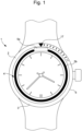
- FIG. 1 is a schematic representation of a watch 1 comprising a case 2 having a caseband 6 and a hollow bezel 3 provided with a near-field communication device 4 of the NFC type (acronym for “Near Field Communication”).
- a near-field communication device 4 can participate in carrying out a contactless electronic payment.
- such a device 4 is then a contactless electronic payment device.
- This near-field communication device 4 comprises at least one microcircuit 5a which may be an integrated circuit and an antenna 5b preferably of circular shape which may be wound in material electrically conductive, such as copper or made on a printed circuit board (or PCB) and which is connected to said microcircuit 5a.
- a microcircuit 5a which may be an integrated circuit and an antenna 5b preferably of circular shape which may be wound in material electrically conductive, such as copper or made on a printed circuit board (or PCB) and which is connected to said microcircuit 5a.
- the watch 1 comprises a bezel 3 which can be easily disassembled/disassembled in particular to change the near-field communication device 4 which would be defective and this, without damaging this bezel 3 and by extension the case 2 of watch 1.
- this bezel 3 also participates in allowing such a device 4 to be integrated into this watch 1 in a simpler and more economical manner. It will be noted that such a bezel 3 can be unidirectional or bidirectional or even a non-rotating bezel.
- This watch 1 can be a wristwatch or a mechanical watch or even a connected watch.
- This watch 1 can be waterproof and in this configuration it can be a sports watch such as a diving watch.
- the case 2 firstly comprises a caseband 6.
- the caseband 6 may be made of metal (e.g. steel, preferably stainless steel), or of a synthetic material (e.g. a composite material comprising a polymer matrix loaded with fibres, typically carbon) or of a dielectric, ceramic and/or electrically non-conductive material.
- the middle 6 has a circular outline.
- the middle 6 defines an interior space configured to accommodate a watch movement.
- This middle 6 includes horns on which a bracelet is intended to be attached for wearing the watch 1 on the wrist. If we ignore the horns, the middle 6 has a general symmetry of revolution around a central axis X.
- This watch case 2 of watch 1 comprises secondly, the bezel 3 which is removably mounted on the caseband 6.
- This bezel 3 is in fact mounted on this caseband 6 from at least one fixing element removable, in particular of the clipping or nesting type.
- a fixing element makes it possible to assemble and disassemble the bezel 3 from the caseband 6 easily, quickly and simply without damaging them in order to ensure, for example, the maintenance of the near-field communication device 4.
- this bezel 3 has an essentially annular shape. It comprises two covering elements 7a, 7b, a reversible fixing device 8 and a removable support element 11 of the near-field communication device 4. More precisely, this bezel 3 is formed by assembling the first covering element 7a with the second covering element 7b so as to define a housing in which the near-field communication device 4 is arranged. In particular, it will be noted that in this configuration the support element 11 is sandwiched between these two covering elements 7a, 7b.
- the reversible fixing device 8 comprises a fixing zone 9b and a connecting zone 9c as well as a clamping element 9a that we will describe later. It should be recalled that such a device 8 participates in the assembly of the first and second covering elements 7a, 7b by a clamping fit.
- the first covering element 7a comprises an external face 15 on which a graduation 16 is affixed or formed.
- the graduation comprises indexes, some of which are figurative and are in the form of numerals (preferably Arabic).
- One of the indexes, called the zero index 17 is in the form of a triangle pointing towards the inside of this first covering element 7a, to form an origin mark from which the user measures, in minutes, the time elapsed from a predetermined initial instant corresponding to a precise angular position of the bezel 3 relative to the caseband 6.
- This first covering element 7a also comprises an internal face 18, an internal peripheral wall 19 and an external peripheral wall.
- This first covering element 7a comprises an arrangement zone 20 for said at least one microcircuit 5a of the communication device 4 which is provided both in a part of the internal peripheral wall 19 and a part of the internal face 18.
- This arrangement zone 20 is preferably located behind the zero index 17.
- the first covering element 7a also comprises the reversible fixing zone 9b comprising a groove 10 defined on its external peripheral wall. Such a groove 10 is specifically configured to receive the clamping element 9a.
- This clamping element 9a may be a compressible seal that is smaller than the circumference (circumference) of the groove 10. Such a clamping element 9a is therefore arranged in the groove 10 by being stretched. Despite its smaller circumference, the clamping element 9a finds its place in this groove 10 thanks to its elastic properties, which allow it to be relaxed and which once placed in the groove 10 will shrink to press against the external peripheral wall in the groove 10.
- This reversible fixing zone 9b is able to cooperate with the reversible connecting zone 9c defined on an internal peripheral wall 21 of the second covering element 7b of the bezel 3.
- This connecting zone 9c is able to cooperate with an external surface 20 of the clamping element 9a mounted in the groove 10 of the fixing zone 9b in order to reversibly connect the first covering element 7a with the second covering element 7b. It will be noted that the connecting zone 9c is able to cooperate by friction with the external surface 20 of the clamping element 9a arranged in the groove 10.
- the diameter connecting two points of the external surface 20 of the clamping element 9a mounted on the first covering element 7a is substantially greater or strictly greater than the diameter connecting two points of the connection zone 9c of the second covering element 7b. It will be noted that the diameter connecting two points of the groove 10 of the first covering element 7a is substantially less or strictly less than the diameter connecting two points of the connection zone 9c of the second covering element 7b. Furthermore, it is understood that the diameter of the first covering element 7a without the clamping element 9a is substantially less or strictly less than that of the second covering element 7b.
- the second covering element 7b comprises an inner face which is contiguous to its inner peripheral wall 21.
- This inner face is in particular configured to be a support face of the support element 11 of the bezel 3 when the first and second covering elements 7a, 7b are assembled.
- This second covering element 7b comprises an outer face 22 opposite the inner face and which extends opposite the middle part 6, and more precisely opposite a portion of the middle part 6 provided for the removable attachment of the bezel 3.
- This outer face 22 comprises a toothed crown 23 of this bezel 3 which is used for the angular indexing of the bezel 3 relative to the middle part 6.
- This toothed crown 23 comprises a peripheral series of teeth, each tooth of which is asymmetrical and comprises an inclined ramp and a vertical stop surface, possibly connected by a horizontal plate.
- This second covering element 7b is also provided with an external peripheral wall on which a gripping zone 24 of the bezel 3 is defined.
- the bezel 3 comprises the removable support element 11 of the near-field communication device 4. More specifically, this support element 11 is provided with an upper face 13a comprising a reception area 12b of the antenna 5b of said communication device 4. This reception area 12b on which said antenna 5b is arranged is in particular included in an inclined plane.
- This support element 11 also comprises a recess 12a, or a through opening, in which said at least one microcircuit 5a may be arranged in whole or in part.
- the receiving area 12b may comprise/form a protective magnetic screen such as ferrite by being covered with a layer of ferrite-based material.
- a protective magnetic screen such as ferrite by being covered with a layer of ferrite-based material.
- the portion of the inner peripheral wall and the inner face of the second covering element 7b located near said at least one microcircuit 5a may also comprise such a layer of material in order to form a magnetic screen with this support element 11.
- this support element 11 comprises a lower face 13b comprising a plurality of feet 14 capable of bearing on the internal face of the second covering element 7b of this bezel 3 when this second covering element 7b is assembled to the first covering element 7a.
- the first and second covering elements 7a, 7b, the clamping element 9a and the support element 11 are adapted to the operation of the near-field communication device 4 by being manufactured from dielectric and electrically non-conductive materials, such as for example plastic, ceramic, or any other synthetic material.
- the communication device 4 comprises a coating of waterproof material which makes it impermeable to water and moisture.
- This coating of material is also capable of making it resistant to high pressures which may be encountered during dives carried out by the wearer of the watch 1.
- This coating of material may comprise organic or inorganic layers or a combination of these two types of layers.
Landscapes
- Physics & Mathematics (AREA)
- General Physics & Mathematics (AREA)
- Engineering & Computer Science (AREA)
- Computer Networks & Wireless Communication (AREA)
- Business, Economics & Management (AREA)
- Signal Processing (AREA)
- Accounting & Taxation (AREA)
- Strategic Management (AREA)
- General Business, Economics & Management (AREA)
- Theoretical Computer Science (AREA)
- Electric Clocks (AREA)
- Structure Of Receivers (AREA)
Description
L'invention concerne une boîte de montre comprenant un dispositif de communication en champ proche, ainsi qu'une montre équipée d'une telle boîte.The invention relates to a watch case comprising a near-field communication device, as well as a watch equipped with such a case.
On connait dans l'état de la technique, des objets portables de paiement sans contact tels que des montres qui sont aptes à participer à la réalisation d'un paiement électronique. De telles montres comportent classiquement des moyens de communication en champ proche composés d'une puce électronique, ou circuit intégré, reliée électriquement à une antenne. La plupart du temps, ces moyens n'ont pas besoin d'une alimentation électrique autonome et sont destinés à communiquer automatiquement avec un lecteur dès qu'ils s'en approchent. Le champ électromagnétique du lecteur génère un courant induit dans l'antenne qui alimente la puce et lui permet d'émettre à son tour un signal via l'antenne.In the state of the art, we know of contactless payment portable objects such as watches that are capable of participating in the making of an electronic payment. Such watches typically include near-field communication means composed of an electronic chip, or integrated circuit, electrically connected to an antenna. Most of the time, these means do not require an autonomous power supply and are intended to communicate automatically with a reader as soon as they approach it. The electromagnetic field of the reader generates an induced current in the antenna that powers the chip and allows it to in turn emit a signal via the antenna.
Toutefois ces moyens de communication en champ proche ont une durée de vie limitée par l'espérance de vie du circuit intégré plus particulièrement de celle de sa partie "coffre-fort électronique" qui ne doit pas excéder dix ans. En effet, passé cette durée ces moyens de communication ne permettent plus la réalisation de paiement électronique et doivent donc être remplacés. Au regard de l'agencement particulier de ces moyens de communication dans ces montres de l'état de la technique, les opérations de maintenance devant conduire à de tels remplacements sont souvent complexes voire impossibles et aussi coûteuses car elles peuvent notamment nécessiter le remplacement d'autres pièces de la montre qui sont associées à ces moyens de communication.However, these near-field communication means have a lifespan limited by the life expectancy of the integrated circuit, more particularly that of its "electronic safe" part, which must not exceed ten years. Indeed, after this duration, these communication means no longer allow electronic payment to be made and must therefore be replaced. In view of the particular arrangement of these communication means in these state-of-the-art watches, the maintenance operations that must lead to such replacements are often complex or even impossible and also costly because they may in particular require the replacement of other parts of the watch that are associated with these communication means.
L'état de l'art n'offre pas de solution permettant de surmonter de tels inconvénients, il existe par conséquent un besoin de proposer une alternative aux solutions existantes.The state of the art does not offer a solution to overcome such drawbacks, therefore there is a need to propose an alternative to existing solutions.
Les documents
La présente invention a pour but de pallier les inconvénients de l'art antérieur en proposant de fournir une montre dont la boite comprend une lunette qui peut être facilement et rapidement démontée pour assurer la maintenance du dispositif de communication en champ proche qu'elle contient sans impacter l'intégrité ni l'étanchéité du produit.The present invention aims to overcome the drawbacks of the prior art by proposing to provide a watch whose case includes a bezel which can be easily and quickly dismantled to ensure maintenance of the near-field communication device which it contains without impacting the integrity or the sealing of the product.
Dans ce dessein, un aspect de l'invention concerne une boite de montre telle que définie dans la revendication indépendante 1 annexée. Des réalisations préférées de cette boite sont définies dans les revendications dépendantes 2 à 12.In this regard, one aspect of the invention relates to a watch case as defined in the appended independent claim 1. Preferred embodiments of this case are defined in
Dans un autre aspect, l'invention concerne une montre comportant une telle boite comprenant un dispositif de communication en champ proche.In another aspect, the invention relates to a watch comprising such a case comprising a near field communication device.
Avantageusement, la montre est étanche.Advantageously, the watch is waterproof.
Les buts, avantages et caractéristiques...
- la
figure 1 est une représentation schématique d'une montre pourvue d'une boite comprenant une lunette dans laquelle est agencé un dispositif de communication en champ proche, selon un mode de réalisation de l'invention ; - la
figure 2 est une vue de dessus d'une représentation en perspective de la lunette, selon le mode de réalisation de l'invention ; - la
figure 3 est une vue de dessous d'une représentation en perspective de la lunette, selon le mode de réalisation de l'invention, et - la
figure 4 est une vue éclatée d'une représentation en perspective de la lunette, selon le mode de réalisation de l'invention.
- there
figure 1 is a schematic representation of a watch provided with a case comprising a bezel in which a near-field communication device is arranged, according to one embodiment of the invention; - there
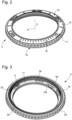
figure 2 is a top view of a perspective representation of the telescope, according to the embodiment of the invention; - there
figure 3 is a bottom view of a perspective representation of the telescope, according to the embodiment of the invention, and - there
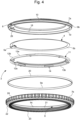
figure 4 is an exploded view of a perspective representation of the telescope, according to the embodiment of the invention.
La
Ce dispositif de communication 4 en champ proche comprend au moins un microcircuit 5a qui peut être un circuit intégré et une antenne 5b de préférence de forme circulaire pouvant être bobinée en matériau électriquement conducteur, comme par exemple du cuivre ou réalisée sur un circuit imprimé (ou PCB de l'anglais « Printed Circuit Board ») et qui est reliée audit microcircuit 5a.This near-
Dans cette configuration, la montre 1 selon l'invention comprend une lunette 3 qui peut être facilement démontée/désassemblée notamment pour changer le dispositif de communication 4 en champ proche qui serait défectueux et ce, sans endommager cette lunette 3 et par extension la boite 2 de montre 1. De plus, cette lunette 3 participe aussi à permettre d'intégrer un tel dispositif 4 dans cette montre 1 de manière plus simple et plus économique. On notera qu'une telle lunette 3 peut être unidirectionnelle ou bidirectionnelle ou encore une lunette non tournante.In this configuration, the watch 1 according to the invention comprises a
Cette montre 1 peut être une montre bracelet ou une montre mécanique ou encore une montre connectée. Cette montre 1 peut être étanche et dans cette configuration elle peut être une montre sportive telle qu'une montre de plongée.This watch 1 can be a wristwatch or a mechanical watch or even a connected watch. This watch 1 can be waterproof and in this configuration it can be a sports watch such as a diving watch.
Dans cette montre 1, la boite 2 comprend en premier lieu, une carrure 6. La carrure 6 peut être réalisée en métal (par ex. en acier, de préférence inoxydable), ou dans un matériau synthétique (par ex. dans un matériau composite comprenant une matrice polymère chargée de fibres, typiquement de carbone) ou encore dans un matériau diélectrique, céramique et/ou électriquement non conducteur. Comme on le voit sur la
Cette boite 2 de montre 1 comprend en deuxième lieu, la lunette 3 qui est montée de manière amovible sur la carrure 6. Cette lunette 3 est en effet montée sur cette carrure 6 à partir d'au moins un élément de fixation amovible notamment de type clippage ou encore emboitage. Un tel élément de fixation permet d'assembler et désassembler la lunette 3 de la carrure 6 facilement, rapidement et simplement sans les endommager afin d'assurer par exemple la maintenance du dispositif de communication 4 en champ proche.This
Sur les
Le premier élément d'habillage 7a comprend une face externe 15 sur laquelle est apposée ou formée une graduation 16. Dans l'exemple illustré, la graduation comprend des index dont certains sont figuratifs et se présentent sous forme de chiffres (de préférence arabes). L'un des index, dit index de zéro 17, se présente sous forme d'un triangle pointant vers l'intérieur de ce premier élément d'habillage 7a, pour former un repère d'origine à partir duquel l'utilisateur mesure, en minutes, le temps écoulé à partir d'un instant initial prédéterminé correspondant à une position angulaire précise de la lunette 3 par rapport à la carrure 6. Ce premier élément d'habillage 7a comprend aussi un face interne 18, une paroi périphérique interne 19 et une paroi périphérique externe.The first covering
Ce premier élément d'habillage 7a comprend une zone d'agencement 20 dudit au moins un microcircuit 5a du dispositif de communication 4 qui est ménagée à la fois dans une partie de la paroi périphérique interne 19 et une partie de la face interne 18. Cette zone d'agencement 20 est de préférence localisée derrière l'index de zéro 17.This first covering
Le premier élément d'habillage 7a comprend également la zone de fixation 9b réversible comprenant une rainure 10 définie sur sa paroi périphérique externe. Une telle rainure 10 est spécifiquement configurée pour recevoir l'élément de serrage 9a.The first covering
Cet élément de serrage 9a peut être un joint comprimable qui est de plus petite taille que le pourtour (circonférence) de la rainure 10. Un tel élément de serrage 9a est donc agencé dans la rainure 10 en étant étiré. Malgré sa plus petite circonférence, l'élément de serrage 9a trouve sa place dans cette rainure 10 grâce à ses propriétés élastiques, qui lui permettent d'être détendu et qui une fois placé dans la rainure 10 se rétrécira pour se plaquer contre la paroi périphérique externe dans la rainure 10.This
Cette zone de fixation 9b réversible est apte à coopérer avec la zone de liaison 9c réversible définie sur une paroi périphérique interne 21 du deuxième élément d'habillage 7b de la lunette 3. Cette zone de liaison 9c est apte à coopérer avec une surface externe 20 de l'élément de serrage 9a monté dans la rainure 10 de la zone de fixation 9b afin de relier de manière réversible le premier élément d'habillage 7a avec le deuxième élément d'habillage 7b. On notera que la zone de liaison 9c est susceptible de coopérer par frottement avec la surface externe 20 de l'élément de serrage 9a agencé dans la rainure 10.This
Dans cette configuration, le diamètre reliant deux points de la surface externe 20 de l'élément de serrage 9a monté sur le premier élément d'habillage 7a est sensiblement supérieur ou strictement supérieur au diamètre reliant deux points de la zone de liaison 9c du deuxième élément d'habillage 7b. On notera que le diamètre reliant deux points de la rainure 10 du premier élément d'habillage 7a est sensiblement inférieur ou strictement inférieur au diamètre reliant deux points de la zone de liaison 9c du deuxième élément d'habillage 7b. En outre, on comprend que le diamètre du premier élément d'habillage 7a dépourvu de l'élément de serrage 9a, est sensiblement inférieur ou strictement inférieur à celui du deuxième élément d'habillage 7b.In this configuration, the diameter connecting two points of the
Le deuxième élément d'habillage 7b comprend une face interne qui est contiguë à sa paroi périphérique interne 21. Cette face interne est notamment configurée pour être une face d'appui de l'élément de support 11 de la lunette 3 lorsque les premier et deuxième éléments d'habillage 7a, 7b sont assemblés. Ce deuxième élément d'habillage 7b comporte une face externe 22 opposée à la face interne et qui s'étend en regard de la carrure 6, et plus précisément en regard d'une partie de la carrure 6 prévue pour la fixation amovible de la lunette 3. Cette face externe 22 comprend une couronne dentée 23 de cette lunette 3 qui sert à l'indexage angulaire de la lunette 3 par rapport à la carrure 6. Cette couronne dentée 23 comprend une série périphérique de dents dont chaque dent est asymétrique et comprend une rampe inclinée et une surface d'arrêt verticale, éventuellement reliées par un plateau horizontal.The
Ce deuxième élément d'habillage 7b est aussi pourvu d'une paroi périphérique externe sur laquelle est définie une zone de préhension 24 de la lunette 3.This
Ainsi que nous l'avons évoqué, la lunette 3 comprend l'élément de support 11 amovible du dispositif de communication 4 en champ proche. Plus précisément, cet élément de support 11 est pourvu d'une face supérieure 13a comportant une zone de réception 12b de l'antenne 5b dudit dispositif de communication 4. Cette zone de réception 12b sur laquelle est agencée ladite antenne 5b est notamment comprise dans un plan incliné. Cet élément de support 11 comprend aussi un évidement 12a, ou une ouverture traversante, dans lequel est susceptible d'être agencé en tout ou partie ledit au moins un microcircuit 5a.As mentioned, the
Dans une variante, la zone de réception 12b peut comprendre/former un écran magnétique de protection comme la ferrite en étant couverte d'une couche de matériau à base de la ferrite. Dans ce contexte, la partie de la paroi périphérique interne et la face interne du deuxième élément d'habillage 7b localisées à proximité dudit au moins un microcircuit 5a, peuvent également comprendre une telle couche de matériau afin de former un écran magnétique avec cet élément de support 11.In a variant, the receiving
En outre cet élément de support 11 comprend une face inférieure 13b comprenant une pluralité de pieds 14 susceptibles de prendre appui sur la face interne du deuxième élément d'habillage 7b de cette lunette 3 lorsque ce deuxième élément d'habillage 7b est assemblé au premier élément d'habillage 7a.Furthermore, this
Dans cette lunette 3, les premier et deuxième éléments d'habillage 7a, 7b, l'élément de serrage 9a et l'élément de support 11 sont adaptés au fonctionnement du dispositif de communication 4 en champ proche en étant fabriqués en des matériaux diélectriques et électriquement non conducteurs, comme par exemple le plastique, la céramique, ou tout autre matériau de synthèse.In this
Par ailleurs, le dispositif de communication 4 comprend un enrobage de matière étanche qui le rend imperméable à l'eau et à l'humidité. Cet enrobage de matière est aussi apte à le rendre résistant à des pressions élevées pouvant être rencontrées lors de plongées effectuées par le porteur de la montre 1. Cet enrobage de matière peut comprendre des couches organiques ou inorganiques ou une combinaison de ces deux types de couches.Furthermore, the
On comprendra que diverses modifications et/ou améliorations et/ou combinaisons évidentes pour l'homme du métier peuvent être apportées aux différents modes de réalisation de l'invention exposée cidessus sans sortir du cadre de l'invention définie par les revendications annexées.It will be understood that various modifications and/or improvements and/or combinations obvious to those skilled in the art can be made to the different embodiments of the invention set out above. without departing from the scope of the invention defined by the appended claims.
Claims (14)
- A watch (1) case (2) including a middle (6) and a hollow bezel (3) provided with a near-field communication device (4) comprising at least one microcircuit (5a) connected to an antenna (5b), said bezel (3) being removably mounted on said middle (6) and formed by an assembly of two lining elements (7a, 7b) that could define a housing within which said near-field communication device (4) is arranged, said first and second lining elements (7a, 7b) of the bezel (3) being assembled together by means of a reversible fastening device (8), characterised in that the first lining element (7a) comprises a reversible fastening area (9b) comprising a groove (10) defined on an outer peripheral wall of the first lining element (7a), said groove (10) being configured so as to receive a tightening element (9a) of said reversible fastening device (8).
- The case (2) according to the preceding claim, characterised in that the tightening element (9a) is a compressible seal.
- The case (2) according to any one of the preceding claims, characterised in that said second lining element (7b) comprises a reversible connecting area (9c) that could cooperate by friction with a tightening element (9a) arranged in a groove (10) comprised within the first lining element (7a).
- The case (2) according to any one of the preceding claims, characterised in that the bezel (3) comprises a removable support element (11) of the near-field communication device (4).
- The case (2) according to the preceding claim, characterised in that the support element (11) comprises over its upper face (13a) a reception area (12b) in particular in an inclined plane that could receive said antenna (5b).
- The case (2) according to the preceding claim, characterised in that the reception area (12b) of the support element (11) comprises or is formed by a protective magnetic screen such as ferrite.
- The case (2) according to any one of claims 4 to 6, characterised in that the support element (11) comprises a recess (12a) within which said at least one microcircuit (5a) could be completely or partially arranged.
- The case (2) according to any one of claims 4 to 7, characterised in that the support element (11) comprises over its lower face (13b) at least two feet (14) that could bear on an inner face (15) of the second lining element (7b) of the bezel (3) when this second lining element (7b) is assembled to the first lining element (7a).
- The case (2) according to the preceding claim, characterised in that the first and second lining elements (7a, 7b), the removable support element (11) and the tightening element (9a) are made of at least one dielectric and/or electrically non-conductive material.
- The case (2) according to any one of the preceding claims, characterised in that said bezel (3) is fastened on the middle (6) by means of at least one removable fastening element in particular a clipping-type one.
- The case (2) according to any one of the preceding claims, characterised in that, the near-field communication device (4) comprises a sealing material coating that could make said device (4) waterproof and/or moistureproof.
- The case (2) according to any one of the preceding claims, characterised in that the near-field communication device (4) is a contactless electronic payment device.
- A watch (1) including a case (2) comprising a near-field communication device (4), according to claims 1 to 12.
- The watch (1) according to the preceding claim, characterised in that it is water-resistant.
Priority Applications (4)
| Application Number | Priority Date | Filing Date | Title |
|---|---|---|---|
| EP20210655.5A EP4006654B1 (en) | 2020-11-30 | 2020-11-30 | Watch case comprising a near field communication device |
| US17/495,145 US12353174B2 (en) | 2020-11-30 | 2021-10-06 | Watch case comprising a near-field communication device |
| JP2021170700A JP7181369B2 (en) | 2020-11-30 | 2021-10-19 | Portable watch case with near field communication device |
| CN202111441111.2A CN114578674B (en) | 2020-11-30 | 2021-11-30 | Watch case including a near field communication device |
Applications Claiming Priority (1)
| Application Number | Priority Date | Filing Date | Title |
|---|---|---|---|
| EP20210655.5A EP4006654B1 (en) | 2020-11-30 | 2020-11-30 | Watch case comprising a near field communication device |
Publications (2)
| Publication Number | Publication Date |
|---|---|
| EP4006654A1 EP4006654A1 (en) | 2022-06-01 |
| EP4006654B1 true EP4006654B1 (en) | 2025-01-01 |
Family
ID=73646193
Family Applications (1)
| Application Number | Title | Priority Date | Filing Date |
|---|---|---|---|
| EP20210655.5A Active EP4006654B1 (en) | 2020-11-30 | 2020-11-30 | Watch case comprising a near field communication device |
Country Status (4)
| Country | Link |
|---|---|
| US (1) | US12353174B2 (en) |
| EP (1) | EP4006654B1 (en) |
| JP (1) | JP7181369B2 (en) |
| CN (1) | CN114578674B (en) |
Families Citing this family (1)
| Publication number | Priority date | Publication date | Assignee | Title |
|---|---|---|---|---|
| USD1119626S1 (en) * | 2024-04-02 | 2026-03-24 | Tudor Watch U.S.A., Llc | Watch dial |
Family Cites Families (19)
| Publication number | Priority date | Publication date | Assignee | Title |
|---|---|---|---|---|
| JPS5241898Y2 (en) * | 1972-12-08 | 1977-09-22 | ||
| EP0844685B1 (en) * | 1996-11-22 | 2003-03-05 | Eta SA Fabriques d'Ebauches | Timepiece provided with an antenna for receiving and/or transmitting radio signals |
| CH690525A5 (en) | 1996-11-22 | 2000-09-29 | Ebauchesfabrik Eta Ag | Timepiece including a receiving antenna and / or transmitting a radio broadcast signal. |
| JP2004294110A (en) * | 2003-03-25 | 2004-10-21 | Matsushita Electric Works Ltd | Offset voltage correction device |
| KR200406111Y1 (en) | 2005-11-01 | 2006-01-20 | 김재섭 | Traffic card combined watch |
| DE602006016553D1 (en) | 2006-03-30 | 2010-10-14 | Richemont Int Sa | Reversible clock |
| FR2988886A1 (en) * | 2012-03-30 | 2013-10-04 | France Telecom | HULL FOR MOBILE TELEPHONE AND MOBILE TERMINAL |
| JP5998795B2 (en) * | 2012-09-24 | 2016-09-28 | セイコーエプソン株式会社 | Electronic clock with built-in antenna |
| US9934901B2 (en) * | 2013-09-27 | 2018-04-03 | Panasonic Intellectual Property Management Co., Ltd. | Near-field communications element and electronic device having same mounted therein |
| TWI511682B (en) * | 2013-11-04 | 2015-12-11 | Sheng Hsin Liao | Portable modularized stack device |
| KR20160052253A (en) | 2014-11-04 | 2016-05-12 | 삼성전자주식회사 | Antenna and electronic device having it |
| CH711231A2 (en) | 2015-06-19 | 2016-12-30 | Omega Sa | Watch strap. |
| EP3112958B1 (en) * | 2015-07-01 | 2022-03-16 | Bulgari Horlogerie S.A. | Timepiece comprising a near field communication device |
| EP3141969A1 (en) | 2015-09-10 | 2017-03-15 | Omega SA | Cladding element with integrated communication circuit |
| CN105361368B (en) | 2015-11-25 | 2017-11-17 | 广州合利宝支付科技有限公司 | A kind of mobile-payment system |
| EP3343450B1 (en) | 2016-12-29 | 2020-02-05 | The Swatch Group Research and Development Ltd | Portable object comprising a near-field connection device |
| CH713968B1 (en) | 2017-07-11 | 2021-05-31 | Winwatch Ip Ltd | Watch glass comprising an NFC near-field communication device and watch equipped with such a glass. |
| US10285643B2 (en) | 2017-09-11 | 2019-05-14 | Apple Inc. | Retention system for electronic devices |
| CN211630640U (en) | 2020-02-19 | 2020-10-02 | Oppo广东移动通信有限公司 | Fixed components and electronic equipment |
-
2020
- 2020-11-30 EP EP20210655.5A patent/EP4006654B1/en active Active
-
2021
- 2021-10-06 US US17/495,145 patent/US12353174B2/en active Active
- 2021-10-19 JP JP2021170700A patent/JP7181369B2/en active Active
- 2021-11-30 CN CN202111441111.2A patent/CN114578674B/en active Active
Also Published As
| Publication number | Publication date |
|---|---|
| EP4006654A1 (en) | 2022-06-01 |
| JP2022087018A (en) | 2022-06-09 |
| US12353174B2 (en) | 2025-07-08 |
| CN114578674A (en) | 2022-06-03 |
| JP7181369B2 (en) | 2022-11-30 |
| US20220171345A1 (en) | 2022-06-02 |
| CN114578674B (en) | 2025-03-28 |
Similar Documents
| Publication | Publication Date | Title |
|---|---|---|
| EP0221233B1 (en) | Watch case made of a hard material | |
| EP3182223B1 (en) | Watch strap | |
| EP0098239B1 (en) | Wrist watch with a strap hinged to the case | |
| EP1950632A1 (en) | Watch with a polygonal bezel | |
| EP1378805A1 (en) | Timepiece fitted with an antenna | |
| CH690525A5 (en) | Timepiece including a receiving antenna and / or transmitting a radio broadcast signal. | |
| EP4006654B1 (en) | Watch case comprising a near field communication device | |
| EP4145230B1 (en) | Bezel for a timepiece | |
| EP4176755A1 (en) | Assembly of a watch strap on a watch case | |
| EP4006653B1 (en) | Watch case comprising a control device for a near field communication device | |
| CH718101A2 (en) | Watch case comprising a near field communication device. | |
| CH690870A5 (en) | Gold watch for deep diving, comprises support for watch glass and bottom which are strengthened against external pressure by a tank made from steel or titanium which houses the mechanism | |
| EP0844685B1 (en) | Timepiece provided with an antenna for receiving and/or transmitting radio signals | |
| EP3712714B1 (en) | Dial for a universal watch | |
| WO2004090648A1 (en) | Watch with movable decorative elements | |
| CH708959B1 (en) | Watch case comprising a rotating bezel. | |
| CH718100A2 (en) | Watch case comprising a device for controlling a near-field communication device. | |
| EP3974914B1 (en) | Device for locking a movement of a clock piece | |
| EP1544696B1 (en) | Portable electronic device comprising a pressure sensor | |
| EP0269872A1 (en) | Watch case | |
| CH721182A2 (en) | Glasses including a near-field communication device | |
| CH257783A (en) | Watch. | |
| EP1975748B1 (en) | Wrist-watch case | |
| EP1980921B1 (en) | Timepiece with a turning bezel | |
| CH715720A2 (en) | Adjustable back for a timepiece. |
Legal Events
| Date | Code | Title | Description |
|---|---|---|---|
| PUAI | Public reference made under article 153(3) epc to a published international application that has entered the european phase |
Free format text: ORIGINAL CODE: 0009012 |
|
| STAA | Information on the status of an ep patent application or granted ep patent |
Free format text: STATUS: THE APPLICATION HAS BEEN PUBLISHED |
|
| AK | Designated contracting states |
Kind code of ref document: A1 Designated state(s): AL AT BE BG CH CY CZ DE DK EE ES FI FR GB GR HR HU IE IS IT LI LT LU LV MC MK MT NL NO PL PT RO RS SE SI SK SM TR |
|
| STAA | Information on the status of an ep patent application or granted ep patent |
Free format text: STATUS: REQUEST FOR EXAMINATION WAS MADE |
|
| 17P | Request for examination filed |
Effective date: 20221201 |
|
| RBV | Designated contracting states (corrected) |
Designated state(s): AL AT BE BG CH CY CZ DE DK EE ES FI FR GB GR HR HU IE IS IT LI LT LU LV MC MK MT NL NO PL PT RO RS SE SI SK SM TR |
|
| P01 | Opt-out of the competence of the unified patent court (upc) registered |
Effective date: 20230615 |
|
| GRAP | Despatch of communication of intention to grant a patent |
Free format text: ORIGINAL CODE: EPIDOSNIGR1 |
|
| STAA | Information on the status of an ep patent application or granted ep patent |
Free format text: STATUS: GRANT OF PATENT IS INTENDED |
|
| RIC1 | Information provided on ipc code assigned before grant |
Ipc: G04B 47/04 20060101ALI20240718BHEP Ipc: G04B 47/00 20060101ALI20240718BHEP Ipc: G04B 19/28 20060101ALI20240718BHEP Ipc: G04R 20/28 20130101ALI20240718BHEP Ipc: G04R 60/08 20130101AFI20240718BHEP |
|
| INTG | Intention to grant announced |
Effective date: 20240802 |
|
| GRAS | Grant fee paid |
Free format text: ORIGINAL CODE: EPIDOSNIGR3 |
|
| GRAA | (expected) grant |
Free format text: ORIGINAL CODE: 0009210 |
|
| STAA | Information on the status of an ep patent application or granted ep patent |
Free format text: STATUS: THE PATENT HAS BEEN GRANTED |
|
| AK | Designated contracting states |
Kind code of ref document: B1 Designated state(s): AL AT BE BG CH CY CZ DE DK EE ES FI FR GB GR HR HU IE IS IT LI LT LU LV MC MK MT NL NO PL PT RO RS SE SI SK SM TR |
|
| REG | Reference to a national code |
Ref country code: GB Ref legal event code: FG4D Free format text: NOT ENGLISH |
|
| REG | Reference to a national code |
Ref country code: DE Ref legal event code: R096 Ref document number: 602020043987 Country of ref document: DE |
|
| REG | Reference to a national code |
Ref country code: CH Ref legal event code: EP |
|
| REG | Reference to a national code |
Ref country code: IE Ref legal event code: FG4D Free format text: LANGUAGE OF EP DOCUMENT: FRENCH |
|
| REG | Reference to a national code |
Ref country code: LT Ref legal event code: MG9D |
|
| REG | Reference to a national code |
Ref country code: NL Ref legal event code: MP Effective date: 20250101 |
|
| REG | Reference to a national code |
Ref country code: AT Ref legal event code: MK05 Ref document number: 1756877 Country of ref document: AT Kind code of ref document: T Effective date: 20250101 |
|
| PG25 | Lapsed in a contracting state [announced via postgrant information from national office to epo] |
Ref country code: NL Free format text: LAPSE BECAUSE OF FAILURE TO SUBMIT A TRANSLATION OF THE DESCRIPTION OR TO PAY THE FEE WITHIN THE PRESCRIBED TIME-LIMIT Effective date: 20250101 |
|
| PG25 | Lapsed in a contracting state [announced via postgrant information from national office to epo] |
Ref country code: FI Free format text: LAPSE BECAUSE OF FAILURE TO SUBMIT A TRANSLATION OF THE DESCRIPTION OR TO PAY THE FEE WITHIN THE PRESCRIBED TIME-LIMIT Effective date: 20250101 |
|
| PG25 | Lapsed in a contracting state [announced via postgrant information from national office to epo] |
Ref country code: PL Free format text: LAPSE BECAUSE OF FAILURE TO SUBMIT A TRANSLATION OF THE DESCRIPTION OR TO PAY THE FEE WITHIN THE PRESCRIBED TIME-LIMIT Effective date: 20250101 |
|
| PG25 | Lapsed in a contracting state [announced via postgrant information from national office to epo] |
Ref country code: ES Free format text: LAPSE BECAUSE OF FAILURE TO SUBMIT A TRANSLATION OF THE DESCRIPTION OR TO PAY THE FEE WITHIN THE PRESCRIBED TIME-LIMIT Effective date: 20250101 |
|
| PG25 | Lapsed in a contracting state [announced via postgrant information from national office to epo] |
Ref country code: IS Free format text: LAPSE BECAUSE OF FAILURE TO SUBMIT A TRANSLATION OF THE DESCRIPTION OR TO PAY THE FEE WITHIN THE PRESCRIBED TIME-LIMIT Effective date: 20250501 Ref country code: NO Free format text: LAPSE BECAUSE OF FAILURE TO SUBMIT A TRANSLATION OF THE DESCRIPTION OR TO PAY THE FEE WITHIN THE PRESCRIBED TIME-LIMIT Effective date: 20250401 |
|
| PG25 | Lapsed in a contracting state [announced via postgrant information from national office to epo] |
Ref country code: HR Free format text: LAPSE BECAUSE OF FAILURE TO SUBMIT A TRANSLATION OF THE DESCRIPTION OR TO PAY THE FEE WITHIN THE PRESCRIBED TIME-LIMIT Effective date: 20250101 |
|
| PG25 | Lapsed in a contracting state [announced via postgrant information from national office to epo] |
Ref country code: LV Free format text: LAPSE BECAUSE OF FAILURE TO SUBMIT A TRANSLATION OF THE DESCRIPTION OR TO PAY THE FEE WITHIN THE PRESCRIBED TIME-LIMIT Effective date: 20250101 Ref country code: PT Free format text: LAPSE BECAUSE OF FAILURE TO SUBMIT A TRANSLATION OF THE DESCRIPTION OR TO PAY THE FEE WITHIN THE PRESCRIBED TIME-LIMIT Effective date: 20250502 |
|
| PG25 | Lapsed in a contracting state [announced via postgrant information from national office to epo] |
Ref country code: GR Free format text: LAPSE BECAUSE OF FAILURE TO SUBMIT A TRANSLATION OF THE DESCRIPTION OR TO PAY THE FEE WITHIN THE PRESCRIBED TIME-LIMIT Effective date: 20250402 Ref country code: BG Free format text: LAPSE BECAUSE OF FAILURE TO SUBMIT A TRANSLATION OF THE DESCRIPTION OR TO PAY THE FEE WITHIN THE PRESCRIBED TIME-LIMIT Effective date: 20250101 |
|
| PG25 | Lapsed in a contracting state [announced via postgrant information from national office to epo] |
Ref country code: AT Free format text: LAPSE BECAUSE OF FAILURE TO SUBMIT A TRANSLATION OF THE DESCRIPTION OR TO PAY THE FEE WITHIN THE PRESCRIBED TIME-LIMIT Effective date: 20250101 |
|
| PG25 | Lapsed in a contracting state [announced via postgrant information from national office to epo] |
Ref country code: CZ Free format text: LAPSE BECAUSE OF FAILURE TO SUBMIT A TRANSLATION OF THE DESCRIPTION OR TO PAY THE FEE WITHIN THE PRESCRIBED TIME-LIMIT Effective date: 20250101 |
|
| PG25 | Lapsed in a contracting state [announced via postgrant information from national office to epo] |
Ref country code: SE Free format text: LAPSE BECAUSE OF FAILURE TO SUBMIT A TRANSLATION OF THE DESCRIPTION OR TO PAY THE FEE WITHIN THE PRESCRIBED TIME-LIMIT Effective date: 20250101 |
|
| REG | Reference to a national code |
Ref country code: DE Ref legal event code: R097 Ref document number: 602020043987 Country of ref document: DE |
|
| PG25 | Lapsed in a contracting state [announced via postgrant information from national office to epo] |
Ref country code: SM Free format text: LAPSE BECAUSE OF FAILURE TO SUBMIT A TRANSLATION OF THE DESCRIPTION OR TO PAY THE FEE WITHIN THE PRESCRIBED TIME-LIMIT Effective date: 20250101 |
|
| PG25 | Lapsed in a contracting state [announced via postgrant information from national office to epo] |
Ref country code: DK Free format text: LAPSE BECAUSE OF FAILURE TO SUBMIT A TRANSLATION OF THE DESCRIPTION OR TO PAY THE FEE WITHIN THE PRESCRIBED TIME-LIMIT Effective date: 20250101 |
|
| PG25 | Lapsed in a contracting state [announced via postgrant information from national office to epo] |
Ref country code: IT Free format text: LAPSE BECAUSE OF FAILURE TO SUBMIT A TRANSLATION OF THE DESCRIPTION OR TO PAY THE FEE WITHIN THE PRESCRIBED TIME-LIMIT Effective date: 20250101 |
|
| PG25 | Lapsed in a contracting state [announced via postgrant information from national office to epo] |
Ref country code: EE Free format text: LAPSE BECAUSE OF FAILURE TO SUBMIT A TRANSLATION OF THE DESCRIPTION OR TO PAY THE FEE WITHIN THE PRESCRIBED TIME-LIMIT Effective date: 20250101 |
|
| PG25 | Lapsed in a contracting state [announced via postgrant information from national office to epo] |
Ref country code: RO Free format text: LAPSE BECAUSE OF FAILURE TO SUBMIT A TRANSLATION OF THE DESCRIPTION OR TO PAY THE FEE WITHIN THE PRESCRIBED TIME-LIMIT Effective date: 20250101 |
|
| PG25 | Lapsed in a contracting state [announced via postgrant information from national office to epo] |
Ref country code: SK Free format text: LAPSE BECAUSE OF FAILURE TO SUBMIT A TRANSLATION OF THE DESCRIPTION OR TO PAY THE FEE WITHIN THE PRESCRIBED TIME-LIMIT Effective date: 20250101 |
|
| PLBE | No opposition filed within time limit |
Free format text: ORIGINAL CODE: 0009261 |
|
| STAA | Information on the status of an ep patent application or granted ep patent |
Free format text: STATUS: NO OPPOSITION FILED WITHIN TIME LIMIT |
|
| REG | Reference to a national code |
Ref country code: CH Ref legal event code: L10 Free format text: ST27 STATUS EVENT CODE: U-0-0-L10-L00 (AS PROVIDED BY THE NATIONAL OFFICE) Effective date: 20251112 |
|
| REG | Reference to a national code |
Ref country code: CH Ref legal event code: U11 Free format text: ST27 STATUS EVENT CODE: U-0-0-U10-U11 (AS PROVIDED BY THE NATIONAL OFFICE) Effective date: 20251201 |
|
| 26N | No opposition filed |
Effective date: 20251002 |
|
| PGFP | Annual fee paid to national office [announced via postgrant information from national office to epo] |
Ref country code: DE Payment date: 20251022 Year of fee payment: 6 |
|
| PGFP | Annual fee paid to national office [announced via postgrant information from national office to epo] |
Ref country code: FR Payment date: 20251022 Year of fee payment: 6 |
|
| PGFP | Annual fee paid to national office [announced via postgrant information from national office to epo] |
Ref country code: CH Payment date: 20251201 Year of fee payment: 6 |