EP4006681A1 - Autonome arbeitsmaschine, steuervorrichtung, verfahren zur steuerung einer autonomen arbeitsmaschine, verfahren zum betrieb einer steuervorrichtung und programm - Google Patents
Autonome arbeitsmaschine, steuervorrichtung, verfahren zur steuerung einer autonomen arbeitsmaschine, verfahren zum betrieb einer steuervorrichtung und programm Download PDFInfo
- Publication number
- EP4006681A1 EP4006681A1 EP19938129.4A EP19938129A EP4006681A1 EP 4006681 A1 EP4006681 A1 EP 4006681A1 EP 19938129 A EP19938129 A EP 19938129A EP 4006681 A1 EP4006681 A1 EP 4006681A1
- Authority
- EP
- European Patent Office
- Prior art keywords
- captured image
- marker
- work machine
- markers
- past
- Prior art date
- Legal status (The legal status is an assumption and is not a legal conclusion. Google has not performed a legal analysis and makes no representation as to the accuracy of the status listed.)
- Granted
Links
Images


Classifications
-
- G—PHYSICS
- G05—CONTROLLING; REGULATING
- G05D—SYSTEMS FOR CONTROLLING OR REGULATING NON-ELECTRIC VARIABLES
- G05D1/00—Control of position, course, altitude or attitude of land, water, air or space vehicles, e.g. using automatic pilots
- G05D1/02—Control of position or course in two dimensions
- G05D1/021—Control of position or course in two dimensions specially adapted to land vehicles
- G05D1/0212—Control of position or course in two dimensions specially adapted to land vehicles with means for defining a desired trajectory
- G05D1/0214—Control of position or course in two dimensions specially adapted to land vehicles with means for defining a desired trajectory in accordance with safety or protection criteria, e.g. avoiding hazardous areas
-
- G—PHYSICS
- G05—CONTROLLING; REGULATING
- G05D—SYSTEMS FOR CONTROLLING OR REGULATING NON-ELECTRIC VARIABLES
- G05D1/00—Control of position, course, altitude or attitude of land, water, air or space vehicles, e.g. using automatic pilots
- G05D1/02—Control of position or course in two dimensions
- G05D1/021—Control of position or course in two dimensions specially adapted to land vehicles
- G05D1/0231—Control of position or course in two dimensions specially adapted to land vehicles using optical position detecting means
- G05D1/0234—Control of position or course in two dimensions specially adapted to land vehicles using optical position detecting means using optical markers or beacons
-
- A—HUMAN NECESSITIES
- A01—AGRICULTURE; FORESTRY; ANIMAL HUSBANDRY; HUNTING; TRAPPING; FISHING
- A01D—HARVESTING; MOWING
- A01D34/00—Mowers; Mowing apparatus of harvesters
- A01D34/006—Control or measuring arrangements
- A01D34/008—Control or measuring arrangements for automated or remotely controlled operation
-
- G—PHYSICS
- G05—CONTROLLING; REGULATING
- G05D—SYSTEMS FOR CONTROLLING OR REGULATING NON-ELECTRIC VARIABLES
- G05D1/00—Control of position, course, altitude or attitude of land, water, air or space vehicles, e.g. using automatic pilots
- G05D1/02—Control of position or course in two dimensions
- G05D1/021—Control of position or course in two dimensions specially adapted to land vehicles
- G05D1/0231—Control of position or course in two dimensions specially adapted to land vehicles using optical position detecting means
- G05D1/0246—Control of position or course in two dimensions specially adapted to land vehicles using optical position detecting means using a video camera in combination with image processing means
- G05D1/0253—Control of position or course in two dimensions specially adapted to land vehicles using optical position detecting means using a video camera in combination with image processing means extracting relative motion information from a plurality of images taken successively, e.g. visual odometry, optical flow
-
- G—PHYSICS
- G05—CONTROLLING; REGULATING
- G05D—SYSTEMS FOR CONTROLLING OR REGULATING NON-ELECTRIC VARIABLES
- G05D1/00—Control of position, course, altitude or attitude of land, water, air or space vehicles, e.g. using automatic pilots
- G05D1/02—Control of position or course in two dimensions
- G05D1/021—Control of position or course in two dimensions specially adapted to land vehicles
- G05D1/0268—Control of position or course in two dimensions specially adapted to land vehicles using internal positioning means
- G05D1/0274—Control of position or course in two dimensions specially adapted to land vehicles using internal positioning means using mapping information stored in a memory device
-
- G—PHYSICS
- G05—CONTROLLING; REGULATING
- G05D—SYSTEMS FOR CONTROLLING OR REGULATING NON-ELECTRIC VARIABLES
- G05D1/00—Control of position, course, altitude or attitude of land, water, air or space vehicles, e.g. using automatic pilots
- G05D1/20—Control system inputs
- G05D1/22—Command input arrangements
- G05D1/229—Command input data, e.g. waypoints
- G05D1/2295—Command input data, e.g. waypoints defining restricted zones, e.g. no-flight zones or geofences
-
- G—PHYSICS
- G05—CONTROLLING; REGULATING
- G05D—SYSTEMS FOR CONTROLLING OR REGULATING NON-ELECTRIC VARIABLES
- G05D1/00—Control of position, course, altitude or attitude of land, water, air or space vehicles, e.g. using automatic pilots
- G05D1/20—Control system inputs
- G05D1/24—Arrangements for determining position or orientation
- G05D1/247—Arrangements for determining position or orientation using signals provided by artificial sources external to the vehicle, e.g. navigation beacons
- G05D1/249—Arrangements for determining position or orientation using signals provided by artificial sources external to the vehicle, e.g. navigation beacons from positioning sensors located off-board the vehicle, e.g. from cameras
-
- G—PHYSICS
- G05—CONTROLLING; REGULATING
- G05D—SYSTEMS FOR CONTROLLING OR REGULATING NON-ELECTRIC VARIABLES
- G05D1/00—Control of position, course, altitude or attitude of land, water, air or space vehicles, e.g. using automatic pilots
- G05D1/60—Intended control result
- G05D1/617—Safety or protection, e.g. defining protection zones around obstacles or avoiding hazards
-
- G—PHYSICS
- G06—COMPUTING OR CALCULATING; COUNTING
- G06T—IMAGE DATA PROCESSING OR GENERATION, IN GENERAL
- G06T1/00—General purpose image data processing
- G06T1/0007—Image acquisition
-
- G—PHYSICS
- G06—COMPUTING OR CALCULATING; COUNTING
- G06T—IMAGE DATA PROCESSING OR GENERATION, IN GENERAL
- G06T7/00—Image analysis
- G06T7/70—Determining position or orientation of objects or cameras
-
- G—PHYSICS
- G06—COMPUTING OR CALCULATING; COUNTING
- G06V—IMAGE OR VIDEO RECOGNITION OR UNDERSTANDING
- G06V20/00—Scenes; Scene-specific elements
- G06V20/10—Terrestrial scenes
-
- G—PHYSICS
- G06—COMPUTING OR CALCULATING; COUNTING
- G06V—IMAGE OR VIDEO RECOGNITION OR UNDERSTANDING
- G06V20/00—Scenes; Scene-specific elements
- G06V20/50—Context or environment of the image
- G06V20/56—Context or environment of the image exterior to a vehicle by using sensors mounted on the vehicle
- G06V20/588—Recognition of the road, e.g. of lane markings; Recognition of the vehicle driving pattern in relation to the road
-
- G—PHYSICS
- G06—COMPUTING OR CALCULATING; COUNTING
- G06V—IMAGE OR VIDEO RECOGNITION OR UNDERSTANDING
- G06V20/00—Scenes; Scene-specific elements
- G06V20/60—Type of objects
- G06V20/64—Three-dimensional [3D] objects
-
- G—PHYSICS
- G06—COMPUTING OR CALCULATING; COUNTING
- G06T—IMAGE DATA PROCESSING OR GENERATION, IN GENERAL
- G06T2207/00—Indexing scheme for image analysis or image enhancement
- G06T2207/30—Subject of image; Context of image processing
- G06T2207/30204—Marker
Definitions
- the present invention relates to an autonomous work machine, a control device, an autonomous work machine control method, a control device operation method, and a program.
- PTL 1 discloses that when a marker is recognized, position information of the marker stored in a robot vehicle is read to grasp a current position of the robot vehicle.
- the present invention has been made in view of the above problem, and an object of the present invention is to provide a technique for continuing work even when some or all of markers arranged to define a work area are lost.
- an autonomous work machine that works in a work area and is characterized by including a storage means that stores past captured images including one or more markers arranged to define the work area, a specifying means that specifies a past captured image stored in the storage means and similar to a current captured image captured by an image capturing means, and a control means that controls the autonomous work machine based on the past captured image specified by the specifying means.
- the work can be continued.
- FIG. 1 is an external view of an autonomous work machine capable of autonomously traveling according to an embodiment of the present invention.
- a moving direction vehicle length direction
- a lateral direction vehicle width direction
- a vertical direction orthogonal to the moving direction and the lateral direction in a side view of the autonomous work machine are respectively defined as a front-and-rear direction, a left-and-right direction, and an up-and-down direction, and the configuration of each part will be described in accordance with the above definition.
- reference numeral 10 denotes an autonomous work machine (hereinafter referred to as a "work vehicle”).
- the work vehicle 10 functions as a lawn mower that autonomously travels.
- the lawn mower is merely an example, and the present invention is also applicable to other types of work machines.
- the work vehicle 10 includes a camera unit (imaging unit) 11 including a plurality of cameras (a first camera 11a and a second camera 11b), and calculates and acquires distance information between an object existing forward and the work vehicle 10 using images captured by the first camera 11a and the second camera 11b having parallax. Then, the operation of the work vehicle 10 is controlled based on the captured image and the object recognition model held in advance.
- FIG. 2 is a diagram illustrating the work vehicle 10 observed in the lateral direction (vehicle width direction).
- the work vehicle 10 includes the camera unit 11, a vehicle body 12, a stay 13, front wheels 14, rear wheels 16, a blade 20, a work motor 22, a motor holding member 23, a blade-height adjustment motor 100, and a translation mechanism 101.
- the work vehicle 10 further includes a travel motor 26, a group of various sensors S, an electronic control unit (ECU) 44, a charging unit 30, a battery 32, a charging terminal 34, and a communication unit 35.
- ECU electronice control unit
- the vehicle body 12 of the work vehicle 10 includes a chassis 12a, and a frame 12b attached to the chassis 12a.
- the front wheels 14 include one left wheel and one right wheel each having a smaller diameter and fixed to the front of the chassis 12a through the stay 13 in the front-and-rear direction.
- the rear wheels 16 include one left wheel and one right wheel each having a larger diameter and attached to the rear of the chassis 12a.
- the blade 20 is a rotary blade for a lawn mowing work, and is attached near the central position of the chassis 12a.
- the work motor 22 is an electric motor disposed above the blade 20.
- the blade 20 is connected with the work motor 22, and is rotatably driven by the work motor 22.
- the motor holding member 23 holds the work motor 22.
- the motor holding member 23 is restricted in rotation with respect to the chassis 12a, and is allowed to move in the up-and-down direction by, for example, the combination of a guide rail and a slider movable up and down while being guided by the guide rail.
- the blade-height adjustment motor 100 is a motor for adjusting the height in the up-and-down direction of the blade 20 to the ground surface GR.
- the translation mechanism 101 is connected to the blade-height adjustment motor 100, and is a mechanism for converting rotation of the blade-height adjustment motor 100 into translation in the up-and-down direction.
- the translation mechanism 101 is also connected with the motor holding member 23 that holds the work motor 22.
- the rotation of the blade-height adjustment motor 100 is converted into the translation (movement in the up-and-down direction) by the translation mechanism 101, and the translation is transmitted to the motor holding member 23. Due to the translation (movement in the up-and-down direction) of the motor holding member 23, the work motor 22 held by the motor holding member 23 also is translated (moves in the up-and-down direction). Due to the movement in the up-and-down direction of the work motor 22, the height of the blade 20 with respect to the ground surface GR is adjustable.
- the travel motor 26 is two electric motors (prime movers) attached to the chassis 12a of the work vehicle 10.
- the two electric motors are connected one-to-one to the left and right rear wheels 16.
- the charging terminal 34 is a charging terminal provided at a front end position in the front-and-rear direction of the frame 12b, and is connected with a corresponding terminal of a charging station (for example, a charging station 300 that will be described later with reference to FIG. 3 ) to receive electric power supplied from the charging station.
- the charging terminal 34 is connected with the charging unit 30 through wiring, and the charging unit 30 is connected with the battery 32.
- the work motor 22, the travel motor 26, and the blade-height adjustment motor 100 are connected to the battery 32, and are supplied with power from the battery 32.
- An ECU 44 is an electronic control unit including a microcomputer formed on a circuit board and controls the operation of the work vehicle 10. The details of the ECU 44 will be described later.
- the communication unit 35 can transmit and receive information to and from an external device (for example, a charging station that will be described later, a communication terminal possessed by a user, a remote controller for operating the work vehicle 10, or the like) connected with the work vehicle 10 in a wired or wireless manner.
- an external device for example, a charging station that will be described later, a communication terminal possessed by a user, a remote controller for operating the work vehicle 10, or the like
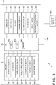
- FIG. 3 is a diagram illustrating a configuration example of a control system according to an embodiment of the present invention.
- a control system 1 includes the work vehicle 10 and the charging station 300. Note that a remote controller for operating a communication terminal possessed by a user that will be described later or the work vehicle 10 may be further included.
- the ECU 44 included in the work vehicle 10 includes a CPU 44a, an I/O 44b, and a memory 44c.
- the I/O 44b inputs and outputs various types of information.
- the memory 44c is a read-only memory (ROM), an electrically erasable programmable read-only memory (EEPROM), a random access memory (RAM), or the like.
- the memory 44c stores a captured image, a work schedule of the work vehicle 10, map information on a work area, various programs for controlling the operation of the work vehicle 10, and the like.
- the ECU 44 reads and executes a program stored in the memory 44c.
- the ECU 44 is connected with the group of various sensors S.
- the sensor group S includes an orientation sensor 46, a GPS sensor 48, a wheel speed sensor 50, an angular speed sensor 52, an acceleration sensor 54, a current sensor 62, and a blade height sensor 64.
- the orientation sensor 46 and the GPS sensor 48 are sensors for acquiring information on the orientation and position of the work vehicle 10.
- the orientation sensor 46 detects the orientation in accordance with terrestrial magnetism.
- the GPS sensor 48 receives a radio wave from a GPS satellite and detects information indicating a current position (latitude and longitude) of the work vehicle 10.
- odometry and an inertial measurement unit (IMU) may be provided.
- the wheel speed sensor 50, the angular speed sensor 52, and the acceleration sensor 54 are sensors for acquiring information regarding a moving state of the work vehicle 10.
- the wheel speed sensor 50 detects the wheel speeds of the left and right rear wheels 16.
- the angular speed sensor 52 detects an angular speed around an axis in the up-and-down direction (z axis in the vertical direction) of the gravity center position of the work vehicle 10.
- the acceleration sensor 54 detects accelerations in the 3 orthogonally triaxial directions of x, y, and z axes acting on the autonomous work vehicle 10.
- the current sensor 62 detects the current consumption (amount of power consumption) of the battery 32.
- the detection result of the current consumption (amount of power consumption) is stored in the memory 44c of the ECU 44.
- the ECU 44 performs returning control for causing the autonomous work vehicle 10 to return to the charging station 300 for charging. Note that a daily work schedule may be stored in the memory 44c, and the returning control may be performed in response to completion of work to be performed on that day.
- the blade height sensor 64 detects a height of the blade 20 with respect to a ground surface GR.
- the detection result of the blade height sensor 64 is output to the ECU 44.
- the blade-height adjustment motor 100 is driven and the blade 20 moves up and down in the up-and-down direction to adjust the height from the ground surface GR.
- Outputs from the group of various sensors S are input into the ECU 44 through the I/O 44b.
- the ECU 44 supplies power from the battery 32 to the travel motor 26, the work motor 22, and the height adjustment motor 100.
- the ECU 44 controls the traveling of the work vehicle 10 by outputting a control value via the I/O 44b and controlling the travel motor 26.
- the height of the blade 20 is adjusted by outputting a control value through the I/O 44b and controlling the height adjustment motor 100.
- the rotation of the blade 20 is controlled by outputting a control value through the I/O 44b to control the work motor 22.
- the I/O 44b can function as a communication interface and can be connected to another device in a wired or wireless manner via a network 150.
- the charging station 300 functions as a charging device for charging a battery (battery 32) of the work vehicle 10.
- the work vehicle 10 is installed in the work area, and can return to the charging station 300 and perform charging by connecting the charging terminal 34 to the charging station 300.
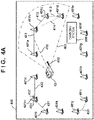
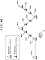
- a virtual line setting method will be described with reference to FIG. 4A .
- a virtual line is an imaginary line connecting markers arranged to define the work area.
- reference numeral 400 denotes a region (for example, the entire site owned by a user) including the work area (for example, a garden) where the work vehicle 10 performs work.
- Reference numerals 401a to 401n denote markers according to the present embodiment. An area surrounded by these markers 401a to 401n is a work area. The work vehicle 10 performs work so as not to deviate from this work area by performing control so as not to deviate to a region beyond the virtual line.
- the work area may be defined by partitioning the entire site using an existing area wire of a type that is embedded in the ground, and disposing markers in a part of the site to provide a non-entry area. That is, the present invention can also be applied to a case where a work area is defined by combining an existing area wire and a marker.
- Reference numeral 402 denotes a traveling direction of the work vehicle 10
- reference numeral 403 denotes a range (for example, an angle of view range) that the work vehicle 10 can recognize by the camera unit 11.
- four markers 401a to 401d are included in the recognizable range.
- the work vehicle 10 sets a virtual line (virtual wire) between two adjacent markers.
- a virtual line 411 is set between the marker 401a and the marker 401b
- a virtual line 412 is set between the marker 401b and the marker 401c
- a virtual line 413 is set between the marker 401c and the marker 401d.
- a virtual line is not set.
- the virtual line is not limited to a straight line.
- a smooth curve may be set like a virtual line 431 set between the marker 401i and the marker 401j.
- Whether two markers are adjacent markers can be determined based on the distance between the markers in the case where it is assumed that the markers are arranged at predetermined distance intervals.
- a predetermined distance range for example, 2.5 m to 3.5 m
- the markers are adjacent markers
- the distance is out of the predetermined distance range it may be determined that the markers are not adjacent markers.
- the line is not set as a virtual line. As a result, it is possible to prevent the work from not being performed in the region of a triangle obtained by connecting the marker 401b, the marker 401c, and the marker 401d.
- the determination method 1 among the plurality of markers, two markers whose distance between the markers is within the predetermined distance range are specified as adjacent markers.
- the predetermined distance range do not have to have an upper limit value or a lower limit value, for example, like 2.5 m or more, 3 m or more, 3 m or less, or 3.5 m or less.
- the method for determining whether two markers are adjacent markers is not limited to a method using the distance between the markers.
- a marker such as the marker 401m in FIG. 4A , including an indicator (For example, 431 and 432) for indicating a direction in which an adjacent marker is present
- each indicator may be detected, and a nearby marker present in the direction indicated by the indicator 431 or 432 may be determined to be an adjacent marker.
- a virtual line 421 is set between the marker 4011 and the marker 401m existing in the direction indicated by the indicator 431, and a virtual line 422 is set between the marker 401n and the marker 401n.
- each marker may be configured to include indicators indicating at least two directions similarly to 401m.
- each marker includes an indicator indicating the direction in which an adjacent marker exists, and a second marker existing in the direction indicated by the indicator of a first marker can be specified as an adjacent marker.
- the marker existing closest to the first marker may be specified as the adjacent marker.
- a marker in a direction indicated by the indicator and within a predetermined distance range for example, 2.5 m to 3.5 m
- the direction indicated by the indicator may be freely changed by the user.
- the direction of the indicator may be adjustable using a rotation mechanism or the like.
- FIG. 4B is an explanatory diagram of a method of determining an adjacent marker in a work area in which an equilateral triangular or square region is formed.
- Reference numeral 450 denotes a region (for example, the entire site owned by a user) including the work area (for example, a garden) where the work vehicle 10 performs work.
- Reference numerals 451a to 451p denote markers according to the present embodiment. An area surrounded by these markers 451a to 451p is a work area. The work vehicle 10 performs work so as not to deviate from the work area.
- the markers 451a to 451p are arranged at predetermined distance (for example, 3 m) intervals.
- an equilateral triangular region is formed by three markers of the marker 451b, the marker 451c, and the marker 451d.
- a square region is formed by four markers of the marker 4511, the marker 451m, the marker 451n, and the marker 451o. If there are such regions, when the determination method 1 is used, the work vehicle 10 cannot move to a region behind the virtual line connecting the marker 451b and the marker 451c and the virtual line connecting the marker 4511 and the marker 451o, so that the work cannot be performed in these regions.
- the two markers are not adjacent markers.
- two markers of the marker 451b and the marker 451d are detected, and the other marker 451c is further detected behind the two markers. Therefore, it is determined that the two markers 451b and 451d are not adjacent markers.
- two markers of the marker 4511 and the marker 451o are detected, and the other markers 451m and 451n are further detected behind the two markers. Therefore, it is determined that the two markers 4511 and 451o are not adjacent markers.
- the determination method 3 when another marker is present in a region behind a line connecting two markers, it is specified that the two markers are not adjacent markers.
- the determination method 3 when the determination method 3 is applied, in the case where another marker at a position far away from the two markers is detected, there is a possibility of erroneous entry to the back region. Therefore, a configuration in which movement to the back region is only possible when the distance to the other marker is calculated and the calculated distance is equal to or less than a predetermined distance (for example, 4 m), or when it is determined that the other marker is a marker adjacent to either one of the two markers on the front side. As a result, it is possible to suppress entry into a region that should not be originally entered.
- a predetermined distance for example, 4 m
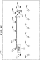
- FIG. 4C is an explanatory diagram of an example of a method of determining adjacent markers.
- Reference numeral 460 denotes a region (for example, the entire site owned by a user) including the work area (for example, a garden) where the work vehicle 10 performs work.
- Reference numerals 461a to 461m denote markers according to the present embodiment. An area surrounded by these markers 461a to 461m is a work area. The work vehicle 10 performs work so as not to deviate from the work area.
- a user 462 Before starting work by the work vehicle 10, a user 462 directly controls the work vehicle 10 by operating a remote controller 463, and moves the work vehicle 10 one lap along each marker. An operation signal from the remote controller 463 is received via the communication unit 35 of the work vehicle 10.
- the work vehicle 10 includes a GPS sensor 48, and stores a trajectory obtained by sequentially tracing each marker according to the operation signal of the remote controller 463 as trajectory information of the work area.
- a trajectory information of the work area can be grasped before the start of the work, it is possible to determine whether or not the two markers are adjacent markers, by determining that markers not following the trajectory are not adjacent markers after the start of the work.
- the trajectory information of the work vehicle 10 is acquired by causing the work vehicle 10 to travel along each of the arranged markers.
- two markers matching the trajectory information among the plurality of markers can be specified as adjacent markers.
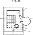
- FIG. 4D is a diagram illustrating an example of drawing something on a map related to a work area displayed on a communication terminal held by a user.
- Reference numeral 470 denotes a communication terminal of the user, which is, for example, a tablet or a smartphone.
- Reference numeral 471 denotes a hand of the user.
- Reference numeral 472 represents map information on the work area displayed on a display screen of the communication terminal 470.
- a map of a site including a home and a garden of the user as viewed from above is displayed.
- Reference numeral 473 denotes a roof of the user's home
- reference numeral 474 denotes a tree space in a site of the user's home.
- FIG. 4E is an external view of a part of the site including the user's home corresponding to the map information of FIG. 4D .
- reference numeral 475 denotes a boundary traced on the map by the user using a finger of the hand 471.
- reference numeral 476 indicates a boundary traced around the tree space by the user using the finger of hand 471.
- a tree spaces 474 is an island excluded from the work area. Note that the boundary may be designated by connecting positions pointed by a finger instead of tracing using the finger.
- the boundary of the work area is designated on a map displayed on the communication terminal 470, and the designated boundary information (information indicating the position of a boundary line) is transmitted to the work vehicle 10.
- the work vehicle 10 can recognize its self-position and orientation using the GPS sensor 48 and the orientation sensor 46, and determine whether or not two detected markers are adjacent markers using the self-position and orientation and the boundary information.
- the work vehicle 10 can determine that a marker 481 and a marker 482 are not adjacent markers from the acquired boundary information.
- the self-position and orientation may be recognized by using, in addition to or instead of the GPS sensor 48 and the orientation sensor 46, an odometry and an inertial measurement unit (IMU).
- IMU inertial measurement unit
- the method of tracing the boundary is not limited to the method in which the user traces the boundary using the finger of the hand 471.
- the user may sequentially point out a plurality of positions of markers on the map along the boundary using the finger of the hand 471 to acquire marker arrangement information as the boundary information.
- the boundary information may be transmitted from the communication terminal 471 to the work vehicle 10.
- the work vehicle 10 can determine that the marker 481 and the marker 482 are not adjacent markers from the boundary information (marker arrangement information).
- the boundary information (for example, arrangement information of a plurality of markers arranged at the boundary of the work area (position information designated by pointing) or information of a boundary line (line traced with a finger) indicating the boundary of the work area) of the work area designated on the map including the work area is acquired.
- two markers matching the boundary information among the plurality of markers can be specified as adjacent markers.
- FIG. 4F illustrates an example of a method using two types of markers.
- Different types For example, different colors, different shapes, and the like
- markers are respectively used for each marker arranged on the boundary of the work area and each marker arranged around the tree space 474 which is an island excluded from the work area.
- the work vehicle 10 can discriminate different types of markers from the features of the markers extracted from the captured image, and the work vehicle 10 can determine that a marker 483 and a marker 484 are not adjacent markers from the captured image.
- the marker is not limited to two types of markers, and in a case where there are a plurality of islands, different types of markers may be used for respective islands. Therefore, the present invention is also applicable to a case where three or more types of markers are used.
- first type markers defining the outer edge of the work area and a plurality of second type markers defining the internal region (island) enclosed by the outer edge and excluded from the work area are used. This allows the first type markers and the second type markers to be identified as not being adjacent markers.
- FIG. 4G is a diagram illustrating an example in which markers are arranged at short intervals in a region having a complicated shape.
- Reference numerals 491a to 491e each denote a marker for a first distance (for example, 3 m) interval.
- Reference numerals 492a to 492f each denote a marker for a second distance (for example, 1 m) interval.
- the first type markers for the first distance interval and the second type markers for the second distance interval are different types of markers having, for example, different colors, shapes, sizes, or the like.
- the marker 491b, the marker 491c, and the marker 491d form an equilateral triangle shape
- the marker 491c, the marker 491d, and the marker 491e also form an equilateral triangle shape.
- a case where only the markers 491a to 491e are arranged in such a complicated shape will be considered.
- the marker 491e is detected at the back, so that the work vehicle can travel in a direction approaching the marker 491e at the back beyond the boundary of the work area connecting the marker 491c and the marker 491d.
- the markers 492a to 492f are further arranged at places having complicated shapes. Accordingly, since the work vehicle 10 further detects the marker 492c and the marker 492d on the line connecting the marker 491c and the marker 491d, it is possible to determine that the two markers (the marker 491c and the marker 491d) are adjacent markers. Therefore, it is possible to prevent the work vehicle 10 from deviating to the back region beyond the boundary of the work area connecting the marker 491c and the marker 491d.
- the two markers 492c and 492d are detected is has been described for the illustrated example, it may be determined that the two markers (the marker 491c and the marker 491d) are adjacent markers when either the marker 492c or the marker 492d is detected on the line connecting the marker 491c and the marker 491d.
- the plurality of first type markers arranged at the first distance intervals and the plurality of second type markers arranged at the second distance intervals shorter than the first distance intervals are used. Accordingly, when one or more second type markers are present between two first type markers among a plurality of first type markers, the two first type markers can be identified as adjacent markers.
- the work vehicle 10 according to the present embodiment sets a virtual line between markers and performs control so that the work vehicle 10 does not deviate to a region beyond the virtual line.
- step S501 the CPU 44a acquires a stereo image captured by the camera unit 11.
- step S502 the CPU 44a acquires a distance image based on the stereo image.
- step S503 the CPU 44a trims an image of one of the first camera 11a and the second camera 11b constituting the camera unit 11. In the present embodiment, an image of the second camera 11b is used.
- step S504 the CPU 44a executes object recognition processing using the trimmed image.
- Features of objects including persons and markers are learned in advance by machine learning, and an object is recognized by comparison with the learning result.
- step S505 the CPU 44a determines whether or not a marker has been recognized as a result of the object recognition processing in step S504. In the case where it is determined that a marker has been recognized, the process proceeds to step S506. In the case where it is determined that a marker has not been recognized, the process proceeds to step S517.
- step S506 the CPU 44a acquires the gravity center position of the marker in the image.
- a specific position of the marker is specified as the gravity center position based on information of the gravity center position of the marker held in advance.
- the gravity center position is merely an example, and is not limited to the gravity center position.
- the position may be a top position of the marker, or may be a ground contact position where the marker and the ground are in contact with each other.
- step S507 the CPU 44a acquires distance information from the work vehicle 10 to the gravity center position of the marker as marker information using the distance image acquired in step S502.
- step S508 the CPU 44a determines whether or not a plurality of markers have been recognized in step S505. In the case where it is determined that a plurality of markers have been recognized, the process proceeds to step S509. In the case where only a single marker has been recognized, the process proceeds to step S515.
- step S509 the CPU 44a determines whether or not two markers included in the plurality of markers are adjacent markers. In the present embodiment, whether or not the distance between the two markers is within a predetermined distance range is determined, and when the distance is within the predetermined distance range, it is determined that the markers are adjacent markers. In the present embodiment, it is assumed that the markers are installed at intervals of 3 m, but the markers are not necessarily arranged at equal intervals of 3 m, and there is a possibility that some deviation occurs. Therefore, it is determined that the markers are adjacent markers if the markers are within the predetermined distance range, for example, in a range of 2.5 m to 3.5 m. In the case where it is determined that the markers are adjacent markers, the process proceeds to step S510. In contrast, in the case where it is determined that the markers are not adjacent markers, the process proceeds to step S511. As a method of determining whether or not the markers, other determination methods described with reference to FIGS. 4A to 4G may be used.
- step S510 the CPU 44a sets a virtual line between the two markers determined to be adjacent markers.
- step S511 the CPU 44a determines whether or not the determination has been completed for all combinations of two markers among the plurality of markers. When the determination is completed for all the combinations, the process proceeds to step S512. In contrast, in the case where there remains a combination for which the determination has not been performed yet, the process returns to step S509, and the determination is performed on a new combination of two markers.
- step S512 the CPU 44a calculates the distance from the work vehicle 10 to a virtual line located ahead of the work vehicle 10 in the traveling direction based on the traveling direction of the work vehicle 10 and the virtual line located ahead in the traveling direction. In the example of FIG. 4A , the distance to an intersection with the virtual line 411 located ahead in the traveling direction 402 is calculated.
- a point O is a current position of the work vehicle 10.
- a point A corresponds to the marker 401a in FIG. 4A
- a point B corresponds to the marker 401b in FIG. 4A .
- X is the length of a line OC.
- the length of a line OA and the length of a line OB can be obtained from the distance image.
- AD OAsin ⁇
- BE OBsin ⁇
- CD OC - OAcos ⁇
- CE OBcos ⁇ - OC hold, and therefore a distance X to the point C can be obtained by AD :
- BE CD :
- step S513 the CPU 44a determines whether or not the distance from the work vehicle 10 to the virtual line located ahead of the work vehicle 10 in the traveling direction is equal to or less than a threshold value (for example, 0.1 m). When it is determined that the distance is equal to or less than the threshold, the process proceeds to S514. In contrast, in the case where the distance is larger than the threshold value, the process proceeds to step S517.
- a threshold value for example, 0.1 m
- step S514 the CPU 44a executes an avoidance operation based on the virtual line. Specifically, when the work vehicle 10 approaches a threshold (for example, 0.1 m) from the virtual line, the work vehicle 10 stops, moves backward, or turns. Accordingly, it is possible to prevent the work vehicle 10 from deviating to a region beyond the virtual line. For example, the work vehicle 10 stops, moves backward, or turns the work vehicle 10 when the distance from the work vehicle 10 to the virtual line 415 becomes equal to or less than the threshold so as not to deviate to the back region beyond the intersection position of the line 415 extending in the traveling direction 415 and the virtual line 411 existing in the traveling direction 415 illustrated in FIG. 4A .
- a threshold for example, 0.1 m
- the work vehicle 10 can perform work without deviating from the work area.
- the turning is to change the traveling direction of the work vehicle 10, and includes moving along a parabolic trajectory when the site is viewed from above, rotating on the spot after stopping at a certain point to change the traveling direction, and going around so as not to enter the region defined by the virtual line.
- control for lowering the traveling speed of the work vehicle 10 heading for the virtual line 415 may be further performed.
- another threshold value for example, 1.5 m
- control for lowering the traveling speed of the work vehicle 10 heading for the virtual line 415 may be further performed.
- step S515 the CPU 44a determines whether or not the distance from the work vehicle 10 to the marker is equal to or less than a threshold.
- the threshold here is, for example, 0.5 m, but is not limited to this value.
- the process proceeds to S516.
- the process proceeds to step S517.
- step S516 the CPU 44a executes the avoidance operation. Specifically, when the work vehicle 10 stops, moves backward, or turns when reaching a threshold distance (for example, 0.5 m) from a marker. Since only one marker is detected, the avoidance operation is performed independently of the virtual line. Thereafter, the process proceeds to step S517.
- a threshold distance for example, 0.5 m
- step S517 the CPU 44a determines whether to end the series of processing. For example, there are a case where the remaining battery charge becomes equal to or lower than a threshold and it is necessary to return to the charging station 300, a case where a predetermined time has elapsed from the start of work, and a case where work in the work area has been completed (for example, the lawn in the work area has been mowed). This also applies to a case where the user operates the power source of the work vehicle 10 to be turned off. In the case where it is determined not to end the series of processing, the process returns to step S501. In contrast, in the case where it is determined to end the series of processing, the processing of FIGS. 5A and 5B is ended.
- the present embodiment two markers are detected, and a virtual line is set between the markers. Then, the avoidance operation is executed so that the work vehicle does not deviate to the back region beyond the virtual line.
- the virtual line virtual wire
- the virtual line virtual wire
- an existing area wire and a marker may be combined to define the work area, and in this case, the area wire does not have to be provided for some regions, so that the cost can be reduced.
- the markers can be freely arranged, the shape of the work area can be flexibly changed. For example, in the case where the user himself/herself works in a part of a garden, there is a case where the work vehicle is not desired to enter the area. In this case, by defining the region so as to be surrounded by markers, it is possible to easily create an area where the work vehicle does not temporarily enter.
- the CPU 44a sets a travel route for the work vehicle 10 to travel according to the set travel route. At that time, the travel route is set such that the virtual line does not exist on the travel route. Accordingly, it is possible to prevent traveling beyond the virtual line and deviating.
- markers on the left and right of the line along the traveling direction may be set as processing targets based on the traveling direction of the work vehicle 10.
- markers on the left and right of the line 415 along the traveling direction 415 instead of processing all the combinations (6 combinations) of the four markers 401a to 401d.
- three combinations of the marker 401a and the marker 401b, the marker 401a and the marker 401c, and the marker 401a and the marker 401d may be set as processing targets, and three combinations of the marker 401b and the marker 401c, the marker 401b and the marker 401d, and the marker 401c and the marker 401d may be excluded from the processing targets. This makes it possible to speed up the processing.
- step S513 when the distance from the work vehicle 10 to the virtual line is larger than the threshold in step S513, the process returns to step S501 through step S517, and the stereo image is acquired again.
- control instead of necessarily returning to step S501 and re-capturing images, control may be performed such that the timing at which the distance from the work vehicle 10 to the virtual line becomes equal to or less than the threshold is estimated on the basis of the traveling speed of the work vehicle 10, and the avoidance operation is executed when that timing arrives.
- a distance from a certain point to the virtual line is calculated, and thereafter, a moving distance from the point is constantly measured by odometry, an inertial measurement unit (IMU), or the like. Then, the operation of the work vehicle 10 may be controlled based on the calculated distance and the moving distance being measured. For example, the avoidance operation may be executed in response to the moving distance being measured reaching the "distance from the point to the virtual line".
- IMU inertial measurement unit
- steps S512 and S513 an example in which the avoidance operation is controlled on the basis of the distance between the work vehicle 10 and the virtual line has been described, but it is not limited to the distance.
- a time required for the work vehicle 10 to reach the virtual line 411 may be calculated, and whether or not the work vehicle 10 has reached the virtual line may be determined on the basis of the calculated time.
- the time may be calculated based on the traveling speed of the work vehicle 10 and the distance from the work vehicle 10 to the virtual line 411.
- the avoidance operation may be controlled to be executed when the difference between the time and the elapsed time is equal to or less than a threshold.
- step S515 an example in which the avoidance operation is controlled on the basis of the distance between the work vehicle 10 and a marker has been described, but it is not limited to the distance.
- a time required for the work vehicle 10 to reach the marker may be calculated, and whether or not the work vehicle 10 has reached the marker may be determined on the basis of the calculated time.
- control may be performed in parallel with repeating the processing by returning to step S501, such that the avoidance operation is separately executed when the timing at which the distance from the work vehicle 10 to the virtual line becomes equal to or less than the threshold arrives.
- the avoidance operation is performed by calculating the distance from the work vehicle to the virtual line and the time until the work vehicle reaches the virtual line are calculated using the distance information.
- marker position information indicating position coordinates of a marker is acquired as marker information
- the avoidance operation is performed by calculating a distance from the work vehicle to the virtual line and a time until the work vehicle reaches the virtual line by using the marker position information and self-position information and orientation information of the work vehicle.
- the work vehicle 10 according to the present embodiment sets a virtual line between markers and performs control so that the work vehicle 10 does not deviate to a region beyond the virtual line. Steps of performing the same processes as those in the flowcharts of FIGS. 5A and 5B are denoted by the same reference numerals. Hereinafter, differences from FIGS. 5A and 5B will be mainly described.
- step S801 the CPU 44a acquires information on the self-position and orientation using the GPS sensor 48 and the orientation sensor 46.
- step S802 the CPU 44a acquires marker position information (position coordinates) of the detected marker as marker information.
- the marker position information is stored in advance in the memory 44c as map information so that the marker position information can be referred to.
- the work vehicle 10 recognizes its self-position and orientation using the GPS sensor 48 and the orientation sensor 46, specifies which marker included in the map information is the marker detected from the image captured by the camera unit 11, and acquires marker position information of the detected marker.
- the marker position information can be specified from the landscape information of the image captured by the camera unit 11.
- landscape information and a marker included in an image are stored in advance in association with distance information to the marker obtained by measurement distance in the landscape. Then, while the work vehicle 10 is caused to travel in the work area, the association is performed at various places and stored as learning information. Then, by referring to this learning information, position coordinates of the marker detected from the image captured by the camera unit 11 can be acquired as marker position information using the self-position and orientation recognized using the GPS sensor 48 and the orientation sensor 46.
- the work vehicle 10 recognizes its self-position and orientation using the GPS sensor 48 and the orientation sensor 46, and acquires, on the basis of an image having parallax (S501 and S502), distance information (distance image) to a marker detected from an image captured by the camera unit 11. Furthermore, an angle (for example, the angle ⁇ or the angle ⁇ in FIG. 6 ) at which the marker exists with respect to the photographing direction of the camera unit 11 is obtained from the position of the marker with respect to the image center of the captured image. Then, a direction in which the marker is present may be specified from the orientation of the work vehicle 10 and the acquired angle, and position coordinates that is ahead along the direction by a distance indicated by the acquired distance information may be acquired as the marker position information.
- an angle for example, the angle ⁇ or the angle ⁇ in FIG. 6
- a direction in which the marker is present may be specified from the orientation of the work vehicle 10 and the acquired angle, and position coordinates that is ahead along the direction by a distance indicated by the acquired distance information may be acquired
- step S803 the CPU 44a determines whether or not two markers included in the plurality of markers are adjacent markers. Also in the present embodiment, the determination method is the same as that in the first embodiment, and thus detailed description thereof is omitted.
- step S804 the CPU 44a calculates the distance from the work vehicle 10 to a virtual line located ahead of the work vehicle 10 in the traveling direction based on the traveling direction of the work vehicle 10 and the virtual line located ahead in the traveling direction. In the example of FIG. 4A , the distance to an intersection with the virtual line 411 located ahead in the traveling direction 402 is calculated.
- a point O is a current position of the work vehicle 10.
- a point A corresponds to the marker 401a in FIG. 4A
- a point B corresponds to the marker 401b in FIG. 4A .
- X is the length of a line OC.
- the position coordinates of the point A, the position coordinates of the point B, and the position coordinates (self-position) of the point O are known, the length of the line OA and the length of the line OB can be obtained from these.
- the distance from the work vehicle 10 to the virtual line 411 located ahead in the traveling direction of the work vehicle 10 is calculated by a procedure similar to the procedure described in the first embodiment.
- marker position information indicating position coordinates of a marker is acquired as marker information, and the avoidance operation is performed by calculating a distance from the work vehicle to the virtual line and a time until the work vehicle reaches the virtual line by using the marker position information and self-position information and orientation information of the work vehicle.
- the operation of the work vehicle can be controlled using the marker position information indicating the position coordinates of the marker and the self-position and orientation of the work vehicle.
- the control performed on the premise that the arrangement of the markers does not change has been described.
- some or all of the markers defining the work area may be removed, fallen, or stolen, and may thus become undetectable.
- the autonomous work machine can continue the work even when some or all of the markers arranged in the past are no longer detected will be described.
- images captured by the method according to the first embodiment or the second embodiment during work are stored in the memory 44c as past captured images (landscape images). Then, when the work is performed again, a past captured image similar to a current captured image that is newly captured is searched and acquired from the memory 44c. Then, markers are detected from the past captured image, the determination of adjacent markers and the setting of a virtual line are performed similarly to the first embodiment and the second embodiment, and the avoidance operation is performed. As described above, by controlling the autonomous work machine using the past captured image similar to the current captured image, the autonomous work machine can continue the work even when some or all of the markers arranged in the past are no longer detected.
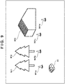
- FIG. 9 is a diagram illustrating a travel example of a work vehicle according to the present embodiment.
- the work vehicle 10 performs work in a work area defined by markers 901a to 901d and the like (only part of the markers defining the work area is illustrated).
- the markers 901a to 901d, a tree 911, a tree 912, and a house 913 exist in the traveling direction of the work vehicle 10, and a landscape image including these is acquired as a captured image by the camera unit 11 of the work vehicle 10.
- FIG. 10 is a diagram illustrating a search example of a past captured image similar to a current captured image. How an image similar to a current captured image 1001 among past captured images 1011 to 1015 and the like is searched and acquired as the past captured image 1011 is illustrated. Regarding determination of the similarity, it is possible to obtain a histogram of pixel values (for example, luminance values), calculate a matching degree between the histograms of the two, and acquire a past captured image in which the matching degree is a predetermined value or high as an image similar to the current captured image. Note that the method of calculating the matching degree between the images is not limited to this example, and any method may be used. In the illustrated example, the marker 901c is included in the similar past captured image 1011, but the marker 901c is not detected from the current captured image 1001.
- a histogram of pixel values for example, luminance values
- the markers are not always arranged as before when the work is to be started. Therefore, in the present embodiment, the work vehicle 10 is controlled by using a past captured image similar to a current captured image such that the lack of a marker can be addressed.
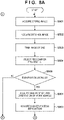
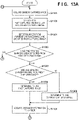
- the work vehicle 10 according to the present embodiment sets a virtual line between markers and performs control so that the work vehicle 10 does not deviate to a region beyond the virtual line.
- the processing is performed by using the past captured image similar to the current captured image.
- step S1101 the CPU 44a acquires a stereo image (captured image) captured by the camera unit 11.
- step S1102 the CPU 44a searches the memory 44c for and specifies a past captured image (for example, one part of a stereo image captured in the past) similar to a current captured image (for example, one part of the stereo image) acquired in step S1101.
- a past captured image for example, one part of a stereo image captured in the past
- a current captured image for example, one part of the stereo image
- step S1103 the CPU 44a detects a marker from the past captured image (landscape image) specified in step S1101.
- a method of detecting a marker from an image is similar to that in the first embodiment.
- step S1104 the CPU 44a determines whether or not a marker has been detected from the past captured image (landscape image) specified in step S1101. In the case where a marker has been detected, the process proceeds to step S1105. In contrast, in the case where a marker has not been detected, the process proceeds to step S1115.
- step S1105 the CPU 44a acquires distance information to the detected marker.
- the CPU 44a acquires the gravity center position of the marker in the image similarly to steps S506 and S507 of the first embodiment.
- the CPU 44a acquires a distance image based on the specified past captured image (stereo image), and acquires distance information from the work vehicle 10 to the gravity center position of the marker.
- the memory 44c stores a past captured image, and another past captured image having parallax with respect to the past captured image in association with each other. Therefore, the distance image can be acquired.
- the position of the marker is not limited to the gravity center position of the marker similarly to the first embodiment.
- Each process of steps S1106 to S1115 is similar to each process of steps S508 to S517 of the first embodiment. Accordingly, the series of processing in FIGS. 11A and 11B are finished.
- a past captured image (landscape image) acquired in a past work is stored. Then, a past captured image similar to a current captured image is specified, a marker is detected from the specified past captured image, and distance information to the marker is acquired using the distance image. Then, a virtual line is set between markers on the basis of the distance information, and the work vehicle 10 is controlled so as not to deviate to a region beyond than the virtual line.
- the autonomous work machine can continue the work even when some or all of the markers arranged in the past are no longer detected from the current captured image. That is, even if some or all of the markers are removed, fallen, or stolen, the work can be continued in the initially defined work area.
- a past captured image and distance information calculated in the past to a marker included in the image may be stored in the memory 44c in association with each other, and the distance information to the marker may be read and acquired from the memory 44c.
- the markers 901a to 901d are detected from the captured image 1011.
- the position of the marker 901a in the image is stored as (Xa, Ya)
- distance information to the marker 901a is stored as Da.
- the position of the marker 901b in the image is stored as (Xb, Yb), and distance information to the marker 901b is stored as Db.
- the position of the marker 901c in the image is stored as (Xc, Yc), and distance information to the marker 901c is stored as Dc.
- the position of the marker 901d in the image is stored as (Xd, Yd), and distance information to the marker 901d is stored as Dd.
- the work vehicle 10 specifies a past captured image similar to the current captured image, and determines whether there is a marker associated with the captured image with reference to the table, thereby performing marker detection processing in steps S1103 and S1104. Then, the processing for acquiring the distance information to the marker in step S1105 is performed with reference to the table for the marker associated with the captured image.
- the distance information may be acquired with reference to a table stored in advance without calculating the distance information to the marker in the image each time using the captured image (stereo image).
- the processing time can be shortened.
- the landscape can change depending on the season (spring, summer, autumn, and winter), the month, the time zone, and the weather.
- season spring, summer, autumn, and winter
- the month the time zone
- the weather for example, there is a possibility that a landscape image stored in a work area with snow piled up in winter is not similar to a current captured image captured in a work area with flourishing greenery in summer. If the state changes extremely, a past captured image similar to the current captured image may not be able to be specified. Therefore, the data to be stored as past captured images may be acquired and stored in the memory 44c periodically, for example, for each season, for each month, for each period of time (for example, evening or morning), for each weather (for example, good weather or rainy weather), or the like. Then, for example, a similar captured image may be specified from the past captured images stored in the same season as the season in which the current captured image is captured.
- the data may be periodically updated. For example, in summer, images captured in spring may be discarded, the markers may be rearranged, and captured image for summer to be stored in the memory 44c may be reacquired.
- the current captured image is not used, a past captured image similar to the current captured image is specified, and the work vehicle 10 is controlled based on the past captured image.
- the fourth embodiment an example will be described in which the case of controlling the work vehicle 10 on the basis of the current captured image and the case of controlling the work vehicle 10 on the basis of the past captured image are switched according to the situation.
- control using the current captured image is performed instead of control using the past captured image.
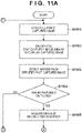
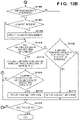
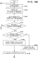
- the work vehicle 10 according to the present embodiment sets a virtual line between markers and performs control so that the work vehicle 10 does not deviate to a region beyond the virtual line. At that time, whether to perform control based on the current captured image or perform control based on a past captured image similar to the current image is switched according to whether or not a marker is missing.
- Each process of steps S1101 and S1102 is similar to each process of steps S1101 and S1102 of the third embodiment.
- step S1301 the CPU 44a detects a marker in the current captured image acquired in step S1101, and also detects a marker in the past captured image specified in step S1102.
- step S1302 the CPU 44a determines whether or not one or more markers have been detected from the past captured image. In the case where one or more markers have been detected, the process proceeds to step S1303. In contrast, when no marker has been detected from the past captured image, no marker should be detected from the current captured image, and thus the process proceeds to step S1115.
- step S1303 the CPU 44a compares the current captured image with the past captured image, and determines whether or not one or more markers are missing in the current captured image. In the case where one or more markers are missing, the process proceeds to step S1304. In contrast, in the case where one or more markers are not missing, the process proceeds to step S1305.
- step S1304 since a marker is missing, the CPU 44a determines to perform control using a past captured image similar to the current captured image.
- step S1305 since no marker is missing, the CPU 44a determines to perform control using the current captured image. If no marker is missing, the accuracy can be improved by using the current captured image in which the current situation is more accurately reflected.
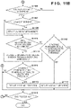
- steps S1105 to S1115 are similar to each process of steps S1105 to S1115 of the third embodiment. However, depending on the determination result in step S1303, whether the image to be used in step S1105 is the current captured image or a past captured image similar to the current captured image varies. Accordingly, the series of processing in FIGS. 13A and 13B are finished.
- past captured images acquired in a past work are stored. Then, a past captured image similar to the current captured image is specified. Next, a marker is detected from each captured image, and whether or not a marker is missing in the current captured image is determined. According to the determination result, whether to perform control based on the current captured image or perform control based on a past captured image similar to the current captured image is switched.
- the autonomous work machine can continue the work even when some or all of the markers arranged in the past are no longer detected from the current captured image. That is, even if some or all of the markers are removed, fallen, or stolen, the work can be continued in the initially defined work area. Further, in the case where no marker is missing, control based on the current captured image is performed, and therefore the accuracy can be improved.
- the current captured image is not used, a past captured image similar to the current captured image is specified, and the work vehicle 10 is controlled based on the past captured image.
- distance information from the work vehicle 10 to the marker is acquired with reference to map information while using a past captured image.
- captured images and the position and orientation of the work vehicle 10 are stored in advance in association with each other.
- the position and orientation of the work vehicle 10 can be measured using, for example, the GPS sensor 48 and the orientation sensor 46. Alternatively, the measurement may be performed by using odometry, an inertial measurement unit (IMU), or the like.
- map information including an arrangement position of a marker is stored in advance. Then, at the time of the current work, a past captured image similar to the current captured image is specified, a marker is detected from the past captured image, and information on the position and direction of the work vehicle 10 associated with the past captured image is acquired. Then, which marker is the detected marker is determined based on the information on the position and orientation of the work vehicle 10 and the map information. If which is the marker is specified, distance information from the work vehicle 10 to the marker can be acquired by using the map information.
- a past captured image 1410 similar to a current captured image 1400 is specified, and four markers 1401 to 1404 are detected from the past captured image 1400.
- the three markers 1401 to 1403 are detected from the current captured image 1400, but the four markers 1401 to 1404 are detected from the past captured image 1410. That is, this is a case where a marker 1413 that has existed before is no longer detected for some reason.
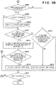
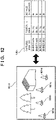
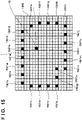
- FIG. 15 position information (position coordinates) of markers 1501a to 1501w arranged to define the work area is known.
- the markers 1501b, 1501c, 1501d, and 1501e in the map information stored in advance correspond to the markers 1411 to 1414. Since the determined positions of the markers 1501b, 1501c, 1501d, and 1501e on the map are known, distance information between the work vehicle 10 and these markers can be acquired by calculating distance between coordinates.
- the position information (position coordinates) of the markers 1501a to 1501w can be acquired by calculating distance information of the markers detected from the captured image on the basis of the stereo image and plotting the distance information on the map while the work vehicle 10 is working.
- the map information acquired in advance is stored in the memory 44c, and the map information is read and used at the time of the current work.
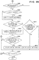
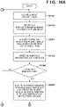
- the work vehicle 10 according to the present embodiment sets a virtual line between markers and performs control so that the work vehicle 10 does not deviate to a region beyond the virtual line.
- Each process of steps S1101 to S1104 is similar to each process of steps S1101 to S1104 of FIG. 11A .
- step S1601 the CPU 44a acquires, from the memory 44c, information indicating the position and orientation of the work vehicle 10 stored in association with the past captured image specified in step S1102.
- step S1602 the CPU 44a acquires distance information to the detected marker based on the information indicating the position and orientation of the work vehicle 10 acquired in step S1601 and map information in which marker positions are plotted in advance and the marker positions are known.
- Each process of steps S1106 to S1115 is similar to each process of steps S1106 to S1115 of FIG. 11B . Accordingly, the series of processing in FIGS. 16A and 16B are finished.
- past captured images acquired in the past work and the position and direction of the work vehicle 10 at the time of the imaging are stored in the memory 44c in association with each other.
- map information including arrangement information of markers is stored in the memory 44c in advance. Then, at the time of the current imaging, a past captured image similar to the current captured image is specified, and information on the position and orientation of the work vehicle 10 associated with the past captured image is acquired.
- a marker is detected from the past captured image similar to the current captured image. Further, which marker in the map the detected marker corresponds to is determined based on the acquired position and orientation of the work vehicle 10 and the map information. Then, distance information to the marker is acquired from position coordinates of the marker on the map and position coordinates of the work vehicle 10.
- the autonomous work machine can continue the work even when some or all of the markers arranged in the past are no longer detected from the current captured image. That is, even if some or all of the markers are removed, fallen, or stolen, the work can be continued in the initially defined work area.
- the distance information to the marker is acquired from the arrangement information of the marker and the position information of the work vehicle 10, it is not necessary to acquire a distance image and calculate the distance information.
- the current captured image is compared with a past captured image similar to the current captured image to determine whether or not any marker is missing, and when a marker is missing, the marker in the past captured image missing in the current captured image is arranged as a virtual marker at the corresponding position in the current captured image. Then, distance information to each marker is acquired on the basis of the marker detected from the current captured image and the virtual marker arranged in the current captured image, and a virtual line is set between the markers.
- the use of the information of the marker detected from the current captured image enables more highly accurate control reflecting the current situation, but the lack of the marker may cause deviation from the work area. Therefore, for the missing marker, information on the marker from the similar past captured image is used. As a result, the marker information of the past captured image can be used together for the lack while using the marker information of the current captured image as much as possible. Therefore, it is possible to realize highly accurate control reflecting the current situation as much as possible while suppressing the deviation from the work area.
- FIG. 17 is a diagram illustrating an example of superimposed arrangement of a virtual marker according to the present embodiment.
- Reference numeral 1700 denotes a current captured image. Three markers 1701 to 1703 are detected from the current captured image 1700. Meanwhile, as a result of specifying a past captured image 1710 similar to the current captured image 1700 and detecting markers, four markers of markers 1711 to 1714 are detected.
- the current captured image 1700 is compared with the past captured image 1710 similar to the current captured image 1700, it can be determined that a marker that should correspond to the marker 1713 is missing in the current captured image 1700. Therefore, a corrected image 1720 is acquired by arranging a virtual marker 1721 at a position in the current image 1700 corresponding to an in-image position of the marker 1713 detected from the past captured image 1710.
- the work vehicle 10 is controlled using the corrected image 1720.
- the distance information of each marker can be acquired from the current image 1700 or the corrected image 1720 by the method described in the first embodiment.
- the distance information of the virtual marker 1721 can be acquired by acquiring the distance information of the marker 1713 from the past captured image 1710 by the method described in the third embodiment. Then, a virtual line connecting markers (adjacent markers) included in the corrected image 1720 is set using the acquired distance information of the markers.
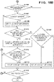
- the work vehicle 10 according to the present embodiment sets a virtual line between markers and performs control so that the work vehicle 10 does not deviate to a region beyond the virtual line. At this time, whether to perform control based on the current captured image or perform control based on both the current captured image and a past captured image similar to the current image is switched according to whether or not a marker is missing.
- steps S1101, S1102, S1302, S1303, and S1305 is similar to each corresponding process of FIG. 13A .
- step S1801 the CPU 44a specifies a marker that is missing in the current captured image by using the past captured image specified in step S1102 that is similar to the current captured image. Then, a virtual marker corresponding to the marker is arranged at a position in the current captured image corresponding to the position of the marker in the specified past captured image, and thus a corrected image is generated.
- steps S1105 to S1115 are similar to each corresponding process of FIGS. 13A and 13B .
- the distance information of each of the marker detected from the current captured image and the virtual marker superimposed and arranged on the current captured image is acquired.
- the distance information of the marker detected from the current captured image can be acquired by, for example, the method described in the first embodiment.
- the distance information of the virtual marker the distance information of the corresponding marker in the past captured image similar to the current captured image can be acquired by, for example, the method described in the third embodiment and used as the distance information of the virtual marker.
- the work vehicle 10 can perform the work without deviating from the work area by performing the processing on the marker and the virtual marker in the current captured image.
- whether to perform control based on the current captured image or perform control based on both the current captured image and a past captured image similar to the current image is switched according to whether or not a marker is missing will be described. Then, in the case where a marker is missing, the marker missing in the current captured image is specified from the past captured image, and a virtual marker corresponding to the marker is superimposed and arranged at a corresponding position in the current captured image. Furthermore, a virtual line is set on the basis of the distance information of the marker detected from the current captured image and the distance information of the virtual marker, and control is performed so as not to deviate to a region beyond the virtual line.
- the marker information of the current captured image can be used as much as possible, and the marker information of the past captured image can be used together for the lack. Therefore, it is possible to realize highly accurate control reflecting the current situation as much as possible while suppressing the deviation from the work area.
- a virtual line connecting an actual marker (real marker) and a virtual marker in the current captured image may be set.
- a different threshold may be applied depending on whether the virtual line connects real markers, whether the virtual line connects virtual markers, and whether the virtual line connects a real marker and a virtual marker.
- a threshold for a virtual line connecting real markers is set as a first threshold value
- a threshold for a virtual line connecting a real marker and a virtual marker is set as a second threshold
- a threshold for a virtual line connecting virtual markers is set as a third threshold value.
- the second threshold may be larger than the first threshold. Since the accuracy of the virtual line connecting a real marker and a virtual marker is assumed to be lower than the accuracy of the virtual line connecting real markers, it is possible to suppress the deviation from the work area by performing the avoidance operation before approaching the virtual line much.
- the third threshold may be larger than the first threshold. Since the accuracy of the virtual line connecting virtual markers is assumed to be lower than the accuracy of the virtual line connecting real markers, it is possible to suppress the deviation from the work area by performing the avoidance operation before approaching the virtual line much.
- the third threshold > the second threshold > the first threshold may be set.
- the lawn mower has been described as an example of the autonomous work machine, but the autonomous work machine is not limited to the lawn mower.
- the present invention can also be applied to other types of autonomous work machines such as an autonomous snow removing machines, golf ball collectors, outboard motors, and the like.
- the processing of other embodiments may be applied or used in combination.
- markers having a shape like a cone has been described as an example in each embodiment described above, the type of marker is not limited to the illustrated example.
- the marker may be a thin flat plate-shaped marker that can be attached to a wall surface of a building or the like.
- the work vehicle has been described as an autonomous work machine that controls itself in each embodiment described above, for example, an external control device different from the work vehicle, such as a server, may have a function of performing the processing of the embodiments described above.
- an external control device different from the work vehicle, such as a server
- some or all functions of the work vehicle described in each embodiment described above can be realized on the control device by the control device acquiring information of past captured images captured by the camera unit of the work vehicle or the like from the work vehicle by communication and transmitting various control information to the work vehicle.
- control device can be realized by a computer.
Landscapes
- Engineering & Computer Science (AREA)
- Physics & Mathematics (AREA)
- General Physics & Mathematics (AREA)
- Radar, Positioning & Navigation (AREA)
- Remote Sensing (AREA)
- Automation & Control Theory (AREA)
- Aviation & Aerospace Engineering (AREA)
- Multimedia (AREA)
- Theoretical Computer Science (AREA)
- Electromagnetism (AREA)
- Computer Vision & Pattern Recognition (AREA)
- Life Sciences & Earth Sciences (AREA)
- Environmental Sciences (AREA)
- Control Of Position, Course, Altitude, Or Attitude Of Moving Bodies (AREA)
- Robotics (AREA)
Applications Claiming Priority (1)
| Application Number | Priority Date | Filing Date | Title |
|---|---|---|---|
| PCT/JP2019/028901 WO2021014585A1 (ja) | 2019-07-23 | 2019-07-23 | 自律作業機、制御装置、自律作業機の制御方法、制御装置の動作方法及びプログラム |
Publications (3)
| Publication Number | Publication Date |
|---|---|
| EP4006681A1 true EP4006681A1 (de) | 2022-06-01 |
| EP4006681A4 EP4006681A4 (de) | 2022-11-16 |
| EP4006681B1 EP4006681B1 (de) | 2024-10-16 |
Family
ID=74193565
Family Applications (1)
| Application Number | Title | Priority Date | Filing Date |
|---|---|---|---|
| EP19938129.4A Active EP4006681B1 (de) | 2019-07-23 | 2019-07-23 | Autonome arbeitsmaschine, verfahren zur steuerung einer autonomen arbeitsmaschine |
Country Status (4)
| Country | Link |
|---|---|
| US (1) | US12228933B2 (de) |
| EP (1) | EP4006681B1 (de) |
| JP (1) | JP7462642B2 (de) |
| WO (1) | WO2021014585A1 (de) |
Families Citing this family (6)
| Publication number | Priority date | Publication date | Assignee | Title |
|---|---|---|---|---|
| US11604476B1 (en) * | 2018-10-05 | 2023-03-14 | Glydways Inc. | Road-based vehicle guidance system |
| EP4006681B1 (de) | 2019-07-23 | 2024-10-16 | Honda Motor Co., Ltd. | Autonome arbeitsmaschine, verfahren zur steuerung einer autonomen arbeitsmaschine |
| CN111427357A (zh) * | 2020-04-14 | 2020-07-17 | 北京石头世纪科技股份有限公司 | 一种机器人避障方法、装置和存储介质 |
| JP7408495B2 (ja) * | 2020-06-18 | 2024-01-05 | 株式会社やまびこ | 作業ロボットシステム |
| EP4336296A4 (de) * | 2021-05-19 | 2025-03-05 | Yamabiko Corporation | Roboterarbeitsvorrichtung |
| JP2025057665A (ja) * | 2023-09-28 | 2025-04-09 | キヤノン株式会社 | 情報処理方法、情報処理システムおよびプログラム |
Family Cites Families (27)
| Publication number | Priority date | Publication date | Assignee | Title |
|---|---|---|---|---|
| JPH0371313A (ja) * | 1989-08-11 | 1991-03-27 | Mitsubishi Agricult Mach Co Ltd | 作業用走行車の指標装置 |
| JP2007094743A (ja) * | 2005-09-28 | 2007-04-12 | Zmp:Kk | 自律移動型ロボットとそのシステム |
| JP2007213293A (ja) | 2006-02-09 | 2007-08-23 | Advanced Telecommunication Research Institute International | 誘導装置 |
| JP5112666B2 (ja) | 2006-09-11 | 2013-01-09 | 株式会社日立製作所 | 移動装置 |
| KR101337534B1 (ko) * | 2007-07-24 | 2013-12-06 | 삼성전자주식회사 | 이동 로봇의 위치 인식 장치 및 방법 |
| JP5262148B2 (ja) * | 2008-02-05 | 2013-08-14 | 日本電気株式会社 | ランドマーク検出装置および方法ならびにプログラム |
| JP5066123B2 (ja) | 2009-03-24 | 2012-11-07 | 日立オートモティブシステムズ株式会社 | 車両運転支援装置 |
| EP2885683A4 (de) | 2012-08-14 | 2016-06-01 | Husqvarna Ab | Grenzdefinitionssystem für ein roboterfahrzeug |
| US9298188B2 (en) * | 2013-01-28 | 2016-03-29 | Caterpillar Inc. | Machine control system having autonomous edge dumping |
| EP2884364B1 (de) * | 2013-12-12 | 2018-09-26 | Hexagon Technology Center GmbH | Autonomes Gartenarbeitsfahrzeug mit Kamera |
| EP3234718B1 (de) * | 2014-12-17 | 2018-10-24 | Husqvarna AB | Bewegungsgrenzenlernendes roboterfahrzeug |
| JP5973608B1 (ja) * | 2015-03-27 | 2016-08-23 | 本田技研工業株式会社 | 無人作業車の制御装置 |
| JP6776513B2 (ja) | 2015-08-19 | 2020-10-28 | ソニー株式会社 | 車両制御装置と車両制御方法と情報処理装置および交通情報提供システム |
| GB201518652D0 (en) | 2015-10-21 | 2015-12-02 | F Robotics Acquisitions Ltd | Domestic robotic system and method |
| JP2017091246A (ja) | 2015-11-11 | 2017-05-25 | 有限会社曽田農機設計事務所 | 刈取ロボット及びそれを用いた自動刈取システム |
| JP2017107456A (ja) | 2015-12-10 | 2017-06-15 | 国立大学法人豊橋技術科学大学 | 自律走行ロボットシステム |
| JP6651961B2 (ja) * | 2016-03-03 | 2020-02-19 | 株式会社リコー | 農作業用装置および農作業用装置の制御方法 |
| JP6733225B2 (ja) * | 2016-03-08 | 2020-07-29 | 株式会社リコー | 画像処理装置、撮像装置、移動体機器制御システム、画像処理方法、及びプログラム |
| JP6235640B2 (ja) * | 2016-03-18 | 2017-11-22 | 本田技研工業株式会社 | 無人走行作業車 |
| JP6947171B2 (ja) * | 2016-04-28 | 2021-10-13 | 愛知製鋼株式会社 | 運転支援システム |
| JP2018102705A (ja) * | 2016-12-27 | 2018-07-05 | 本田技研工業株式会社 | 感情改善装置および感情改善方法 |
| JP2019004792A (ja) | 2017-06-26 | 2019-01-17 | 株式会社クボタ | 作業場の走行管理システム |
| JP6876547B2 (ja) | 2017-07-03 | 2021-05-26 | ヤンマーパワーテクノロジー株式会社 | 自律走行システム |
| US10872246B2 (en) | 2017-09-07 | 2020-12-22 | Regents Of The University Of Minnesota | Vehicle lane detection system |
| WO2019124225A1 (ja) | 2017-12-18 | 2019-06-27 | 株式会社クボタ | 農作業車、作業車衝突警戒システム及び作業車 |
| US20210027489A1 (en) * | 2018-03-23 | 2021-01-28 | Honda Motor Co., Ltd. | Placement position notification system |
| EP4006681B1 (de) | 2019-07-23 | 2024-10-16 | Honda Motor Co., Ltd. | Autonome arbeitsmaschine, verfahren zur steuerung einer autonomen arbeitsmaschine |
-
2019
- 2019-07-23 EP EP19938129.4A patent/EP4006681B1/de active Active
- 2019-07-23 WO PCT/JP2019/028901 patent/WO2021014585A1/ja not_active Ceased
- 2019-07-23 JP JP2021534462A patent/JP7462642B2/ja active Active
-
2022
- 2022-01-13 US US17/575,606 patent/US12228933B2/en active Active
Also Published As
| Publication number | Publication date |
|---|---|
| JPWO2021014585A1 (de) | 2021-01-28 |
| EP4006681A4 (de) | 2022-11-16 |
| US20220137631A1 (en) | 2022-05-05 |
| WO2021014585A1 (ja) | 2021-01-28 |
| EP4006681B1 (de) | 2024-10-16 |
| JP7462642B2 (ja) | 2024-04-05 |
| US12228933B2 (en) | 2025-02-18 |
Similar Documents
| Publication | Publication Date | Title |
|---|---|---|
| EP4006681B1 (de) | Autonome arbeitsmaschine, verfahren zur steuerung einer autonomen arbeitsmaschine | |
| EP4006682B1 (de) | Autonome arbeitsmaschine, steuerungsverfahren für autonome arbeitsmaschine und programm | |
| EP3603372B1 (de) | Beweglicher roboter, verfahren zur steuerung davon und endgerät | |
| CN114937258B (zh) | 割草机器人的控制方法、割草机器人以及计算机存储介质 | |
| US12608005B2 (en) | Smart mower and smart mowing system | |
| US11076529B2 (en) | Intelligent mowing system | |
| CN113126613B (zh) | 智能割草系统及其自主建图方法 | |
| CN115826585B (zh) | 使用视觉系统的自主机器导航和训练 | |
| US10321625B2 (en) | Autonomous working machine such as autonomous lawn mower | |
| EP3084541B1 (de) | Navigation für ein robotisches arbeitswerkzeug | |
| US20230008134A1 (en) | Robotic work tool system and method for defining a working area perimeter | |
| JPWO2020105125A1 (ja) | 自律作業機、自律作業機の制御方法及びプログラム | |
| CN111199677B (zh) | 一种室外区域的工作地图自动建立方法,装置,存储介质及工作设备 | |
| EP4206849B1 (de) | Autonome mobile gartenvorrichtung und verfahren zur steuerung davon | |
| CN109782770A (zh) | 一种割草机自主充电的方法 | |
| CN114322980A (zh) | 获取位置坐标及绘制电子地图的方法、计算机可读存储介质和自主作业设备 | |
| CN116466693B (zh) | 地图处理方法、自移动的园艺设备、以及自动割草机 | |
| CN115933681B (zh) | 基于激光和视觉方案的工作区域圈定方法及室外机器人 | |
| EP4381925A1 (de) | Verbesserte erkennung eines solarpaneels für ein robotisches arbeitswerkzeug | |
| CN121713756A (zh) | 一种园艺机器人的控制方法和园艺机器人 | |
| CN120380924A (zh) | 自移动割草机和自移动割草机的建边方法 |
Legal Events
| Date | Code | Title | Description |
|---|---|---|---|
| STAA | Information on the status of an ep patent application or granted ep patent |
Free format text: STATUS: THE INTERNATIONAL PUBLICATION HAS BEEN MADE |
|
| PUAI | Public reference made under article 153(3) epc to a published international application that has entered the european phase |
Free format text: ORIGINAL CODE: 0009012 |
|
| STAA | Information on the status of an ep patent application or granted ep patent |
Free format text: STATUS: REQUEST FOR EXAMINATION WAS MADE |
|
| 17P | Request for examination filed |
Effective date: 20220119 |
|
| AK | Designated contracting states |
Kind code of ref document: A1 Designated state(s): AL AT BE BG CH CY CZ DE DK EE ES FI FR GB GR HR HU IE IS IT LI LT LU LV MC MK MT NL NO PL PT RO RS SE SI SK SM TR |
|
| DAV | Request for validation of the european patent (deleted) | ||
| DAX | Request for extension of the european patent (deleted) | ||
| A4 | Supplementary search report drawn up and despatched |
Effective date: 20221013 |
|
| RIC1 | Information provided on ipc code assigned before grant |
Ipc: G05D 1/02 20200101AFI20221010BHEP |
|
| STAA | Information on the status of an ep patent application or granted ep patent |
Free format text: STATUS: EXAMINATION IS IN PROGRESS |
|
| 17Q | First examination report despatched |
Effective date: 20230803 |
|
| REG | Reference to a national code |
Ref country code: DE Ref legal event code: R079 Free format text: PREVIOUS MAIN CLASS: G05D0001020000 Ipc: G05D0001000000 Ref document number: 602019060664 Country of ref document: DE |
|
| GRAP | Despatch of communication of intention to grant a patent |
Free format text: ORIGINAL CODE: EPIDOSNIGR1 |
|
| STAA | Information on the status of an ep patent application or granted ep patent |
Free format text: STATUS: GRANT OF PATENT IS INTENDED |
|
| RIC1 | Information provided on ipc code assigned before grant |
Ipc: G05D 1/00 20060101AFI20240131BHEP |
|
| INTG | Intention to grant announced |
Effective date: 20240223 |
|
| GRAJ | Information related to disapproval of communication of intention to grant by the applicant or resumption of examination proceedings by the epo deleted |
Free format text: ORIGINAL CODE: EPIDOSDIGR1 |
|
| STAA | Information on the status of an ep patent application or granted ep patent |
Free format text: STATUS: EXAMINATION IS IN PROGRESS |
|
| GRAP | Despatch of communication of intention to grant a patent |
Free format text: ORIGINAL CODE: EPIDOSNIGR1 |
|
| INTC | Intention to grant announced (deleted) | ||
| STAA | Information on the status of an ep patent application or granted ep patent |
Free format text: STATUS: GRANT OF PATENT IS INTENDED |
|
| INTG | Intention to grant announced |
Effective date: 20240516 |
|
| GRAS | Grant fee paid |
Free format text: ORIGINAL CODE: EPIDOSNIGR3 |
|
| GRAA | (expected) grant |
Free format text: ORIGINAL CODE: 0009210 |
|
| STAA | Information on the status of an ep patent application or granted ep patent |
Free format text: STATUS: THE PATENT HAS BEEN GRANTED |
|
| AK | Designated contracting states |
Kind code of ref document: B1 Designated state(s): AL AT BE BG CH CY CZ DE DK EE ES FI FR GB GR HR HU IE IS IT LI LT LU LV MC MK MT NL NO PL PT RO RS SE SI SK SM TR |
|
| REG | Reference to a national code |
Ref country code: GB Ref legal event code: FG4D |
|
| REG | Reference to a national code |
Ref country code: CH Ref legal event code: EP |
|
| REG | Reference to a national code |
Ref country code: IE Ref legal event code: FG4D |
|
| REG | Reference to a national code |
Ref country code: DE Ref legal event code: R096 Ref document number: 602019060664 Country of ref document: DE |
|
| REG | Reference to a national code |
Ref country code: LT Ref legal event code: MG9D |
|
| REG | Reference to a national code |
Ref country code: NL Ref legal event code: MP Effective date: 20241016 |
|
| REG | Reference to a national code |
Ref country code: AT Ref legal event code: MK05 Ref document number: 1733428 Country of ref document: AT Kind code of ref document: T Effective date: 20241016 |
|
| PG25 | Lapsed in a contracting state [announced via postgrant information from national office to epo] |
Ref country code: NL Free format text: LAPSE BECAUSE OF FAILURE TO SUBMIT A TRANSLATION OF THE DESCRIPTION OR TO PAY THE FEE WITHIN THE PRESCRIBED TIME-LIMIT Effective date: 20241016 |
|
| PG25 | Lapsed in a contracting state [announced via postgrant information from national office to epo] |
Ref country code: NL Free format text: LAPSE BECAUSE OF FAILURE TO SUBMIT A TRANSLATION OF THE DESCRIPTION OR TO PAY THE FEE WITHIN THE PRESCRIBED TIME-LIMIT Effective date: 20241016 |
|
| PG25 | Lapsed in a contracting state [announced via postgrant information from national office to epo] |
Ref country code: PT Free format text: LAPSE BECAUSE OF FAILURE TO SUBMIT A TRANSLATION OF THE DESCRIPTION OR TO PAY THE FEE WITHIN THE PRESCRIBED TIME-LIMIT Effective date: 20250217 Ref country code: HR Free format text: LAPSE BECAUSE OF FAILURE TO SUBMIT A TRANSLATION OF THE DESCRIPTION OR TO PAY THE FEE WITHIN THE PRESCRIBED TIME-LIMIT Effective date: 20241016 Ref country code: IS Free format text: LAPSE BECAUSE OF FAILURE TO SUBMIT A TRANSLATION OF THE DESCRIPTION OR TO PAY THE FEE WITHIN THE PRESCRIBED TIME-LIMIT Effective date: 20250216 |
|
| PG25 | Lapsed in a contracting state [announced via postgrant information from national office to epo] |
Ref country code: FI Free format text: LAPSE BECAUSE OF FAILURE TO SUBMIT A TRANSLATION OF THE DESCRIPTION OR TO PAY THE FEE WITHIN THE PRESCRIBED TIME-LIMIT Effective date: 20241016 |
|
| PG25 | Lapsed in a contracting state [announced via postgrant information from national office to epo] |
Ref country code: BG Free format text: LAPSE BECAUSE OF FAILURE TO SUBMIT A TRANSLATION OF THE DESCRIPTION OR TO PAY THE FEE WITHIN THE PRESCRIBED TIME-LIMIT Effective date: 20241016 |
|
| PG25 | Lapsed in a contracting state [announced via postgrant information from national office to epo] |
Ref country code: ES Free format text: LAPSE BECAUSE OF FAILURE TO SUBMIT A TRANSLATION OF THE DESCRIPTION OR TO PAY THE FEE WITHIN THE PRESCRIBED TIME-LIMIT Effective date: 20241016 |
|
| PG25 | Lapsed in a contracting state [announced via postgrant information from national office to epo] |
Ref country code: NO Free format text: LAPSE BECAUSE OF FAILURE TO SUBMIT A TRANSLATION OF THE DESCRIPTION OR TO PAY THE FEE WITHIN THE PRESCRIBED TIME-LIMIT Effective date: 20250116 |
|
| PG25 | Lapsed in a contracting state [announced via postgrant information from national office to epo] |
Ref country code: GR Free format text: LAPSE BECAUSE OF FAILURE TO SUBMIT A TRANSLATION OF THE DESCRIPTION OR TO PAY THE FEE WITHIN THE PRESCRIBED TIME-LIMIT Effective date: 20250117 Ref country code: LV Free format text: LAPSE BECAUSE OF FAILURE TO SUBMIT A TRANSLATION OF THE DESCRIPTION OR TO PAY THE FEE WITHIN THE PRESCRIBED TIME-LIMIT Effective date: 20241016 Ref country code: AT Free format text: LAPSE BECAUSE OF FAILURE TO SUBMIT A TRANSLATION OF THE DESCRIPTION OR TO PAY THE FEE WITHIN THE PRESCRIBED TIME-LIMIT Effective date: 20241016 |
|
| PG25 | Lapsed in a contracting state [announced via postgrant information from national office to epo] |
Ref country code: PL Free format text: LAPSE BECAUSE OF FAILURE TO SUBMIT A TRANSLATION OF THE DESCRIPTION OR TO PAY THE FEE WITHIN THE PRESCRIBED TIME-LIMIT Effective date: 20241016 |
|
| PG25 | Lapsed in a contracting state [announced via postgrant information from national office to epo] |
Ref country code: RS Free format text: LAPSE BECAUSE OF FAILURE TO SUBMIT A TRANSLATION OF THE DESCRIPTION OR TO PAY THE FEE WITHIN THE PRESCRIBED TIME-LIMIT Effective date: 20250116 |
|
| PG25 | Lapsed in a contracting state [announced via postgrant information from national office to epo] |
Ref country code: SM Free format text: LAPSE BECAUSE OF FAILURE TO SUBMIT A TRANSLATION OF THE DESCRIPTION OR TO PAY THE FEE WITHIN THE PRESCRIBED TIME-LIMIT Effective date: 20241016 |
|
| PG25 | Lapsed in a contracting state [announced via postgrant information from national office to epo] |
Ref country code: DK Free format text: LAPSE BECAUSE OF FAILURE TO SUBMIT A TRANSLATION OF THE DESCRIPTION OR TO PAY THE FEE WITHIN THE PRESCRIBED TIME-LIMIT Effective date: 20241016 |
|
| REG | Reference to a national code |
Ref country code: DE Ref legal event code: R097 Ref document number: 602019060664 Country of ref document: DE |
|
| PG25 | Lapsed in a contracting state [announced via postgrant information from national office to epo] |
Ref country code: EE Free format text: LAPSE BECAUSE OF FAILURE TO SUBMIT A TRANSLATION OF THE DESCRIPTION OR TO PAY THE FEE WITHIN THE PRESCRIBED TIME-LIMIT Effective date: 20241016 |
|
| RAP4 | Party data changed (patent owner data changed or rights of a patent transferred) |
Owner name: HONDA MOTOR CO., LTD. |
|
| PG25 | Lapsed in a contracting state [announced via postgrant information from national office to epo] |
Ref country code: RO Free format text: LAPSE BECAUSE OF FAILURE TO SUBMIT A TRANSLATION OF THE DESCRIPTION OR TO PAY THE FEE WITHIN THE PRESCRIBED TIME-LIMIT Effective date: 20241016 |
|
| PG25 | Lapsed in a contracting state [announced via postgrant information from national office to epo] |
Ref country code: SK Free format text: LAPSE BECAUSE OF FAILURE TO SUBMIT A TRANSLATION OF THE DESCRIPTION OR TO PAY THE FEE WITHIN THE PRESCRIBED TIME-LIMIT Effective date: 20241016 |
|
| PG25 | Lapsed in a contracting state [announced via postgrant information from national office to epo] |
Ref country code: CZ Free format text: LAPSE BECAUSE OF FAILURE TO SUBMIT A TRANSLATION OF THE DESCRIPTION OR TO PAY THE FEE WITHIN THE PRESCRIBED TIME-LIMIT Effective date: 20241016 |
|
| PG25 | Lapsed in a contracting state [announced via postgrant information from national office to epo] |
Ref country code: IT Free format text: LAPSE BECAUSE OF FAILURE TO SUBMIT A TRANSLATION OF THE DESCRIPTION OR TO PAY THE FEE WITHIN THE PRESCRIBED TIME-LIMIT Effective date: 20241016 |
|
| PLBE | No opposition filed within time limit |
Free format text: ORIGINAL CODE: 0009261 |
|
| STAA | Information on the status of an ep patent application or granted ep patent |
Free format text: STATUS: NO OPPOSITION FILED WITHIN TIME LIMIT |
|
| PG25 | Lapsed in a contracting state [announced via postgrant information from national office to epo] |
Ref country code: SE Free format text: LAPSE BECAUSE OF FAILURE TO SUBMIT A TRANSLATION OF THE DESCRIPTION OR TO PAY THE FEE WITHIN THE PRESCRIBED TIME-LIMIT Effective date: 20241016 |
|
| 26N | No opposition filed |
Effective date: 20250717 |
|
| PGFP | Annual fee paid to national office [announced via postgrant information from national office to epo] |
Ref country code: DE Payment date: 20250729 Year of fee payment: 7 |
|
| REG | Reference to a national code |
Ref country code: CH Ref legal event code: H13 Free format text: ST27 STATUS EVENT CODE: U-0-0-H10-H13 (AS PROVIDED BY THE NATIONAL OFFICE) Effective date: 20260224 |
|
| PG25 | Lapsed in a contracting state [announced via postgrant information from national office to epo] |
Ref country code: LU Free format text: LAPSE BECAUSE OF NON-PAYMENT OF DUE FEES Effective date: 20250723 |
|
| GBPC | Gb: european patent ceased through non-payment of renewal fee |
Effective date: 20250723 |
|
| REG | Reference to a national code |
Ref country code: BE Ref legal event code: MM Effective date: 20250731 |
|
| PG25 | Lapsed in a contracting state [announced via postgrant information from national office to epo] |
Ref country code: GB Free format text: LAPSE BECAUSE OF NON-PAYMENT OF DUE FEES Effective date: 20250723 |
|
| PG25 | Lapsed in a contracting state [announced via postgrant information from national office to epo] |
Ref country code: BE Free format text: LAPSE BECAUSE OF NON-PAYMENT OF DUE FEES Effective date: 20250731 |
|
| PG25 | Lapsed in a contracting state [announced via postgrant information from national office to epo] |
Ref country code: FR Free format text: LAPSE BECAUSE OF NON-PAYMENT OF DUE FEES Effective date: 20250731 |
|
| PG25 | Lapsed in a contracting state [announced via postgrant information from national office to epo] |
Ref country code: CH Free format text: LAPSE BECAUSE OF NON-PAYMENT OF DUE FEES Effective date: 20250731 |