EP4006693A1 - Dispositif de connexion des appareils électroniques - Google Patents
Dispositif de connexion des appareils électroniques Download PDFInfo
- Publication number
- EP4006693A1 EP4006693A1 EP21210778.3A EP21210778A EP4006693A1 EP 4006693 A1 EP4006693 A1 EP 4006693A1 EP 21210778 A EP21210778 A EP 21210778A EP 4006693 A1 EP4006693 A1 EP 4006693A1
- Authority
- EP
- European Patent Office
- Prior art keywords
- holding
- carrying
- screens
- peripheral devices
- another
- Prior art date
- Legal status (The legal status is an assumption and is not a legal conclusion. Google has not performed a legal analysis and makes no representation as to the accuracy of the status listed.)
- Withdrawn
Links
Images




Classifications
-
- G—PHYSICS
- G06—COMPUTING OR CALCULATING; COUNTING
- G06F—ELECTRIC DIGITAL DATA PROCESSING
- G06F1/00—Details not covered by groups G06F3/00 - G06F13/00 and G06F21/00
- G06F1/16—Constructional details or arrangements
- G06F1/1601—Constructional details related to the housing of computer displays, e.g. of CRT monitors, of flat displays
-
- F—MECHANICAL ENGINEERING; LIGHTING; HEATING; WEAPONS; BLASTING
- F16—ENGINEERING ELEMENTS AND UNITS; GENERAL MEASURES FOR PRODUCING AND MAINTAINING EFFECTIVE FUNCTIONING OF MACHINES OR INSTALLATIONS; THERMAL INSULATION IN GENERAL
- F16M—FRAMES, CASINGS OR BEDS OF ENGINES, MACHINES OR APPARATUS, NOT SPECIFIC TO ENGINES, MACHINES OR APPARATUS PROVIDED FOR ELSEWHERE; STANDS; SUPPORTS
- F16M11/00—Stands or trestles as supports for apparatus or articles placed thereon ; Stands for scientific apparatus such as gravitational force meters
- F16M11/02—Heads
- F16M11/04—Means for attachment of apparatus; Means allowing adjustment of the apparatus relatively to the stand
- F16M11/06—Means for attachment of apparatus; Means allowing adjustment of the apparatus relatively to the stand allowing pivoting
- F16M11/10—Means for attachment of apparatus; Means allowing adjustment of the apparatus relatively to the stand allowing pivoting around a horizontal axis
- F16M11/105—Means for attachment of apparatus; Means allowing adjustment of the apparatus relatively to the stand allowing pivoting around a horizontal axis the horizontal axis being the roll axis, e.g. for creating a landscape-portrait rotation
-
- F—MECHANICAL ENGINEERING; LIGHTING; HEATING; WEAPONS; BLASTING
- F16—ENGINEERING ELEMENTS AND UNITS; GENERAL MEASURES FOR PRODUCING AND MAINTAINING EFFECTIVE FUNCTIONING OF MACHINES OR INSTALLATIONS; THERMAL INSULATION IN GENERAL
- F16M—FRAMES, CASINGS OR BEDS OF ENGINES, MACHINES OR APPARATUS, NOT SPECIFIC TO ENGINES, MACHINES OR APPARATUS PROVIDED FOR ELSEWHERE; STANDS; SUPPORTS
- F16M11/00—Stands or trestles as supports for apparatus or articles placed thereon ; Stands for scientific apparatus such as gravitational force meters
- F16M11/20—Undercarriages with or without wheels
- F16M11/2007—Undercarriages with or without wheels comprising means allowing pivoting adjustment
- F16M11/2014—Undercarriages with or without wheels comprising means allowing pivoting adjustment around a vertical axis
-
- F—MECHANICAL ENGINEERING; LIGHTING; HEATING; WEAPONS; BLASTING
- F16—ENGINEERING ELEMENTS AND UNITS; GENERAL MEASURES FOR PRODUCING AND MAINTAINING EFFECTIVE FUNCTIONING OF MACHINES OR INSTALLATIONS; THERMAL INSULATION IN GENERAL
- F16M—FRAMES, CASINGS OR BEDS OF ENGINES, MACHINES OR APPARATUS, NOT SPECIFIC TO ENGINES, MACHINES OR APPARATUS PROVIDED FOR ELSEWHERE; STANDS; SUPPORTS
- F16M13/00—Other supports for positioning apparatus or articles; Means for steadying hand-held apparatus or articles
- F16M13/04—Other supports for positioning apparatus or articles; Means for steadying hand-held apparatus or articles for supporting on, or holding steady relative to, a person, e.g. by chains, e.g. rifle butt or pistol grip supports, supports attached to the chest or head
-
- G—PHYSICS
- G06—COMPUTING OR CALCULATING; COUNTING
- G06F—ELECTRIC DIGITAL DATA PROCESSING
- G06F1/00—Details not covered by groups G06F3/00 - G06F13/00 and G06F21/00
- G06F1/16—Constructional details or arrangements
- G06F1/1601—Constructional details related to the housing of computer displays, e.g. of CRT monitors, of flat displays
- G06F1/1607—Arrangements to support accessories mechanically attached to the display housing
-
- G—PHYSICS
- G06—COMPUTING OR CALCULATING; COUNTING
- G06F—ELECTRIC DIGITAL DATA PROCESSING
- G06F1/00—Details not covered by groups G06F3/00 - G06F13/00 and G06F21/00
- G06F1/16—Constructional details or arrangements
- G06F1/1613—Constructional details or arrangements for portable computers
- G06F1/1628—Enclosures for carrying portable computers with peripheral devices, e.g. cases for a laptop and a printer
-
- F—MECHANICAL ENGINEERING; LIGHTING; HEATING; WEAPONS; BLASTING
- F16—ENGINEERING ELEMENTS AND UNITS; GENERAL MEASURES FOR PRODUCING AND MAINTAINING EFFECTIVE FUNCTIONING OF MACHINES OR INSTALLATIONS; THERMAL INSULATION IN GENERAL
- F16M—FRAMES, CASINGS OR BEDS OF ENGINES, MACHINES OR APPARATUS, NOT SPECIFIC TO ENGINES, MACHINES OR APPARATUS PROVIDED FOR ELSEWHERE; STANDS; SUPPORTS
- F16M2200/00—Details of stands or supports
- F16M2200/08—Foot or support base
Definitions
- the present invention relates to a portable device for connecting electronic devices, in particular computer peripheral devices, according to the preamble of claim 1.
- a very important aspect of mobile working or home office work is the limited space in which an entrepreneur or an employee should carry out their work. This creates the problem of accommodating not only the computer, but also the other computer peripherals required for the activity, such as a docking station, mouse and keyboard as well as a power supply unit, a cable, a power strip and a power distribution strip.
- the invention is therefore based on the object of providing an improved device which on the one hand is particularly space-saving, easy to handle and transport and on the other hand offers increased convenience for mobile workplaces.
- the device according to the invention for connecting electronic devices, in particular computer peripheral devices comprises a holding device for connecting at least two of the computer peripheral devices, the holding device having at least two holding elements.
- the at least two holding elements are rotatably connected at one end to one of the computer peripheral devices and at the other end in such a way that the computer peripheral devices can be folded up and carried or transported by means of a carrying device that can be connected to the holding device.
- the interconnected electronic devices and in particular the computer peripheral devices can be transported in a simple way like a suitcase, the whole device being very compact and ensuring the necessary protection of the devices.
- a preferred embodiment of the present invention provides that a carrying device is firmly connected to the holding device, so that the stability of the entire arrangement, consisting of the device according to the invention and the devices connected thereto, is ensured.
- a further preferred embodiment of the invention provides for the at least one carrying device to be releasably connected to the holding device, which increases flexibility when working with the electronic devices, the carrying device only being used for parking the folded device or for transport can be connected to the holding device.
- the at least one carrying device preferably has at least one handle for carrying the folded, portable device, and at least one carrier, the carrier having a handle at an upper end and a stand at a lower end, which is used to set down at least one of the Computer peripherals serves, communicates.
- the handle can be connected to the carrier in a fixed manner or by means of a hinge.
- the at least one carrying device has at least one handle for carrying the folded, portable device and at least one carrying lever, wherein the carrying handle can be rigidly or rotatably connected to the carrying lever.
- the at least one handle is preferably connected to the at least one carrying lever, which in turn is connected to one of the holding elements, with the carrying lever being in particular designed telescopically.
- the carrying lever can thus be easily lowered into the carrying device and pulled out in a transport position, which makes the device particularly convenient.
- a further particularly preferred embodiment of the device according to the invention provides that the carrying lever and/or the handle can be pivoted between a use position and a transport position of the device.
- All or just some of the computer peripheral devices can be permanently or detachably connected to the device, so that the flexibility of the entire arrangement is significantly increased.
- the holding device is preferably suitable for connecting at least two screens to one another, the at least two screens being aligned essentially parallel to one another in a transport position.
- the screens can be aligned with each other with the respective displays, which is particularly preferred in a folded arrangement and in the transport position, since the screens are protected. This ensures a particularly compact transport position, in which the screens designed as flat screens are arranged parallel to one another at a small distance.
- the at least two holding elements are rotatably connected to one another by means of a hinge, which significantly increases the flexibility of the device.
- the at least one hinge enables the screens to be pivoted from a parallel transport position facing one another into an open, side-by-side use position of the screens.
- the holding device preferably has at least one latching device for securing a relative movement of the computer peripheral devices to one another and in relation to the holding device.
- the at least one locking device is preferably brought into engagement with the holding device and/or with the handle into the transport position.
- the holding device has at least one receptacle for the detachable attachment of a keyboard, a mouse, a computer, a docking station and/or an electrical contacting device.
- a further preferred embodiment of the invention provides that the holding device has at least one receptacle for receiving and fastening at least one electronics box, in which a docking station, a power pack, a power distribution strip, a plug strip, cables and other electrical components can be introduced.
- the electrical box can preferably have a modular structure so that it can be easily replaced and attached to and attached to the bracket.
- All peripheral devices that can be attached to the holder can preferably be connected to a central power supply, which can preferably be connected to the electrical contacting device or forms a structural unit.
- a central power supply which can preferably be connected to the electrical contacting device or forms a structural unit.
- peripheral devices that can be removed from the holder in an operating position such as a keyboard or a mouse
- a wireless connection for example via Bluetooth®, is preferably provided, and also in a storage position on the holder, contacting with a preferably wireless charging device for in the keyboard and the Mouse recorded rechargeable energy storage.
- the holding device is designed for displacement in the horizontal and/or vertical direction and/or for rotation of at least one of the screens.
- the user can select the display mode that is particularly advantageous for him, in which, for example, a screen is placed upright while an adjacent screen remains in a horizontal position.
- the displacement also allows any distance between the screens to be created within the scope of the size of the mount.
- the holder is designed for setting different relative angular positions of the at least two screens.
- the at least two screens can be rotated relative to one another and also tilted independently of one another.
- the user can freely choose a position of the screen that is ergonomically favorable for him and adapted to the light irradiation at the place of use.
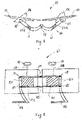
- In 1 is a simplified schematic top view of a device 10 according to the invention, with which two screens 21 and 22 are connected to each other.
- the screens 21 and 22 are angled towards one another in a position of use.
- FIG 2 shows a rear view of the in figure 1 device 10 according to the invention shown in a position of use with screens 21, 22 angled towards one another.
- the device 10 has a holding device 14 which has two holding elements 141 and 142 .
- the two computer screens 21 and 22 are each rotatably connected to one of the holding elements 141, 142 by means of two hinges 15 each.
- the two holding elements 141, 142 are, as in the Figures 1 and 2 shown, rotatably connected to one another by means of further hinges 15, so that the device can be folded up in a transport position.
- the screens 21 and 22 can then be brought parallel to each other.
- the device 10 also has two stands 16 for setting down the two computer screens 21, 22, which are rotatably connected to the respective holding elements 141, 142.
- Another embodiment of the invention which is not shown here, also provides that the uprights 16 are rigidly connected to the respective holding elements 141, 142.
- a carrying device 18, 181 which consists of two handles 18 and two carrying levers 181 connected thereto.
- the support levers 181 are firmly connected to the holding elements 141, 142 in this exemplary embodiment, it being understood that a detachable connection is also possible.
- the support levers 181 and the handles 18 are attached so that they correspond to one another, so that the handles can be brought together at a minimal distance from one another and can be easily grasped with one hand.
- the holding device 14 is designed with two holding elements 141, 142 lying opposite one another, as in FIG 2 is shown, so that between the holding elements 141, 142 in each case a receptacle for attaching and fastening a respective electrical box 122 is created.
- a docking station, a power pack, a power distribution strip, a plug strip, cables and other electrical components can be placed in the electrical box 122, which is attached to the back of the computer screens 21, 22 in each case.
- the electrical boxes 122 are designed as closed modules that can be easily replaced.
- FIG. 3 a top view of the device 10 according to the invention is shown according to a second embodiment of the invention.
- two screens 21, 22 are connected to the device 10 with each other.
- This figure shows the screens 21, 22 in a position of use so that they are angled towards one another.
- a keyboard 30 and a mouse 40 are arranged in a usage position in front of the screens 21, 22 and are therefore not connected to the device 10.
- FIG 4 shows a plan view of the device according to FIG 3 with the screens 21, 22 arranged in a straight line.
- the device 10 according to the invention also has a holding device 14 which comprises two holding elements 141 and 142.
- the holding elements 141 and 142 are rotatably connected to one another by means of a hinge 15 .
- a rear view of the device according to FIG 4 is in 12 shown.
- the hinge 15 is in figure 5 , which shows a rear view of the device 10 according to the second embodiment in a transport position, and also in FIG figure 6 10, which shows a front view of the device 10 according to the second embodiment in the transport position.
- a computer 70 and a docking station 80 on the back of each screen 21, 22 are arranged.
- the other components, such as keyboard 30, mouse 40 and a contacting device 60 are arranged at the front.
- the mouse is 40, as in figure 6 shown mounted in a recess 140 provided in the holding member 141 .
- the keyboard 30 is fitted in a recess 1230 provided in the two holding elements 141 and 142 .
- the handle 18 is firmly connected to a carrier 12 and extends over the screens 21, 22 in the transport position, so that the entire assembly is easily transportable.
- the carrier 12 is fixedly connected at its opposite side to a stand 16, such as that figure 5 can be seen.
- handles 15 it is quite possible and easily realizable to connect the handles 15 to the respective carrier 12, for example by means of a hinge, so that the handles 15 protrude over the screens 21, 22 only in the transport position and are easy to grasp. In a working position, the handles 15 are then tilted so that they are not visually disturbing to the user.
- figure 9 shows a side view of the device 10 according to the second embodiment in a transport position with the screens and facing inwards figure 10 shows a side view according to FIG 9 from the opposite side.
- the two screens 21, 22, folded and placed in the transport position are arranged with their respective displays facing one another, like this that there is a minimum protective distance between the displays and thus they are protected on the one hand and on the other hand the whole arrangement is very compact.
- a top view of the device 10 according to FIG figure 9 is in figure 11 shown.
- the Figures 7 and 8 show in this respect a third embodiment of the device according to the invention in a transport position with screens 21, 22 pointing outwards.
- the further computer peripheral devices such as the keyboard 30 and the contacting device 60, which are 7 are shown between the two computer screens 21, 22.
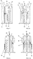
- FIG 12 shows a side view of a device 10 with a screen 21 attached thereto in a position of use.
- a carrying device has a carrying lever 181 with a holding element 18 connected thereto.
- the support lever 181 is pivoted downwards, so that the holding element 18 is also directed downwards.
- figure 14 shows a side view of the device 10 according to the invention with the attached screen 21, which is lowered and in preparation for a transport position.
- figure 15 shows the device according to FIG figure 14 with partially pivoted support lever 181.
- FIG figure 16 shows the device according to FIG figure 15 with the support lever 181 pivoted completely upwards in the transport position with an engaged latching device which has a latching element 17 .
- the locking element 17 is in a locking position, so that the device 10 is locked and ready for transport or for parking.
- figure 17 shows a side view of the device 10 with the screen 22 lowered in preparation for a transport position.
- figure 18 shows the device according to FIG figure 17 with partially pivoted support lever 181 and
- figure 19 shows the device 10 according to FIG figure 17 with the support lever 181 pivoted fully upwards in the transport position with the latching device engaged.
- figure 20 shows a rear view of the device according to the invention according to a third embodiment in the position of use with a representation of the pivoting and Possibilities of shifting the screens 21 and 22.
- the two screens 21 and 22 can be shifted towards and away from one another both horizontally and vertically with the device 10 according to the invention.
Landscapes
- Engineering & Computer Science (AREA)
- General Engineering & Computer Science (AREA)
- Theoretical Computer Science (AREA)
- Mechanical Engineering (AREA)
- Computer Hardware Design (AREA)
- Human Computer Interaction (AREA)
- Physics & Mathematics (AREA)
- General Physics & Mathematics (AREA)
- Casings For Electric Apparatus (AREA)
Applications Claiming Priority (1)
| Application Number | Priority Date | Filing Date | Title |
|---|---|---|---|
| DE102020131526.0A DE102020131526A1 (de) | 2020-11-27 | 2020-11-27 | Vorrichtung zum Verbinden von elektronischen Geräten |
Publications (1)
| Publication Number | Publication Date |
|---|---|
| EP4006693A1 true EP4006693A1 (fr) | 2022-06-01 |
Family
ID=79024993
Family Applications (1)
| Application Number | Title | Priority Date | Filing Date |
|---|---|---|---|
| EP21210778.3A Withdrawn EP4006693A1 (fr) | 2020-11-27 | 2021-11-26 | Dispositif de connexion des appareils électroniques |
Country Status (2)
| Country | Link |
|---|---|
| EP (1) | EP4006693A1 (fr) |
| DE (1) | DE102020131526A1 (fr) |
Citations (3)
| Publication number | Priority date | Publication date | Assignee | Title |
|---|---|---|---|---|
| US20040195471A1 (en) | 2003-01-09 | 2004-10-07 | Sachen Richard John | Dual flat panel monitor stand |
| US20150060615A1 (en) * | 2013-08-29 | 2015-03-05 | Chien-Chen Liu | Holder Assembly |
| US20180216776A1 (en) | 2017-01-30 | 2018-08-02 | Bloomberg Finance L.P. | Folding monitor stand |
Family Cites Families (5)
| Publication number | Priority date | Publication date | Assignee | Title |
|---|---|---|---|---|
| DE4223354A1 (de) | 1992-07-16 | 1994-01-20 | Georg Naujoks | An einen handelsüblichen Computer mit Monitor-Treiberkarte anschließbares Daten-Ausgabegerät |
| DE19616029A1 (de) | 1996-04-23 | 1997-11-06 | Ingo Prof Demske | Anordnung zur interaktiven Informationsübermittlung |
| EP1190296B1 (fr) | 1999-05-28 | 2005-01-26 | JOPET GmbH & Co.KG | Dispositif de presentation |
| US20070139874A1 (en) | 2005-12-15 | 2007-06-21 | Eiichi Tanaka | Detachable handle for notebook computers |
| DE102009043835B3 (de) | 2009-08-23 | 2010-12-16 | Tech-Linx Sdn. Bhd. | Tragbarer Computer |
-
2020
- 2020-11-27 DE DE102020131526.0A patent/DE102020131526A1/de active Pending
-
2021
- 2021-11-26 EP EP21210778.3A patent/EP4006693A1/fr not_active Withdrawn
Patent Citations (3)
| Publication number | Priority date | Publication date | Assignee | Title |
|---|---|---|---|---|
| US20040195471A1 (en) | 2003-01-09 | 2004-10-07 | Sachen Richard John | Dual flat panel monitor stand |
| US20150060615A1 (en) * | 2013-08-29 | 2015-03-05 | Chien-Chen Liu | Holder Assembly |
| US20180216776A1 (en) | 2017-01-30 | 2018-08-02 | Bloomberg Finance L.P. | Folding monitor stand |
Also Published As
| Publication number | Publication date |
|---|---|
| DE102020131526A1 (de) | 2022-06-02 |
Similar Documents
| Publication | Publication Date | Title |
|---|---|---|
| DE10150013A1 (de) | Bewegliche Tischklappe | |
| EP2028580B1 (fr) | Dispositif de contrôle pour une machine-outil | |
| DE202008004809U1 (de) | Höhenverstellbarer Geräteständer | |
| DE9103509U1 (de) | Computer-Arbeitsplatz | |
| DE112021003365T5 (de) | Armbaugruppe | |
| DE102004033911B3 (de) | Vorrichtung zur Aufnahme eines tragbaren Computers (Notebooks, Laptops) | |
| EP4006693A1 (fr) | Dispositif de connexion des appareils électroniques | |
| EP0834268A2 (fr) | Table mobile et utilisation de cette table mobile | |
| DE29502406U1 (de) | Schrank für einen insbesondere medizinischen Arbeitsbereich | |
| EP0172206B1 (fr) | Table de travail pour micro-ordinateur | |
| EP0794715B1 (fr) | Module de visualisation pour poste de travail | |
| DE102008027386B4 (de) | Tisch, insbesondere Schultisch, sowie Computertisch | |
| EP2215927B1 (fr) | Table | |
| EP4340678B1 (fr) | Poste de travail avec écran | |
| DE102014108206A1 (de) | Werkbank | |
| DE29618083U1 (de) | EDV-System-Koffer | |
| DE20012879U1 (de) | Computer-Arbeitsplatz | |
| DE10041214B4 (de) | Tragbare Vorrichtung für Geräte eines mobilen Büros | |
| DE202009010646U1 (de) | Tischmöbel | |
| DE102019000273B4 (de) | Arbeitstisch | |
| EP3144203A1 (fr) | Chariot de transport pour ustensiles de nettoyage | |
| EP0227957A1 (fr) | Dispositif pour supporter un écran, ou équivalents, et un clavier | |
| DE29703836U1 (de) | Tisch, insbesondere Schreibtisch | |
| DE20216239U1 (de) | Tischmöbel mit höhenverstellbarem Gestell | |
| DE102023115502A1 (de) | Werkstattwagen und Nutzung eines solchen Wagens |
Legal Events
| Date | Code | Title | Description |
|---|---|---|---|
| PUAI | Public reference made under article 153(3) epc to a published international application that has entered the european phase |
Free format text: ORIGINAL CODE: 0009012 |
|
| STAA | Information on the status of an ep patent application or granted ep patent |
Free format text: STATUS: THE APPLICATION HAS BEEN PUBLISHED |
|
| AK | Designated contracting states |
Kind code of ref document: A1 Designated state(s): AL AT BE BG CH CY CZ DE DK EE ES FI FR GB GR HR HU IE IS IT LI LT LU LV MC MK MT NL NO PL PT RO RS SE SI SK SM TR |
|
| STAA | Information on the status of an ep patent application or granted ep patent |
Free format text: STATUS: THE APPLICATION IS DEEMED TO BE WITHDRAWN |
|
| 18D | Application deemed to be withdrawn |
Effective date: 20221202 |