EP4006748A1 - Tonabstimmung - Google Patents
Tonabstimmung Download PDFInfo
- Publication number
- EP4006748A1 EP4006748A1 EP22151836.8A EP22151836A EP4006748A1 EP 4006748 A1 EP4006748 A1 EP 4006748A1 EP 22151836 A EP22151836 A EP 22151836A EP 4006748 A1 EP4006748 A1 EP 4006748A1
- Authority
- EP
- European Patent Office
- Prior art keywords
- audio
- fingerprint
- matching
- audio samples
- filters
- Prior art date
- Legal status (The legal status is an assumption and is not a legal conclusion. Google has not performed a legal analysis and makes no representation as to the accuracy of the status listed.)
- Granted
Links
Images


Classifications
-
- G—PHYSICS
- G10—MUSICAL INSTRUMENTS; ACOUSTICS
- G10L—SPEECH ANALYSIS TECHNIQUES OR SPEECH SYNTHESIS; SPEECH RECOGNITION; SPEECH OR VOICE PROCESSING TECHNIQUES; SPEECH OR AUDIO CODING OR DECODING
- G10L19/00—Speech or audio signals analysis-synthesis techniques for redundancy reduction, e.g. in vocoders; Coding or decoding of speech or audio signals, using source filter models or psychoacoustic analysis
- G10L19/018—Audio watermarking, i.e. embedding inaudible data in the audio signal
-
- G—PHYSICS
- G06—COMPUTING OR CALCULATING; COUNTING
- G06F—ELECTRIC DIGITAL DATA PROCESSING
- G06F16/00—Information retrieval; Database structures therefor; File system structures therefor
- G06F16/60—Information retrieval; Database structures therefor; File system structures therefor of audio data
- G06F16/63—Querying
- G06F16/632—Query formulation
-
- G—PHYSICS
- G06—COMPUTING OR CALCULATING; COUNTING
- G06F—ELECTRIC DIGITAL DATA PROCESSING
- G06F16/00—Information retrieval; Database structures therefor; File system structures therefor
- G06F16/60—Information retrieval; Database structures therefor; File system structures therefor of audio data
- G06F16/63—Querying
- G06F16/635—Filtering based on additional data, e.g. user or group profiles
-
- G—PHYSICS
- G06—COMPUTING OR CALCULATING; COUNTING
- G06F—ELECTRIC DIGITAL DATA PROCESSING
- G06F16/00—Information retrieval; Database structures therefor; File system structures therefor
- G06F16/60—Information retrieval; Database structures therefor; File system structures therefor of audio data
- G06F16/63—Querying
- G06F16/638—Presentation of query results
-
- G—PHYSICS
- G06—COMPUTING OR CALCULATING; COUNTING
- G06F—ELECTRIC DIGITAL DATA PROCESSING
- G06F16/00—Information retrieval; Database structures therefor; File system structures therefor
- G06F16/60—Information retrieval; Database structures therefor; File system structures therefor of audio data
- G06F16/68—Retrieval characterised by using metadata, e.g. metadata not derived from the content or metadata generated manually
- G06F16/683—Retrieval characterised by using metadata, e.g. metadata not derived from the content or metadata generated manually using metadata automatically derived from the content
-
- G—PHYSICS
- G10—MUSICAL INSTRUMENTS; ACOUSTICS
- G10L—SPEECH ANALYSIS TECHNIQUES OR SPEECH SYNTHESIS; SPEECH RECOGNITION; SPEECH OR VOICE PROCESSING TECHNIQUES; SPEECH OR AUDIO CODING OR DECODING
- G10L25/00—Speech or voice analysis techniques not restricted to a single one of groups G10L15/00 - G10L21/00
- G10L25/48—Speech or voice analysis techniques not restricted to a single one of groups G10L15/00 - G10L21/00 specially adapted for particular use
- G10L25/51—Speech or voice analysis techniques not restricted to a single one of groups G10L15/00 - G10L21/00 specially adapted for particular use for comparison or discrimination
- G10L25/54—Speech or voice analysis techniques not restricted to a single one of groups G10L15/00 - G10L21/00 specially adapted for particular use for comparison or discrimination for retrieval
Definitions
- the present invention relates to methods and apparatus for audio matching.
- the invention has particular, but not exclusive relevance to audio matching systems in which a portable user device, such as a computer tablet or a cellular telephone, can capture sounds which can then be identified by a matching process.
- Passive audio recognition techniques do not require the hiding of a watermark - so in theory can be used to recognise any audio sample.
- passive audio recognition techniques have the disadvantage that they require a more demanding comparison between sampled audio and a large database of audio samples.
- the captured audio is likely to be relatively noisy compared to the original audio and this can easily lead to errors in the recognition results.
- One common technique used to passively match audio is to create an acoustic 'fingerprint' of the captured sound and then to compare this fingerprint with corresponding fingerprints of audio signals in the database. The fingerprint tries to capture the important acoustic features of the audio signal which helps to reduce the burden of matching the audio sample with the audio in the database.
- the present invention provides an audio matching system comprising: means (which may be a microphone, an antenna or a central processing unit) for capturing an audio signal; means (which may be a hardware circuit or a software module being run by one or more central processing units) for processing the captured audio signal to generate a fine query acoustic fingerprint representative of the captured audio signal; means (which may be a hardware circuit or a software module being run by one or more central processing units) for generating a coarse query acoustic fingerprint representative of the captured audio signal; an audio database comprising a plurality of database entries, each entry being associated with audio content, and each entry comprising: i) a fine database acoustic fingerprint representative of the associated audio content; and ii) information relating to the associated audio content; means (which may be a hardware circuit or a software module being run by one or more central processing units) for matching the coarse query acoustic fingerprint with coarse database acoustic fingerprints associated with said plurality of database entries to identify a subset of
- Each database entry may comprise the associated coarse database acoustic fingerprint or the system may further comprise means (which may be a hardware circuit or a software module being run by one or more central processing units) for generating the coarse database acoustic fingerprint associated with a database entry.
- the means for generating the coarse query acoustic fingerprint is configured to generate the coarse query acoustic fingerprint from the fine query acoustic fingerprint. This is similarly true for embodiments, in which the coarse database acoustic fingerprint is generated from the associated fine acoustic fingerprint.
- the coarse query or database acoustic fingerprint may be generated by applying a set of filters to the fine query or database acoustic fingerprint.
- the fine query acoustic fingerprint comprises an array of values and the coarse query or database acoustic fingerprint is generated by applying a filter from the set of filters to a portion of the array of values to generate a value of the coarse query or database acoustic fingerprint.
- Each filter normally comprises a plurality of filter coefficients and the coarse query or database acoustic fingerprint is generated by applying the filter to the portion by weighting each value of the portion with a respective filter coefficient and by combining the weighted values.
- Each filter may be applied to a plurality of portions of the array to generate a corresponding plurality of values of the coarse query or database fingerprint.
- a row or column of the coarse query or database acoustic fingerprint may be generated in response to applying each filter to the fine query acoustic fingerprint.
- the fine acoustic fingerprints have a greater bit rate than the coarse acoustic fingerprints.
- the audio matching system may further comprise means (which may be a hardware circuit or a software module being run by one or more central processing units) for generating a spectrogram of the captured audio signal and wherein the means for generating the fine query acoustic fingerprint may generate the fine acoustic fingerprint from the spectrogram.
- the spectrogram may be generated in numerous ways including performing a frequency transform such as a Fast Fourier Transform (FFT) or a Discrete Fourier Transform (DFT) or by taking a wavelet transform of the captured audio signal.
- FFT Fast Fourier Transform
- DFT Discrete Fourier Transform
- the means for generating the fine query acoustic fingerprint is configured to apply a set of filters to the spectrogram to generate the fine query fingerprint.
- the means for generating the fine query acoustic fingerprint may apply a set of filters to the spectrogram that is different to the set of filters applied by the means for generating the coarse query acoustic fingerprint.
- the means for generating the fine query acoustic fingerprint may apply a filter from the set of filters to a portion of the spectrogram to generate a value of the fine query acoustic fingerprint.
- Each filter typically comprises a plurality of filter coefficients and the means for generating the fine query acoustic fingerprint applies the filter to the portion of the spectrogram by weighting each value of the portion with a respective filter coefficient and by combining the weighted values to generate the value of the fine query acoustic fingerprint.
- Each filter from the set of filters is typically applied to a plurality of portions of the spectrogram to generate a corresponding plurality of values of the fine query acoustic fingerprint.
- a row or column of the fine query acoustic fingerprint may be generated in response to applying each filter to the spectrogram.
- the means for generating the fine query acoustic fingerprint is configured to order the rows or columns of the fine query acoustic fingerprint that are generated by applying the set of filters to the spectrogram so that similar rows or columns are adjacent to each other.
- the means for generating the fine query acoustic fingerprint may order the rows or columns of the fine query acoustic fingerprint in order to increase coherence between neighbouring rows or columns of the fine query acoustic fingerprint.
- Each filter may have an associated offset that defines portions of the spectrogram or portions of the fine query acoustic fingerprint to which the filter is applied.
- the present invention also provides an audio matching method performed by one or more processors, the method comprising: capturing an audio signal; processing the captured audio signal to generate a fine query acoustic fingerprint representative of the captured audio signal; generating a coarse query acoustic fingerprint representative of the captured audio signal; matching the coarse query acoustic fingerprint with coarse database acoustic fingerprints of a plurality of database entries to identify a subset of possibly matching database entries; matching the fine query acoustic fingerprint with fine database acoustic fingerprints of the database entries in said subset of possibly matching database entries to identify a matching database entry; and outputting a matching response comprising information relating to the identified matching database entry.
- the present invention also provides an audio matching system comprising: an audio database comprising a plurality of database entries, each entry being associated with audio content, and each entry: i) comprising a first database acoustic fingerprint representative of the associated audio content and having a first bit rate; ii) having an associated second database acoustic fingerprint representative of the associated audio content and having a second bit rate that is lower than the first bit rate; and iii) comprising information relating to the associated audio content; and one or more processors (which may be central processing units) configured to: capture an audio signal; process the captured audio signal to generate a first query acoustic fingerprint representative of the captured audio signal and having said first bit rate; generate a second query acoustic fingerprint representative of the captured audio signal and having said second bit rate; match the second query acoustic fingerprint with the second database acoustic fingerprints associated with said plurality of database entries to identify a subset of possibly matching database entries; match the first query acoustic fingerprint with the first database acou
- Each database entry may comprise the associated second database acoustic fingerprint or the one or more processors may be configured to generate the second database acoustic fingerprint associated with a database entry either from a spectrogram of the associated audio signal or from the first database acoustic fingerprint associated with that database entry.
- the present invention also provides an audio matching system comprising: a user device, an audio matching server and an audio database comprising a plurality of database entries, each entry being associated with audio content, and each entry: i) comprising a first database acoustic fingerprint representative of the associated audio content and having a first bit rate; ii) having an associated second database acoustic fingerprint representative of the associated audio content and having a second bit rate that is lower than the first bit rate; and iii) comprising information relating to the associated audio content; wherein the user device has one or more processors (which may be central processing units) configured to: capture an audio signal; process the captured audio signal to generate a first query acoustic fingerprint representative of the captured audio signal and having said first bit rate; wherein the audio matching server has one or more processors (which may be central processing units); wherein the one or more processors of the user device or the one or more processors of the audio matching server is configured to generate a second query acoustic fingerprint representative of the captured audio signal and having said
- the present invention also provides a user device for use in an audio matching system, the user device comprising: means (which may be a hardware circuit or a software module being run by one or more central processing units) for capturing an audio signal; means (which may be a hardware circuit or a software module being run by one or more central processing units) for processing the captured audio signal to generate a fine query acoustic fingerprint representative of the captured audio signal; means (which may be a hardware circuit or a software module being run by one or more central processing units) for generating a coarse query acoustic fingerprint representative of the captured audio signal; means (which may be a hardware circuit or a software module being run by one or more central processing units) for outputting the coarse query acoustic fingerprint and the fine query acoustic fingerprint to an audio matching server; and means (which may be a hardware circuit or a software module being run by one or more central processing units) for receiving a matching response comprising information relating to the captured audio.
- the present invention also provides an audio matching server for use in an audio matching system, the audio matching server comprising: means (which may be a hardware circuit or a software module being run by one or more central processing units) for receiving a fine query acoustic fingerprint representative of a captured audio signal; means (which may be a hardware circuit or a software module being run by one or more central processing units) for receiving or generating a coarse query acoustic fingerprint representative of the captured audio signal; means (which may be a hardware circuit or a software module being run by one or more central processing units) for matching the coarse query acoustic fingerprint with coarse database acoustic fingerprints associated with a plurality of database entries to identify a subset of possibly matching database entries; means (which may be a hardware circuit or a software module being run by one or more central processing units) for matching the fine query acoustic fingerprint with fine database acoustic fingerprints of the database entries in said subset of possibly matching database entries to identify a matching database entry; and means (which may be a
- the present invention also provides a method of identifying an optimised set of filters for use in generating an acoustic fingerprint, the method comprising: i) providing one or more databases comprising a plurality of audio samples including N M matched pairs of audio samples and N N non-matched pairs of audio samples, each matched pair of audio samples comprising an original audio sample and a distorted version of a same original audio signal and each non-matched pair of audio samples comprising an original audio sample and a version of a different original audio signal; ii) determining a spectrogram for each audio sample in the one or more databases; iii) applying each of N f candidate filters to each spectrogram and binarising a result to generate a plurality of vectors of binary bits, each vector of binary bits being associated with one candidate filter and one audio sample; iv) comparing bits in the vectors associated with a selected matched pair of audio samples for a current filter to determine bit error rate information for the current filter and the selected matched pair of audio samples; v) repeating
- Determining the optimised set of filters may use the determined matching and non-matching mean and variance information for each candidate filter to minimise the chance of false positives or to minimise the chance of false negatives or some combination of both.
- the method may further comprise determining covariance information for each of a plurality of pairs of filters using the determined mean and variance information; and wherein said determining said optimised set of filters for use in generating an acoustic fingerprint uses the determined matching and non-matching mean and variance information and the covariance information.
- determining the optimised set of filters includes using a dynamic programming optimisation technique to identify the optimised set of filters.
- the present invention also provides an apparatus for identifying an optimised set of filters for use in generating an acoustic fingerprint, the apparatus comprising: one or more databases comprising a plurality of audio samples including N M matched pairs of audio samples and N N non-matched pairs of audio samples, each matched pair of audio samples comprising an original audio sample and a distorted version of a same original audio signal and each non-matched pair of audio samples comprising an original audio sample and a version of a different original audio signal; and one or more processors (which may be central processing units) configured to: i) determine a spectrogram for each audio sample in the one or more databases; ii) apply each of N f candidate filters to each spectrogram and binarising a result to generate a plurality of vectors of binary bits, each vector of binary bits being associated with one candidate filter and one audio sample; iii) compare bits in the vectors associated with a selected matched pair of audio samples for a current filter to determine bit error rate information for the current filter and the selected matched pair
- the invention also provides a user device for use in an audio matching system, the user device comprising: means (which may be a hardware circuit or a software module being run by one or more central processing units) for capturing an audio signal; means (which may be a hardware circuit or a software module being run by one or more central processing units) for processing the captured audio signal to generate a query acoustic fingerprint representative of the captured audio signal using a set of optimised filters determined using the above described methods; means (which may be a hardware circuit or a software module being run by one or more central processing units) for outputting the query acoustic fingerprint to an audio matching server; and means (which may be a hardware circuit or a software module being run by one or more central processing units) for receiving a matching response comprising information relating to the captured audio.
- the invention also provides a computer program product comprising computer implementable instructions for causing a programmable computer device to perform all the method steps discussed above or to become configured as the above described apparatus.
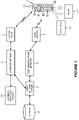
- FIG. 1 is a block diagram illustrating the main components of an audio matching system embodying the present invention.
- the system relies on a user having a user device 1 (in this case a cellular telephone) that can capture sound 2 generated by a sound source 3 (such as a television 3-1, a radio 3-2, or a live performance etc.).
- the user device 1 processes the captured sound 2 and generates an acoustic fingerprint that represents the captured sound.
- these acoustic fingerprints will simply be referred to as fingerprints for ease of explanation. The way in which the fingerprint is generated will be described in more detail later.
- the user device 1 transmits the generated fingerprint as a query to a remote audio matching server 5 either via the base station 7 and telecommunications network 9 or via an access point 11 and computer network 13 (e.g. the internet).
- the audio matching server 5 processes the query fingerprint to generate a coarse query fingerprint which the server then uses to search for possibly matching entries within the database 15.
- the coarse fingerprint has a lower resolution or bit rate compared with the received query fingerprint. This first search using the coarse query fingerprint will identify a subset of possibly matching entries within the database 15.
- the audio matching server 5 compares the higher resolution (or "fine") query fingerprint received from the user device 1 with the subset of entries identified by the first search to identify the database entry that is most similar to the fine query fingerprint.
- the audio matching server 5 then outputs information retrieved from the matching entry in the database 15, to the user device 1.
- Various different information may be returned, such as identification information of the audio captured by the user device 1; artist information; related content (such as other content from the same artist); and even computer links to content stored on other servers connected to the computer network 13.
- the user device 1 then outputs the returned information to the user, for example via the display 17 of the user device.
- An example is where the audio matching process identifies the advertisement or TV programme a viewer is watching and then presents relevant content to the user.
- the information retrieved from the database 15 may be provided to a third party instead of or in addition to the user device 1. This may be useful in audience surveying applications, where the purpose of the audio matching process is to identify the television or radio programme that the user is listening to or watching; which information is then sent to a third party audience surveying server 19 via the computer network 13.
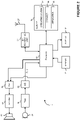
- FIG. 2 is a block diagram illustrating the main components of the user's cellular telephone 1 used in this embodiment.
- the cellular telephone 1 includes a microphone 23 for receiving the acoustic signals 2 (such as the sound output by the television 3-1 or the radio 3-2) and for converting these acoustic signals into electrical equivalent signals.
- the electrical signals from the microphone 23 are then filtered by the filter 51 to remove unwanted frequencies typically those outside the frequency band of 200 Hz to 20 kHz.
- the filtered audio is then digitised by an analogue to digital converter 53, which samples the filtered audio typically at a sampling frequency of 24 or 48 kHz and represents each sample by a 16 bit digital value.
- the stream of digitised audio (D(t)) is then input to a processor 63 (which may comprise one or more central processing units).
- the processor 63 compresses the received audio and then passes it to an RF processing unit 57 which modulates the compressed audio data onto one or more RF carrier signals for transmission to the base station 7 via the antenna 27.
- compressed audio signals received via the antenna 27 are fed to the RF processing unit 57, which demodulates the received RF signals to recover the compressed audio data from the RF carrier signal(s), which is then passed to the processor 63 for decompression.
- the regenerated audio samples are then output to the loudspeaker 25 via the digital to analogue converter 59 and the amplifier 61.
- the processor 63 is controlled by software stored in memory 65.
- the software includes operating system software 67 (for controlling the general operation of the cellular telephone 1), a browser 68 for accessing the internet and application software 69 for providing additional functionality to the cellular telephone 1.
- the application software 69 is part of the audio matching system and causes the cellular telephone to capture the sound 2 for recognition purposes.
- the application software 69 also generates the above described fine fingerprint which is sent to the audio matching server 5 as a query.
- the application software 69 also responds to the data received back from the audio matching server 5 - for example by outputting information to the user on the display 17; or by retrieving information from another server using a link returned from the audio matching server 5.
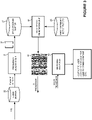
- FIG. 3 is a block diagram illustrating the main processing functionality of the application software 69 used in this embodiment.
- the application software 69 receives as an input, the sampled audio signal (D(t)) from the A/D converter 53. This sampled audio is stored into an audio buffer 32.
- the audio samples in the audio buffer 32 are processed by a frequency analysis unit 34 which processes the audio samples in the audio buffer 32 to generate a spectrogram 35 of the audio signal (D(t)) which is stored in the spectrogram buffer 37.
- the spectrogram 35 is a time and frequency representation of the audio signal (D(t)) and illustrates the way in which the frequency content of the audio signal (D(t)) changes with time over the duration of the audio signal.
- the frequency analysis unit 34 builds the spectrogram 35 by extracting frames of audio samples from the incoming audio signal D(t) and determining the frequency content of the audio signal in each frame (i.e. what frequencies are present and at what amplitudes).
- the input audio signal D(t) is divided into overlapping frames 39 to allow a "short time" spectral analysis of the audio samples in each frame - as is standard in the field of audio processing.
- a frame 39 of samples is extracted once every 10 to 20 milliseconds and the frames 39 may be overlapping (as illustrated) or non-overlapping.
- the frequency analysis unit 34 operates in parallel with the writing of the incoming samples into the audio buffer 32. In other words, the frequency analysis unit 34 can start its analysis as soon as the first frame (f 1 ) of audio samples is written into the audio buffer 32 and stops after a predefined time or at the end of the audio clip that is captured by the microphone 23.
- a windowing function (such as a Hamming window) is typically used to extract the frames 39 of samples from the incoming audio signal (D(t)) - to reduce distortions introduced by the extraction.
- the frequency analysis unit 34 performs a frequency analysis process on the audio samples to determine the frequency content within a defined frequency band of interest, which will typically be a portion of the passband of the filter 51. In this embodiment, this frequency band of interest is limited to the band 475 Hz to 2.52 kHz. Other frequency bands may of course be used.
- the frequency analysis process performed by the frequency analysis unit 34 can be done in a number of different ways - such as by using a Fast Fourier Transform (FFT) or a Discrete Cosine Transform (DCT) or by using wavelet transforms or even by using an array of filter banks. In the preferred embodiment wavelet transforms are used.
- FFT Fast Fourier Transform
- DCT Discrete Cosine Transform
- wavelet transforms are used.
- This frequency analysis will generate, for each frame 39 of audio samples, a vector of numbers - representing the frequency content (amplitude) in each of a number (K) of frequency sub-bands within the defined frequency band of interest (e.g. 475 Hz to 2.52 kHz).
- the frequency analysis of the first frame f 1 results in the generation of the vector of numbers f 1 1 , f 1 2 , f 1 3 ... f 1 K ; where the number f 1 1 represents the frequency content in the first frequency sub-band of the audio samples in the first frame, f 1 2 represents the frequency content in the second frequency sub-band of the audio samples in the first frame, f 1 3 represents the frequency content in the third frequency sub-band of the audio samples in the first frame, etc.
- the number of sub-bands considered i.e. the value of K) depends on the available processing power of the processor 63 and the frequency resolution required to extract a meaningful (distinguishable) fingerprint.
- the frequency analysis of the second frame f 2 results in the generation of the vector of numbers f 2 1 , f 2 2 , f 2 3 ... f 2 K ; where the number f 2 1 represents the frequency content in the first sub-band of the audio samples in the second frame, f 2 2 represents the frequency content in the second sub-band of the audio samples in the second frame, f 2 3 represents the frequency content in the third sub-band of the audio samples in the second frame, etc.
- the spectrogram 35 is formed by concatenating the vectors generated from the series of frames 39 extracted from the audio signal D(t).
- the spectrogram thus generated is effectively a K x L matrix of values representing the audio clip.
- the rows of the matrix represent the different frequency sub-bands and the different columns represent different points of time within the audio clip.
- the individual value in the spectrogram at location (i, j) corresponds to the amplitude of the frequency component in sub-band i at time j.
- the matrix could be written in the transpose - with the columns representing the frequency sub-bands and the rows representing the time points. Therefore, references to rows and columns in this document are interchangeable.
- a fingerprint generation unit 41 processes the spectrogram 35 to generate a fingerprint 43.
- the fingerprint generation unit 41 generates the fingerprint 43 by applying a first optimised set 45 of filters to the spectrogram 35 and binarising the result.
- a first optimised set 45 of filters There are many different possible filter combinations that can be used to generate a fingerprint and the first optimised set 45 of filters has been found through an optimisation process. The way in which this optimisation process is performed will be described later. The way in which this first optimised set 45 of filters is used to generate the fingerprint 43 will now be explained in detail with reference to Figures 5a to 5f .
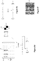
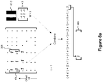
- FIG. 5a illustrates five different types of filter 47-1, 47-2, 47-3, 47-4 and 47-5 that can be applied to different parts of the spectrogram 35.
- Each filter 47 has a height (H) and a width (W) that defines the size of the filter; and an offset (O) that defines the frequency sub-bands of the spectrogram 35 to which the filter 47 will be applied.
- the coefficients of each filter 47 sum to zero.
- the filter type 47-1 can be formed from the following matrix of coefficients: ⁇ 1 1 1 ⁇ 1
- the filter type 47-2 can be formed from the following matrix of coefficients: ⁇ 1 2 ⁇ 1
- Figure 5b illustrates the way in which a filter 47 (in this case filter 47-1) is applied to the spectrogram 35 at a given offset from the base of the spectrogram.
- the filter 47 is stepped across the time axis of the spectrogram 35 and at each step the coefficients of the filter 47 are used to perform a weighted combination of the frequency values at the relevant part of the spectrogram 35.
- the number of frequency values that are combined at each step depends on the size (W, H) of the filter 47 and how they are combined depends on the coefficients of the filter 47.
- the combined value from each step is then written into a vector of combined values that is quantised (or binarised) into "1"s and "0"s depending on whether the combined values are greater or less than zero.
- Figure 5c illustrates the application of an example filter (that is a type 47-1 filter) that is 2 by 2 in size and having an offset of 10.
- the filter 47-1 is applied to the values in the spectrogram 35 that are 10 rows up from the bottom of the spectrogram 35 (of course the offset can be defined from any point within the spectrogram 35).
- the first block 32 of amplitude values from the spectrogram 35 at the defined offset are combined by multiplying these amplitude values with the corresponding coefficients in the filter 47-1 and then adding the values together.
- the amplitude value 6 is multiplied by the filter coefficient -1; the amplitude value 4 is multiplied by the filter coefficient 1; the amplitude value 3 is multiplied by the filter coefficient 1; and the amplitude value 5 is multiplied by the filter coefficient -1.
- the resulting four numbers are added together to provide a combined result of -4.
- This value is written in to the first element of a vector 42 of combined values.
- the filter 47-1 is then stepped along one time step and combined in a similar way with the next block 34 of amplitude values from the spectrogram 35. As shown, this combination results in the value 2, which is written in to the next element of the vector 42. This process is repeated until the filter 47-1 has been stepped across the length (time axis) of the spectrogram 35 and the resulting vector 42 will thus have L elements corresponding to the temporal length of the spectrogram 35.
- the combined values in this vector 42 will be both positive and negative numbers.
- these values are quantised into binary values - for example by setting all values above 0 to the binary value "1" and setting all values below zero to the binary value "0" - as shown in Figure 5e .
- the resulting binarised vector 44 will form one row of the fingerprint 43 (shown in Figure 5f ).
- this binarisation process can be performed on each combined value as it is generated and written directly in to the binarised vector 44 - instead of generating the intermediate vector 42 first.
- the fingerprint 43 is generated by applying a first optimised set 45 of these filters 47 to the spectrogram 35. Each different filter 47 in this first set 45 will produce a different row of the final fingerprint 43.
- concatenating the different binary vectors 44 produced by applying the first set 45 of filters to the spectrogram 35 into a matrix forms the final output 2D fingerprint 43.
- the order in which the binary vectors 44 are concatenated is determined in advance and the same first set 45 of filters and ordering are used to generate corresponding fingerprints for the entries in the database 15 - so that the audio matching server 5 can compare fingerprints that have been generated in the same manner.
- the first set 45 of filters comprises thirty two different filters and so the fingerprint that is generated will be a 32 by L matrix of binary values.
- the rows and columns of the fingerprint 43 are interchangeable.
- the binary vectors 44 may be used to form the columns.
- the fingerprint will be an L by 32 matrix of binary values. As long as the same process is performed to generate the fingerprints for the entries in the audio database 15, the orientation of the fingerprint 43 does not matter.
- the binary vectors 44 generated by applying the filters 47 in the optimised set 45 to the spectrogram 35 are concatenated together in an order that is defined in advance. Normally, the order does not matter - as long as the same order is applied when generating the fingerprints for the entries in the database 15. This means that in a conventional fingerprint, the 1s and 0s will be appear randomly distributed throughout the fingerprint - such as for the example fingerprint 43-1 shown in Figure 6 . However, in this embodiment, the ordering is chosen in a specific way - in particular in a way that maximises (or at least increases) the likelihood that adjacent binary vectors 44 (i.e. adjacent rows or columns) in the fingerprint 43 will be similar to each other.
- this specific ordering is determined during a training stage in which fingerprints are generated for a large collection of audio samples and the ordering is found that maximises the likelihood of adjacent rows/columns in the fingerprint 43 being similar.
- This specific ordering is defined within the application software 69 and controls the way in which the fingerprint generation unit 41 concatenates the binary vectors 44 to form the fingerprint 43.
- Figure 6 also shows a second example fingerprint 43-2 that is generated using the specific ordering discussed above. As can be seen, the fingerprint 43-2 is much less random in appearance that the fingerprint 43-1 as many more adjacent bits in the fingerprint 43-2 have the same value and thus clump together to define larger islands of the same binary value. As will be explained later, this is important for the remote audio server 5 to be able to generate a coarse fingerprint from the fingerprint 43 that will reduce the processing burden to find a matching entry in the database 15.
- the application software 69 passes the fingerprint 43 to the processor 63 for transmission to the audio matching server 5.
- the application software 69 will have stored therein address information for the audio matching server 5 so that it can send the fingerprint to the audio matching server 5; either via the telecommunications network 9 or via the computer network 13.
- the application software 69 will pass this address information and the generated fingerprint 43 to the processor 63 requesting that the fingerprint 43 is sent to the remote audio matching server 5.
- the processor 63 will then send the fingerprint 43 to the audio matching server 5 and awaits a response message.
- the processor 63 When the matching response message 46 is returned from the audio matching server 5 (either via the telecommunications network 9 or via the computer network 13), the processor 63 will receive and pass the matching response message 46 back to the application software 69.
- the application software 69 then takes an appropriate action based on the contents of the matching response message 46. For example, if the matching response message 46 simply provides details of the captured audio - such as the name of the song, the artist etc. then the application software 69 may output this information to the user such as via the display 17 or the loudspeaker 25. If the matching response message 46 includes a link for further information or content relating to the captured audio, then the application software 69 may prompt the user whether the user wishes to retrieve the information or content from the link provided.
- the application software 69 may retrieve the information or content from the link itself or it may call upon the browser software 68 to retrieve the information or content (which retrieved information or content is then output to the user, for example on the display 17). If the application software 69 forms part of an audience surveying application, then the application software 69 may simply collate the information about the audio that has been captured (such as the TV channel and programme being watched) and then send this to the remote audience surveying server 19 together with an identifier of the user that owns the phone (which may just be an identifier of the phone 1). If the matching response message 46 is a "nil" report - indicating that no matches have been found then the application software 69 may output this information to the user.
- FIG. 7 is a block diagram of the main components of the audio matching server 5 used in this embodiment.
- the audio matching server 5 includes a processor (which may be one or more central processing units) 201 that communicates with the user device 1 via a network interface 205 and the telecommunications network 9 or the computer network 13.
- the processor 201 also communicates with the database 1543 via a database interface 207.
- the interfaces 205 and 207 may be formed by a single physical interface, such as a LAN interface or the like.
- the processor 201 is controlled by software instructions stored in memory 209 (although in other embodiments, the processor 201 may be formed from one or more dedicated hardware processors - such as Application Specific Integrated Circuits).
- the software instructions include an operating system 211 that controls the overall operation of the audio matching server 5; a communications control module 213 that controls communications between the audio matching server 5 and the user device 1 and the database 15; a coarse fingerprint generation unit 215 that generates a coarse fingerprint from the query fingerprint 43 received from a user device 1; a coarse fingerprint matching unit 217 that matches the coarse fingerprint generated by the coarse fingerprint generation unit 215 with coarse fingerprints stored in the database 15; a fine fingerprint matching unit 219 that matches the fingerprint 43 received from the user device 1 with a fine fingerprint of a subset of the entries in the database 15 to identify a matching entry; and a matching response reporting unit 220 that reports the matching results back to the user device 1 in a matching response message 46.
- the coarse fingerprint generation unit 215 generates the coarse fingerprint using a second set
- the audio matching server 5 performs matching operations between coarse/fine fingerprints corresponding to a query received from the user device 1 and coarse/fine fingerprints stored within the database 15.
- the fingerprint 43 received from the user device 1 will be referred to the "fine query fingerprint” 43 and the coarse fingerprint that is generated from it will be referred to as the “coarse query fingerprint”.
- the fingerprints stored in the database 15 will be referred to as “coarse database fingerprints” and "fine database fingerprints”.
- the coarse fingerprint generation unit 215 generates the coarse query fingerprint from the fine query fingerprint 43 received from the user device 1. This is advantageous as it means that the user device 1 does not need to transmit, for example, the spectrogram 35 of the audio clip to the audio matching server 5 in order for the coarse query fingerprint to be generated.
- FIG 8 illustrates the process used by the coarse fingerprint generation unit 215 to generate the coarse query fingerprint.
- the process is very similar to the process used to generate the fine query fingerprint (described above with reference to Figure 5 ) except that a second (different) set 221 of optimised filters is used and in this case the filters 47 of this second set 221 are applied to the fine query fingerprint 43 rather than to the spectrogram 35. Additionally, instead of each filter 47 in this second set 221 of optimised filters being stepped over the fine query fingerprint 43 one time point at a time, several time points are skipped at each stage - in order to reduce the size of the coarse query fingerprint.
- the result is a compact (coarse) fingerprint that allows for a quicker initial search of the entries in the database 15.
- the coarse fingerprints could be made even more compact by reducing the number of filters 47 used in the second set 221 (compared with the number of filters used in the first set 45).
- the fine query fingerprint has a bit rate (or resolution) of 2000 bits per second of the captured audio signal
- the coarse query fingerprint will have a bit rate (or resolution) of 200 bits per second of the captured audio signal.
- Figure 8a shows the fine query fingerprint 43 written in matrix format and with binary "0"s being written as the value -1. This ensures that the filtering process accurately combines the different parts of the fine query fingerprint 43 that are to be combined with the filter.
- the filter 47 being applied to the fine query fingerprint 43 is a type 47-2 filter having height 2 and width 3.
- the width (temporal dimension) of the filter is usually larger than this and the value of 3 has been chosen for simplicity of illustration.
- the filter width is typically about twice the temporal decimation rate between the fine fingerprint and the coarse fingerprint. So if the coarse fingerprint data rate is 1/10 th that of the fine fingerprint, the decimation rate is 10 and the typical filter width would be 20, although each filter can have a different width.
- the filter has an offset of 8 meaning that the filter 47 is applied to the elements in the fine query fingerprint 43 that are 8 rows from the bottom.
- the size of this block 301 matches that of the filter 47 - so that each value in the block 301 has a corresponding filter coefficient with which it is multiplied - as shown.
- the multiplied values are summed to yield the value 2 - which is written in the first element of the vector 303.
- the filter 47 is moved along the time axis of the fine query fingerprint 43 - but this time skipping some of the elements in the fine query fingerprint 43.
- the filter is skipped along 10 elements (time points); meaning that the coarse query fingerprint that is generated will have 1/10 th of the temporal length of the fine query fingerprint 43.
- the vector 303 is binarised (as shown in Figure 8c ) to produce a binary vector 307. As before, this binarisation can be done at the time that each combined value is generated and then written directly into the binary vector 307 without using the vector 303 (or written directly into the coarse query fingerprint).
- the binary vector 307 that is produced will form one row (or one column) of the coarse query fingerprint.
- the same process is repeated for all the different filters 47 in the second set 221 of optimised filters and the resulting binary vectors 307 are concatenated to form the coarse query fingerprint 309 (shown in Figure 8d ).
- the audio matching server 5 can perform a proper match between the coarse query fingerprint 309 and the coarse database fingerprints.
- the coarse fingerprint generated in this way is still sufficiently distinctive to allow it to be used in an initial search of the database 15 in order to significantly reduce the number of database entries that have to be compared with the fine query fingerprint. This is because of the specific ordering that was performed to generate the fine query fingerprint. This ordering means that there are larger (information containing) bit patterns in the fine fingerprint and the information contained in these larger bit patterns survive to some extent through the process of generating the corresponding coarse fingerprints. If a more traditional (random looking) fine fingerprint (such as the fingerprint 43-1 shown in Figure 6 ) is used, then the above process of generating a coarse fingerprint from the fine fingerprint is likely to result in the loss of most of the information contained in the fine fingerprint.
- the coarse fingerprint will not be distinctive and so when it is compared against other similar coarse fingerprints, many are likely to be considered a possible match. This may defeat the purpose of generating the coarse fingerprint - as the fine query fingerprint will still have to be matched with a large number of potentially matching database entries.
- the coarse fingerprint matching unit 217 compares the coarse query fingerprint 309 with coarse database fingerprints stored in the database 15 in order to identify a subset of the database entries that may be a possible match.
- FIG 9 illustrates the general structure of the database entries 320. Each entry has an identifier - DB#1 for the first entry, DB#2 for the second entry etc. As shown in Figure 9 , there are D entries in the database 15. The value of D can be very large depending on the application. If the audio matching system is for use in a "Shazam ® " type of service, then D may be of the order of 10 to 20 million. However, if the audio matching system is part of an audience surveying system that is designed to identify the programme and channel the user is watching, then the number of entries (D) will be much lower, although the audio clips (or at least the fingerprints representing them) stored in the database 15 will be much longer. For example, a system designed to monitor television broadcasts made over the previous 30 days on 1000 TV channels will contain about 720,000 hours of content - which is equivalent in size to a Shazam ® type of system with 10 million songs.
- each entry will typically include:
- the coarse fingerprint matching unit 217 matches (i.e. compares) the coarse query fingerprint 309 with the coarse database fingerprint 325 stored in every entry 320 of the database 15; in order to identify a number of possible matching entries.
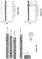
- This matching process is illustrated in Figure 10 .
- Figure 10a illustrates all the coarse database fingerprints 325.
- the coarse database fingerprint for the first database entry is labelled 325-DB#1
- the coarse database fingerprint for the second database entry is labelled 325-DB#2
- the coarse database fingerprint for the third database entry is labelled 325-DB#3 etc.
- Figure 10a illustrates that these coarse database fingerprints 325 have different temporal lengths. This is because they are typically generated from audio content having different durations.
- Figure 10a also illustrates the coarse query fingerprint 309 that is to be compared with each of these coarse database fingerprints 325.
- the coarse query fingerprint 309 has a much shorter duration than the coarse database fingerprints 325.
- the coarse query fingerprint 309 is "stepped along" the longer coarse database fingerprint 325 from start to end.
- a bit-wise comparison is performed between the bits in the coarse query fingerprint 309 and the bits in a corresponding sized portion of the coarse database fingerprint 325.
- this bit-wise comparison may be performed using an XOR type of combination of the bits from the two fingerprints - which results in a count of the number of bit differences between the two.
- This count therefore, represents the similarity between the coarse query fingerprint 309 and the current portion of the coarse database fingerprint 325.
- the coarse query fingerprint 309 is then stepped along the temporal axis and compared in a similar manner with the next portion of the coarse database fingerprint 325.
- the coarse query fingerprint 309 is stepped along one time point at a time in the coarse database fingerprint 325.
- bit-wise comparison considers the percentage of non-matching bits. Thus if there is not a match then the expected percentage of non-matching bits should be around 50% (or 0.5). If there is a match then the expected percentage of non-matching bits should be close to zero.
- Figure 10b illustrates the result of this matching process when the coarse query fingerprint 309 does not match with any portion of a coarse database fingerprint 325; and
- Figure 10c illustrates the result of this matching process when the coarse query fingerprint 309 does match with a portion of the coarse database fingerprint 325 (identified by the spike 326 in the percentage of non-matching bits).
- Whether or not the coarse query fingerprint 309 matches with a portion of the coarse database fingerprint 325 is, therefore, determined by comparing the calculated percentages with a threshold level (e.g. 10%). Thus, if the percentage of non-matching bits falls below this threshold then there is a match, if it does not then there is no match. As those skilled in the art will appreciate, other scoring metrics could be used instead.
- a threshold level e.g. 10%
- the comparison result for the comparison between the coarse query fingerprint 309 and the coarse database fingerprints 325 includes a list of database entries 320 that might match with the coarse query fingerprint 309.
- this list of possible matching entries includes entries DB#10, DB#15, DB#260 and DB#500.
- the comparison results may also optionally include timing information identifying which portion(s) within the coarse database fingerprint 325 matches with the coarse query fingerprint 309.
- the timing information may indicate that the match was found around 135 seconds from the start of the song represented by the coarse database fingerprint 325. If provided, this timing information can be used to further narrow down the comparison between the fine query fingerprint 43 and the corresponding fine database fingerprints 323.
- the comparison results obtained from the coarse fingerprint matching unit 217 are then passed to the fine fingerprint matching unit 219 which use this information to restrict the matching operation that it does between the fine query fingerprint 43 and the fine database fingerprints 323.
- the fine fingerprint matching unit 219 uses the list of possible matching entries so that the fine fingerprint comparisons are restricted to just the fine fingerprints in the database entries identified in this list of possible matching entries.
- the comparison results include timing information indicating the time within the audio content where the match was found in the coarse database fingerprint 325, then the fine fingerprint matching unit 219 uses this timing information to restrict the comparison between the fine query fingerprint 43 and the corresponding fine database fingerprint 323 to around this timing.
- the fine matching unit 219 may restrict the matching process so that the fine query fingerprint 43 is only matched with the portions of the fine database fingerprint between times 130 and 145 seconds from the start.
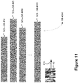
- Figure 11 illustrates the matching process that is performed between the fine query fingerprint 43 and each of the fine database fingerprints 323-DB#10, 323-DB#15, 323-DB#260, and 323-DB#500 (when such timing information is not available).
- the matching process steps the fine query fingerprint 43 along each of these fine database fingerprints - in the same way that the coarse query fingerprint 309 was stepped along the coarse database fingerprints 325.
- a similar bit-wise comparison is made between the fine query fingerprint 43 and the corresponding portion of the fine database fingerprint 323 to determine the percentage of non-matching bits.
- the fine fingerprint matching unit 219 uses the determined percentage of non-matching bits to determine if there is a match - again by comparing the determined percentage of non-matching bits with a threshold. If the fine fingerprint matching unit 219 identifies a single database entry as a match then it reports the identifier for the matching database entry (e.g. DB#260) to the matching response reporting unit 220. However, if the fine fingerprint matching unit 219 identifies more than one possible match, then it compares the percentage of non-matching bits for each suspected match to identify which database entry has the smallest percentage of non-matching bits; and then reports this one as the matching result to the matching response reporting unit 220.
- a threshold e.g. DB#260
- the fine fingerprint matching unit 219 may either return a "nil" result to the matching response reporting unit 220 or it may perform a full match between the fine query fingerprint 43 and all the other fine database fingerprints 323 that were excluded from the original fine matching process due to the results from the coarse matching process.
- the matching response reporting unit 220 either receives a "nil" report or the identifier for the database entry 320 that matches with the fine query fingerprint. If a "nil" report is received then the matching response reporting unit 220 returns a "nil" response back to the user device 1. If a database identifier is received, then the matching response reporting unit 220 retrieves relevant information from the corresponding database entry 320. The information retrieved may include the stored metadata 322 and/or stored links 327 from the identified database entry 320. This information is then returned to the user device 1 in a matching response message 46.
- each filter 47 can vary in height and in width.
- the spectrogram 35 had thirty-two frequency sub-bands, so the height can have a value from 1 to 32. Whilst the width could in theory be any value up to the overall length of the spectrogram 35, for simplicity the width is also allowed to have a value between 1 and 32. It is possible to apply each filter 47 at any part of the spectrogram 35, i.e. it can have any offset value between 1 and 31. Note, however, that some filters must always have a width that is a multiple of two, and some must have a width that is a multiple of three to ensure symmetry.
- Figure 12 illustrates part of the training process.
- the process uses a database 351 of original audio clips and a database 353 of distorted audio clips.
- the distorted audio clips in database 353 are distorted versions of the original audio clips in database 351.
- the distortions include those normally encountered through the transmission of the original audio clips over a communications channel (which includes an acoustic channel).
- the distorted version might represent the audio after it has been output as a sound signal and picked up by the microphone of a user device.
- the training process applies each of the approximate 16,000 possible filters 47 to a set of matching pairs from the databases 351 and 353 and also to a set of non-matching pairs from the databases 351 and 353 and uses the results to identify an optimal set of filters that will generate distinctive fingerprints.
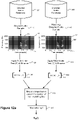
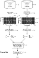
- Figure 12a illustrates the initial part of the training process in which a current filter under consideration (filter F(i)) is applied to a pair of matching audio clips and Figure 12b illustrates the same process but when the filter (F(i)) under consideration is applied to a pair of non-matching audio clips.
- a matching pair of audio clips includes the original audio clip from database 351 and the corresponding distorted version of that original audio clip from database 353; and a non-matching pair of audio clips includes an original audio clip from the database 353 and a distorted version of a different original audio clip from the database 353.
- step s1 the original audio clip is read out from the database 351 and in step s3 the corresponding (matching) distorted audio clip is read out from database 353.
- step s5 a spectrogram 357 is determined for the original audio clip and in step s7 a spectrogram 359 is determined for the distorted audio clip.
- step s9 the current filter under consideration (F(i)) is applied to the spectrogram 357 and the result binarised to generate the binary vector 361.
- step s11 the same filter (F(i)) is applied to the spectrogram 359 and the result binarised to generate the binary vector 363.
- step s13 a bit-wise comparison is performed between the vectors 361 and 363 to determine the number of non-matching bits. This can be achieved using a simple XOR comparison between the two vectors.
- step s15 the determined number of non-matching bits is normalised by the length of the spectrogram (L) - to take into account the different lengths of the matching pairs of audio clips stored in the databases 351 and 353, to generate a value B M (i) that effectively defines the percentage of non-matching bits (i.e. the bit error rate) between the matching pair of audio clips.
- a very similar process is carried out for a non-matching pair of audio clips taken from the databases 351 and 353.
- step s21 an original audio clip is read out from the database 351 and in step s23 a non-matching distorted audio clip is read out from database 353. If the two non-matching audio clips have different durations then the duration of the longer clip can be truncated to match that of the shorter clip.
- step s25 a spectrogram 365 is determined for the original audio clip and in step s27 a spectrogram 367 is determined for the non-matching distorted audio clip.
- step s29 the filter under consideration (F(i)) is applied to the spectrogram 365 and the result binarised to generate the binary vector 369.
- step s31 the same filter (F(i)) is applied to the spectrogram 367 and the result binarised to generate the binary vector 371.
- step s33 a bit-wise comparison is performed between the vectors 369 and 371 to determine the number of non-matching bits. As before, this can be achieved by using a simple XOR comparison between the two vectors.
- step s35 the determined number of non-matching bits is normalised by the length of the spectrogram (L) - to take in to account the different lengths of the matching pairs of audio clips stored in the databases 351 and 353, to generate a value B N (i) that effectively defines the percentage of non-matching bits (i.e. the bit error rate) for the non-matching pair of audio clips.
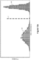
- the process illustrated in Figure 12a is carried out using the same filter (F(i)) on each of a number (N M - for example 100) of matching pairs of audio clips; and the process illustrated in Figure 12b is carried out using the same filter (F(i)) on each of a number (N N - which may also be 100) of non-matching pairs of audio clips. If the N M values thus obtained for B M (i) and the N N values thus obtained for B N (i) are plotted in a histogram then they will each exhibit a Normal distribution that is characterised by a mean value and variance.
- Distribution 401 is the distribution obtained for the matching pairs and distribution 403 is the distribution for the non-matching pairs.
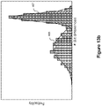
- the filter under consideration is a poor candidate then the distribution for the matching pairs and the distribution for the non-matching pairs will be closer together and possibly overlapping - such as the example distributions 405 and 407 shown in Figure 13b .
- the aim of that optimisation can be to minimise the chance of "false positives” (falsely declaring a pair a "match”) and to minimise the chance of false negatives (falsely declaring a pair a "non-match”) - when the generated fingerprint is being matched against the database fingerprints.
- a threshold can be defined between the two distributions that can be used to define if a pair of audio clips are matching or non-matching.
- the bit error rate between them is less than the threshold (i.e. B ⁇ y) then it can be assumed that the pair is a matching pair; whereas if the determined bit error rate is above the threshold (i.e. B>y) then it can be assumed that the pair is a non-matching pair.
- ⁇ N is the mean bit error rate for a pair of non-matching fingerprints
- ⁇ N is the standard deviation of the bit error rate for a pair of non-matching fingerprints
- erfc is the standard complimentary error function
- ⁇ M is the mean bit error rate for a pair of matching fingerprints
- ⁇ M is the standard deviation of the bit error rate for a pair of matching fingerprints
- ⁇ N is the mean bit error rate for a pair of non-matching fingerprints
- ⁇ N is the standard deviation of the bit error rate for a pair of non-matching fingerprints
- erfc is the standard complimentary error function.
- the aim of the optimisation process is to find the set 45 of filters with aggregate parameters ( ⁇ M , ⁇ N , ⁇ M , ⁇ N ) that result in the highest score S (1) .
- n is the number of filters in the set 45.
- COV (l,k) is the covariance between filter l and filter k.
- the means and variances for individual filters for both matching and non-matching pairs of audio clips can be determined from the training process discussed above with reference to Figures 12a and 12b .
- N f the number of filters considered, which as discussed above is roughly 16,000
- Such a trellis 409 is illustrated in Figure 14 .
- the N f filters are ordered vertically and represented by a respective node 411 in the left hand column of the trellis 409.
- This column of nodes 411 is then repeated n times so that there are n columns of nodes 411, where n is the size of the set of filters to be created.
- n is set to the value 32 as this facilitates computation using a 32 bit or a 64 bit central processing unit (CPU). Connections (edges) from every node in the left hand column to every node in the next column are then made and scored using the above score (S (1) ) that is to be maximised.
- the path having the maximum score S (1) through the trellis 409 identifies the optimum set 45 of filters. For example, the path having the maximum score S (1) is illustrated as the path 415 shown in bold in Figure 14 .
- the updated metrics can then be used to recalculated the score S at at node r.
- the trellis 409 illustrated in Figure 14 is a graphical representation that facilitates understanding of the dynamic programming calculations that will be made by the training computer (which may be a dedicated training computer or in some cases may be the audio matching server 5) during the above training process.
- the actual calculations will be performed with suitable data structures within the memory of the training computer.
- the resulting optimised set 45 of filters will then be provided to user devices 1 so that they can generate the fine fingerprints 43. They will also be used by the training computer (or by the audio matching server 5) to generate the fine database fingerprints 323.
- the rows (or columns) of the fine fingerprint 43 have to be ordered so that there is some level of coherence in the fine fingerprint - i.e. filters that tend to produce similar results are ordered next to each other. In this way, filters that are generally correlated with each other are next to each other. This results in a fine fingerprint 43 that is less random in appearance - i.e. having larger areas of the same binary value (as illustrated in by the fingerprint 43-2 shown in Figure 6 ).
- the covariance values that are determined for two filters gives information on the correlation between the two fiulters. Therefore, we can determine the order of the filters in dependence upon the covariance values calculated for the n filters in the optimised set 45 of filters. This can be achieved, for example, using a reverse Cuthill-Mckee ordering on the largest covariance values for the n filters.
- the determined ordering information is also provided to the user devices 1 with the first optimised set 45 of filters.
- a similar training process can then be applied to determine the second set 221 of optimised filters.
- the main difference between this training process and the training process discussed above is that the filters are applied to fine fingerprints that are obtained for the matching and non-matching pairs of audio clips. Also, the optimisation process has a different goal.
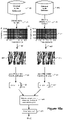
- Figures 15a and 15b illustrate the processing performed to determine the B (i) M values for matching pairs of audio clips and the B (i) N values for non-matching pairs of audio clips.
- fine fingerprints 441, 443, 445 and 447 are determined in steps s41, s43, s45 and s47 respectively, using the above first set 45 of optimised filters and using the ordering information to define how the fine fingerprints are formed.
- the current filter under test (F(i)) is then applied to the fine fingerprints and the bitwise comparison is performed as before to determine B M (i) and B N (i).
- the optimisation goal for determining the second set 221 of filters is to find the filters that will result in a minimum subset of possible matching database entries whilst not excluding the correct entry in the database 15 - which will therefore reduce the number of comparisons required of the fine fingerprint 43.
- the database entries that must be searched in more detail are those that fall below some second threshold ⁇ (2) (which will be different from the ⁇ threshold used above).
- the task is to find the combination of filters that maximises this score; where the aggregate mean and variances ( ⁇ (2) N , ⁇ (2) M , ⁇ (2) N and ⁇ (2) M ) for any combination of filters can be calculated using the means, variances and covariances determined for each filter of the combination during the training process illustrated in Figure 15 .
- n is the number of filters in the second set 221 of optimised filters.
- COV (2)(l,k) is the covariance between filter l and filter k.
- the means, variances and covariances for individual filters for both matching and non-matching pairs of audio clips are determined from the training process discussed above with reference to Figures 15a and 15b .
- the path scoring can be accumulated during the dynamic programming path propagation to find the best path through the trellis - so it is not necessatry to recalculate the score S (2) each time a new node (filter) is added to a candidate path.
- the updated metrics can then be used to recalculated the score S (2) at node r.
- the user device generated a fine fingerprint which it transmitted to the audio matching server which generated a coarse fingerprint from the fine fingerprint.
- the user device itself may calculate the coarse fingerprint and send it together with the fine fingerprint to the audio matching server.
- a coarse fingerprint was generated from the fine fingerprint. This is particularly beneficial in the scenario where a user device determines the fine fingerprint and sends it to a remote server for comparison with the database entries. In other embodiments where the user device calculates both the coarse fingerprint and the fine fingerprint, the coarse fingerprint can be determined from the spectrogram of the captured audio rather than from the fine fingerprint. In this case, the second set 221 of optimised filters would be trained using the second score described above - but based on binarised vectors obtained by applying the filters to the spectrogram rather than to the fine fingerprint. This would also be the case if the user device transmitted the fine fingerprint and the spectrogram to the remote server - which then calculated the coarse fingerprint from the received spectrogram. However, this latter possibility is not preferred as it requires the spectrogram (which is a large data structure) to be transmitted from the user device to the server.
- the user device or the audio matching server generated a coarse fingerprint from a fine fingerprint using a set of optimised filters that are applied to the fine fingerprint.
- the coarse fingerprint could be generated simply by sub-sampling the fine fingerprint or by averaging the fine fingerprint.
- the audio matching server and the database may form part of the user device itself. In this case, there is no need for the user device to transmit any fingerprint data over the telecommunications network or over the computer network. This data would simply be sent between the different software components being run in the user device (although any results of the matching may be transmitted over the network to a server).
- Figures 12 and 15 illustrate two databases - one for original audio samples and the other for distorted versions of the audio samples. As those skilled in the art will appreciate, all these audio samples may just be stored in a single database rather than in two separate databases. Similarly, these figures illustrate that spectrograms are determined for each audio sample in a matched pair and for each audio sample in a non-matched pair. As those skilled in the art will appreciate, the same audio samples may be included in a pair of matched audio samples and in a pair of non-matching audio samples. In this case it is clearly not necessary to determine the spectrogram for the same audio sample twice. That is, the optimisation process only needs to determine the spectrogram for each audio sample in the database and then apply each filter to each spectrogram.
- the optimisation process set an acceptable false positive rate and then found the set of filters that minimised the false negative rate.
- the optimisation process may set an acceptable false negative rate and then find the set of filters that minimises the false positive rate.
- the optimisation process may set an acceptable false positive rate and an acceptable false negative rate and then find the set of filters that minimises some other cost function.
- the dynamic programming processes selected the path through the trellis 409 having the highest score.
- the best or optimum path that is chosen does not have to be the one having the highest score - for example the path having the second highest or the third highest score could be used instead.
- a user device captured sounds using a microphone and the audio samples were processed using a software application stored on the user device.
- this processing may be formed by dedicated hardware circuits, although software is preferred due to its ability to be added to the portable user device after manufacture and its ability to be updated once loaded.
- the software for causing the portable user device to operate in the above manner may be provided as a signal or on a carrier such as compact disc or other carrier medium. Additionally, a range of other portable devices may be used, such as laptop computers, PDAs, tablet computers and the like.
- the software forming part of the audio matching server may be replaced with suitable hardware circuits - such as Application Specific Integrated Circuits.
- the above embodiments have described a fingerprint based audio matching system.
- This system may also be used together with a watermarking type of audio matching system that detects hidden watermarks that have been hidden in the audio.
- a watermarking type of audio matching system that detects hidden watermarks that have been hidden in the audio.
- the above fingerprint audio recognition can be used to identify the captured audio.
- the sets of optimised filters used five different types of filter. In other embodiments more or fewer types of filter may be used. Further it is not essential to use filters that are rectangular in shape - other irregular shapes of filters could be used (such as "L" shaped filters).
- the shape of filter just defines the neighbouring values in the spectrogram (or in the fine fingerprint) that are weighted by the corresponding coefficient in the filter and then combined together.
- each filter of the first set of optimised filters was stepped along the spectrogram one time step at a time.
- the fine fingerprint could omit some of these data points - at the start or end of the spectrogram.
- a larger step size could also be used - for example one time point could be skipped at each step.
- the fine fingerprint would have a temporal duration half that of the spectrogram. So if the spectrogram had 500 time points then the generated fine fingerprint would have 250 time points.
- the coarse fingerprint was generated with a time resolution 1/10 th that of the spectrogram. That is 10 time points were skipped between steps when the second set of optimised filters were stepped across the spectrogram.
- step sizes could of course be used to achieve different compression of the data in the time dimension.
- the audio signal captured by the user device was an acoustic signal.
- the user device may capture the audio signal as an electromagnetic signal received via the antenna of the user device; or in the case that the user device is not a portable device and is, for example, a personal computer or a set-top-box or a smart television, the audio signal may be captured via a signal received over a broadcast television network (e.g. a satellite network, a cable network, an ADSL network or the like), the Internet or some other computer network.
- a broadcast television network e.g. a satellite network, a cable network, an ADSL network or the like
- each entry in the database contained a coarse fingerprint and a fine fingerprint.
- each database entry may not contain the coarse fingerprint - which may instead be generated when needed from the fine database fingerprint.
- the coarse database fingerprint may be generated from the fine database fingerprint in a number of different ways - just as the coarse query fingerprint can be determined in a number of different ways from the fine query fingerprint. These different ways of determining the coarse fingerprint from the fine fingerprint are discussed above and will not be repeated again. Needless to say, the technique used to generate the coarse query fingerprint should be the same as the technique that is used to generate the coarse database fingerprint.
Landscapes
- Engineering & Computer Science (AREA)
- Theoretical Computer Science (AREA)
- Physics & Mathematics (AREA)
- Multimedia (AREA)
- General Engineering & Computer Science (AREA)
- Data Mining & Analysis (AREA)
- General Physics & Mathematics (AREA)
- Databases & Information Systems (AREA)
- Library & Information Science (AREA)
- Health & Medical Sciences (AREA)
- Human Computer Interaction (AREA)
- Signal Processing (AREA)
- Acoustics & Sound (AREA)
- Computational Linguistics (AREA)
- Audiology, Speech & Language Pathology (AREA)
- Mathematical Physics (AREA)
- Information Retrieval, Db Structures And Fs Structures Therefor (AREA)
- Telephonic Communication Services (AREA)
Applications Claiming Priority (3)
| Application Number | Priority Date | Filing Date | Title |
|---|---|---|---|
| GB1613960.2A GB2556023B (en) | 2016-08-15 | 2016-08-15 | Audio matching |
| EP17758252.5A EP3497587A1 (de) | 2016-08-15 | 2017-07-28 | Tonabstimmung |
| PCT/GB2017/052219 WO2018033696A1 (en) | 2016-08-15 | 2017-07-28 | Audio matching |
Related Parent Applications (1)
| Application Number | Title | Priority Date | Filing Date |
|---|---|---|---|
| EP17758252.5A Division EP3497587A1 (de) | 2016-08-15 | 2017-07-28 | Tonabstimmung |
Publications (3)
| Publication Number | Publication Date |
|---|---|
| EP4006748A1 true EP4006748A1 (de) | 2022-06-01 |
| EP4006748C0 EP4006748C0 (de) | 2024-06-19 |
| EP4006748B1 EP4006748B1 (de) | 2024-06-19 |
Family
ID=56985973
Family Applications (2)
| Application Number | Title | Priority Date | Filing Date |
|---|---|---|---|
| EP17758252.5A Pending EP3497587A1 (de) | 2016-08-15 | 2017-07-28 | Tonabstimmung |
| EP22151836.8A Active EP4006748B1 (de) | 2016-08-15 | 2017-07-28 | Tonabstimmung |
Family Applications Before (1)
| Application Number | Title | Priority Date | Filing Date |
|---|---|---|---|
| EP17758252.5A Pending EP3497587A1 (de) | 2016-08-15 | 2017-07-28 | Tonabstimmung |
Country Status (7)
| Country | Link |
|---|---|
| US (2) | US11106730B2 (de) |
| EP (2) | EP3497587A1 (de) |
| CN (1) | CN109891404B (de) |
| ES (1) | ES2987078T3 (de) |
| GB (1) | GB2556023B (de) |
| PL (1) | PL4006748T3 (de) |
| WO (1) | WO2018033696A1 (de) |
Families Citing this family (11)
| Publication number | Priority date | Publication date | Assignee | Title |
|---|---|---|---|---|
| EP3738287B1 (de) * | 2018-01-10 | 2021-09-08 | Rezzonation B.V. | Inhaltsabgleichssystem |
| CN110047515B (zh) * | 2019-04-04 | 2021-04-20 | 腾讯音乐娱乐科技(深圳)有限公司 | 一种音频识别方法、装置、设备及存储介质 |
| IT202000015781A1 (it) * | 2020-06-30 | 2021-12-30 | Telecom Italia Spa | Monitoraggio dell’audience pubblicitaria in un sistema di distribuzione di contenuti |
| KR102380540B1 (ko) * | 2020-09-14 | 2022-04-01 | 네이버 주식회사 | 음원을 검출하기 위한 전자 장치 및 그의 동작 방법 |
| US20220351425A1 (en) * | 2021-04-30 | 2022-11-03 | Mobeus Industries, Inc. | Integrating overlaid digital content into data via processing circuitry using an audio buffer |
| US11508395B1 (en) * | 2021-05-03 | 2022-11-22 | Dell Products, L.P. | Intelligent selection of audio signatures based upon contextual information to perform management actions |
| CN113889146B (zh) * | 2021-09-22 | 2025-05-27 | 北京小米移动软件有限公司 | 音频识别方法、装置、电子设备和存储介质 |
| US12586552B2 (en) | 2021-10-11 | 2026-03-24 | Adobe Inc. | Multi-level audio segmentation using deep embeddings |
| US20230129350A1 (en) * | 2021-10-25 | 2023-04-27 | Adobe Inc. | Section-based music similarity searching |
| US11417099B1 (en) * | 2021-11-08 | 2022-08-16 | 9219-1568 Quebec Inc. | System and method for digital fingerprinting of media content |
| CN118825917B (zh) * | 2024-06-27 | 2025-02-14 | 成都新创界自动化设备有限公司 | 一种基于物联网的高压开关柜在线监测装置 |
Citations (3)
| Publication number | Priority date | Publication date | Assignee | Title |
|---|---|---|---|---|
| WO2002045273A2 (en) | 2000-11-30 | 2002-06-06 | Scientific Generics Limited | Communication system |
| WO2008145994A1 (en) | 2007-05-29 | 2008-12-04 | Intrasonics S.A.R.L. | Recovery of hidden data embedded in an audio signal |
| WO2009144470A1 (en) | 2008-05-29 | 2009-12-03 | Intrasonics S.à.r.l. | Data embedding system |
Family Cites Families (16)
| Publication number | Priority date | Publication date | Assignee | Title |
|---|---|---|---|---|
| US7013301B2 (en) * | 2003-09-23 | 2006-03-14 | Predixis Corporation | Audio fingerprinting system and method |
| EP1958362A4 (de) * | 2005-11-29 | 2010-03-17 | Google Inc | Detektierung von sich wiederholendem inhalt in ausstrahlungsmedien |
| WO2009107049A2 (en) * | 2008-02-26 | 2009-09-03 | Koninklijke Philips Electronics N.V. | Content identification method |
| EP2323046A1 (de) * | 2009-10-16 | 2011-05-18 | Telefónica, S.A. | Verfahren zur Erkennung einer Audio- und Videokopie in Multimediaströmen |
| CN101882439B (zh) * | 2010-06-10 | 2012-02-08 | 复旦大学 | 一种基于Zernike矩的压缩域音频指纹方法 |
| CN101980197B (zh) * | 2010-10-29 | 2012-10-31 | 北京邮电大学 | 一种基于长时结构声纹的多层滤波音频检索方法和装置 |
| US8584197B2 (en) * | 2010-11-12 | 2013-11-12 | Google Inc. | Media rights management using melody identification |
| US9093120B2 (en) * | 2011-02-10 | 2015-07-28 | Yahoo! Inc. | Audio fingerprint extraction by scaling in time and resampling |
| CN102314875B (zh) * | 2011-08-01 | 2016-04-27 | 北京音之邦文化科技有限公司 | 一种音频文件的识别方法和装置 |
| US8949872B2 (en) * | 2011-12-20 | 2015-02-03 | Yahoo! Inc. | Audio fingerprint for content identification |
| US8681950B2 (en) * | 2012-03-28 | 2014-03-25 | Interactive Intelligence, Inc. | System and method for fingerprinting datasets |
| US9159327B1 (en) * | 2012-12-20 | 2015-10-13 | Google Inc. | System and method for adding pitch shift resistance to an audio fingerprint |
| US9390727B2 (en) * | 2014-01-13 | 2016-07-12 | Facebook, Inc. | Detecting distorted audio signals based on audio fingerprinting |
| JP6587625B2 (ja) * | 2014-03-04 | 2019-10-09 | インタラクティブ・インテリジェンス・グループ・インコーポレイテッド | オーディオ指紋探索の最適化のためのシステムおよび方法 |
| US10157620B2 (en) * | 2014-03-04 | 2018-12-18 | Interactive Intelligence Group, Inc. | System and method to correct for packet loss in automatic speech recognition systems utilizing linear interpolation |
| CN105551485B (zh) * | 2015-11-30 | 2020-04-21 | 讯飞智元信息科技有限公司 | 语音文件检索方法及系统 |
-
2016
- 2016-08-15 GB GB1613960.2A patent/GB2556023B/en active Active
-
2017
- 2017-07-28 ES ES22151836T patent/ES2987078T3/es active Active
- 2017-07-28 EP EP17758252.5A patent/EP3497587A1/de active Pending
- 2017-07-28 PL PL22151836.8T patent/PL4006748T3/pl unknown
- 2017-07-28 US US16/325,692 patent/US11106730B2/en active Active
- 2017-07-28 EP EP22151836.8A patent/EP4006748B1/de active Active
- 2017-07-28 CN CN201780063352.3A patent/CN109891404B/zh active Active
- 2017-07-28 WO PCT/GB2017/052219 patent/WO2018033696A1/en not_active Ceased
-
2021
- 2021-04-09 US US17/227,001 patent/US11556587B2/en active Active
Patent Citations (3)
| Publication number | Priority date | Publication date | Assignee | Title |
|---|---|---|---|---|
| WO2002045273A2 (en) | 2000-11-30 | 2002-06-06 | Scientific Generics Limited | Communication system |
| WO2008145994A1 (en) | 2007-05-29 | 2008-12-04 | Intrasonics S.A.R.L. | Recovery of hidden data embedded in an audio signal |
| WO2009144470A1 (en) | 2008-05-29 | 2009-12-03 | Intrasonics S.à.r.l. | Data embedding system |
Non-Patent Citations (3)
| Title |
|---|
| CANO P ET AL: "A review of algorithms for audio fingerprinting", PROCEEDINGS OF THE 2003 IEEE RADAR CONFERENCE. HUNTSVILLE, AL, MAY 5 - 8, 2003; [IEEE RADAR CONFERENCE], NEW YORK, NY : IEEE, US, 9 December 2002 (2002-12-09), pages 169 - 173, XP010642539, ISBN: 978-0-7803-7920-6 * |
| JAAP HAITSMA ET AL: "A Highly Robust Audio Fingerprinting System With an Efficient Search Strategy", JOURNAL OF NEW MUSIC RESEARCH, 1 June 2003 (2003-06-01), pages 211 - 221, XP055259740, Retrieved from the Internet <URL:https://www.tandfonline.com/doi/abs/10.1076/jnmr.32.2.211.16746> [retrieved on 20160318], DOI: 10.1076/jnmr.32.2.211.16746 * |
| NAINI ROHIT ET AL: "Fingerprint information maximization for content identification", 2014 IEEE INTERNATIONAL CONFERENCE ON ACOUSTICS, SPEECH AND SIGNAL PROCESSING (ICASSP), IEEE, 4 May 2014 (2014-05-04), pages 3809 - 3813, XP032616951, DOI: 10.1109/ICASSP.2014.6854314 * |
Also Published As
| Publication number | Publication date |
|---|---|
| GB2556023B (en) | 2022-02-09 |
| GB2556023A (en) | 2018-05-23 |
| EP4006748C0 (de) | 2024-06-19 |
| US20190213214A1 (en) | 2019-07-11 |
| US11556587B2 (en) | 2023-01-17 |
| US20210224318A1 (en) | 2021-07-22 |
| PL4006748T3 (pl) | 2024-10-28 |
| EP4006748B1 (de) | 2024-06-19 |
| ES2987078T3 (es) | 2024-11-13 |
| GB201613960D0 (en) | 2016-09-28 |
| WO2018033696A1 (en) | 2018-02-22 |
| EP3497587A1 (de) | 2019-06-19 |
| CN109891404B (zh) | 2023-10-24 |
| US11106730B2 (en) | 2021-08-31 |
| CN109891404A (zh) | 2019-06-14 |
Similar Documents
| Publication | Publication Date | Title |
|---|---|---|
| US11556587B2 (en) | Audio matching | |
| US9798513B1 (en) | Audio content fingerprinting based on two-dimensional constant Q-factor transform representation and robust audio identification for time-aligned applications | |
| US7461392B2 (en) | System and method for identifying and segmenting repeating media objects embedded in a stream | |
| EP2507790B1 (de) | Verfahren und system für robustes audio-hashing | |
| CN101669308B (zh) | 表征媒体的方法和装置 | |
| CN102317957B (zh) | 改进的图像识别 | |
| US7653921B2 (en) | System and method for providing user control over repeating objects embedded in a stream | |
| US9715626B2 (en) | Method and apparatus for automatically recognizing input audio and/or video streams | |
| US20140310006A1 (en) | Method to generate audio fingerprints | |
| US20030091323A1 (en) | Signal processing apparatus and method, recording medium, and program | |
| JP2005522744A (ja) | 音声コンテンツを特定する方法 | |
| GB2598691A (en) | Audio matching | |
| Parvin et al. | An efficient music retrieval using noise cancellation |
Legal Events
| Date | Code | Title | Description |
|---|---|---|---|
| PUAI | Public reference made under article 153(3) epc to a published international application that has entered the european phase |
Free format text: ORIGINAL CODE: 0009012 |
|
| STAA | Information on the status of an ep patent application or granted ep patent |
Free format text: STATUS: THE APPLICATION HAS BEEN PUBLISHED |
|
| AC | Divisional application: reference to earlier application |
Ref document number: 3497587 Country of ref document: EP Kind code of ref document: P |
|
| AK | Designated contracting states |
Kind code of ref document: A1 Designated state(s): AL AT BE BG CH CY CZ DE DK EE ES FI FR GB GR HR HU IE IS IT LI LT LU LV MC MK MT NL NO PL PT RO RS SE SI SK SM TR |
|
| STAA | Information on the status of an ep patent application or granted ep patent |
Free format text: STATUS: REQUEST FOR EXAMINATION WAS MADE |
|
| 17P | Request for examination filed |
Effective date: 20221201 |
|
| RBV | Designated contracting states (corrected) |
Designated state(s): AL AT BE BG CH CY CZ DE DK EE ES FI FR GB GR HR HU IE IS IT LI LT LU LV MC MK MT NL NO PL PT RO RS SE SI SK SM TR |
|
| P01 | Opt-out of the competence of the unified patent court (upc) registered |
Effective date: 20230515 |
|
| STAA | Information on the status of an ep patent application or granted ep patent |
Free format text: STATUS: EXAMINATION IS IN PROGRESS |
|
| 17Q | First examination report despatched |
Effective date: 20230807 |
|
| GRAP | Despatch of communication of intention to grant a patent |
Free format text: ORIGINAL CODE: EPIDOSNIGR1 |
|
| STAA | Information on the status of an ep patent application or granted ep patent |
Free format text: STATUS: GRANT OF PATENT IS INTENDED |
|
| INTG | Intention to grant announced |
Effective date: 20240108 |
|
| GRAS | Grant fee paid |
Free format text: ORIGINAL CODE: EPIDOSNIGR3 |
|
| GRAA | (expected) grant |
Free format text: ORIGINAL CODE: 0009210 |
|
| STAA | Information on the status of an ep patent application or granted ep patent |
Free format text: STATUS: THE PATENT HAS BEEN GRANTED |
|
| AC | Divisional application: reference to earlier application |
Ref document number: 3497587 Country of ref document: EP Kind code of ref document: P |
|
| AK | Designated contracting states |
Kind code of ref document: B1 Designated state(s): AL AT BE BG CH CY CZ DE DK EE ES FI FR GB GR HR HU IE IS IT LI LT LU LV MC MK MT NL NO PL PT RO RS SE SI SK SM TR |
|
| REG | Reference to a national code |
Ref country code: GB Ref legal event code: FG4D |
|
| REG | Reference to a national code |
Ref country code: CH Ref legal event code: EP |
|
| REG | Reference to a national code |
Ref country code: DE Ref legal event code: R096 Ref document number: 602017082777 Country of ref document: DE |
|
| U01 | Request for unitary effect filed |
Effective date: 20240719 |
|
| U07 | Unitary effect registered |
Designated state(s): AT BE BG DE DK EE FI FR IT LT LU LV MT NL PT SE SI Effective date: 20240729 |
|
| P04 | Withdrawal of opt-out of the competence of the unified patent court (upc) registered |
Free format text: CASE NUMBER: APP_43412/2024 Effective date: 20240724 |
|
| U20 | Renewal fee for the european patent with unitary effect paid |
Year of fee payment: 8 Effective date: 20240821 |
|
| PG25 | Lapsed in a contracting state [announced via postgrant information from national office to epo] |
Ref country code: HR Free format text: LAPSE BECAUSE OF FAILURE TO SUBMIT A TRANSLATION OF THE DESCRIPTION OR TO PAY THE FEE WITHIN THE PRESCRIBED TIME-LIMIT Effective date: 20240619 |
|
| PG25 | Lapsed in a contracting state [announced via postgrant information from national office to epo] |
Ref country code: GR Free format text: LAPSE BECAUSE OF FAILURE TO SUBMIT A TRANSLATION OF THE DESCRIPTION OR TO PAY THE FEE WITHIN THE PRESCRIBED TIME-LIMIT Effective date: 20240920 |
|
| PG25 | Lapsed in a contracting state [announced via postgrant information from national office to epo] |
Ref country code: NO Free format text: LAPSE BECAUSE OF FAILURE TO SUBMIT A TRANSLATION OF THE DESCRIPTION OR TO PAY THE FEE WITHIN THE PRESCRIBED TIME-LIMIT Effective date: 20240919 Ref country code: HR Free format text: LAPSE BECAUSE OF FAILURE TO SUBMIT A TRANSLATION OF THE DESCRIPTION OR TO PAY THE FEE WITHIN THE PRESCRIBED TIME-LIMIT Effective date: 20240619 Ref country code: GR Free format text: LAPSE BECAUSE OF FAILURE TO SUBMIT A TRANSLATION OF THE DESCRIPTION OR TO PAY THE FEE WITHIN THE PRESCRIBED TIME-LIMIT Effective date: 20240920 Ref country code: RS Free format text: LAPSE BECAUSE OF FAILURE TO SUBMIT A TRANSLATION OF THE DESCRIPTION OR TO PAY THE FEE WITHIN THE PRESCRIBED TIME-LIMIT Effective date: 20240919 |
|
| REG | Reference to a national code |
Ref country code: ES Ref legal event code: FG2A Ref document number: 2987078 Country of ref document: ES Kind code of ref document: T3 Effective date: 20241113 |
|
| P05 | Withdrawal of opt-out of the competence of the unified patent court (upc) changed |
Free format text: CASE NUMBER: APP_43412/2024 Effective date: 20240729 |
|
| PG25 | Lapsed in a contracting state [announced via postgrant information from national office to epo] |
Ref country code: IS Free format text: LAPSE BECAUSE OF FAILURE TO SUBMIT A TRANSLATION OF THE DESCRIPTION OR TO PAY THE FEE WITHIN THE PRESCRIBED TIME-LIMIT Effective date: 20241019 |
|
| PG25 | Lapsed in a contracting state [announced via postgrant information from national office to epo] |
Ref country code: CZ Free format text: LAPSE BECAUSE OF FAILURE TO SUBMIT A TRANSLATION OF THE DESCRIPTION OR TO PAY THE FEE WITHIN THE PRESCRIBED TIME-LIMIT Effective date: 20240619 |
|
| PG25 | Lapsed in a contracting state [announced via postgrant information from national office to epo] |
Ref country code: RO Free format text: LAPSE BECAUSE OF FAILURE TO SUBMIT A TRANSLATION OF THE DESCRIPTION OR TO PAY THE FEE WITHIN THE PRESCRIBED TIME-LIMIT Effective date: 20240619 Ref country code: SK Free format text: LAPSE BECAUSE OF FAILURE TO SUBMIT A TRANSLATION OF THE DESCRIPTION OR TO PAY THE FEE WITHIN THE PRESCRIBED TIME-LIMIT Effective date: 20240619 |
|
| PG25 | Lapsed in a contracting state [announced via postgrant information from national office to epo] |
Ref country code: SM Free format text: LAPSE BECAUSE OF FAILURE TO SUBMIT A TRANSLATION OF THE DESCRIPTION OR TO PAY THE FEE WITHIN THE PRESCRIBED TIME-LIMIT Effective date: 20240619 |
|
| PG25 | Lapsed in a contracting state [announced via postgrant information from national office to epo] |
Ref country code: SM Free format text: LAPSE BECAUSE OF FAILURE TO SUBMIT A TRANSLATION OF THE DESCRIPTION OR TO PAY THE FEE WITHIN THE PRESCRIBED TIME-LIMIT Effective date: 20240619 Ref country code: SK Free format text: LAPSE BECAUSE OF FAILURE TO SUBMIT A TRANSLATION OF THE DESCRIPTION OR TO PAY THE FEE WITHIN THE PRESCRIBED TIME-LIMIT Effective date: 20240619 Ref country code: RO Free format text: LAPSE BECAUSE OF FAILURE TO SUBMIT A TRANSLATION OF THE DESCRIPTION OR TO PAY THE FEE WITHIN THE PRESCRIBED TIME-LIMIT Effective date: 20240619 Ref country code: IS Free format text: LAPSE BECAUSE OF FAILURE TO SUBMIT A TRANSLATION OF THE DESCRIPTION OR TO PAY THE FEE WITHIN THE PRESCRIBED TIME-LIMIT Effective date: 20241019 Ref country code: CZ Free format text: LAPSE BECAUSE OF FAILURE TO SUBMIT A TRANSLATION OF THE DESCRIPTION OR TO PAY THE FEE WITHIN THE PRESCRIBED TIME-LIMIT Effective date: 20240619 |
|
| REG | Reference to a national code |
Ref country code: CH Ref legal event code: PL |
|
| PG25 | Lapsed in a contracting state [announced via postgrant information from national office to epo] |
Ref country code: MC Free format text: LAPSE BECAUSE OF FAILURE TO SUBMIT A TRANSLATION OF THE DESCRIPTION OR TO PAY THE FEE WITHIN THE PRESCRIBED TIME-LIMIT Effective date: 20240619 |
|
| PG25 | Lapsed in a contracting state [announced via postgrant information from national office to epo] |
Ref country code: MC Free format text: LAPSE BECAUSE OF FAILURE TO SUBMIT A TRANSLATION OF THE DESCRIPTION OR TO PAY THE FEE WITHIN THE PRESCRIBED TIME-LIMIT Effective date: 20240619 |
|
| PG25 | Lapsed in a contracting state [announced via postgrant information from national office to epo] |
Ref country code: CH Free format text: LAPSE BECAUSE OF NON-PAYMENT OF DUE FEES Effective date: 20240731 |
|
| PLBE | No opposition filed within time limit |
Free format text: ORIGINAL CODE: 0009261 |
|
| STAA | Information on the status of an ep patent application or granted ep patent |
Free format text: STATUS: NO OPPOSITION FILED WITHIN TIME LIMIT |
|
| 26N | No opposition filed |
Effective date: 20250320 |
|
| PG25 | Lapsed in a contracting state [announced via postgrant information from national office to epo] |
Ref country code: IE Free format text: LAPSE BECAUSE OF NON-PAYMENT OF DUE FEES Effective date: 20240728 |
|
| U20 | Renewal fee for the european patent with unitary effect paid |
Year of fee payment: 9 Effective date: 20250728 |
|
| PGFP | Annual fee paid to national office [announced via postgrant information from national office to epo] |
Ref country code: ES Payment date: 20250811 Year of fee payment: 9 |
|
| PGFP | Annual fee paid to national office [announced via postgrant information from national office to epo] |
Ref country code: PL Payment date: 20250704 Year of fee payment: 9 |
|
| PGFP | Annual fee paid to national office [announced via postgrant information from national office to epo] |
Ref country code: GB Payment date: 20250728 Year of fee payment: 9 |
|
| REG | Reference to a national code |
Ref country code: GB Ref legal event code: 732E Free format text: REGISTERED BETWEEN 20251211 AND 20251217 |
|
| U1K | Transfer of rights of the unitary patent after the registration of the unitary effect |
Owner name: IPSOS MORI UK LIMITED; GB |
|
| PG25 | Lapsed in a contracting state [announced via postgrant information from national office to epo] |
Ref country code: CY Free format text: LAPSE BECAUSE OF FAILURE TO SUBMIT A TRANSLATION OF THE DESCRIPTION OR TO PAY THE FEE WITHIN THE PRESCRIBED TIME-LIMIT; INVALID AB INITIO Effective date: 20170728 |
|
| PG25 | Lapsed in a contracting state [announced via postgrant information from national office to epo] |
Ref country code: HU Free format text: LAPSE BECAUSE OF FAILURE TO SUBMIT A TRANSLATION OF THE DESCRIPTION OR TO PAY THE FEE WITHIN THE PRESCRIBED TIME-LIMIT; INVALID AB INITIO Effective date: 20170728 |