EP4006762A1 - Détection et identification d'attaques ciblées d'un système informatique - Google Patents
Détection et identification d'attaques ciblées d'un système informatique Download PDFInfo
- Publication number
- EP4006762A1 EP4006762A1 EP22153459.7A EP22153459A EP4006762A1 EP 4006762 A1 EP4006762 A1 EP 4006762A1 EP 22153459 A EP22153459 A EP 22153459A EP 4006762 A1 EP4006762 A1 EP 4006762A1
- Authority
- EP
- European Patent Office
- Prior art keywords
- attack
- data
- malicious activity
- indicative
- enrichment
- Prior art date
- Legal status (The legal status is an assumption and is not a legal conclusion. Google has not performed a legal analysis and makes no representation as to the accuracy of the status listed.)
- Granted
Links
Images





Classifications
-
- G—PHYSICS
- G06—COMPUTING OR CALCULATING; COUNTING
- G06F—ELECTRIC DIGITAL DATA PROCESSING
- G06F21/00—Security arrangements for protecting computers, components thereof, programs or data against unauthorised activity
- G06F21/50—Monitoring users, programs or devices to maintain the integrity of platforms, e.g. of processors, firmware or operating systems
- G06F21/55—Detecting local intrusion or implementing counter-measures
- G06F21/552—Detecting local intrusion or implementing counter-measures involving long-term monitoring or reporting
-
- H—ELECTRICITY
- H04—ELECTRIC COMMUNICATION TECHNIQUE
- H04L—TRANSMISSION OF DIGITAL INFORMATION, e.g. TELEGRAPHIC COMMUNICATION
- H04L63/00—Network architectures or network communication protocols for network security
- H04L63/14—Network architectures or network communication protocols for network security for detecting or protecting against malicious traffic
- H04L63/1441—Countermeasures against malicious traffic
-
- G—PHYSICS
- G06—COMPUTING OR CALCULATING; COUNTING
- G06F—ELECTRIC DIGITAL DATA PROCESSING
- G06F21/00—Security arrangements for protecting computers, components thereof, programs or data against unauthorised activity
- G06F21/50—Monitoring users, programs or devices to maintain the integrity of platforms, e.g. of processors, firmware or operating systems
- G06F21/55—Detecting local intrusion or implementing counter-measures
-
- G—PHYSICS
- G06—COMPUTING OR CALCULATING; COUNTING
- G06F—ELECTRIC DIGITAL DATA PROCESSING
- G06F21/00—Security arrangements for protecting computers, components thereof, programs or data against unauthorised activity
- G06F21/50—Monitoring users, programs or devices to maintain the integrity of platforms, e.g. of processors, firmware or operating systems
- G06F21/55—Detecting local intrusion or implementing counter-measures
- G06F21/56—Computer malware detection or handling, e.g. anti-virus arrangements
-
- G—PHYSICS
- G06—COMPUTING OR CALCULATING; COUNTING
- G06F—ELECTRIC DIGITAL DATA PROCESSING
- G06F21/00—Security arrangements for protecting computers, components thereof, programs or data against unauthorised activity
- G06F21/50—Monitoring users, programs or devices to maintain the integrity of platforms, e.g. of processors, firmware or operating systems
- G06F21/55—Detecting local intrusion or implementing counter-measures
- G06F21/56—Computer malware detection or handling, e.g. anti-virus arrangements
- G06F21/566—Dynamic detection, i.e. detection performed at run-time, e.g. emulation, suspicious activities
-
- G—PHYSICS
- G06—COMPUTING OR CALCULATING; COUNTING
- G06F—ELECTRIC DIGITAL DATA PROCESSING
- G06F21/00—Security arrangements for protecting computers, components thereof, programs or data against unauthorised activity
- G06F21/50—Monitoring users, programs or devices to maintain the integrity of platforms, e.g. of processors, firmware or operating systems
- G06F21/57—Certifying or maintaining trusted computer platforms, e.g. secure boots or power-downs, version controls, system software checks, secure updates or assessing vulnerabilities
- G06F21/577—Assessing vulnerabilities and evaluating computer system security
-
- H—ELECTRICITY
- H04—ELECTRIC COMMUNICATION TECHNIQUE
- H04L—TRANSMISSION OF DIGITAL INFORMATION, e.g. TELEGRAPHIC COMMUNICATION
- H04L63/00—Network architectures or network communication protocols for network security
- H04L63/02—Network architectures or network communication protocols for network security for separating internal from external traffic, e.g. firewalls
- H04L63/0227—Filtering policies
- H04L63/0236—Filtering by address, protocol, port number or service, e.g. IP-address or URL
-
- H—ELECTRICITY
- H04—ELECTRIC COMMUNICATION TECHNIQUE
- H04L—TRANSMISSION OF DIGITAL INFORMATION, e.g. TELEGRAPHIC COMMUNICATION
- H04L63/00—Network architectures or network communication protocols for network security
- H04L63/14—Network architectures or network communication protocols for network security for detecting or protecting against malicious traffic
-
- H—ELECTRICITY
- H04—ELECTRIC COMMUNICATION TECHNIQUE
- H04L—TRANSMISSION OF DIGITAL INFORMATION, e.g. TELEGRAPHIC COMMUNICATION
- H04L63/00—Network architectures or network communication protocols for network security
- H04L63/14—Network architectures or network communication protocols for network security for detecting or protecting against malicious traffic
- H04L63/1408—Network architectures or network communication protocols for network security for detecting or protecting against malicious traffic by monitoring network traffic
- H04L63/1416—Event detection, e.g. attack signature detection
-
- H—ELECTRICITY
- H04—ELECTRIC COMMUNICATION TECHNIQUE
- H04L—TRANSMISSION OF DIGITAL INFORMATION, e.g. TELEGRAPHIC COMMUNICATION
- H04L63/00—Network architectures or network communication protocols for network security
- H04L63/14—Network architectures or network communication protocols for network security for detecting or protecting against malicious traffic
- H04L63/1408—Network architectures or network communication protocols for network security for detecting or protecting against malicious traffic by monitoring network traffic
- H04L63/1425—Traffic logging, e.g. anomaly detection
Definitions
- Computing systems are currently in wide use. Some computing systems are deployed as data centers, or to host services for a plurality of different users, among other things.
- Malicious activity data is obtained, that is indicative of attempted attacks on a computing system.
- Clusters of targets are identified and it is determined whether the malicious activity preferentially targets one cluster of targets or a set of clusters, over others.
- low prevalence attacks are identified and it is determined whether a low prevalence attack has a high concentration in one or more of the target clusters. If the malicious activity either preferentially targets a cluster, or a low prevalence attack has a high concentration in a cluster, then the attack is identified as a targeted attack, so that remediation steps can be taken.
- FIG. 1 is a block diagram of one example of a computing system architecture 100 which includes a monitored computing system 102 (that may be a hosted service or another computing system), a targeted attack identifying system 104, and remedial action system 106.
- FIG. 1 also shows that, in one example, monitored computing system 102 can be accessed by user systems 108-110 so that users 112-114 can access monitored computing system 102 through their user computing systems 108-110, respectively.
- FIG. 1 shows that a user 116 (which may be an administrative user, an on-call engineer, or another attack responder), may have access to either targeted attack identification system 104 or remedial action system 106, or both.
- targeted attack identification system 104 receives malicious activity data indicative of malicious activity that has been taken with respect to monitored computing system 102. It identifies whether the malicious activity represents a targeted attack on computing system 102 and, if so, surfaces that information for user 116. User 116 can then access remedial action system 106 to take remedial action to inhibit the attack from continuing, to inhibit future targeted attacks, etc. Control signals can also be generated so system104 can automatically control system 106 to take remedial action.
- Monitored computing system 102 may be a computing system that hosts a service for users 112-114, it may be a data center, or it may be another monitored computing system. It illustratively includes one or more processors or servers 118, a data store 120, a wide variety of different computing system functionality 122, which will vary based upon the type of computing system, and it can include a wide variety of other items 124.
- Computing system 102 also illustratively includes malicious activity detection system 126 which, itself, can include activity identifier logic 128, target identifier logic 130, attacker characteristic identifier logic 132, attack characteristic identifier logic 133, and it can include other items 134.
- Activity identifier logic 128 may be a model or a dynamic system that identifies activities or events that take place on monitored computing system 102 and that determines whether it is malicious activity.
- the output of activity identifier logic 128 may include an activity identifier that identifies the activity or sequence of steps or events that are considered to be malicious, an indication that they were indeed found to be malicious, and a confidence score that identifies the confidence that logic 128 has in its identification of the activity as being malicious.
- Target identifier logic 130 illustratively identifies the target of the malicious activity. For instance, if the malicious activity was incorporated into one or more e-mail messages, then target identifier logic 130 illustratively identifies the recipient or recipients of the e-mail message(s). It may also identify other characteristics of the target, such as the role that the target plays in an organization that uses monitored computing system 102, a department where that user resides, a physical location of the user, the recipient domain and any recipient labels, among other things.
- Attacker characteristic identifier logic 132 illustratively identifies a plurality of different characteristics of the attacker. Again, for instance, where the attack was incorporated in an e-mail message, it may identify the sender of the e-mail message, the sender domain, the sender IP address, and/or IP range, the sender country and location, etc.
- Attack characteristic identifier logic 133 may also illustratively identify different characteristics of the attack. For instance, it may identify the subject in the Re: line of an e-mail message. It may specifically identify characteristics of the e-mail message (such as changing an O in an email address line or URL to a zero or similar deceptive characteristics, URLs in the e-mail, attachment hashes in the e-mail, original recipients in the e-mail, any malware families tagged to the e-mail, a determination as to whether the e-mail was a phishing e-mail or a spam e-mail, among a wide variety of other things). Attack characteristic identifier logic 133 can also cluster the attacks (or malicious activity) based on the characteristics it identifies. This can be done by other logic as well.
- malicious activity detection system 126 When malicious activity detection system 126 identifies any malicious activity, it illustratively sends it, along with other information it has obtained or generated, to targeted attack identification system 104. System 104 determines whether the malicious activity represents a targeted attack.
- Targeted attack identification system 104 illustratively includes one or more processors or servers 136, malicious activity security system 138, a data store 140, attack surfacing logic 142 (which, itself, can include control signal generation logic 143 and other items 145), user interface mechanism 147, and it can include a wide variety of other items 144.
- Malicious activity security system 138 itself, illustratively includes signal enrichment logic 145, target/attacker/attack filtering and clustering logic 146 (hereinafter referred to as clustering logic 146), prevalence filtering logic 148, targeted attack identifier logic 149, attacker profile generator logic 150, and it can include a wide variety of other items 152.
- Malicious activity security system 138 illustratively parses and filters the malicious activity information in certain ways so it can determine whether it represents a targeted attack.
- Signal enrichment logic 145 receives the malicious activity signals indicative of malicious activity on monitored computing system 102 and enriches them with enrichment properties that can be used for clustering.
- the enrichment properties can include, for instance, target information identified by target identifier logic 130, attacker characteristics identified by logic 132 and attack characteristics identified by logic 133, among others.
- Clustering logic 146 illustratively filters the malicious activity characteristics to generate target clusters which represent groups of users that are being targeted by the malicious activity. It can then refine the clusters, or generate other clusters, based upon the characteristics of the attacks leveled against those targets.
- the clusters of attacks that are generated based on the attack characteristics identified by logic 133 can be used for example, to refine the clusters to identify targets of different kinds of attacks.
- clustering logic 146 may refine the target clusters based on features of the payload or content of an e-mail message that was incorporated in the attack. This may result in groups or clusters that are separated out based on being targeted by different types of malicious activity.
- the clusters can then again be refined (or other clusters can be generated) by clustering logic 146 based upon the attacker features or characteristics identified by attacker characteristic identifier logic 132.
- a research group in an organization is targeted by many attackers.
- the target clustering brings all of these attacks together to indicate that the research group is a target.
- the attacker clustering refines this into multiple clusters or groups within the research department based upon the attacker information. For instance, there may be a sub-cluster or sub-group that is consistently targeted by a competitor. There may be another sub-cluster or sub-group that is consistently targeted by one or more bad actors. These are examples only.
- Prevalence processing logic identifies the prevalence of an attack generally, across an entire tenant or organization or monitored computing system 102. It also identifies whether the attack has a relatively low prevalence (or frequency of activity) generally across the organization, tenant or monitored computing system 102 but has a high concentration within a single target or a group of targets. These types of targeted attacks can be difficult to detect. This is because they are relatively low prevalence, generally, so they are hard to identify. However, if they are targeted at a single target cluster or group of clusters, they may be identified as a targeted attack as well, even if they have a relatively low prevalence, relative to other attacks across the tenant, organization or computing system 102.
- Attacker profile generator logic 150 illustratively begins generating an attacker profile using the attacker characteristics identified by attacker characteristic identifier logic 132, once an attack has been identified as a targeted attack.
- the attacker profile can be monitored to determine whether it changes over time, whether that particular attacker is increasing or decreasing the frequency of attack, etc.
- Attack surfacing logic 142 illustratively uses control signal generator logic 143 to generate control signals that control system 104 to generate an output indicative of one or more targeted attacks that are identified by system 104.
- the output can have mechanisms that provide drilling capabilities so that a user can drill up into more abstract (or general) information or drill down into more detailed information about the targeted attack.
- remedial action system 106 can invoke remedial action system 106.
- System 104 e.g., control signal generator logic 143
- the remedial action system 106 illustratively takes remedial action based upon the identified targeted attack, the type of attack, the attacker profile, etc.
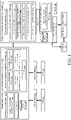
- FIGS. 2A and 2B illustrate a flow diagram showing one example of the operation of architecture 100 in identifying targeted attacks, generating an attacker profile, and controlling system 106 to take remedial action. It is first assumed that malicious activity analysis system 138 obtains malicious activity data indicative of an attempted attack or malicious activity from malicious activity detection system 126 in monitored computing system 102. Obtaining this information is indicated by block 160 in the flow diagram of FIG. 2 .
- the malicious activity data indicates an attempt to gain access to a resource that the attacker is not authorized to access. This is indicated by block 162.
- the malicious activity data may be indicative of an attempt to perform another unauthorized action, or it may represent other attacks as well. This is indicated by blocks 164 and 166.
- Malicious activity security system 138 selects a set of malicious activity or a pattern (or signals representing the malicious activity or pattern) for security actions. This is indicated by block 168.
- Signal enrichment logic 145 then enriches those signals with enrichment properties, which can be used by clustering logic 146. This is indicated by block 161.
- the enrichment properties can include a wide variety of properties, such as target information 163 identified by logic 130, attacker characteristics 165 identified by logic 132, attack characteristics 167 identified by logic 133 and a wide variety of other characteristics 169.
- Clustering logic 146 then identifies and refines clusters by applying filters based on the malicious activity signals and the enrichment properties. This is indicated by block 170. For instance, clustering logic 146 can generate clusters of targets by filtering the malicious activity signals and enrichment properties based on target attributes 163. This is indicated by block 171. The targets may be clustered by filtering based upon the function that the target performs for an organization, such as a tenant. This is indicated by block 172. By way of example, if the targeted user is in a research role, a financial role, etc., and signal enrichment logic has enriched the malicious activity or pattern signals with that information, then they may be filtered based on that information to generate clusters according to that role, or the function that the targets perform.
- the targets may be clustered by filtering based upon the department where the targets work, as indicated by block 174. They may be clustered based upon the physical location of the targets, or in other ways as indicated by block 176. Once the filters are applied and the targets are clustered, the clusters can further be defined into subsets or sub-clusters (or additional clusters can be generated) by applying filters to filter based upon the characteristics of the attack, as indicated by block 178, and based upon the characteristics of the attacker as indicated by block 180.
- the targets when the targets are first filtered so they are clustered based upon the function, department, physical location, etc., of the targets of the attack, this will identify different groups of users that are being targeted.
- the clusters are refined by applying filters to filter based upon the characteristics of the attack (such as payload features in an e-mail, or other characteristics of an attack) this separates the clusters out into different groups of users that are targeted by attacks having different characteristics.
- the initial clusters and the sub-clusters can be further refined by applying filters to filter based upon the characteristics of the attacker. This will indicate whether an attacker having a set of characteristics is preferentially attacking one of the targeted groups or clusters.
- targeted attack identifier 149 determines whether the malicious activity of an attacker or group of attackers, or whether attacks having similar characteristics, preferentially target a target cluster or a set of target clusters. This is indicated by block 182. If so, then the malicious activity can be identified as a targeted attack. This is indicated by block 184.
- Prevalence filtering logic 148 can also apply time filters to identify a prevalence of the malicious activity broadly, as indicated by block 186.
- prevalence is represented by a number of attacks relative to a number of other attacks in the group being considered. For instance, assume that a malicious activity pattern has been identified as an attack.
- Prevalence filtering logic 148 can apply filters to determine whether the attack has been launched a relatively high number of times, relative to other attacks in a particular category. This is indicated by block 186. For instance, it can identify the prevalence of an attack on monitored computing system 102 across a country 181 (or other geographic region), across an industry 183 or across another broad prevalence category185.
- Logic 148 can apply a concentration filter to identify whether there is a concentration of the malicious activity on a specific tenant, a cluster of tenants, or another cluster of targets.
- Targeted attack identifier 149 determines whether the malicious activity has a relatively low prevalence broadly but a relatively high concentration on a specific tenant or other target cluster. This is indicated by block 188. If so, then the malicious activity is identified as a targeted attack as well. This is indicated by block 190.
- processing skips to block 194 where it is determined whether there are any additional malicious activities or patterns to consider by target attack identification system 104. If so, processing reverts to block 160.
- system 104 controls attacker profile generator logic 150 to start building an attacker profile based upon the attacker characteristics identified by attacker characteristic identifier logic 132. Building an attacker profile is indicated by block 196 in the flow diagram of FIG. 2 .
- system 104 controls attack surfacing logic 142 to generate and surface an interactive indication of the targeted attack.
- control signal generator logic 143 can generate control signals to control user interface mechanism 147 to surface an interactive display that may be surfaced with drill actuators that can be used to drill up into less detailed or more general information about the attack, the attacker, the targets, other attacks, etc. It may also have one or more actuators to drill down into more detailed information about the targeted attack, about the attacker, about the targets, etc.
- system 104, or user 116 can then control remedial action system 106 in order to take remedial action.
- control signal generator logic 143 can generate signals to control remedial action system 106 to automatically take action. This is indicated by block 200.
- the remedial action can be taken (automatically or by user 116) to stop or inhibit the targeted attack from continuing, to inhibit future targeted attacks by this attacker or a similar attacker, or an attacker using similar attack characteristics, or to perform other remedial actions.
- the present system improves a computing system by greatly enhancing the security of the computing system by identifying targeted attacks which may otherwise go unidentified. It applies various filter criteria to identify target clusters and concentrations of relatively low prevalence attacks on small groups of targets. It then generates control signals to control output logic to generate and surface an output indicative of the targeted attacks so that remedial action can be taken.
- systems, components and/or logic can be comprised of hardware items (such as processors and associated memory, or other processing components, some of which are described below) that perform the functions associated with those systems, components and/or logic.
- the systems, components and/or logic can be comprised of software that is loaded into a memory and is subsequently executed by a processor or server, or other computing component, as described below.
- the systems, components and/or logic can also be comprised of different combinations of hardware, software, firmware, etc., some examples of which are described below.
- processors and servers include computer processors with associated memory and timing circuitry, not separately shown. They are functional parts of the systems or devices to which they belong and are activated by, and facilitate the functionality of the other components or items in those systems.
- the user actuatable input mechanisms can be text boxes, check boxes, icons, links, drop-down menus, search boxes, etc. They can also be actuated in a wide variety of different ways. For instance, they can be actuated using a point and click device (such as a track ball or mouse). They can be actuated using hardware buttons, switches, a joystick or keyboard, thumb switches or thumb pads, etc. They can also be actuated using a virtual keyboard or other virtual actuators. In addition, where the screen on which they are displayed is a touch sensitive screen, they can be actuated using touch gestures. Also, where the device that displays them has speech recognition components, they can be actuated using speech commands.
- a number of data stores have also been discussed. It will be noted they can each be broken into multiple data stores. All can be local to the systems accessing them, all can be remote, or some can be local while others are remote. All of these configurations are contemplated herein.
- the figures show a number of blocks with functionality ascribed to each block. It will be noted that fewer blocks can be used so the functionality is performed by fewer components. Also, more blocks can be used with the functionality distributed among more components.
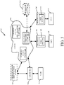
- FIG. 3 is a block diagram of architecture 100, shown in FIG. 1 , except that its elements are disposed in a cloud computing architecture 500.
- Cloud computing provides computation, software, data access, and storage services that do not require end-user knowledge of the physical location or configuration of the system that delivers the services.
- cloud computing delivers the services over a wide area network, such as the internet, using appropriate protocols.
- cloud computing providers deliver applications over a wide area network and they can be accessed through a web browser or any other computing component.
- Software or components of architecture 100 as well as the corresponding data can be stored on servers at a remote location.
- the computing resources in a cloud computing environment can be consolidated at a remote data center location or they can be dispersed.
- Cloud computing infrastructures can deliver services through shared data centers, even though they appear as a single point of access for the user.
- the components and functions described herein can be provided from a service provider at a remote location using a cloud computing architecture.
- they can be provided from a conventional server, or they can be installed on client devices directly, or in other ways.
- Cloud computing both public and private provides substantially seamless pooling of resources, as well as a reduced need to manage and configure underlying hardware infrastructure.
- a public cloud is managed by a vendor and typically supports multiple consumers using the same infrastructure. Also, a public cloud, as opposed to a private cloud, can free up the end users from managing the hardware.
- a private cloud may be managed by the organization itself and the infrastructure is typically not shared with other organizations. The organization still maintains the hardware to some extent, such as installations and repairs, etc.
- FIG. 3 specifically shows that monitored computing system 102, targeted attack identification system 104 and remedial action system 106 can be located in cloud 502 (which can be public, private, or a combination where portions are public while others are private). Therefore, users 108, 112, 114, and 116 use user devices 504, 506 and 508 to access those systems through cloud 502.
- cloud 502 which can be public, private, or a combination where portions are public while others are private. Therefore, users 108, 112, 114, and 116 use user devices 504, 506 and 508 to access those systems through cloud 502.
- FIG. 3 also depicts another example of a cloud architecture.
- FIG. 3 shows that it is also contemplated that some elements of architecture 100 can be disposed in cloud 502 while others are not.
- data stores 120, 140 can be disposed outside of cloud 502, and accessed through cloud 502.
- targeted attack identification system 104 (or other items) can be outside of cloud 502. Regardless of where they are located, they can be accessed directly by the appropriate user devices, through a network (either a wide area network or a local area network), they can be hosted at a remote site by a service, or they can be provided as a service through a cloud or accessed by a connection service that resides in the cloud. All of these architectures are contemplated herein.
- architecture 100 can be disposed on a wide variety of different devices. Some of those devices include servers, desktop computers, laptop computers, tablet computers, or other mobile devices, such as palm top computers, cell phones, smart phones, multimedia players, personal digital assistants, etc.
- FIG. 4 is a simplified block diagram of one illustrative example of a handheld or mobile computing device that can be used as a user's or client's hand held device 16, in which the present system (or parts of it) can be deployed.
- FIGS. 5-6 are examples of handheld or mobile devices.
- FIG. 4 provides a general block diagram of the components of a client device 16 that can run components architecture 100 or user devices 504, 506 and 508 or that interacts with architecture 100, or both.
- a communications link 13 is provided that allows the handheld device to communicate with other computing devices and under some embodiments provides a channel for receiving information automatically, such as by scanning.
- Examples of communications link 13 include an infrared port, a serial/USB port, a cable network port such as an Ethernet port, and a wireless network port allowing communication though one or more communication protocols including General Packet Radio Service (GPRS), LTE, HSPA, HSPA+ and other 3G and 4G radio protocols, 1Xrtt, and Short Message Service, which are wireless services used to provide cellular access to a network, as well as Wi-Fi protocols, and Bluetooth protocol, which provide local wireless connections to networks.
- GPRS General Packet Radio Service
- LTE Long Term Evolution
- HSPA High Speed Packet Access
- HSPA+ High Speed Packet Access Plus
- 3G and 4G radio protocols 3G and 4G radio protocols
- 1Xrtt 3G and 4G radio protocols
- Short Message Service Short Message Service
- SD card interface 15 and communication links 13 communicate with a processor 17 (which can also embody processors or servers from other FIGS.) along a bus 19 that is also connected to memory 21 and input/output (I/O) components 23, as well as clock 25 and location system 27.
- processor 17 which can also embody processors or servers from other FIGS.
- bus 19 that is also connected to memory 21 and input/output (I/O) components 23, as well as clock 25 and location system 27.
- I/O components 23 are provided to facilitate input and output operations.
- I/O components 23 for various examples of the device 16 can include input components such as buttons, touch sensors, multi-touch sensors, optical or video sensors, voice sensors, touch screens, proximity sensors, microphones, tilt sensors, and gravity switches and output components such as a display device, a speaker, and or a printer port.
- Other I/O components 23 can be used as well.
- Clock 25 illustratively comprises a real time clock component that outputs a time and date. It can also, illustratively, provide timing functions for processor 17.
- Location system 27 illustratively includes a component that outputs a current geographical location of device 16. This can include, for instance, a global positioning system (GPS) receiver, a LORAN system, a dead reckoning system, a cellular triangulation system, or other positioning system. It can also include, for example, mapping software or navigation software that generates desired maps, navigation routes and other geographic functions.
- GPS global positioning system
- Memory 21 stores operating system 29, network settings 31, applications 33, application configuration settings 35, data store 37, communication drivers 39, and communication configuration settings 41.
- Memory 21 can include all types of tangible volatile and non-volatile computer-readable memory devices. It can also include computer storage media (described below).
- Memory 21 stores computer readable instructions that, when executed by processor 17, cause the processor to perform computer-implemented steps or functions according to the instructions.
- device 16 can have a client system 24 which can run various applications or embody parts or all of architecture 100. Processor 17 can be activated by other components to facilitate their functionality as well.
- Examples of the network settings 31 include things such as proxy information, Internet connection information, and mappings.
- Application configuration settings 35 include settings that tailor the application for a specific enterprise or user.
- Communication configuration settings 41 provide parameters for communicating with other computers and include items such as GPRS parameters, SMS parameters, connection user names and passwords.
- Applications 33 can be applications that have previously been stored on the device 16 or applications that are installed during use, although these can be part of operating system 29, or hosted external to device 16, as well.
- FIG. 5 shows one example in which device 16 is a tablet computer 600.
- computer 600 is shown with user interface display screen 602.
- Screen 602 can be a touch screen (so touch gestures from a user's finger can be used to interact with the application) or a pen-enabled interface that receives inputs from a pen or stylus. It can also use an on-screen virtual keyboard. Of course, it might also be attached to a keyboard or other user input device through a suitable attachment mechanism, such as a wireless link or USB port, for instance.
- Computer 600 can also illustratively receive voice inputs as well.
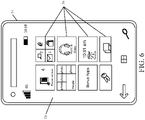
- FIG. 6 shows that the device can be a smart phone 71.
- Smart phone 71 has a touch sensitive display 73 that displays icons or tiles or other user input mechanisms 75. Mechanisms 75 can be used by a user to run applications, make calls, perform data transfer operations, etc.
- smart phone 71 is built on a mobile operating system and offers more advanced computing capability and connectivity than a feature phone.
- FIG. 7 is one example of a computing environment in which architecture 100, or parts of it, (for example) can be deployed.
- an example system for implementing some embodiments includes a general-purpose computing device in the form of a computer 810.
- Components of computer 810 may include, but are not limited to, a processing unit 820 (which can comprise processors or servers from previous FIGS.), a system memory 830, and a system bus 821 that couples various system components including the system memory to the processing unit 820.
- the system bus 821 may be any of several types of bus structures including a memory bus or memory controller, a peripheral bus, and a local bus using any of a variety of bus architectures.
- such architectures include Industry Standard Architecture (ISA) bus, Micro Channel Architecture (MCA) bus, Enhanced ISA (EISA) bus, Video Electronics Standards Association (VESA) local bus, and Peripheral Component Interconnect (PCI) bus also known as Mezzanine bus.
- ISA Industry Standard Architecture
- MCA Micro Channel Architecture
- EISA Enhanced ISA
- VESA Video Electronics Standards Association
- PCI Peripheral Component Interconnect
- Computer 810 typically includes a variety of computer readable media.
- Computer readable media can be any available media that can be accessed by computer 810 and includes both volatile and nonvolatile media, removable and non-removable media.
- Computer readable media may comprise computer storage media and communication media.
- Computer storage media is different from, and does not include, a modulated data signal or carrier wave. It includes hardware storage media including both volatile and nonvolatile, removable and non-removable media implemented in any method or technology for storage of information such as computer readable instructions, data structures, program modules or other data.
- Computer storage media includes, but is not limited to, RAM, ROM, EEPROM, flash memory or other memory technology, CD-ROM, digital versatile disks (DVD) or other optical disk storage, magnetic cassettes, magnetic tape, magnetic disk storage or other magnetic storage devices, or any other medium which can be used to store the desired information and which can be accessed by computer 810.
- Communication media typically embodies computer readable instructions, data structures, program modules or other data in a transport mechanism and includes any information delivery media.
- modulated data signal means a signal that has one or more of its characteristics set or changed in such a manner as to encode information in the signal.
- communication media includes wired media such as a wired network or direct-wired connection, and wireless media such as acoustic, RF, infrared and other wireless media. Combinations of any of the above should also be included within the scope of computer readable media.
- the system memory 830 includes computer storage media in the form of volatile and/or nonvolatile memory such as read only memory (ROM) 831 and random access memory (RAM) 832.
- ROM read only memory
- RAM random access memory
- BIOS basic input/output system 833
- RAM 832 typically contains data and/or program modules that are immediately accessible to and/or presently being operated on by processing unit 820.
- FIG. 7 illustrates operating system 834, application programs 835, other program modules 836, and program data 837.
- the computer 810 may also include other removable/non-removable volatile/nonvolatile computer storage media.
- FIG. 7 illustrates a hard disk drive 841 that reads from or writes to non-removable, nonvolatile magnetic media, and an optical disk drive 855 that reads from or writes to a removable, nonvolatile optical disk 856 such as a CD ROM or other optical media.
- Other removable/non-removable, volatile/nonvolatile computer storage media that can be used in the exemplary operating environment include, but are not limited to, magnetic tape cassettes, flash memory cards, digital versatile disks, digital video tape, solid state RAM, solid state ROM, and the like.
- the hard disk drive 841 is typically connected to the system bus 821 through a non-removable memory interface such as interface 840, and optical disk drive 855 are typically connected to the system bus 821 by a removable memory interface, such as interface 850.
- the functionality described herein can be performed, at least in part, by one or more hardware logic components.
- illustrative types of hardware logic components include Field-programmable Gate Arrays (FPGAs), Program-specific Integrated Circuits (ASICs), Program-specific Standard Products (ASSPs), System-on-a-chip systems (SOCs), Complex Programmable Logic Devices (CPLDs), etc.
- hard disk drive 841 is illustrated as storing operating system 844, application programs 845, other program modules 846, and program data 847. Note that these components can either be the same as or different from operating system 834, application programs 835, other program modules 836, and program data 837. Operating system 844, application programs 845, other program modules 846, and program data 847 are given different numbers here to illustrate that, at a minimum, they are different copies.
- a user may enter commands and information into the computer 810 through input devices such as a keyboard 862, a microphone 863, and a pointing device 861, such as a mouse, trackball or touch pad.
- Other input devices may include a joystick, game pad, satellite dish, scanner, or the like.
- These and other input devices are often connected to the processing unit 820 through a user input interface 860 that is coupled to the system bus, but may be connected by other interface and bus structures, such as a parallel port, game port or a universal serial bus (USB).
- a visual display 891 or other type of display device is also connected to the system bus 821 via an interface, such as a video interface 890.
- computers may also include other peripheral output devices such as speakers 897 and printer 896, which may be connected through an output peripheral interface 895.
- the computer 810 is operated in a networked environment using logical connections to one or more remote computers, such as a remote computer 880.
- the remote computer 880 may be a personal computer, a hand-held device, a server, a router, a network PC, a peer device or other common network node, and typically includes many or all of the elements described above relative to the computer 810.
- the logical connections depicted in FIG. 7 include a local area network (LAN) 871 and a wide area network (WAN) 873, but may also include other networks.
- LAN local area network
- WAN wide area network
- Such networking environments are commonplace in offices, enterprise-wide computer networks, intranets and the Internet.
- the computer 810 When used in a LAN networking environment, the computer 810 is connected to the LAN 871 through a network interface or adapter 870. When used in a WAN networking environment, the computer 810 typically includes a modem 872 or other means for establishing communications over the WAN 873, such as the Internet.
- the modem 872 which may be internal or external, may be connected to the system bus 821 via the user input interface 860, or other appropriate mechanism.
- program modules depicted relative to the computer 810, or portions thereof may be stored in the remote memory storage device.
- FIG. 7 illustrates remote application programs 885 as residing on remote computer 880. It will be appreciated that the network connections shown are exemplary and other means of establishing a communications link between the computers may be used.
Landscapes
- Engineering & Computer Science (AREA)
- Computer Security & Cryptography (AREA)
- Computer Hardware Design (AREA)
- General Engineering & Computer Science (AREA)
- Theoretical Computer Science (AREA)
- Software Systems (AREA)
- Computing Systems (AREA)
- Computer Networks & Wireless Communication (AREA)
- Signal Processing (AREA)
- Physics & Mathematics (AREA)
- General Physics & Mathematics (AREA)
- Health & Medical Sciences (AREA)
- General Health & Medical Sciences (AREA)
- Virology (AREA)
- Data Exchanges In Wide-Area Networks (AREA)
- Computer And Data Communications (AREA)
- Information Transfer Between Computers (AREA)
Applications Claiming Priority (4)
| Application Number | Priority Date | Filing Date | Title |
|---|---|---|---|
| US201762561966P | 2017-09-22 | 2017-09-22 | |
| US15/874,983 US10715545B2 (en) | 2017-09-22 | 2018-01-19 | Detection and identification of targeted attacks on a computing system |
| EP18742640.8A EP3685295B1 (fr) | 2017-09-22 | 2018-06-25 | Détection et identification d'attaques ciblées d'un système informatique |
| PCT/US2018/039220 WO2019060014A1 (fr) | 2017-09-22 | 2018-06-25 | Détection et identification d'attaques ciblées d'un système informatique |
Related Parent Applications (2)
| Application Number | Title | Priority Date | Filing Date |
|---|---|---|---|
| EP18742640.8A Division-Into EP3685295B1 (fr) | 2017-09-22 | 2018-06-25 | Détection et identification d'attaques ciblées d'un système informatique |
| EP18742640.8A Division EP3685295B1 (fr) | 2017-09-22 | 2018-06-25 | Détection et identification d'attaques ciblées d'un système informatique |
Publications (2)
| Publication Number | Publication Date |
|---|---|
| EP4006762A1 true EP4006762A1 (fr) | 2022-06-01 |
| EP4006762B1 EP4006762B1 (fr) | 2023-03-29 |
Family
ID=65808250
Family Applications (2)
| Application Number | Title | Priority Date | Filing Date |
|---|---|---|---|
| EP22153459.7A Active EP4006762B1 (fr) | 2017-09-22 | 2018-06-25 | Détection et identification d'attaques ciblées d'un système informatique |
| EP18742640.8A Active EP3685295B1 (fr) | 2017-09-22 | 2018-06-25 | Détection et identification d'attaques ciblées d'un système informatique |
Family Applications After (1)
| Application Number | Title | Priority Date | Filing Date |
|---|---|---|---|
| EP18742640.8A Active EP3685295B1 (fr) | 2017-09-22 | 2018-06-25 | Détection et identification d'attaques ciblées d'un système informatique |
Country Status (4)
| Country | Link |
|---|---|
| US (2) | US10715545B2 (fr) |
| EP (2) | EP4006762B1 (fr) |
| CN (2) | CN117424734A (fr) |
| WO (1) | WO2019060014A1 (fr) |
Families Citing this family (30)
| Publication number | Priority date | Publication date | Assignee | Title |
|---|---|---|---|---|
| US11010233B1 (en) | 2018-01-18 | 2021-05-18 | Pure Storage, Inc | Hardware-based system monitoring |
| US10834111B2 (en) * | 2018-01-29 | 2020-11-10 | International Business Machines Corporation | Method and system for email phishing attempts identification and notification through organizational cognitive solutions |
| CN120632864A (zh) * | 2019-11-03 | 2025-09-12 | 微软技术许可有限责任公司 | 用于对抗网络攻击的攻击活动智能和可视化 |
| US12050689B2 (en) | 2019-11-22 | 2024-07-30 | Pure Storage, Inc. | Host anomaly-based generation of snapshots |
| US12050683B2 (en) * | 2019-11-22 | 2024-07-30 | Pure Storage, Inc. | Selective control of a data synchronization setting of a storage system based on a possible ransomware attack against the storage system |
| US11645162B2 (en) | 2019-11-22 | 2023-05-09 | Pure Storage, Inc. | Recovery point determination for data restoration in a storage system |
| US12204657B2 (en) | 2019-11-22 | 2025-01-21 | Pure Storage, Inc. | Similar block detection-based detection of a ransomware attack |
| US11341236B2 (en) | 2019-11-22 | 2022-05-24 | Pure Storage, Inc. | Traffic-based detection of a security threat to a storage system |
| US11687418B2 (en) | 2019-11-22 | 2023-06-27 | Pure Storage, Inc. | Automatic generation of recovery plans specific to individual storage elements |
| US11500788B2 (en) | 2019-11-22 | 2022-11-15 | Pure Storage, Inc. | Logical address based authorization of operations with respect to a storage system |
| US12079356B2 (en) | 2019-11-22 | 2024-09-03 | Pure Storage, Inc. | Measurement interval anomaly detection-based generation of snapshots |
| US11675898B2 (en) | 2019-11-22 | 2023-06-13 | Pure Storage, Inc. | Recovery dataset management for security threat monitoring |
| US12079333B2 (en) | 2019-11-22 | 2024-09-03 | Pure Storage, Inc. | Independent security threat detection and remediation by storage systems in a synchronous replication arrangement |
| US12067118B2 (en) | 2019-11-22 | 2024-08-20 | Pure Storage, Inc. | Detection of writing to a non-header portion of a file as an indicator of a possible ransomware attack against a storage system |
| US11651075B2 (en) | 2019-11-22 | 2023-05-16 | Pure Storage, Inc. | Extensible attack monitoring by a storage system |
| US12411962B2 (en) | 2019-11-22 | 2025-09-09 | Pure Storage, Inc. | Managed run-time environment-based detection of a ransomware attack |
| US12561428B2 (en) | 2019-11-22 | 2026-02-24 | Pure Storage, Inc. | Remote analysis of potentially corrupt data written to a storage system |
| US11625481B2 (en) | 2019-11-22 | 2023-04-11 | Pure Storage, Inc. | Selective throttling of operations potentially related to a security threat to a storage system |
| US11615185B2 (en) | 2019-11-22 | 2023-03-28 | Pure Storage, Inc. | Multi-layer security threat detection for a storage system |
| US11755751B2 (en) | 2019-11-22 | 2023-09-12 | Pure Storage, Inc. | Modify access restrictions in response to a possible attack against data stored by a storage system |
| US12153670B2 (en) | 2019-11-22 | 2024-11-26 | Pure Storage, Inc. | Host-driven threat detection-based protection of storage elements within a storage system |
| US11657155B2 (en) | 2019-11-22 | 2023-05-23 | Pure Storage, Inc | Snapshot delta metric based determination of a possible ransomware attack against data maintained by a storage system |
| US11941116B2 (en) | 2019-11-22 | 2024-03-26 | Pure Storage, Inc. | Ransomware-based data protection parameter modification |
| US11720692B2 (en) | 2019-11-22 | 2023-08-08 | Pure Storage, Inc. | Hardware token based management of recovery datasets for a storage system |
| US12248566B2 (en) | 2019-11-22 | 2025-03-11 | Pure Storage, Inc. | Snapshot deletion pattern-based determination of ransomware attack against data maintained by a storage system |
| US11720714B2 (en) | 2019-11-22 | 2023-08-08 | Pure Storage, Inc. | Inter-I/O relationship based detection of a security threat to a storage system |
| US11520907B1 (en) | 2019-11-22 | 2022-12-06 | Pure Storage, Inc. | Storage system snapshot retention based on encrypted data |
| US12079502B2 (en) | 2019-11-22 | 2024-09-03 | Pure Storage, Inc. | Storage element attribute-based determination of a data protection policy for use within a storage system |
| US12506777B2 (en) * | 2023-04-19 | 2025-12-23 | Bank Of America Corporation | Anti-phishing security |
| US20250165601A1 (en) * | 2023-11-16 | 2025-05-22 | Wells Fargo Bank, N.A. | Machine learning techniques to generate negotiation data during computing system attacks |
Citations (4)
| Publication number | Priority date | Publication date | Assignee | Title |
|---|---|---|---|---|
| US20160103992A1 (en) * | 2014-10-14 | 2016-04-14 | Symantec Corporation | Systems and methods for classifying security events as targeted attacks |
| US20160164891A1 (en) * | 2014-12-03 | 2016-06-09 | Phantom Cyber Corporation | Classifying kill-chains for security incidents |
| EP3079337A1 (fr) * | 2015-04-09 | 2016-10-12 | Accenture Global Services Limited | Corrélation d'événements à travers des opérations hétérogènes |
| EP3179696A1 (fr) * | 2015-12-09 | 2017-06-14 | Accenture Global Solutions Limited | Système de sécurité connecté |
Family Cites Families (24)
| Publication number | Priority date | Publication date | Assignee | Title |
|---|---|---|---|---|
| US9009828B1 (en) * | 2007-09-28 | 2015-04-14 | Dell SecureWorks, Inc. | System and method for identification and blocking of unwanted network traffic |
| US9075993B2 (en) * | 2011-01-24 | 2015-07-07 | Mcafee, Inc. | System and method for selectively grouping and managing program files |
| US9710644B2 (en) * | 2012-02-01 | 2017-07-18 | Servicenow, Inc. | Techniques for sharing network security event information |
| US9456001B2 (en) * | 2013-01-31 | 2016-09-27 | Hewlett Packard Enterprise Development Lp | Attack notification |
| GB2520987B (en) * | 2013-12-06 | 2016-06-01 | Cyberlytic Ltd | Using fuzzy logic to assign a risk level profile to a potential cyber threat |
| US9753796B2 (en) * | 2013-12-06 | 2017-09-05 | Lookout, Inc. | Distributed monitoring, evaluation, and response for multiple devices |
| US9596264B2 (en) * | 2014-02-18 | 2017-03-14 | Proofpoint, Inc. | Targeted attack protection using predictive sandboxing |
| US8997226B1 (en) * | 2014-04-17 | 2015-03-31 | Shape Security, Inc. | Detection of client-side malware activity |
| US9185119B1 (en) * | 2014-05-08 | 2015-11-10 | Symantec Corporation | Systems and methods for detecting malware using file clustering |
| US9386031B2 (en) * | 2014-09-12 | 2016-07-05 | AO Kaspersky Lab | System and method for detection of targeted attacks |
| US9571519B2 (en) * | 2014-09-29 | 2017-02-14 | Juniper Networks, Inc. | Targeted attack discovery |
| US9591007B2 (en) * | 2014-11-06 | 2017-03-07 | International Business Machines Corporation | Detection of beaconing behavior in network traffic |
| US10104097B1 (en) * | 2014-12-12 | 2018-10-16 | Symantec Corporation | Systems and methods for preventing targeted malware attacks |
| US9928369B2 (en) * | 2015-02-09 | 2018-03-27 | Cisco Technologies, Inc. | Information technology vulnerability assessment |
| JP6690646B2 (ja) * | 2015-06-26 | 2020-04-28 | 日本電気株式会社 | 情報処理装置、情報処理システム、情報処理方法、及び、プログラム |
| US9774619B1 (en) * | 2015-09-24 | 2017-09-26 | Amazon Technologies, Inc. | Mitigating network attacks |
| EP3387814B1 (fr) * | 2015-12-11 | 2024-02-14 | ServiceNow, Inc. | Évaluation de la menace du réseau informatique |
| CN108351939A (zh) * | 2015-12-14 | 2018-07-31 | 三菱电机株式会社 | 信息处理装置、信息处理方法和信息处理程序 |
| EP3433995B1 (fr) * | 2016-03-24 | 2023-12-13 | Carbon Black, Inc. | Systèmes et techniques pour guider une réponse à un incident de cybersecurité |
| US10178109B1 (en) * | 2016-03-31 | 2019-01-08 | Symantec Corporation | Discovery of groupings of security alert types and corresponding complex multipart attacks, from analysis of massive security telemetry |
| US10121000B1 (en) * | 2016-06-28 | 2018-11-06 | Fireeye, Inc. | System and method to detect premium attacks on electronic networks and electronic devices |
| US10237300B2 (en) * | 2017-04-06 | 2019-03-19 | Microsoft Technology Licensing, Llc | System and method for detecting directed cyber-attacks targeting a particular set of cloud based machines |
| US10452841B1 (en) * | 2017-05-01 | 2019-10-22 | Symantec Corporation | Modeling malicious behavior that occurs in the absence of users |
| CN110637320A (zh) * | 2017-05-25 | 2019-12-31 | 三菱电机株式会社 | 评价装置、评价方法以及评价程序 |
-
2018
- 2018-01-19 US US15/874,983 patent/US10715545B2/en active Active
- 2018-06-25 EP EP22153459.7A patent/EP4006762B1/fr active Active
- 2018-06-25 CN CN202311385040.8A patent/CN117424734A/zh active Pending
- 2018-06-25 CN CN201880060963.7A patent/CN111108496B/zh active Active
- 2018-06-25 EP EP18742640.8A patent/EP3685295B1/fr active Active
- 2018-06-25 WO PCT/US2018/039220 patent/WO2019060014A1/fr not_active Ceased
-
2020
- 2020-06-08 US US16/895,608 patent/US11025665B2/en active Active
Patent Citations (4)
| Publication number | Priority date | Publication date | Assignee | Title |
|---|---|---|---|---|
| US20160103992A1 (en) * | 2014-10-14 | 2016-04-14 | Symantec Corporation | Systems and methods for classifying security events as targeted attacks |
| US20160164891A1 (en) * | 2014-12-03 | 2016-06-09 | Phantom Cyber Corporation | Classifying kill-chains for security incidents |
| EP3079337A1 (fr) * | 2015-04-09 | 2016-10-12 | Accenture Global Services Limited | Corrélation d'événements à travers des opérations hétérogènes |
| EP3179696A1 (fr) * | 2015-12-09 | 2017-06-14 | Accenture Global Solutions Limited | Système de sécurité connecté |
Also Published As
| Publication number | Publication date |
|---|---|
| EP3685295A1 (fr) | 2020-07-29 |
| US11025665B2 (en) | 2021-06-01 |
| EP3685295B1 (fr) | 2022-03-16 |
| US20190098040A1 (en) | 2019-03-28 |
| US10715545B2 (en) | 2020-07-14 |
| CN111108496B (zh) | 2023-11-03 |
| EP4006762B1 (fr) | 2023-03-29 |
| US20200304538A1 (en) | 2020-09-24 |
| CN111108496A (zh) | 2020-05-05 |
| CN117424734A (zh) | 2024-01-19 |
| WO2019060014A1 (fr) | 2019-03-28 |
Similar Documents
| Publication | Publication Date | Title |
|---|---|---|
| US11025665B2 (en) | Detection and identification of targeted attacks on a computing system | |
| US12013933B2 (en) | Enhancing security using anomaly detection | |
| US11916897B2 (en) | Isolating networks and credentials using on-demand port forwarding | |
| US11856009B2 (en) | Configurable cyber-attack trackers | |
| US20170364692A1 (en) | Electronic file sharing link granularity | |
| WO2017040226A1 (fr) | Contrôle d'accès à un enregistrement sécurisé dans un système informatique | |
| AU2016258555A1 (en) | Automatically relating content to people | |
| US10530860B2 (en) | Single multi-instance tenant computing system | |
| US11334420B2 (en) | Remote recovery and support using chat messages | |
| US10104117B2 (en) | Identifying user behavior in a distributed computing system | |
| US20150207768A1 (en) | Deriving atomic communication threads from independently addressable messages | |
| US9954863B2 (en) | Computing system record security architecture | |
| US11122104B2 (en) | Surfacing sharing attributes of a link proximate a browser address bar |
Legal Events
| Date | Code | Title | Description |
|---|---|---|---|
| PUAI | Public reference made under article 153(3) epc to a published international application that has entered the european phase |
Free format text: ORIGINAL CODE: 0009012 |
|
| STAA | Information on the status of an ep patent application or granted ep patent |
Free format text: STATUS: REQUEST FOR EXAMINATION WAS MADE |
|
| 17P | Request for examination filed |
Effective date: 20220126 |
|
| AC | Divisional application: reference to earlier application |
Ref document number: 3685295 Country of ref document: EP Kind code of ref document: P |
|
| AK | Designated contracting states |
Kind code of ref document: A1 Designated state(s): AL AT BE BG CH CY CZ DE DK EE ES FI FR GB GR HR HU IE IS IT LI LT LU LV MC MK MT NL NO PL PT RO RS SE SI SK SM TR |
|
| RIC1 | Information provided on ipc code assigned before grant |
Ipc: H04L 9/40 20220101ALI20220914BHEP Ipc: G06F 21/57 20130101ALI20220914BHEP Ipc: G06F 21/56 20130101ALI20220914BHEP Ipc: G06F 21/55 20130101AFI20220914BHEP |
|
| GRAP | Despatch of communication of intention to grant a patent |
Free format text: ORIGINAL CODE: EPIDOSNIGR1 |
|
| STAA | Information on the status of an ep patent application or granted ep patent |
Free format text: STATUS: GRANT OF PATENT IS INTENDED |
|
| INTG | Intention to grant announced |
Effective date: 20221107 |
|
| GRAS | Grant fee paid |
Free format text: ORIGINAL CODE: EPIDOSNIGR3 |
|
| GRAA | (expected) grant |
Free format text: ORIGINAL CODE: 0009210 |
|
| STAA | Information on the status of an ep patent application or granted ep patent |
Free format text: STATUS: THE PATENT HAS BEEN GRANTED |
|
| AC | Divisional application: reference to earlier application |
Ref document number: 3685295 Country of ref document: EP Kind code of ref document: P |
|
| AK | Designated contracting states |
Kind code of ref document: B1 Designated state(s): AL AT BE BG CH CY CZ DE DK EE ES FI FR GB GR HR HU IE IS IT LI LT LU LV MC MK MT NL NO PL PT RO RS SE SI SK SM TR |
|
| REG | Reference to a national code |
Ref country code: CH Ref legal event code: EP |
|
| REG | Reference to a national code |
Ref country code: DE Ref legal event code: R096 Ref document number: 602018047943 Country of ref document: DE |
|
| REG | Reference to a national code |
Ref country code: AT Ref legal event code: REF Ref document number: 1557185 Country of ref document: AT Kind code of ref document: T Effective date: 20230415 |
|
| REG | Reference to a national code |
Ref country code: IE Ref legal event code: FG4D |
|
| REG | Reference to a national code |
Ref country code: NL Ref legal event code: FP |
|
| P01 | Opt-out of the competence of the unified patent court (upc) registered |
Effective date: 20230505 |
|
| REG | Reference to a national code |
Ref country code: LT Ref legal event code: MG9D |
|
| PG25 | Lapsed in a contracting state [announced via postgrant information from national office to epo] |
Ref country code: RS Free format text: LAPSE BECAUSE OF FAILURE TO SUBMIT A TRANSLATION OF THE DESCRIPTION OR TO PAY THE FEE WITHIN THE PRESCRIBED TIME-LIMIT Effective date: 20230329 Ref country code: NO Free format text: LAPSE BECAUSE OF FAILURE TO SUBMIT A TRANSLATION OF THE DESCRIPTION OR TO PAY THE FEE WITHIN THE PRESCRIBED TIME-LIMIT Effective date: 20230629 Ref country code: LV Free format text: LAPSE BECAUSE OF FAILURE TO SUBMIT A TRANSLATION OF THE DESCRIPTION OR TO PAY THE FEE WITHIN THE PRESCRIBED TIME-LIMIT Effective date: 20230329 Ref country code: LT Free format text: LAPSE BECAUSE OF FAILURE TO SUBMIT A TRANSLATION OF THE DESCRIPTION OR TO PAY THE FEE WITHIN THE PRESCRIBED TIME-LIMIT Effective date: 20230329 Ref country code: HR Free format text: LAPSE BECAUSE OF FAILURE TO SUBMIT A TRANSLATION OF THE DESCRIPTION OR TO PAY THE FEE WITHIN THE PRESCRIBED TIME-LIMIT Effective date: 20230329 |
|
| REG | Reference to a national code |
Ref country code: AT Ref legal event code: MK05 Ref document number: 1557185 Country of ref document: AT Kind code of ref document: T Effective date: 20230329 |
|
| PG25 | Lapsed in a contracting state [announced via postgrant information from national office to epo] |
Ref country code: SE Free format text: LAPSE BECAUSE OF FAILURE TO SUBMIT A TRANSLATION OF THE DESCRIPTION OR TO PAY THE FEE WITHIN THE PRESCRIBED TIME-LIMIT Effective date: 20230329 Ref country code: GR Free format text: LAPSE BECAUSE OF FAILURE TO SUBMIT A TRANSLATION OF THE DESCRIPTION OR TO PAY THE FEE WITHIN THE PRESCRIBED TIME-LIMIT Effective date: 20230630 Ref country code: FI Free format text: LAPSE BECAUSE OF FAILURE TO SUBMIT A TRANSLATION OF THE DESCRIPTION OR TO PAY THE FEE WITHIN THE PRESCRIBED TIME-LIMIT Effective date: 20230329 |
|
| PG25 | Lapsed in a contracting state [announced via postgrant information from national office to epo] |
Ref country code: SM Free format text: LAPSE BECAUSE OF FAILURE TO SUBMIT A TRANSLATION OF THE DESCRIPTION OR TO PAY THE FEE WITHIN THE PRESCRIBED TIME-LIMIT Effective date: 20230329 Ref country code: RO Free format text: LAPSE BECAUSE OF FAILURE TO SUBMIT A TRANSLATION OF THE DESCRIPTION OR TO PAY THE FEE WITHIN THE PRESCRIBED TIME-LIMIT Effective date: 20230329 Ref country code: PT Free format text: LAPSE BECAUSE OF FAILURE TO SUBMIT A TRANSLATION OF THE DESCRIPTION OR TO PAY THE FEE WITHIN THE PRESCRIBED TIME-LIMIT Effective date: 20230731 Ref country code: ES Free format text: LAPSE BECAUSE OF FAILURE TO SUBMIT A TRANSLATION OF THE DESCRIPTION OR TO PAY THE FEE WITHIN THE PRESCRIBED TIME-LIMIT Effective date: 20230329 Ref country code: EE Free format text: LAPSE BECAUSE OF FAILURE TO SUBMIT A TRANSLATION OF THE DESCRIPTION OR TO PAY THE FEE WITHIN THE PRESCRIBED TIME-LIMIT Effective date: 20230329 Ref country code: AT Free format text: LAPSE BECAUSE OF FAILURE TO SUBMIT A TRANSLATION OF THE DESCRIPTION OR TO PAY THE FEE WITHIN THE PRESCRIBED TIME-LIMIT Effective date: 20230329 |
|
| PG25 | Lapsed in a contracting state [announced via postgrant information from national office to epo] |
Ref country code: SK Free format text: LAPSE BECAUSE OF FAILURE TO SUBMIT A TRANSLATION OF THE DESCRIPTION OR TO PAY THE FEE WITHIN THE PRESCRIBED TIME-LIMIT Effective date: 20230329 Ref country code: PL Free format text: LAPSE BECAUSE OF FAILURE TO SUBMIT A TRANSLATION OF THE DESCRIPTION OR TO PAY THE FEE WITHIN THE PRESCRIBED TIME-LIMIT Effective date: 20230329 Ref country code: IS Free format text: LAPSE BECAUSE OF FAILURE TO SUBMIT A TRANSLATION OF THE DESCRIPTION OR TO PAY THE FEE WITHIN THE PRESCRIBED TIME-LIMIT Effective date: 20230729 |
|
| REG | Reference to a national code |
Ref country code: DE Ref legal event code: R097 Ref document number: 602018047943 Country of ref document: DE |
|
| PG25 | Lapsed in a contracting state [announced via postgrant information from national office to epo] |
Ref country code: MC Free format text: LAPSE BECAUSE OF FAILURE TO SUBMIT A TRANSLATION OF THE DESCRIPTION OR TO PAY THE FEE WITHIN THE PRESCRIBED TIME-LIMIT Effective date: 20230329 |
|
| PG25 | Lapsed in a contracting state [announced via postgrant information from national office to epo] |
Ref country code: MC Free format text: LAPSE BECAUSE OF FAILURE TO SUBMIT A TRANSLATION OF THE DESCRIPTION OR TO PAY THE FEE WITHIN THE PRESCRIBED TIME-LIMIT Effective date: 20230329 Ref country code: DK Free format text: LAPSE BECAUSE OF FAILURE TO SUBMIT A TRANSLATION OF THE DESCRIPTION OR TO PAY THE FEE WITHIN THE PRESCRIBED TIME-LIMIT Effective date: 20230329 Ref country code: CZ Free format text: LAPSE BECAUSE OF FAILURE TO SUBMIT A TRANSLATION OF THE DESCRIPTION OR TO PAY THE FEE WITHIN THE PRESCRIBED TIME-LIMIT Effective date: 20230329 |
|
| REG | Reference to a national code |
Ref country code: CH Ref legal event code: PL |
|
| PLBE | No opposition filed within time limit |
Free format text: ORIGINAL CODE: 0009261 |
|
| STAA | Information on the status of an ep patent application or granted ep patent |
Free format text: STATUS: NO OPPOSITION FILED WITHIN TIME LIMIT |
|
| REG | Reference to a national code |
Ref country code: BE Ref legal event code: MM Effective date: 20230630 |
|
| PG25 | Lapsed in a contracting state [announced via postgrant information from national office to epo] |
Ref country code: LU Free format text: LAPSE BECAUSE OF NON-PAYMENT OF DUE FEES Effective date: 20230625 |
|
| 26N | No opposition filed |
Effective date: 20240103 |
|
| REG | Reference to a national code |
Ref country code: IE Ref legal event code: MM4A |
|
| PG25 | Lapsed in a contracting state [announced via postgrant information from national office to epo] |
Ref country code: LU Free format text: LAPSE BECAUSE OF NON-PAYMENT OF DUE FEES Effective date: 20230625 |
|
| PG25 | Lapsed in a contracting state [announced via postgrant information from national office to epo] |
Ref country code: IE Free format text: LAPSE BECAUSE OF NON-PAYMENT OF DUE FEES Effective date: 20230625 |
|
| PG25 | Lapsed in a contracting state [announced via postgrant information from national office to epo] |
Ref country code: IE Free format text: LAPSE BECAUSE OF NON-PAYMENT OF DUE FEES Effective date: 20230625 Ref country code: CH Free format text: LAPSE BECAUSE OF NON-PAYMENT OF DUE FEES Effective date: 20230630 |
|
| PG25 | Lapsed in a contracting state [announced via postgrant information from national office to epo] |
Ref country code: SI Free format text: LAPSE BECAUSE OF FAILURE TO SUBMIT A TRANSLATION OF THE DESCRIPTION OR TO PAY THE FEE WITHIN THE PRESCRIBED TIME-LIMIT Effective date: 20230329 |
|
| PG25 | Lapsed in a contracting state [announced via postgrant information from national office to epo] |
Ref country code: SI Free format text: LAPSE BECAUSE OF FAILURE TO SUBMIT A TRANSLATION OF THE DESCRIPTION OR TO PAY THE FEE WITHIN THE PRESCRIBED TIME-LIMIT Effective date: 20230329 Ref country code: IT Free format text: LAPSE BECAUSE OF FAILURE TO SUBMIT A TRANSLATION OF THE DESCRIPTION OR TO PAY THE FEE WITHIN THE PRESCRIBED TIME-LIMIT Effective date: 20230329 Ref country code: BE Free format text: LAPSE BECAUSE OF NON-PAYMENT OF DUE FEES Effective date: 20230630 |
|
| PGFP | Annual fee paid to national office [announced via postgrant information from national office to epo] |
Ref country code: NL Payment date: 20240521 Year of fee payment: 7 |
|
| PGFP | Annual fee paid to national office [announced via postgrant information from national office to epo] |
Ref country code: FR Payment date: 20240522 Year of fee payment: 7 |
|
| PG25 | Lapsed in a contracting state [announced via postgrant information from national office to epo] |
Ref country code: BG Free format text: LAPSE BECAUSE OF FAILURE TO SUBMIT A TRANSLATION OF THE DESCRIPTION OR TO PAY THE FEE WITHIN THE PRESCRIBED TIME-LIMIT Effective date: 20230329 |
|
| PG25 | Lapsed in a contracting state [announced via postgrant information from national office to epo] |
Ref country code: BG Free format text: LAPSE BECAUSE OF FAILURE TO SUBMIT A TRANSLATION OF THE DESCRIPTION OR TO PAY THE FEE WITHIN THE PRESCRIBED TIME-LIMIT Effective date: 20230329 |
|
| PGFP | Annual fee paid to national office [announced via postgrant information from national office to epo] |
Ref country code: DE Payment date: 20250520 Year of fee payment: 8 |
|
| PGFP | Annual fee paid to national office [announced via postgrant information from national office to epo] |
Ref country code: GB Payment date: 20250520 Year of fee payment: 8 |
|
| PG25 | Lapsed in a contracting state [announced via postgrant information from national office to epo] |
Ref country code: CY Free format text: LAPSE BECAUSE OF FAILURE TO SUBMIT A TRANSLATION OF THE DESCRIPTION OR TO PAY THE FEE WITHIN THE PRESCRIBED TIME-LIMIT; INVALID AB INITIO Effective date: 20180625 |
|
| PG25 | Lapsed in a contracting state [announced via postgrant information from national office to epo] |
Ref country code: HU Free format text: LAPSE BECAUSE OF FAILURE TO SUBMIT A TRANSLATION OF THE DESCRIPTION OR TO PAY THE FEE WITHIN THE PRESCRIBED TIME-LIMIT; INVALID AB INITIO Effective date: 20180625 |
|
| PG25 | Lapsed in a contracting state [announced via postgrant information from national office to epo] |
Ref country code: TR Free format text: LAPSE BECAUSE OF FAILURE TO SUBMIT A TRANSLATION OF THE DESCRIPTION OR TO PAY THE FEE WITHIN THE PRESCRIBED TIME-LIMIT Effective date: 20230329 |
|
| REG | Reference to a national code |
Ref country code: NL Ref legal event code: MM Effective date: 20250701 |
|
| PG25 | Lapsed in a contracting state [announced via postgrant information from national office to epo] |
Ref country code: NL Free format text: LAPSE BECAUSE OF NON-PAYMENT OF DUE FEES Effective date: 20250701 |
|
| PG25 | Lapsed in a contracting state [announced via postgrant information from national office to epo] |
Ref country code: FR Free format text: LAPSE BECAUSE OF NON-PAYMENT OF DUE FEES Effective date: 20250630 |