EP4006855B1 - Komponente einer einbruchmeldeanlage und verfahren zur anzeige des gelösten zustandes eines ersten elements von einem zweiten element - Google Patents
Komponente einer einbruchmeldeanlage und verfahren zur anzeige des gelösten zustandes eines ersten elements von einem zweiten element Download PDFInfo
- Publication number
- EP4006855B1 EP4006855B1 EP22151730.3A EP22151730A EP4006855B1 EP 4006855 B1 EP4006855 B1 EP 4006855B1 EP 22151730 A EP22151730 A EP 22151730A EP 4006855 B1 EP4006855 B1 EP 4006855B1
- Authority
- EP
- European Patent Office
- Prior art keywords
- locking device
- abutment surface
- rotation
- protrusion
- axis
- Prior art date
- Legal status (The legal status is an assumption and is not a legal conclusion. Google has not performed a legal analysis and makes no representation as to the accuracy of the status listed.)
- Active
Links
Images


Classifications
-
- E—FIXED CONSTRUCTIONS
- E05—LOCKS; KEYS; WINDOW OR DOOR FITTINGS; SAFES
- E05B—LOCKS; ACCESSORIES THEREFOR; HANDCUFFS
- E05B41/00—Locks with visible indication as to whether the lock is locked or unlocked
-
- E—FIXED CONSTRUCTIONS
- E05—LOCKS; KEYS; WINDOW OR DOOR FITTINGS; SAFES
- E05B—LOCKS; ACCESSORIES THEREFOR; HANDCUFFS
- E05B17/00—Accessories in connection with locks
- E05B17/0025—Devices for forcing the wing firmly against its seat or to initiate the opening of the wing
- E05B17/0033—Devices for forcing the wing firmly against its seat or to initiate the opening of the wing for opening only
-
- E—FIXED CONSTRUCTIONS
- E05—LOCKS; KEYS; WINDOW OR DOOR FITTINGS; SAFES
- E05C—BOLTS OR FASTENING DEVICES FOR WINGS, SPECIALLY FOR DOORS OR WINDOWS
- E05C3/00—Fastening devices with bolts moving pivotally or rotatively
- E05C3/02—Fastening devices with bolts moving pivotally or rotatively without latching action
- E05C3/04—Fastening devices with bolts moving pivotally or rotatively without latching action with operating handle or equivalent member rigid with the bolt
- E05C3/041—Fastening devices with bolts moving pivotally or rotatively without latching action with operating handle or equivalent member rigid with the bolt rotating about an axis perpendicular to the surface on which the fastener is mounted
- E05C3/042—Fastening devices with bolts moving pivotally or rotatively without latching action with operating handle or equivalent member rigid with the bolt rotating about an axis perpendicular to the surface on which the fastener is mounted the handle being at one side, the bolt at the other side or inside the wing
-
- G—PHYSICS
- G08—SIGNALLING
- G08B—SIGNALLING SYSTEMS, e.g. PERSONAL CALLING SYSTEMS; ORDER TELEGRAPHS; ALARM SYSTEMS
- G08B13/00—Burglar, theft or intruder alarms
- G08B13/02—Mechanical actuation
- G08B13/08—Mechanical actuation by opening, e.g. of door, of window, of drawer, of shutter, of curtain, of blind
-
- E—FIXED CONSTRUCTIONS
- E05—LOCKS; KEYS; WINDOW OR DOOR FITTINGS; SAFES
- E05B—LOCKS; ACCESSORIES THEREFOR; HANDCUFFS
- E05B15/00—Other details of locks; Parts for engagement by bolts of fastening devices
- E05B15/16—Use of special materials for parts of locks
- E05B15/1635—Use of special materials for parts of locks of plastics materials
-
- E—FIXED CONSTRUCTIONS
- E05—LOCKS; KEYS; WINDOW OR DOOR FITTINGS; SAFES
- E05B—LOCKS; ACCESSORIES THEREFOR; HANDCUFFS
- E05B35/00—Locks for use with special keys or a plurality of keys ; keys therefor
- E05B35/008—Locks for use with special keys or a plurality of keys ; keys therefor for simple tool-like keys
Definitions
- the invention relates to an intrusion alarm component comprising a first element, a second element and a locking device for locking the first element to the second element, wherein the locking device comprises an axis of rotation and a protrusion for locking interaction with a projection of the second element, and wherein the locking device is connected to the first element and is rotatable around the axis of rotation between an unlocked position and a locked position in which the protrusion of the locking device engages the projection of the second element.
- Locking devices of this type can be used for a variety of products and for a variety of purposes.
- a casing and bracket comprising the first element in the form of a casing or casing front cover and the second element in the form of the bracket, such as a wall bracket or similar, wherein the locking device connects the casing or front cover to the bracket.
- the second element is a back cover of the casing.
- the first and second elements may include motor components, pipes, toy components, tool components or generally any elements that are releasably fastened to each other by means of the locking device.
- the intrusion alarm component according to the present invention can be an intrusion alarm system component, such as an intrusion alarm detector or an intrusion alarm gateway.
- alarm system components are often mounted on a structure, such as a wall, a door, a window frame, etc., wherein a casing is mounted on a bracket.
- Such alarm systems are commonly used in domestic houses and office premises as well as other buildings as alarm systems to detect unauthorised intrusion such as burglary, damages and similar.
- the invention relates to a method for indicating when a first element is releasable from a second element of a device in the form of an intrusion alarm component.
- Intrusion alarm components comprising a first element, a second element and a rotatable locking device for fastening the first element to the second element are known in the prior art.
- One type of such prior art device is disclosed in EP3009810 .
- DE7422116U concerns a manhole and duct cover that includes a mechanism that can be used to raise the cover with respect to a frame of the manhole cover.
- DE102009010802B3 also concerns a manhole cover and frame that includes a mechanism that can be used to raise the cover with respect to a frame of the manhole cover.
- AT336716B concerns a locking device for housings with a pivotable or insertable cover, the locking device being designed to hold the cover of the housing in the closed position in a simple manner without laborious aftertreatment of the housing parts.
- US2009/0072548A1 provides a fixing base or mount suitable to fix an electronic device, such as satellite navigation device, having a locking hole.
- the fixing base includes a housing, a driving structure and a cam.
- the electronic device is configured to be held in the housing.
- the driving structure passes through the housing, and the cam is disposed in the housing.
- the cam has a hook, and the driving structure is fixedly connected to the cam.
- the driving structure drives the cam to rotate, the hook is locked to the locking hole of the device, thereby securing the electronic device, such as a GPS navigating device, to the fixing base so that the device can be temporarily mounted on a vehicle dashboard for example.
- An object of the present invention is to avoid the problems of the prior art and provide an intrusion alarm component having a first element, a second element and a locking device for releasably fastening the first element to the second element, which intrusion alarm component indicates when the first element is releasable from the second element for safe and efficient assembly and disassembly of the device.
- the present invention relates to an intrusion alarm component comprising a first element, a second element and a locking device for locking the first element to the second element, wherein the locking device comprises an axis of rotation and a protrusion for locking interaction with a projection of the second element, and wherein the locking device is connected to the first element and is rotatable around the axis of rotation between an unlocked position and a locked position in which the protrusion of the locking device engages the projection of the second element, characterised in that the component is configured for indicating when the first element is releasable from the second element, the locking device comprises a first abutment surface offset from the axis of rotation, the first abutment surface being formed by an axially projecting pin of the locking device, and in that the second element comprises a second abutment surface arranged in a position for engaging the first abutment surface of the locking device when the locking device has been rotated to the unlocked position, in which unlocked position the protrusion of the locking device is dis
- the first element is forced away from the second element to indicate that the device is unlocked and that the first element can be removed from the second element without damaging the device.
- the device can be arranged to displace the first element in relation to the second element by means of the first and second abutment surfaces to form a gap between the first and second elements or parts thereof to indicate that the device is unlocked.
- the first and second elements are in a first position in relation to each other when the device is locked and are in a second position in relation to each other after displacement of the first element in relation to the second element in the unlocked position of the device.
- the first position corresponds to the locked position of the device, wherein the first and second elements, e.g.
- the device is aligned, and in the second position the device is unlocked and the first element is displaced in relation to the second element, e.g. to form a gap between them.
- the arrangement of the elements and the locking device results in a simple and effective assembly and disassembly of the device by an operator.
- the first and/or second abutment surfaces can be arched to smoothly rotate against the other of the first and second abutment surfaces.
- the first and second elements can comprise flexible connecting means for detachably connecting the first element with the second element through inherent flexible properties of the material.
- the flexible connecting means or the first and second elements can be made in plastic materials having somewhat resiliently flexible properties.
- the flexible connecting means can be positioned to detachably connect the first and second elements in a position in which they are radially displaced and, e.g. forming the gap between them.
- the first and second elements can comprise a first set of flexible connecting means and a second set of flexible connecting means, wherein the first set of flexible connecting means can be positioned to detachably connect the first and second elements in a first position, said first position corresponding to a locked position of the device, and wherein the second set of flexible connecting means is radially displaced in relation to the first set to detachably connect the first and second elements in a second position, in which second position the first element is displaced in relation to the second element compared to the positions of the first and second elements in the locked position of the device.
- the invention also relates to a method for indicating when a first element is releasable from a second element of a device in the form of an intrusion alarm component comprising the first element, the second element and a locking device for fastening the first element to the second element, the method comprising the steps of
- the device 10 comprises a first element 11, a second element 12 and a locking device 13.
- the locking device 13 is arranged for fastening the first element 11 to the second element 12.
- the device 10 also comprises an optional third element 14.
- the first element 11 is a casing or a casing front cover
- the second element 12 is a bracket for mounting on a structure, such as a wall, ceiling, door frame, window frame or any other suitable supporting structure.
- the second element 12 is fastened to the supporting structure by means of conventional fastening means 15, such as screws or similar, wherein the first element 11 can be attached to the second element 12 by means of the locking device 13.
- the third element 14 is a back cover, wherein the first element 11 and the third element 14 form the casing for mounting on the second element 12.
- the first element 11 and the third element 14 form a box-shaped enclosure.
- the device 10 is an intrusion alarm component, wherein the first element 11 is a casing or cover containing electronic parts, a detector, an intrusion alarm gateway or similar, and wherein the first element 11 is arranged for mounting on the second element 12 in the form of a bracket.
- the device 10 is, for example, an intrusion alarm gateway or a casing and bracket for an intrusion alarm gateway.
- the device 10 is, for example, made of plastic materials, which plastic materials optionally have inherent resilient flexible properties.
- the device 10 is exclusively made of plastic materials.
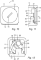
- a part of the device 10 is illustrated, wherein an exterior side of the locking device 13 is illustrated more in detail according to one embodiment.
- the locking device 13 is arranged in a wall part of the first element 11, wherein an exterior face of the locking device 13, for example, extends in a plane of said wall.
- the locking device 13 comprises a groove 16 for receiving a tool, such as a screwdriver, the peripheral part of a coin or any other suitable tool for rotating the locking device 13.
- the groove 16 extends across the exterior face of the locking device 13.
- the locking device 13 comprises an axis of rotation A, a cylinder portion 17, a flange 18 and a protrusion 19.
- the cylinder portion 17 extends along the axis of rotation A and is arranged between the flange 18 and the protrusion 19.
- the flange 18 extends radially from a first end of the cylinder portion 17, wherein the protrusion 19 extends axially from a second end of the cylinder portion 17.
- the flange 18 extends around the entire periphery of the first end of the cylinder portion 17.
- the flange 18 is interrupted by cuts forming tabs or similar distributed around the periphery of the first end of the cylinder portion 17.
- the cylinder portion 17 is formed with a circular cross section or a substantially circular cross section to be able to be rotated in an aperture, which is described more in detail below.
- the protrusion 19 is displaced from the axis of rotation A. Hence, the protrusion 19 is displaced in the radial direction in relation to the axis of rotation A and a centre of the locking device 13.
- the protrusion 19 is, e.g. formed as an axial extension of the periphery of the cylinder portion 17 around a part thereof, wherein the protrusion 19, for example, is formed as an arc-shaped rib.
- the locking device 13 also comprises a first abutment surface 20 being offset from the axis A of rotation.
- the locking device 13 also comprises one or more radial extensions 21, such as a radially extending tabs or similar.
- the radial extension 21 is connected to the second end of the cylinder portion 17, forming a gap in the axial direction between the radial extension 21 and the flange 18. Hence, the radial extension 21 is axially displaced in relation to the flange 18.
- the locking device 13 is provided with an axially extending pin 22, e.g. extending axially from the cylinder portion 17, said pin 22 comprising the first abutment surface 20 and being positioned offset from the axis of rotation A.
- the first abutment surface 20 is formed by a radial extension extending radially from the cylinder portion 17.
- the device 10 comprises the first element 11, the second element 12, the locking device 13 and the optional third element 14.
- the first element 11, the second element 12, the locking device 13 and the third element 14 are, for example, made entirely of plastic materials, such as moulded plastic articles.
- the device 10 comprises metal parts, such as an exterior part of the locking device 13.
- the first element 11 is, for example, formed as a casing having an aperture 23 and a notch 24 for receiving the locking device 13.
- the first element 11 comprises three interconnected walls substantially forming a U-shape, and first and second end walls, wherein the aperture 23 is arranged in one of said end walls.
- the locking device 13 is formed with the groove 16 for receiving a tool to rotate the locking device 13.
- the locking device 13 also comprises the radial extension 21 to be fitted through the notch 24.
- the first element 11 comprises the through aperture 23 and the notch 24, wherein the aperture 23 is formed with an irregularity in the form of the notch 24.
- the aperture 23 is circular or substantially circular, wherein the notch 24 extends from an imaginary circumference of the circular aperture 23 and around a portion of the circumference to form the notch 24 in the first element 11.
- the aperture 23 can also be described as having a circular or substantially circular first part and a second part in the form of the notch 24 as an irregularity on the periphery of the circular part of the aperture 23.
- the notch 24 is substantially rectangular but can be of any desired shape.
- the radial extension 21 of the locking device 13 is aligned with the notch 24, so that the protrusion 19 and the cylinder portion 17 of the locking device 13 can be inserted into the aperture 23.
- the protrusion 19 is inserted into the aperture 23.
- the radial extension 21 is fitted over the notch 24 while the cylinder portion 17 is fitted over the aperture 23.
- the cylinder portion 17 is inserted into the aperture 23 while the radial extension 21 is inserted through the notch 24 until the flange 18 engages a first side, such as an exterior side, of the first element 11, so that the cylinder portion 17 is rotationally fitted in the aperture 23 and the radial extension 21 is arranged at a second side of the first element 11, such as an interior side.
- the aperture 23 is arranged for receiving the cylinder portion 17 of the locking device 13. Then the locking device 13 is rotated around the axis of rotation A, so that the radial extension 21 is rotationally displaced in relation to the notch 24 and the locking device 13 is prevented from axial displacement by means of the flange 19 and the radial extension 21.
- the flange 18 prevents the locking device 13 from falling into the aperture 23.
- the flange 18 has larger diameter than the aperture 24 or comprises parts extending radially beyond the circumference of the aperture 23.
- the protrusion 19 is arranged for locking engagement with the projection 26 by rotation of the locking device 13, wherein displacement of the first element 11 in relation to the second element 12 is prevented.
- the protrusion 19 engages the projection 26.
- the radially extending portion 27 supporting the projection 26 extends axially, so that the projection 26 is positioned between the protrusion 19 and the axis A of rotation.
- the engaging surfaces of the protrusion 19 and the projection 26 are arc-shaped for locking the first element 11 to the second element 12 efficiently.
- the engaging surfaces of the protrusion 19 and the projection 26 are arc-shaped around the axis A.
- the engaging surfaces of the protrusion 19 and the projection 26 are arranged for locking in the radial direction.
- Axial displacement of the first element 11 in relation to the second element 12 is, for example, prevented by means of pins and openings or any other suitable parts of the first and second elements 11, 12.
- the first and second elements 11, 12 comprise radially extending and interacting parts to prevent undesired axial displacement between them.
- the third element 14 according to one embodiment is disclosed in Fig. 8 .
- the third element 14 is, for example, arranged as a back cover or an inner frame for mounting on or in the first element 11.
- the third element 14 is provided with a stop 25 to prevent the locking device 13 from rotating to a position in which the radial extension 21 is aligned with the notch 24.
- the third element 14 prevents the locking device 13 from rotating back beyond the stop 25.
- the stop 25 is, e.g. formed as an axially extending part.
- the stop 25 is positioned to engage a radially extending element of the locking device 13, such as the radial extension 21 to prevent further rotation of the locking device 13.
- the third element 14 is fixed to the first element 11.
- the third element 14 is fixed to the first element 11 by means of conventional fastening means, such as screws, snap-locking means using mutually engaging parts and an inherent flexibility of the material, adhesives or any other suitable fastening means.
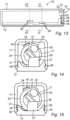
- the second element 12 according to one embodiment is disclosed in Fig. 9 .
- the second element 12 is provided with an axially extending projection 26 for interaction with the protrusion 19 of the locking device 13.
- the projection 26 is supported by a radially extending portion 27 to form a gap between a base of the second element 12 and the projection 26 for receiving the protrusion 19.
- the second element 12 comprises a second abutment surface 28 for interaction with the first abutment surface 20 of the locking device 13.
- the second abutment surface 28 is arranged in the rotational path of the first abutment surface 20, said first abutment surface 20 being displaced from the axis of rotation A.
- the second abutment surface 28 is arranged as a stop for the rotating locking device 13 by engaging the first abutment surface 20 thereof.
- the second abutment surface 28 extends in the axial and/or radial direction.
- the second abutment surface 28 extends substantially in parallel to a plane of the base of the second element 12.
- the second abutment surface 28 is formed by the projection 26.
- the second abutment surface 28 is formed by another axially and/or radially extending component or portion of the second element 12.
- the second element 12 comprises a first set of flexible connecting means 29, such as bulges, for interaction with a corresponding first set of flexible connecting means, such as bulges or indentations, of the first element 11 to detachably connect the first and second elements 11, 12 in a first position by inherent resilient flexible properties of said flexible connecting means and/or the first and second elements 11, 12.
- the second element 12 also comprises a second set of flexible connecting means 30 for interaction with a corresponding second set of flexible connecting means of the first element 11 to detachably connect the first and second elements 11, 12 in a second position, which second position is displaced in relation to the first position, by inherent resilient flexible properties of said flexible connecting means and/or the first and second elements 11, 12.
- the device 10 is illustrated schematically in a locked position, wherein the locking device 13 is connected to the first element 11 and the protrusion 19 is engaging the projection 26 to prevent radial displacement of the first element 11 in relation to the second element 12.
- the first element 11 with the locking device 13 is fitted to the second element 12.
- the projection 26 extends substantially in the same direction as the protrusion 19, such as axially, and is displaced radially in relation to the protrusion 19, so that the protrusion 19 can be positioned in contact with the projection 26 to prevent radial displacement of the first element 11 in relation to the second element 12.
- the protrusion 19 and the projection 26 are formed with mutually engaging surfaces resulting from the axially extending protrusion 19 and projection 26.
- the projection 26 is arranged on the radially extending portion 27, wherein the radially extending portion 27 and the projection 26 together from an L-shaped structure or a hook structure. In the locked position the first element 11 is arranged in a predetermined first position in relation to the second element 12.
- first and second elements 11, 12 are aligned in said first position.
- first and second elements 11, 12 are engaging each other along substantially their entire length in the axial direction, wherein the first and second elements 11, 12 are arranged without a gap between them in said first position.
- the first element 11 is connected to the second element 12 in the first position and the locked position also by means of the first set of flexible connecting means 29, wherein the second set of flexible connecting means 30 are disengaged from each other as illustrated in Fig. 15 .
- the first and second sets of flexible connecting means 29, 30 are formed by interacting bugles and indentations.
- the first abutment surface 20 is arranged with a gap to the second abutment surface 28 in the locked position.
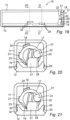
- the device 10 is illustrated schematically in the unlocked position, wherein the locking device 13 is connected to the first element 11 and the protrusion 19 is disengaged from the projection 26 to allow radial displacement of the first element 11 in relation to the second element 12.
- the first and second elements 11, 12 are still in the first position.
- the first element 11 with the locking device 13 is still fitted to the second element 12.
- the first abutment surface 20 is rotated towards the second abutment surface 28.
- the first abutment surface 20 is brought to engage the second abutment surface 28, which is illustrated in Figs. 17-21 .
- the device 10 is in the unlocked position but the first element 11 is still in the first position in relation to the second element 12, wherein the first and second elements 11, 12, e.g. are aligned.
- the first and second elements 11, 12 are, e.g. still engaging each other along substantially their entire length in the axial direction, wherein the first and second elements 11, 12, e.g. are arranged without a gap between them.
- the first element 11 is still connected to the second element 12 also by means of the first set of flexible connecting means 29, wherein the second set of flexible connecting means 30 are disengaged from each other as illustrated in Fig. 21 .
- the device 10 is illustrated schematically, wherein the first element 11 has been displaced in relation to the second element 12, so that the first and second elements 11, 12 are in a second position, which second position is displaced in relation to the first position described above.
- the device 10 is in the unlocked position and the locking device 13 has been rotated further from the unlocked position, which is illustrated by means of the arrow C in Fig. 22 .
- the locking device 13 has been rotated further in the same direction as from the locked position to the unlocked position.
- the protrusion 19 has been rotated further away from the projection 26 and the protrusion 19 is disengaged from the projection 26 to allow radial displacement of the first element 11 in relation to the second element 12.
- the first abutment surface 20 is forced against the second abutment surface 28 and results in a displacement of the locking device 13 in relation to the second element 12.
- the locking device 13 is rotatably connected to the first element 11 the first element 11 is brought along the locking device 13 and, hence, also displaced in relation to the second element 12.
- the first element 11 Due to continued rotation of the locking device 13 after the first abutment surface 20 has engaged the second abutment surface 28 the first element 11 will be forced away from the second element 12, substantially in the radial direction, i.e. perpendicular to the axis of rotation A of the locking device 13.
- the displacement of the first element 11 in relation to the second element results in an indication, such as a visual indication, e.g. in the form of a gap between parts of the first and second elements 11, 12, that the device 10 is in the unlocked position and that the first element 11 is releasable from the second element 12.
- the first set of flexible connecting means 29 has been disengaged, wherein the first element 11 is detachably connected to the second element 12 in the displaced second position by means of the second set of flexible connecting means 30. It is understood that the first and/or second sets of flexible connecting means 29, 30 are optional.
- the locking device 13 is arranged with a predetermined frictional resistance against the first element 11 depending on the rotational position of the locking device 13.
- the locking device 13 and the first element 11 are arranged to provide a higher rotational friction of the locking device 13 in a first rotational position area of the locking device 13 than in a second rotational position area thereof.
- the higher rotational friction is set so that a tool is required for rotating the locking device 13, wherein the lower rotational friction is set to allow rotation of the locking device 13 without any tool.
- the first rotational position area corresponds to the locked position, wherein the second rotational position area corresponds to the unlocked position of the locking device 13.
- the higher rotational friction is set to prevent the locking device 13 from being rotated from the locked position to the unlocked position without a tool.
- the higher rotational friction prevents the locking device 13 from unintentional rotation from unlocked position to locked position, e.g. during transport or handling of the device 10 being delivered in unlocked position.
- the lower rotational friction which for example is zero, is set so that the locking device 13 easily can be rotated during assembly of the device 10.
- the first rotational position area is an area extending from a first angle to a second angle, wherein the first angle is 0° and corresponds to the end position of the locking device 13 in the locked position.
- the second rotational position area extends from the second angle to a third angle.
- the second angle is larger than the first angle and hence larger than 0° but smaller than the third angle and also less than 360°.
- the second angle is 270° or less or 180° or less.
- the second angle is, e.g. 20-180 degrees, 45-90 degrees or 50-55 degrees, such as 52 degrees.
- the third angle is larger than the second angle and less than 360°.
- the third angle is 270° or less or 180° or less.
- the third angle is 30-300 degrees, 45-180 degrees or 50-135 degrees, such as 90 degrees.
- At least the higher rotational friction of the locking device 13 is provided by means of one or more axial elevations (not illustrated in the drawings) on the first element 11 for engaging the flange 18 and/or the radial extension 21 of the locking device 13 when the locking device 13 is in its first rotational position area.
- the dimension of said one or more elevations in the axial direction is set to provide the desired rotational friction.
- the size of the first rotational position area is, e.g. set by the length of the flange surface and/or radial extension surface engaging said one or more elevations.
Landscapes
- Physics & Mathematics (AREA)
- General Physics & Mathematics (AREA)
- Engineering & Computer Science (AREA)
- Mechanical Engineering (AREA)
- Snaps, Bayonet Connections, Set Pins, And Snap Rings (AREA)
- Control Of Vending Devices And Auxiliary Devices For Vending Devices (AREA)
- Burglar Alarm Systems (AREA)
- Pivots And Pivotal Connections (AREA)
- Mutual Connection Of Rods And Tubes (AREA)
- Handcart (AREA)
- Shovels (AREA)
- Casings For Electric Apparatus (AREA)
Claims (13)
- Einbruchmeldekomponente (10), umfassend ein erstes Element (11), ein zweites Element (12) und eine Verriegelungsvorrichtung (13) zum Verriegeln des ersten Elements (11) mit dem zweiten Element (12), wobei:die Verriegelungsvorrichtung (13) eine Achse (A) einer Drehung und einen Vorsprung (19) für eine Verriegelungswechselwirkung mit einem Vorsprung (26) des zweiten Elements (12) umfasst, und wobei die Verriegelungsvorrichtung (13) mit dem ersten Element (11) verbunden ist und um die Achse (A) der Drehung herum zwischen einer entriegelten Position und einer verriegelten Position drehbar ist, in der der Vorsprung (19) der Verriegelungsvorrichtung den Vorsprung (26) des zweiten Elements (12) in Eingriff nimmt,dadurch gekennzeichnet, dassdie Komponente zum Anzeigen konfiguriert ist, wann das erste Element (11) von dem zweiten Element (12) lösbar ist, die Verriegelungsvorrichtung (13) eine erste Anlageoberfläche (20) umfasst, die von der Achse (A) der Drehung versetzt ist, wobei die erste Anlageoberfläche (20) durch einen axial vorspringenden Stift (22) der Verriegelungsvorrichtung (13) ausgebildet ist, und dadurch, dass das zweite Element (12) eine zweite Anlageoberfläche (28) umfasst, die in einer Position zum Ineingriffnehmen der ersten Anlageoberfläche (20) der Verriegelungsvorrichtung (13) angeordnet ist, wenn die Verriegelungsvorrichtung (13) in die entriegelte Position gedreht wurde, wobei in der entriegelten Position der Vorsprung (19) der Verriegelungsvorrichtung (13) von dem Vorsprung (26) des zweiten Elements (12) außer Eingriff gebracht wird, und, durch weitere Drehung der Verriegelungsvorrichtung (13), die erste Anlageoberfläche (20) gegen die zweite Anlageoberfläche (28) gedrückt wird, um die Verriegelungsvorrichtung (13) in Bezug auf das zweite Element (12) zu verschieben, während das erste Element entlang (11) damit bewegt wird, um das erste und das zweite Element (11, 12) in Bezug auf einander in einer Richtung im Allgemeinen orthogonal zu der Achse (A) der Drehung zu verschieben.
- Einbruchmeldekomponente nach Anspruch 1, wobei die erste Anlageoberfläche (20) gewölbt ist.
- Einbruchmeldekomponente nach Anspruch 1 oder 2, wobei sich der Vorsprung (26) des zweiten Elements (12) axial erstreckt und zwischen dem Vorsprung (19) und der Achse (A) angeordnet ist, wenn die Verriegelungsvorrichtung (13) in ihrer verriegelten Position ist, wobei der Vorsprung (26) eine radial nach außen gerichtete Verriegelungsoberfläche zum Ineingriffnehmen des Vorsprungs (19) der Verriegelungsvorrichtung (13) in der verriegelten Position und eine radial nach innen gerichtete Fläche aufweist, die die zweite Anlageoberfläche (28) ausbildet.
- Einbruchmeldekomponente nach einem der vorstehenden Ansprüche, wobei der Vorsprung (19) von der Achse (A) der Drehung versetzt ist und wobei die erste Anlageoberfläche (20) um die Achse (A) herum in Bezug auf den Vorsprung (19) winkelig verschoben ist.
- Einbruchmeldekomponente nach einem der vorstehenden Ansprüche, wobei das erste und das zweite Element (11, 12) flexible Verbindungsmittel (30) zum lösbaren Verbinden des ersten Elements (11) mit dem zweiten Element (12) durch inhärente flexible Eigenschaften davon umfassen, und wobei die flexiblen Verbindungsmittel (30) positioniert sind, um das erste und das zweite Element lösbar zu verbinden, wenn das erste Element (11) in Bezug auf das zweite Element (12) verschoben wird.
- Einbruchmeldekomponente nach Anspruch 5, wobei das erste beziehungsweise das zweite Element (11, 12) einen ersten Satz flexibler Verbindungsmittel (29) und einen zweiten Satz flexibler Verbindungsmittel (30) umfasst, wobei der erste Satz (29) positioniert ist, um das erste und das zweite Element (11, 12) in einer ersten Position lösbar zu verbinden, und wobei der zweite Satz (30) in Bezug auf den ersten Satz (29) radial verschoben ist, um das erste und das zweite Element in eine zweite Position lösbar zu verbinden.
- Einbruchmeldekomponente (10) nach einem der vorstehenden Ansprüche, wobei die Verriegelungsvorrichtung (13) einen Zylinderabschnitt (17), der sich entlang der Achse (A) der Drehung erstreckt, und einen Flansch (18) umfasst, der sich von einem ersten Ende des Zylinderabschnitts (17) radial erstreckt, wobei der Vorsprung (19) von einem zweiten Ende des Zylinderabschnitts (17) vorspringt, wobei das erste Element (11) mit einer Durchgangsöffnung (23) zum Aufnehmen des Zylinderabschnitts (17) der Verriegelungsvorrichtung (13) versehen ist, und wobei der Flansch (18) der Verriegelungsvorrichtung (13) eine erste Seite des ersten Elements (11) an der Öffnung (23) in Eingriff nimmt.
- Einbruchmeldekomponente (10) nach Anspruch 7, wobei ein drittes Element (14) an dem ersten Element (11) befestigt ist, wobei die Verriegelungsvorrichtung (13) eine radiale Erstreckung (21) umfasst, die sich um einen Teil des Umfangs des Zylinderabschnitts (17) herum erstreckt, wobei die Öffnung (23) mit einer Kerbe (24) zum Aufnehmen der radialen Erstreckung (21) ausgebildet ist und wobei das dritte Element (14) mit einem Anschlag (25) versehen ist, um die Verriegelungsvorrichtung (13) an dem Drehen in eine Position zu hindern, in der die Erstreckung (21) an der Kerbe (24) ausgerichtet ist.
- Einbruchmeldekomponente nach einem der vorstehenden Ansprüche, wobei das erste Element (11) eine Gehäusefrontabdeckung ist.
- Einbruchmeldekomponente nach einem der vorstehenden Ansprüche, wobei das zweite Element (12) eine Halterung oder eine Rückabdeckung ist.
- Einbruchmeldekomponente nach einem der vorstehenden Ansprüche, umfassend einen Detektor und/oder einen Prozessor und/oder drahtlose Kommunikationsmittel.
- Verfahren zum Anzeigen, wann ein erstes Element (11) von einem zweiten Element (12) einer Vorrichtung (10) in Form einer Einbruchmeldekomponente lösbar ist, umfassend das erste Element (11), das zweite Element (12) und eine Verriegelungsvorrichtung (13) zum Befestigen des ersten Elements (11) an dem zweiten Element (12), das Verfahren umfassend die Schrittea) Drehen der Verriegelungsvorrichtung (13) um eine Achse (A) der Drehung herum in eine entriegelte Position, wobei in der entriegelten Position ein Vorsprung (19) der Verriegelungsvorrichtung (13) von einem Vorsprung (26) des zweiten Elements (12) außer Eingriff gebracht ist,b) Bringen einer ersten Anlageoberfläche (20) der Verriegelungsvorrichtung (13) dazu, um durch die Drehung eine zweite Anlageoberfläche (28) des zweiten Elements (12) in Eingriff zu nehmen, wobei die erste Anlageoberfläche (20) durch einen axial vorspringenden Stift (22) der Verriegelungsvorrichtung (13) ausgebildet ist, undc) durch weitere Drehung der Verriegelungsvorrichtung (13) um die Achse (A) der Drehung herum, die erste Anlageoberfläche (20) gegen die zweite Anlageoberfläche (28) drückt, die die Verriegelungsvorrichtung (13) und das erste Element (11) in Bezug auf das zweite Element (12) in einer Richtung verschiebt, die im Allgemeinen orthogonal zu der Achse (A) der Drehung der Verriegelungsvorrichtung ist, um anzuzeigen, dass das erste Element (11) von dem zweiten Element (12) lösbar ist.
- Verfahren nach Anspruch 12, umfassend die Schritte des lösbaren Verbindens des ersten Elements (11) mit dem zweiten Element (12) in einer ersten Position, die der verriegelten Position entspricht, mittels eines ersten Satzes flexibler Verbindungsmittel (29) des ersten und des zweiten Elements (11, 12) durch inhärente flexible Eigenschaften davon, und nach Schritt c), des lösbaren Verbindens des ersten Elements (11) mit dem zweiten Element (12) in einer verschobenen zweiten Position mittels eines zweiten Satzes flexibler Verbindungsmittel (30) des ersten und des zweiten Elements (11, 12) durch inhärente flexible Eigenschaften davon.
Priority Applications (3)
| Application Number | Priority Date | Filing Date | Title |
|---|---|---|---|
| EP22151730.3A EP4006855B1 (de) | 2016-11-23 | 2016-11-23 | Komponente einer einbruchmeldeanlage und verfahren zur anzeige des gelösten zustandes eines ersten elements von einem zweiten element |
| PL22151730.3T PL4006855T3 (pl) | 2016-11-23 | 2016-11-23 | Komponent alarmu informującego o włamaniu oraz sposób wskazywania, kiedy pierwszy element jest możliwy do odłączenia od drugiego elementu |
| ES22151730T ES2977113T3 (es) | 2016-11-23 | 2016-11-23 | Un componente de alarma de intrusión y método para indicar cuándo un primer elemento es liberable de un segundo elemento |
Applications Claiming Priority (2)
| Application Number | Priority Date | Filing Date | Title |
|---|---|---|---|
| EP22151730.3A EP4006855B1 (de) | 2016-11-23 | 2016-11-23 | Komponente einer einbruchmeldeanlage und verfahren zur anzeige des gelösten zustandes eines ersten elements von einem zweiten element |
| EP16200221.6A EP3327687B1 (de) | 2016-11-23 | 2016-11-23 | Vorrichtung und verfahren zur anzeige des gelösten zustandes eines ersten elements von einem zweiten element |
Related Parent Applications (1)
| Application Number | Title | Priority Date | Filing Date |
|---|---|---|---|
| EP16200221.6A Division EP3327687B1 (de) | 2016-11-23 | 2016-11-23 | Vorrichtung und verfahren zur anzeige des gelösten zustandes eines ersten elements von einem zweiten element |
Publications (3)
| Publication Number | Publication Date |
|---|---|
| EP4006855A1 EP4006855A1 (de) | 2022-06-01 |
| EP4006855B1 true EP4006855B1 (de) | 2024-03-13 |
| EP4006855C0 EP4006855C0 (de) | 2024-03-13 |
Family
ID=57569865
Family Applications (2)
| Application Number | Title | Priority Date | Filing Date |
|---|---|---|---|
| EP16200221.6A Active EP3327687B1 (de) | 2016-11-23 | 2016-11-23 | Vorrichtung und verfahren zur anzeige des gelösten zustandes eines ersten elements von einem zweiten element |
| EP22151730.3A Active EP4006855B1 (de) | 2016-11-23 | 2016-11-23 | Komponente einer einbruchmeldeanlage und verfahren zur anzeige des gelösten zustandes eines ersten elements von einem zweiten element |
Family Applications Before (1)
| Application Number | Title | Priority Date | Filing Date |
|---|---|---|---|
| EP16200221.6A Active EP3327687B1 (de) | 2016-11-23 | 2016-11-23 | Vorrichtung und verfahren zur anzeige des gelösten zustandes eines ersten elements von einem zweiten element |
Country Status (9)
| Country | Link |
|---|---|
| EP (2) | EP3327687B1 (de) |
| AU (1) | AU2017365069B2 (de) |
| CL (1) | CL2019001387A1 (de) |
| ES (2) | ES2909772T3 (de) |
| IL (1) | IL266797B (de) |
| PE (1) | PE20191279A1 (de) |
| PL (1) | PL4006855T3 (de) |
| PT (1) | PT3327687T (de) |
| WO (1) | WO2018095745A1 (de) |
Family Cites Families (6)
| Publication number | Priority date | Publication date | Assignee | Title |
|---|---|---|---|---|
| GB406811A (en) * | 1932-11-08 | 1934-03-08 | William Henry Tonks | Improvements relating to fastenings for windows, doors and the like |
| DE7422116U (de) * | 1974-06-28 | 1974-11-21 | Esser K Kg | Schacht- und Kanalabdeckung |
| AT336716B (de) * | 1975-06-26 | 1977-05-25 | Siemens Ag Oesterreich | Verriegelungsvorrichtung fur gehause mit verschwenkbarem oder einsetzbarem deckel |
| TWI367064B (en) * | 2007-09-19 | 2012-06-21 | Asustek Comp Inc | Fixing base |
| DE102009010802B3 (de) * | 2009-02-27 | 2010-04-22 | Lic Langmatz Gmbh | Schacht mit einem Deckel |
| ES2746153T3 (es) | 2014-10-15 | 2020-03-04 | Verisure Sarl | Dispositivo que comprende un primer elemento, un segundo elemento y un dispositivo de bloqueo para fijar el primer elemento al segundo elemento y método para ensamblar dicho dispositivo |
-
2016
- 2016-11-23 EP EP16200221.6A patent/EP3327687B1/de active Active
- 2016-11-23 PL PL22151730.3T patent/PL4006855T3/pl unknown
- 2016-11-23 ES ES16200221T patent/ES2909772T3/es active Active
- 2016-11-23 PT PT162002216T patent/PT3327687T/pt unknown
- 2016-11-23 EP EP22151730.3A patent/EP4006855B1/de active Active
- 2016-11-23 ES ES22151730T patent/ES2977113T3/es active Active
-
2017
- 2017-11-10 AU AU2017365069A patent/AU2017365069B2/en active Active
- 2017-11-10 WO PCT/EP2017/078890 patent/WO2018095745A1/en not_active Ceased
- 2017-11-10 IL IL266797A patent/IL266797B/en unknown
- 2017-11-10 PE PE2019001063A patent/PE20191279A1/es unknown
-
2019
- 2019-05-23 CL CL2019001387A patent/CL2019001387A1/es unknown
Also Published As
| Publication number | Publication date |
|---|---|
| AU2017365069A1 (en) | 2019-06-13 |
| WO2018095745A1 (en) | 2018-05-31 |
| PE20191279A1 (es) | 2019-09-20 |
| CL2019001387A1 (es) | 2019-10-18 |
| IL266797B (en) | 2022-09-01 |
| PL4006855T3 (pl) | 2024-07-22 |
| EP3327687A1 (de) | 2018-05-30 |
| EP3327687B1 (de) | 2022-01-19 |
| EP4006855A1 (de) | 2022-06-01 |
| AU2017365069B2 (en) | 2021-12-23 |
| IL266797A (en) | 2019-08-29 |
| BR112019010535A2 (pt) | 2019-09-17 |
| PT3327687T (pt) | 2022-04-04 |
| ES2909772T3 (es) | 2022-05-10 |
| ES2977113T3 (es) | 2024-08-19 |
| EP4006855C0 (de) | 2024-03-13 |
Similar Documents
| Publication | Publication Date | Title |
|---|---|---|
| JP7005586B2 (ja) | 接続装置における又は接続装置に関する改良 | |
| US10746347B2 (en) | Display device | |
| US5287664A (en) | Metal stud interlocking conduit strap | |
| JP2019521302A5 (de) | ||
| US20190376626A1 (en) | Apparatus and method for securing elongate objects | |
| CA2989901C (en) | Connecting apparatus and bolt assembly | |
| US20150197923A1 (en) | Plumbing outlet box with integrated mounting features | |
| CN101936330B (zh) | 铰链结构 | |
| US9774815B2 (en) | Locking mount for set top box | |
| EP4006855B1 (de) | Komponente einer einbruchmeldeanlage und verfahren zur anzeige des gelösten zustandes eines ersten elements von einem zweiten element | |
| EP3209889B1 (de) | Verbesserungen an oder im zusammenhang mit verbindungsvorrichtungen | |
| SE0900203A1 (sv) | Ventilationsanordning | |
| US11530713B2 (en) | Self-locking mounting system | |
| JP2013024405A (ja) | 吊ボルト連結具 | |
| EP3009810B1 (de) | Vorrichtung mit einem ersten Element, einem zweiten Element und einer Verriegelungsvorrichtung zur Befestigung des ersten Elements an das zweite Element und Verfahren zur Montage solch einer Vorrichtung | |
| JP2005086393A (ja) | 取付装置 | |
| BR112019010535B1 (pt) | Um dispositivo e um método para indicar quando um primeiro elemento é liberável de um segundo elemento | |
| JP5392557B2 (ja) | 物品の取り付け具 | |
| CN116264379A (zh) | 连接件 | |
| JP6410610B2 (ja) | 埋設式ガス栓の取付構造 | |
| CN115727014A (zh) | 送风装置和电气产品 | |
| EP2930279A1 (de) | Kupplungsvorrichtung zum verbinden zweier stangen eines rahmens | |
| CN101155488A (zh) | 夹持装置 | |
| JP2016048095A (ja) | 制震装置 |
Legal Events
| Date | Code | Title | Description |
|---|---|---|---|
| PUAI | Public reference made under article 153(3) epc to a published international application that has entered the european phase |
Free format text: ORIGINAL CODE: 0009012 |
|
| STAA | Information on the status of an ep patent application or granted ep patent |
Free format text: STATUS: THE APPLICATION HAS BEEN PUBLISHED |
|
| AC | Divisional application: reference to earlier application |
Ref document number: 3327687 Country of ref document: EP Kind code of ref document: P |
|
| AK | Designated contracting states |
Kind code of ref document: A1 Designated state(s): AL AT BE BG CH CY CZ DE DK EE ES FI FR GB GR HR HU IE IS IT LI LT LU LV MC MK MT NL NO PL PT RO RS SE SI SK SM TR |
|
| STAA | Information on the status of an ep patent application or granted ep patent |
Free format text: STATUS: REQUEST FOR EXAMINATION WAS MADE |
|
| 17P | Request for examination filed |
Effective date: 20221123 |
|
| RBV | Designated contracting states (corrected) |
Designated state(s): AL AT BE BG CH CY CZ DE DK EE ES FI FR GB GR HR HU IE IS IT LI LT LU LV MC MK MT NL NO PL PT RO RS SE SI SK SM TR |
|
| GRAP | Despatch of communication of intention to grant a patent |
Free format text: ORIGINAL CODE: EPIDOSNIGR1 |
|
| STAA | Information on the status of an ep patent application or granted ep patent |
Free format text: STATUS: GRANT OF PATENT IS INTENDED |
|
| RIC1 | Information provided on ipc code assigned before grant |
Ipc: E05B 35/00 20060101ALN20230925BHEP Ipc: E05B 15/16 20060101ALN20230925BHEP Ipc: E05B 17/00 20060101ALI20230925BHEP Ipc: E05C 3/04 20060101ALI20230925BHEP Ipc: E05B 41/00 20060101ALI20230925BHEP Ipc: H05K 5/02 20060101ALI20230925BHEP Ipc: G08B 13/08 20060101AFI20230925BHEP |
|
| INTG | Intention to grant announced |
Effective date: 20231013 |
|
| GRAS | Grant fee paid |
Free format text: ORIGINAL CODE: EPIDOSNIGR3 |
|
| GRAA | (expected) grant |
Free format text: ORIGINAL CODE: 0009210 |
|
| STAA | Information on the status of an ep patent application or granted ep patent |
Free format text: STATUS: THE PATENT HAS BEEN GRANTED |
|
| AC | Divisional application: reference to earlier application |
Ref document number: 3327687 Country of ref document: EP Kind code of ref document: P |
|
| AK | Designated contracting states |
Kind code of ref document: B1 Designated state(s): AL AT BE BG CH CY CZ DE DK EE ES FI FR GB GR HR HU IE IS IT LI LT LU LV MC MK MT NL NO PL PT RO RS SE SI SK SM TR |
|
| REG | Reference to a national code |
Ref country code: GB Ref legal event code: FG4D |
|
| REG | Reference to a national code |
Ref country code: CH Ref legal event code: EP |
|
| REG | Reference to a national code |
Ref country code: DE Ref legal event code: R096 Ref document number: 602016086384 Country of ref document: DE |
|
| REG | Reference to a national code |
Ref country code: IE Ref legal event code: FG4D |
|
| U01 | Request for unitary effect filed |
Effective date: 20240409 |
|
| U07 | Unitary effect registered |
Designated state(s): AT BE BG DE DK EE FI FR IT LT LU LV MT NL PT SE SI Effective date: 20240416 |
|
| PG25 | Lapsed in a contracting state [announced via postgrant information from national office to epo] |
Ref country code: GR Free format text: LAPSE BECAUSE OF FAILURE TO SUBMIT A TRANSLATION OF THE DESCRIPTION OR TO PAY THE FEE WITHIN THE PRESCRIBED TIME-LIMIT Effective date: 20240614 |
|
| PG25 | Lapsed in a contracting state [announced via postgrant information from national office to epo] |
Ref country code: RS Free format text: LAPSE BECAUSE OF FAILURE TO SUBMIT A TRANSLATION OF THE DESCRIPTION OR TO PAY THE FEE WITHIN THE PRESCRIBED TIME-LIMIT Effective date: 20240613 Ref country code: HR Free format text: LAPSE BECAUSE OF FAILURE TO SUBMIT A TRANSLATION OF THE DESCRIPTION OR TO PAY THE FEE WITHIN THE PRESCRIBED TIME-LIMIT Effective date: 20240313 |
|
| PG25 | Lapsed in a contracting state [announced via postgrant information from national office to epo] |
Ref country code: RS Free format text: LAPSE BECAUSE OF FAILURE TO SUBMIT A TRANSLATION OF THE DESCRIPTION OR TO PAY THE FEE WITHIN THE PRESCRIBED TIME-LIMIT Effective date: 20240613 Ref country code: HR Free format text: LAPSE BECAUSE OF FAILURE TO SUBMIT A TRANSLATION OF THE DESCRIPTION OR TO PAY THE FEE WITHIN THE PRESCRIBED TIME-LIMIT Effective date: 20240313 Ref country code: GR Free format text: LAPSE BECAUSE OF FAILURE TO SUBMIT A TRANSLATION OF THE DESCRIPTION OR TO PAY THE FEE WITHIN THE PRESCRIBED TIME-LIMIT Effective date: 20240614 |
|
| REG | Reference to a national code |
Ref country code: ES Ref legal event code: FG2A Ref document number: 2977113 Country of ref document: ES Kind code of ref document: T3 Effective date: 20240819 |
|
| PG25 | Lapsed in a contracting state [announced via postgrant information from national office to epo] |
Ref country code: IS Free format text: LAPSE BECAUSE OF FAILURE TO SUBMIT A TRANSLATION OF THE DESCRIPTION OR TO PAY THE FEE WITHIN THE PRESCRIBED TIME-LIMIT Effective date: 20240713 |
|
| PG25 | Lapsed in a contracting state [announced via postgrant information from national office to epo] |
Ref country code: SM Free format text: LAPSE BECAUSE OF FAILURE TO SUBMIT A TRANSLATION OF THE DESCRIPTION OR TO PAY THE FEE WITHIN THE PRESCRIBED TIME-LIMIT Effective date: 20240313 |
|
| PG25 | Lapsed in a contracting state [announced via postgrant information from national office to epo] |
Ref country code: CZ Free format text: LAPSE BECAUSE OF FAILURE TO SUBMIT A TRANSLATION OF THE DESCRIPTION OR TO PAY THE FEE WITHIN THE PRESCRIBED TIME-LIMIT Effective date: 20240313 |
|
| PG25 | Lapsed in a contracting state [announced via postgrant information from national office to epo] |
Ref country code: SK Free format text: LAPSE BECAUSE OF FAILURE TO SUBMIT A TRANSLATION OF THE DESCRIPTION OR TO PAY THE FEE WITHIN THE PRESCRIBED TIME-LIMIT Effective date: 20240313 |
|
| PG25 | Lapsed in a contracting state [announced via postgrant information from national office to epo] |
Ref country code: SM Free format text: LAPSE BECAUSE OF FAILURE TO SUBMIT A TRANSLATION OF THE DESCRIPTION OR TO PAY THE FEE WITHIN THE PRESCRIBED TIME-LIMIT Effective date: 20240313 Ref country code: SK Free format text: LAPSE BECAUSE OF FAILURE TO SUBMIT A TRANSLATION OF THE DESCRIPTION OR TO PAY THE FEE WITHIN THE PRESCRIBED TIME-LIMIT Effective date: 20240313 Ref country code: RO Free format text: LAPSE BECAUSE OF FAILURE TO SUBMIT A TRANSLATION OF THE DESCRIPTION OR TO PAY THE FEE WITHIN THE PRESCRIBED TIME-LIMIT Effective date: 20240313 Ref country code: IS Free format text: LAPSE BECAUSE OF FAILURE TO SUBMIT A TRANSLATION OF THE DESCRIPTION OR TO PAY THE FEE WITHIN THE PRESCRIBED TIME-LIMIT Effective date: 20240713 Ref country code: CZ Free format text: LAPSE BECAUSE OF FAILURE TO SUBMIT A TRANSLATION OF THE DESCRIPTION OR TO PAY THE FEE WITHIN THE PRESCRIBED TIME-LIMIT Effective date: 20240313 |
|
| REG | Reference to a national code |
Ref country code: DE Ref legal event code: R097 Ref document number: 602016086384 Country of ref document: DE |
|
| U20 | Renewal fee for the european patent with unitary effect paid |
Year of fee payment: 9 Effective date: 20241127 |
|
| PLBE | No opposition filed within time limit |
Free format text: ORIGINAL CODE: 0009261 |
|
| STAA | Information on the status of an ep patent application or granted ep patent |
Free format text: STATUS: NO OPPOSITION FILED WITHIN TIME LIMIT |
|
| 26N | No opposition filed |
Effective date: 20241216 |
|
| PG25 | Lapsed in a contracting state [announced via postgrant information from national office to epo] |
Ref country code: MC Free format text: LAPSE BECAUSE OF FAILURE TO SUBMIT A TRANSLATION OF THE DESCRIPTION OR TO PAY THE FEE WITHIN THE PRESCRIBED TIME-LIMIT Effective date: 20240313 |
|
| REG | Reference to a national code |
Ref country code: CH Ref legal event code: U11 Free format text: ST27 STATUS EVENT CODE: U-0-0-U10-U11 (AS PROVIDED BY THE NATIONAL OFFICE) Effective date: 20251201 |
|
| U20 | Renewal fee for the european patent with unitary effect paid |
Year of fee payment: 10 Effective date: 20251126 |
|
| PGFP | Annual fee paid to national office [announced via postgrant information from national office to epo] |
Ref country code: GB Payment date: 20251127 Year of fee payment: 10 |
|
| PGFP | Annual fee paid to national office [announced via postgrant information from national office to epo] |
Ref country code: NO Payment date: 20251128 Year of fee payment: 10 |
|
| PGFP | Annual fee paid to national office [announced via postgrant information from national office to epo] |
Ref country code: CH Payment date: 20251201 Year of fee payment: 10 |
|
| PGFP | Annual fee paid to national office [announced via postgrant information from national office to epo] |
Ref country code: IE Payment date: 20251127 Year of fee payment: 10 |
|
| PGFP | Annual fee paid to national office [announced via postgrant information from national office to epo] |
Ref country code: PL Payment date: 20251103 Year of fee payment: 10 |
|
| PGFP | Annual fee paid to national office [announced via postgrant information from national office to epo] |
Ref country code: ES Payment date: 20251201 Year of fee payment: 10 |
|
| PG25 | Lapsed in a contracting state [announced via postgrant information from national office to epo] |
Ref country code: HU Free format text: LAPSE BECAUSE OF FAILURE TO SUBMIT A TRANSLATION OF THE DESCRIPTION OR TO PAY THE FEE WITHIN THE PRESCRIBED TIME-LIMIT; INVALID AB INITIO Effective date: 20161123 |
|
| PG25 | Lapsed in a contracting state [announced via postgrant information from national office to epo] |
Ref country code: CY Free format text: LAPSE BECAUSE OF FAILURE TO SUBMIT A TRANSLATION OF THE DESCRIPTION OR TO PAY THE FEE WITHIN THE PRESCRIBED TIME-LIMIT; INVALID AB INITIO Effective date: 20161123 |