EP4006887A1 - Appareil d'affichage double face - Google Patents
Appareil d'affichage double face Download PDFInfo
- Publication number
- EP4006887A1 EP4006887A1 EP20942143.7A EP20942143A EP4006887A1 EP 4006887 A1 EP4006887 A1 EP 4006887A1 EP 20942143 A EP20942143 A EP 20942143A EP 4006887 A1 EP4006887 A1 EP 4006887A1
- Authority
- EP
- European Patent Office
- Prior art keywords
- flexible screen
- housing
- double
- display device
- rack
- Prior art date
- Legal status (The legal status is an assumption and is not a legal conclusion. Google has not performed a legal analysis and makes no representation as to the accuracy of the status listed.)
- Granted
Links
Images




Classifications
-
- G—PHYSICS
- G09—EDUCATION; CRYPTOGRAPHY; DISPLAY; ADVERTISING; SEALS
- G09F—DISPLAYING; ADVERTISING; SIGNS; LABELS OR NAME-PLATES; SEALS
- G09F9/00—Indicating arrangements for variable information in which the information is built-up on a support by selection or combination of individual elements
- G09F9/30—Indicating arrangements for variable information in which the information is built-up on a support by selection or combination of individual elements in which the desired character or characters are formed by combining individual elements
- G09F9/301—Indicating arrangements for variable information in which the information is built-up on a support by selection or combination of individual elements in which the desired character or characters are formed by combining individual elements flexible foldable or roll-able electronic displays, e.g. thin LCD, OLED
-
- G—PHYSICS
- G06—COMPUTING OR CALCULATING; COUNTING
- G06F—ELECTRIC DIGITAL DATA PROCESSING
- G06F1/00—Details not covered by groups G06F3/00 - G06F13/00 and G06F21/00
- G06F1/16—Constructional details or arrangements
- G06F1/1613—Constructional details or arrangements for portable computers
- G06F1/1615—Constructional details or arrangements for portable computers with several enclosures having relative motions, each enclosure supporting at least one I/O or computing function
- G06F1/1624—Constructional details or arrangements for portable computers with several enclosures having relative motions, each enclosure supporting at least one I/O or computing function with sliding enclosures, e.g. sliding keyboard or display
-
- G—PHYSICS
- G06—COMPUTING OR CALCULATING; COUNTING
- G06F—ELECTRIC DIGITAL DATA PROCESSING
- G06F1/00—Details not covered by groups G06F3/00 - G06F13/00 and G06F21/00
- G06F1/16—Constructional details or arrangements
- G06F1/1613—Constructional details or arrangements for portable computers
- G06F1/1633—Constructional details or arrangements of portable computers not specific to the type of enclosures covered by groups G06F1/1615 - G06F1/1626
- G06F1/1637—Details related to the display arrangement, including those related to the mounting of the display in the housing
- G06F1/1647—Details related to the display arrangement, including those related to the mounting of the display in the housing including at least an additional display
-
- G—PHYSICS
- G06—COMPUTING OR CALCULATING; COUNTING
- G06F—ELECTRIC DIGITAL DATA PROCESSING
- G06F1/00—Details not covered by groups G06F3/00 - G06F13/00 and G06F21/00
- G06F1/16—Constructional details or arrangements
- G06F1/1613—Constructional details or arrangements for portable computers
- G06F1/1633—Constructional details or arrangements of portable computers not specific to the type of enclosures covered by groups G06F1/1615 - G06F1/1626
- G06F1/1637—Details related to the display arrangement, including those related to the mounting of the display in the housing
- G06F1/1652—Details related to the display arrangement, including those related to the mounting of the display in the housing the display being flexible, e.g. mimicking a sheet of paper, or rollable
-
- G—PHYSICS
- G06—COMPUTING OR CALCULATING; COUNTING
- G06F—ELECTRIC DIGITAL DATA PROCESSING
- G06F1/00—Details not covered by groups G06F3/00 - G06F13/00 and G06F21/00
- G06F1/16—Constructional details or arrangements
- G06F1/1613—Constructional details or arrangements for portable computers
- G06F1/1633—Constructional details or arrangements of portable computers not specific to the type of enclosures covered by groups G06F1/1615 - G06F1/1626
- G06F1/1656—Details related to functional adaptations of the enclosure, e.g. to provide protection against EMI, shock, water, or to host detachable peripherals like a mouse or removable expansions units like PCMCIA cards, or to provide access to internal components for maintenance or to removable storage supports like CDs or DVDs, or to mechanically mount accessories
-
- G—PHYSICS
- G06—COMPUTING OR CALCULATING; COUNTING
- G06F—ELECTRIC DIGITAL DATA PROCESSING
- G06F1/00—Details not covered by groups G06F3/00 - G06F13/00 and G06F21/00
- G06F1/16—Constructional details or arrangements
- G06F1/1613—Constructional details or arrangements for portable computers
- G06F1/1633—Constructional details or arrangements of portable computers not specific to the type of enclosures covered by groups G06F1/1615 - G06F1/1626
- G06F1/1656—Details related to functional adaptations of the enclosure, e.g. to provide protection against EMI, shock, water, or to host detachable peripherals like a mouse or removable expansions units like PCMCIA cards, or to provide access to internal components for maintenance or to removable storage supports like CDs or DVDs, or to mechanically mount accessories
- G06F1/1658—Details related to functional adaptations of the enclosure, e.g. to provide protection against EMI, shock, water, or to host detachable peripherals like a mouse or removable expansions units like PCMCIA cards, or to provide access to internal components for maintenance or to removable storage supports like CDs or DVDs, or to mechanically mount accessories related to the mounting of internal components, e.g. disc drive or any other functional module
-
- G—PHYSICS
- G06—COMPUTING OR CALCULATING; COUNTING
- G06F—ELECTRIC DIGITAL DATA PROCESSING
- G06F1/00—Details not covered by groups G06F3/00 - G06F13/00 and G06F21/00
- G06F1/16—Constructional details or arrangements
- G06F1/1613—Constructional details or arrangements for portable computers
- G06F1/1633—Constructional details or arrangements of portable computers not specific to the type of enclosures covered by groups G06F1/1615 - G06F1/1626
- G06F1/1675—Miscellaneous details related to the relative movement between the different enclosures or enclosure parts
- G06F1/1681—Details related solely to hinges
-
- H—ELECTRICITY
- H04—ELECTRIC COMMUNICATION TECHNIQUE
- H04M—TELEPHONIC COMMUNICATION
- H04M1/00—Substation equipment, e.g. for use by subscribers
- H04M1/02—Constructional features of telephone sets
- H04M1/0202—Portable telephone sets, e.g. cordless phones, mobile phones or bar type handsets
- H04M1/0206—Portable telephones comprising a plurality of mechanically joined movable body parts, e.g. hinged housings
- H04M1/0208—Portable telephones comprising a plurality of mechanically joined movable body parts, e.g. hinged housings characterized by the relative motions of the body parts
- H04M1/0235—Slidable or telescopic telephones, i.e. with a relative translation movement of the body parts; Telephones using a combination of translation and other relative motions of the body parts
- H04M1/0237—Sliding mechanism with one degree of freedom
-
- H—ELECTRICITY
- H04—ELECTRIC COMMUNICATION TECHNIQUE
- H04M—TELEPHONIC COMMUNICATION
- H04M1/00—Substation equipment, e.g. for use by subscribers
- H04M1/02—Constructional features of telephone sets
- H04M1/0202—Portable telephone sets, e.g. cordless phones, mobile phones or bar type handsets
- H04M1/026—Details of the structure or mounting of specific components
- H04M1/0266—Details of the structure or mounting of specific components for a display module assembly
- H04M1/0268—Details of the structure or mounting of specific components for a display module assembly including a flexible display panel
Definitions
- the present disclosure relates to the technical field of display, and more particularly, to a double-sided display device.
- Smart terminals have been widely used in daily life, and users can get more information through the smart terminals. Moreover, in order to increase screen areas of the smart terminals, flexible screens with better flexibility are used in more smart terminals.
- a housing of the smart terminal is divided into a first housing and a second housing.
- the first housing and the second housing can be folded and extended by a bending structure arranged therebetween, and a flexible screen covers an upper surface of the first housing and an upper surface of the second housing.
- a screen with a larger area is needed, the first housing or the second housing is bent, so that the upper surface of the first housing and the upper surface of the second housing are in the same horizontal plane and in an extended state. In this case, the whole flexible screen can be used to display images.
- the first housing or the second housing is bent, so that the first housing is located below the second housing and in a folded state.
- a part of the flexible screen located on the upper surface of the second housing in the entire flexible screen can display images.
- the related art only covers two cases of the screen area of the smart terminal, one is the area of the whole flexible screen, and the other is the area of a half flexible screen, which leads to lower flexibility of adjusting the screen area of the smart terminal and smaller application range.
- the present disclosure provides a double-sided display device, which improves the flexibility of adjusting a display area, enlarges an application range of the double-sided display device, and is convenient for users to use.
- a double-sided display device includes:
- a housing drive part is further included, wherein the housing drive part is configured for driving the second housing to slide relative to the first housing.
- the housing drive part includes a housing drive motor and a rack assembly driven to slide by the housing drive motor.
- the rack assembly includes a fixed seat, a first rack, a second rack and a gear meshed with the first rack and the second rack simultaneously, the fixed seat is fixed to the first housing, the first rack and the second rack are both slidably arranged on the fixed seat, and the second rack is connected with the second housing, and the housing drive motor is connected with the first rack and configured for driving the first rack to slide.
- the flexible screen drive part includes first roll shafts and a flexible screen drive motor configured for driving the first roll shafts to rotate, and the other end of the flexible screen is wound on the two first roll shafts.
- the flexible screen drive part further includes a second roll shaft, the other end of the second flexible screen is wound on the second roll shaft, and the flexible screen drive motor is further configured for driving the second roll shaft to rotate.
- the flexible screen drive part further includes a roller, the roller is located between the first flexible screen and the second flexible screen, and teeth are evenly distributed on an outer side of the roller in a circumferential direction; an inner side of the first flexible screen is provided with a plurality of first tooth sockets, the teeth are meshed with the first tooth sockets, and the flexible screen drive motor is further configured for driving the roller to rotate.
- an inner side of the second flexible screen is provided with a plurality of second tooth sockets, and the teeth can be meshed with the second tooth sockets.
- an elastic structure and two fixing structures are further included, wherein the elastic structure and the two fixing structures are all located between the first flexible screen and the second flexible screen, two ends and a middle of the elastic structure are spiral, and one end of the elastic structure is arranged on the first flexible screen through one of the fixing structures, and the other end of the elastic structure is arranged on the second flexible screen through the other of the fixing structures.
- control switch fixed on the housing is further included, wherein the control switch is connected with the flexible screen drive motor, and is configured for controlling the flexible screen drive motor to be enabled and stopped.
- one end of the first flexible screen is wound in the first housing.
- double-sided display of the double-sided display device is implemented by arranging the first flexible screen and the second flexible screen on the front and rear sides of the housing respectively, so that the display area of the double-sided display device is increased; the second flexible screen is driven to be extended by the housing drive part, and the first flexible screen is driven to be extended by the flexible screen drive part, so that the display area of the double-sided display device can be controlled, and thus, the display area of the double-sided display device can have various situations, which improves the flexibility of adjusting the display area of the double-sided display device, enlarges an application range of the double-sided display device, and is convenient for users to use.
- orientations or positional relationships indicated by the terms such as “center”, “upper”, “lower”, “left”, “right”, “vertical”, “horizontal”, “inner”, “outer” and the like refer to the orientations or positional relationships shown the drawings, are only intended to facilitate describing the present disclosure and simplifying the description, and do not indicate or imply that the indicated devices or elements must have a specific orientation, be constructed and operated in a specific orientation, and therefore cannot be understood as a limitation of the present disclosure.
- first and second are used for descriptive purposes only, and cannot be understood as indicating or implying relative importance.
- connection may be fixed connection, and may also be detachable connection; may be mechanical connection, and may also be electrical connection; and may be direct connection, may also be indirect connection through an intermediate medium, and may also be internal communication of two elements.
- connection may be fixed connection, and may also be detachable connection; may be mechanical connection, and may also be electrical connection; and may be direct connection, may also be indirect connection through an intermediate medium, and may also be internal communication of two elements.
- This embodiment provides a double-sided display device, the two sides of which are both provided with a flexible screen, and display areas of the flexible screens at the two sides can be adjusted, so that the double-sided display device has higher flexibility.
- the double-sided display device includes a housing 1, a first flexible screen 2 configured for displaying in a front side of the housing 1, a second flexible screen 3 configured for displaying in a rear side of the housing 1, and a flexible screen drive part 5 configured for driving the first flexible screen 2 to be extended.
- the housing 1 includes a first housing 11 and a second housing 12 slidingly connected with the first housing 11.
- the first flexible screen 2 has a first display surface facing one side of the housing 1, the first flexible screen 2 is located at a front sidde of the double-sided display device, and one end of the first flexible screen 2 is connected in the first housing 11 and the other end of the first flexible screen 2 is wound in the second housing 12.
- the first flexible screen 2 includes a flat part tiled on one side of the first housing 11 and a winding part wound in the second housing 12.
- the second flexible screen 3 is arranged opposite to the first flexible screen 2, and has a second display surface facing the other side of the housing 1, the second flexible screen 3 is located at a rear side of the double-sided display device, one end of the second flexible screen 3 is fixed in the second housing 12, and the other end of the second flexible screen 3 is wound in the first housing 11.
- the second flexible screen 3 also includes a winding part, and the winding part of the second flexible screen 3 is located in the first housing 11.
- the second display surface and the first display surface can display the same image, or the second display surface and the first display surface can also display different images.
- a bottom wall of the first housing 11 may also be provided with a camera module 10.
- the flexible screen drive part 5 is located in the first housing 11, and is close to a left end of the first housing 11.
- the flexible screen drive part 5 is configured for driving the winding parts of the first flexible screen 2 and the second flexible screen 3 to wind and unwind when the second housing 12 slides relative to the first housing 11, so as to change a display area.
- one end of the second flexible screen 3 is fixed in the second housing 12, when the second housing 12 slides, one end of the second flexible screen 3 can be driven to move, so that the winding part of the second flexible screen 3 can be wound and unwound, that is, the second housing 12 and the flexible screen drive part 5 can simultaneously drive the winding part of the second flexible screen 3 to wind.
- the double-sided display device has a plurality of display states, which are respectively a normal display state, an extended display state and a transitional display state between the two display states.
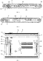
- the double-sided display device When the double-sided display device is in the normal display state, the flat part of the first flexible screen 2 on the front side of the housing 1 is exposed and used to display images (as shown in FIG. 1 ), while the second flexible screen 3 on the rear side of the housing 1 is not exposed out of the housing 1, that is, the second flexible screen 3 is shaded by the first housing 11 and the second housing 12 (as shown in FIG. 10 ) and cannot display images.
- the double-sided display device When the double-sided display device is in the extended display state, the flat part of the first flexible screen 2 on the front side of the housing 1 and a part of the winding part are both exposed out of the housing 1 and used to display images (as shown in FIG. 11 ). In this case, the display area is larger, and the part of the second flexible screen 3 on the rear side of the housing 1 is not exposed out of the housing 1, and can be used to display images (as shown in FIG. 12 ), which increases the display area of the double-sided display device.
- the display area of the double-sided display device is between the display area in the normal display state and the display area in the extended display state.
- the second housing 12 When it is necessary to control the double-sided display device to change from a normal display state to an extended display state, the second housing 12 is driven to slide away from the first housing 11 first, so that the second housing 12 can pull the second flexible screen 3 to extend, which is, to pull the winding part of the second flexible screen 3 to unwind, and meanwhile, drive the winding parts of the first flexible screen 2 and the second flexible screen 3 to unwind through the flexible screen drive part 5, so that a second part of the first flexible screen 2 is extended.
- the action of the flexible screen drive part 5 may be stopped at any time to obtain a corresponding display area of the first flexible screen 2 and a corresponding display area of the second flexible screen 3 as needed.
- the second housing 12 can be manually pulled by a user to slide relative to the first housing 11, and the second housing 12 can also be driven to slide relative to the first housing 11 by a driver, which is not limited in this embodiment.
- double-sided display of the double-sided display device is implemented by arranging the first flexible screen 2 and the second flexible screen 3 on the front and rear sides of the housing 1 respectively, so that the display area of the double-sided display device is increased; the winding part of the first flexible screen 2 and the second flexible screen 3 are driven to wind and unwind by the housing drive part 5, so that the display area of the double-sided display device can be controlled, and thus, the display area of the double-sided display device can have various situations, which improves the flexibility of adjusting the display area of the double-sided display device, enlarges an application range of the double-sided display device, and is convenient for users to use.
- the double-sided display device may also include a braced frame 9 located in the housing 1, the braced frame 9 is configured for bracing the first flexible screen 2 and the second flexible screen 3, so as to prevent the first flexible screen 2 and the second flexible screen 3 from being excessively bent to affect the use.
- one end of the first flexible screen 2 is wound in the first housing 11.
- the two ends of the first flexible screen 2 are both provided with a winding part, and one winding part is wound in the first housing 11, and the other winding part is wound in the second housing 12.
- the two winding parts of the first flexible screen can be extended at the same time, or one of the two winding parts of the first flexible screen 2 is extended and the other one is kept in a wound state, which is not limited in this embodiment.
- the double-sided display device further includes a housing drive part 4 configured for driving the housing 1 to extend.
- the housing drive part 4 is fixedly connected with the second housing 12 and is configured for driving the second housing 12 to slide relative to the first housing 11.
- the housing drive part 4 can drive the second housing 12 to slide close to or away from the first housing 11.
- the housing drive part 4 may include a housing drive motor 45 and a rack assembly driven to slide by the housing drive motor 45.
- the rack assembly is connected with the second housing 12.
- the housing drive motor 45 drives the rack assembly to move
- the rack assembly can drive the second housing 12 to slide relative to the first housing 11.
- the rack assembly includes a fixed seat 41, a first rack 42, a second rack 43 and a gear 44 meshed with the first rack 42 and the second rack 43 simultaneously.
- the fixed seat 41 is fixed to the first housing 11
- the first rack 42 and the second rack 43 are both slidably arranged on the fixed seat 41
- the second rack 43 is connected with the second housing 12.
- the first rack 42 slides in a first direction
- the second rack 43 can be driven by the gear 44 to slide in a second direction, so that the second rack 43 drives the second housing 12 to slide in the second direction, and then the second flexible screen 3 can be extended or contracted.
- the second direction is opposite to the first direction. For example, in FIG.
- the fixed seat 41 may be provided with a slide track
- bottoms of the first rack 42 and the second rack 43 may be provided with runners which can be slidably arranged on the slide track, so as to realize the sliding of the first rack 42 and the second rack 43 relative to the fixed seat 41, and the slide track can also guide a slide direction of the first rack 42 and the second rack 43.
- the flexible screen drive part 5 may include two first roll shafts 51 and a flexible screen drive motor 52 for driving the two first roll shafts 51 to rotate. Two ends of the first flexible screen 2 (i.e., two winding parts of the first flexible screen 2) are wound on the two first roll shafts 51 respectively. When the first roll shaft 51 rotates in a first rotation direction, winding of the winding part of the first flexible screen 2 can be realized. When the first roll shaft 51 rotates in a direction opposite the first rotation direction, unwinding of the winding part of the first flexible screen 2 can be realized.
- an outer surface of the first roller shaft 51 may be circumferentially provided with a plurality of bulges to better wind up the first flexible screen 2.
- the first roll shaft 51 is rotatably connected to the first housing 11, so that one end of the first flexible screen 2 is connected to the first housing 11 through the first roll shaft 51.
- the flexible screen drive motor 52 can be connected with the first roll shaft 51 through a conversion structure.
- the conversion structure is respectively connected with a telescopic end of the flexible screen drive motor 52 and the first roll shaft 51, and is configured for converting linear displacement generated by the telescopic end into rotation.
- the conversion structure when the telescopic end is extended, the conversion structure can drive the first roll shaft 51 to rotate in the first rotation direction, and when the telescopic end is retracted, the conversion structure can drive the first roll shaft 51 to rotate in the direction opposite to the first rotation direction.
- the conversion structure may be a gear structure with teeth inside and outside, and the telescopic end may be a rack.
- the flexible screen drive part 5 may further include a second roll shaft 53.
- the other end of the second flexible screen 3 i.e., the winding part of the second flexible screen 3
- the flexible screen drive motor 52 is further configured for driving the second roll shaft 53 to rotate, so that the second flexible screen 3 is extended or contracted.
- an outer surface of the second roll shaft 53 may be circumferentially provided with a plurality of bulges to better wind up the second roll shaft 53.
- the second roll shaft 53 is located between the two first roll shafts 51.
- the second roll shaft 53 is rotatably arranged on the second housing 12.
- the flexible screen drive part 5 may also include a roller 54.
- the roller 54 is located between the first flexible screen 2 and the second flexible screen 3, and teeth 541 are evenly distributed on an outer side of the roller 54 in a circumferential direction.
- An inner side of the first flexible screen 2 (that is, the opposite side of the first display surface) is provided with a plurality of first tooth sockets 21, and the teeth 541 can be meshed with the first tooth sockets 21.
- the flexible screen drive motor 52 is further configured for driving the roller 54 to rotate, so that when the roller 54 rotates, the first flexible screen 2 can be driven to move by the teeth 541 and the first tooth sockets 21 which are meshed with each other.
- the first flexible screen 2 when the roller 54 rotates along the first rotation direction, the first flexible screen 2 can be driven to move along the first direction. In this case, one winding part of the first flexible screen 2 is unwound.
- the first flexible screen 2 When the roller 54 rotates along a second rotation direction, the first flexible screen 2 can be driven to move along the second direction. In this case, the other winding part of the first flexible screen 2 is unwound.
- the inner side of the first display screen 2 is provided with a plurality of bulge structures, and the plurality of bulge structures is arranged at intervals, and the first tooth socket 21 is formed between two adjacent bulge structures.
- the flexible screen drive part 5 may include a plurality of rollers 54 to improve the stability and reliability when the rollers 54 drive the first flexible screen 2 to move.
- the inner side of the second flexible screen 3 may be provided with a plurality of second tooth sockets, and the teeth 541 can be meshed with the second tooth sockets.
- the roller 54 can also assist the second housing 12 to drive the second flexible screen 3 to move, so as to ensure that the second flexible screen 3 can be extended or contracted.
- the double-sided display device further includes an elastic structure and two fixing structures 7.
- the elastic structure 6 and the two fixing structures 7 are all located between the first flexible screen 2 and the second flexible screen 3, and, two ends and a middle of the elastic structure 6 are spiral, and one end of the elastic structure 6 is arranged on the first flexible screen 2 through one of the fixing structures 7, and the other end of the elastic structure 6 is arranged on the second flexible screen 3 through the other of the fixing structures 7.
- the elastic structure 6 is configured for elastically bracing the first flexible screen 2 and the second flexible screen 3.
- the elastic structure 6 can also control the strength and toughness during extending, and prevent the first flexible screen 2 and the second flexible screen 3 from being damaged due to quick bounce.
- the double-sided display device further includes a control switch 8 fixed on the housing 1.
- the control switch 8 is connected with the housing drive motor 45 and the flexible screen drive motor 52 respectively, and is configured for controlling the housing drive motor 45 and the flexible screen drive motor 52 to be enabled and stopped.
- the control switch may be connected with the housing drive motor 45 and the flexible screen drive motor 52 in a wired or wireless manner, or the control switch may also be connected with the printed circuit board 45 and the flexible screen drive motor 52 through a printed circuit board.
Landscapes
- Engineering & Computer Science (AREA)
- Theoretical Computer Science (AREA)
- Computer Hardware Design (AREA)
- Physics & Mathematics (AREA)
- General Engineering & Computer Science (AREA)
- General Physics & Mathematics (AREA)
- Human Computer Interaction (AREA)
- Mathematical Physics (AREA)
- Devices For Indicating Variable Information By Combining Individual Elements (AREA)
- Signal Processing (AREA)
Applications Claiming Priority (2)
| Application Number | Priority Date | Filing Date | Title |
|---|---|---|---|
| CN202010590544.3A CN111710241B (zh) | 2020-06-24 | 2020-06-24 | 一种双面显示装置 |
| PCT/CN2020/132052 WO2021258633A1 (fr) | 2020-06-24 | 2020-11-27 | Appareil d'affichage double face |
Publications (3)
| Publication Number | Publication Date |
|---|---|
| EP4006887A1 true EP4006887A1 (fr) | 2022-06-01 |
| EP4006887A4 EP4006887A4 (fr) | 2022-11-16 |
| EP4006887B1 EP4006887B1 (fr) | 2025-04-09 |
Family
ID=72542718
Family Applications (1)
| Application Number | Title | Priority Date | Filing Date |
|---|---|---|---|
| EP20942143.7A Active EP4006887B1 (fr) | 2020-06-24 | 2020-11-27 | Appareil d'affichage double face |
Country Status (4)
| Country | Link |
|---|---|
| US (1) | US20230135495A1 (fr) |
| EP (1) | EP4006887B1 (fr) |
| CN (1) | CN111710241B (fr) |
| WO (1) | WO2021258633A1 (fr) |
Families Citing this family (10)
| Publication number | Priority date | Publication date | Assignee | Title |
|---|---|---|---|---|
| CN111710241B (zh) * | 2020-06-24 | 2021-12-28 | 闻泰通讯股份有限公司 | 一种双面显示装置 |
| CN114495703B (zh) * | 2020-10-27 | 2024-07-02 | 北京小米移动软件有限公司 | 电子设备 |
| CN113063075B (zh) * | 2021-04-09 | 2023-03-28 | 昆山工研院新型平板显示技术中心有限公司 | 支撑结构件及显示装置 |
| CN115512606B (zh) * | 2021-06-22 | 2026-01-09 | 中兴通讯股份有限公司 | 用于显示装置的框架以及显示装置 |
| CN115529367B (zh) * | 2021-06-25 | 2025-08-26 | 北京小米移动软件有限公司 | 一种电子设备 |
| CN113570974B (zh) * | 2021-08-11 | 2022-07-08 | 闻泰通讯股份有限公司 | 柔性屏伸缩结构及电子设备 |
| CN114244930B (zh) * | 2021-12-17 | 2024-08-06 | 维沃移动通信有限公司 | 电子设备 |
| CN117203692B (zh) * | 2022-03-25 | 2026-01-23 | 京东方科技集团股份有限公司 | 显示装置 |
| CN117746735A (zh) * | 2023-11-24 | 2024-03-22 | 深圳市华星光电半导体显示技术有限公司 | 一种显示装置 |
| WO2026000431A1 (fr) * | 2024-06-28 | 2026-01-02 | 广州视源电子科技股份有限公司 | Dispositif d'affichage |
Family Cites Families (22)
| Publication number | Priority date | Publication date | Assignee | Title |
|---|---|---|---|---|
| KR101107127B1 (ko) * | 2010-01-12 | 2012-01-31 | 주식회사 다이아벨 | 이동 단말기 |
| US9383775B2 (en) * | 2012-02-07 | 2016-07-05 | Lg Electronics Inc. | Icon display method for a pull-out display device |
| CN203759584U (zh) * | 2013-12-20 | 2014-08-06 | 昆山国显光电有限公司 | 双面显示装置及便携式电子设备 |
| KR101669422B1 (ko) * | 2015-07-24 | 2016-10-26 | 이피네트시스템즈 주식회사 | 곡면형 디스플레이의 제조방법 |
| CN108322571B (zh) * | 2015-12-29 | 2020-07-14 | Oppo广东移动通信有限公司 | 一种移动终端 |
| CN206584684U (zh) * | 2016-12-28 | 2017-10-24 | 深圳市柔宇科技有限公司 | 柔性显示装置 |
| CN106875846A (zh) * | 2016-12-30 | 2017-06-20 | 深圳天珑无线科技有限公司 | 一种柔性屏的调整机构以及柔性显示装置 |
| CN109388270A (zh) * | 2017-08-11 | 2019-02-26 | 深圳天珑无线科技有限公司 | 一种具有柔性屏的终端 |
| KR102504138B1 (ko) * | 2018-01-04 | 2023-03-02 | 삼성디스플레이 주식회사 | 롤러블 표시 장치 |
| WO2019173940A1 (fr) * | 2018-03-12 | 2019-09-19 | 深圳市柔宇科技有限公司 | Ensemble de flexion et dispositif d'affichage souple |
| CN207968583U (zh) * | 2018-03-14 | 2018-10-12 | 上海和辉光电有限公司 | 一种双面屏手机 |
| KR102501909B1 (ko) * | 2018-04-20 | 2023-02-20 | 엘지디스플레이 주식회사 | 디스플레이 장치 |
| CN108597381A (zh) * | 2018-07-24 | 2018-09-28 | Oppo广东移动通信有限公司 | 一种显示屏以及具有该显示屏的电子装置 |
| CN109147571A (zh) * | 2018-09-29 | 2019-01-04 | 京东方科技集团股份有限公司 | 一种显示装置 |
| CN109859635A (zh) * | 2019-03-26 | 2019-06-07 | 云谷(固安)科技有限公司 | 一种卷曲显示装置 |
| KR102690763B1 (ko) * | 2019-03-29 | 2024-08-02 | 삼성디스플레이 주식회사 | 표시 장치 |
| CN110246422B (zh) * | 2019-07-25 | 2019-11-15 | 武汉华星光电半导体显示技术有限公司 | 一种柔性显示装置 |
| CN110491289B (zh) * | 2019-07-29 | 2024-03-15 | 武汉华星光电半导体显示技术有限公司 | 显示装置 |
| CN110868486B (zh) * | 2019-11-11 | 2022-03-01 | 京东方科技集团股份有限公司 | 一种显示装置及其使用方法 |
| CN112991928B (zh) * | 2019-12-13 | 2022-08-16 | Oppo广东移动通信有限公司 | 电子装置 |
| CN111309103B (zh) * | 2020-03-23 | 2021-12-10 | 合肥联宝信息技术有限公司 | 一种电子设备 |
| CN111710241B (zh) * | 2020-06-24 | 2021-12-28 | 闻泰通讯股份有限公司 | 一种双面显示装置 |
-
2020
- 2020-06-24 CN CN202010590544.3A patent/CN111710241B/zh active Active
- 2020-11-27 US US17/913,180 patent/US20230135495A1/en not_active Abandoned
- 2020-11-27 WO PCT/CN2020/132052 patent/WO2021258633A1/fr not_active Ceased
- 2020-11-27 EP EP20942143.7A patent/EP4006887B1/fr active Active
Also Published As
| Publication number | Publication date |
|---|---|
| CN111710241B (zh) | 2021-12-28 |
| CN111710241A (zh) | 2020-09-25 |
| WO2021258633A1 (fr) | 2021-12-30 |
| EP4006887B1 (fr) | 2025-04-09 |
| EP4006887A4 (fr) | 2022-11-16 |
| US20230135495A1 (en) | 2023-05-04 |
Similar Documents
| Publication | Publication Date | Title |
|---|---|---|
| EP4006887A1 (fr) | Appareil d'affichage double face | |
| US11343361B2 (en) | Mobile terminal, control system, and control method | |
| CN210181960U (zh) | 一种柔性显示装置和一种电子设备 | |
| US12426175B2 (en) | Rollable flexible display device and terminal equipment | |
| CN111510536B (zh) | 显示装置 | |
| CN110838264B (zh) | 显示装置 | |
| EP4362435A1 (fr) | Dispositif électronique | |
| CN112732021A (zh) | 电子设备 | |
| CN110322793B (zh) | 柔性显示装置 | |
| CN212627978U (zh) | 显示装置 | |
| CN113067915A (zh) | 移动终端 | |
| CN112991928A (zh) | 电子装置 | |
| WO2020206924A1 (fr) | Appareil d'affichage flexible et dispositif d'affichage électronique | |
| CN112991927A (zh) | 电子装置 | |
| CN112951085A (zh) | 电子装置 | |
| CN113890915A (zh) | 电子装置 | |
| CN107765502B (zh) | 投影屏幕装置 | |
| CN215068990U (zh) | 一种电子设备 | |
| CN216086703U (zh) | 电子装置 | |
| CN112967597A (zh) | 电子装置 | |
| CN213025137U (zh) | 一种调整机构及柔性显示装置 | |
| CN112995371A (zh) | 移动终端 | |
| CN116847010A (zh) | 伸缩屏组件以及终端设备 | |
| CN115132078B (zh) | 柔性屏设备 | |
| WO2023226982A1 (fr) | Dispositif électronique |
Legal Events
| Date | Code | Title | Description |
|---|---|---|---|
| STAA | Information on the status of an ep patent application or granted ep patent |
Free format text: STATUS: THE INTERNATIONAL PUBLICATION HAS BEEN MADE |
|
| PUAI | Public reference made under article 153(3) epc to a published international application that has entered the european phase |
Free format text: ORIGINAL CODE: 0009012 |
|
| STAA | Information on the status of an ep patent application or granted ep patent |
Free format text: STATUS: REQUEST FOR EXAMINATION WAS MADE |
|
| 17P | Request for examination filed |
Effective date: 20220223 |
|
| AK | Designated contracting states |
Kind code of ref document: A1 Designated state(s): AL AT BE BG CH CY CZ DE DK EE ES FI FR GB GR HR HU IE IS IT LI LT LU LV MC MK MT NL NO PL PT RO RS SE SI SK SM TR |
|
| A4 | Supplementary search report drawn up and despatched |
Effective date: 20221017 |
|
| RIC1 | Information provided on ipc code assigned before grant |
Ipc: H04M 1/02 20060101ALI20221011BHEP Ipc: G06F 1/16 20060101ALI20221011BHEP Ipc: G09F 9/30 20060101AFI20221011BHEP |
|
| DAV | Request for validation of the european patent (deleted) | ||
| DAX | Request for extension of the european patent (deleted) | ||
| GRAP | Despatch of communication of intention to grant a patent |
Free format text: ORIGINAL CODE: EPIDOSNIGR1 |
|
| STAA | Information on the status of an ep patent application or granted ep patent |
Free format text: STATUS: GRANT OF PATENT IS INTENDED |
|
| INTG | Intention to grant announced |
Effective date: 20241104 |
|
| GRAS | Grant fee paid |
Free format text: ORIGINAL CODE: EPIDOSNIGR3 |
|
| GRAA | (expected) grant |
Free format text: ORIGINAL CODE: 0009210 |
|
| STAA | Information on the status of an ep patent application or granted ep patent |
Free format text: STATUS: THE PATENT HAS BEEN GRANTED |
|
| AK | Designated contracting states |
Kind code of ref document: B1 Designated state(s): AL AT BE BG CH CY CZ DE DK EE ES FI FR GB GR HR HU IE IS IT LI LT LU LV MC MK MT NL NO PL PT RO RS SE SI SK SM TR |
|
| REG | Reference to a national code |
Ref country code: GB Ref legal event code: FG4D |
|
| REG | Reference to a national code |
Ref country code: CH Ref legal event code: EP |
|
| REG | Reference to a national code |
Ref country code: DE Ref legal event code: R096 Ref document number: 602020049364 Country of ref document: DE |
|
| REG | Reference to a national code |
Ref country code: IE Ref legal event code: FG4D |
|
| REG | Reference to a national code |
Ref country code: NL Ref legal event code: MP Effective date: 20250409 |
|
| PG25 | Lapsed in a contracting state [announced via postgrant information from national office to epo] |
Ref country code: NL Free format text: LAPSE BECAUSE OF FAILURE TO SUBMIT A TRANSLATION OF THE DESCRIPTION OR TO PAY THE FEE WITHIN THE PRESCRIBED TIME-LIMIT Effective date: 20250409 |
|
| REG | Reference to a national code |
Ref country code: AT Ref legal event code: MK05 Ref document number: 1784276 Country of ref document: AT Kind code of ref document: T Effective date: 20250409 |
|
| PG25 | Lapsed in a contracting state [announced via postgrant information from national office to epo] |
Ref country code: ES Free format text: LAPSE BECAUSE OF FAILURE TO SUBMIT A TRANSLATION OF THE DESCRIPTION OR TO PAY THE FEE WITHIN THE PRESCRIBED TIME-LIMIT Effective date: 20250409 Ref country code: PT Free format text: LAPSE BECAUSE OF FAILURE TO SUBMIT A TRANSLATION OF THE DESCRIPTION OR TO PAY THE FEE WITHIN THE PRESCRIBED TIME-LIMIT Effective date: 20250811 Ref country code: FI Free format text: LAPSE BECAUSE OF FAILURE TO SUBMIT A TRANSLATION OF THE DESCRIPTION OR TO PAY THE FEE WITHIN THE PRESCRIBED TIME-LIMIT Effective date: 20250409 |
|
| REG | Reference to a national code |
Ref country code: LT Ref legal event code: MG9D |
|
| PG25 | Lapsed in a contracting state [announced via postgrant information from national office to epo] |
Ref country code: GR Free format text: LAPSE BECAUSE OF FAILURE TO SUBMIT A TRANSLATION OF THE DESCRIPTION OR TO PAY THE FEE WITHIN THE PRESCRIBED TIME-LIMIT Effective date: 20250710 Ref country code: NO Free format text: LAPSE BECAUSE OF FAILURE TO SUBMIT A TRANSLATION OF THE DESCRIPTION OR TO PAY THE FEE WITHIN THE PRESCRIBED TIME-LIMIT Effective date: 20250709 |
|
| PG25 | Lapsed in a contracting state [announced via postgrant information from national office to epo] |
Ref country code: PL Free format text: LAPSE BECAUSE OF FAILURE TO SUBMIT A TRANSLATION OF THE DESCRIPTION OR TO PAY THE FEE WITHIN THE PRESCRIBED TIME-LIMIT Effective date: 20250409 |
|
| PG25 | Lapsed in a contracting state [announced via postgrant information from national office to epo] |
Ref country code: BG Free format text: LAPSE BECAUSE OF FAILURE TO SUBMIT A TRANSLATION OF THE DESCRIPTION OR TO PAY THE FEE WITHIN THE PRESCRIBED TIME-LIMIT Effective date: 20250409 |
|
| PG25 | Lapsed in a contracting state [announced via postgrant information from national office to epo] |
Ref country code: HR Free format text: LAPSE BECAUSE OF FAILURE TO SUBMIT A TRANSLATION OF THE DESCRIPTION OR TO PAY THE FEE WITHIN THE PRESCRIBED TIME-LIMIT Effective date: 20250409 |
|
| PG25 | Lapsed in a contracting state [announced via postgrant information from national office to epo] |
Ref country code: AT Free format text: LAPSE BECAUSE OF FAILURE TO SUBMIT A TRANSLATION OF THE DESCRIPTION OR TO PAY THE FEE WITHIN THE PRESCRIBED TIME-LIMIT Effective date: 20250409 |
|
| PG25 | Lapsed in a contracting state [announced via postgrant information from national office to epo] |
Ref country code: RS Free format text: LAPSE BECAUSE OF FAILURE TO SUBMIT A TRANSLATION OF THE DESCRIPTION OR TO PAY THE FEE WITHIN THE PRESCRIBED TIME-LIMIT Effective date: 20250709 |
|
| PG25 | Lapsed in a contracting state [announced via postgrant information from national office to epo] |
Ref country code: IS Free format text: LAPSE BECAUSE OF FAILURE TO SUBMIT A TRANSLATION OF THE DESCRIPTION OR TO PAY THE FEE WITHIN THE PRESCRIBED TIME-LIMIT Effective date: 20250809 |
|
| PG25 | Lapsed in a contracting state [announced via postgrant information from national office to epo] |
Ref country code: LV Free format text: LAPSE BECAUSE OF FAILURE TO SUBMIT A TRANSLATION OF THE DESCRIPTION OR TO PAY THE FEE WITHIN THE PRESCRIBED TIME-LIMIT Effective date: 20250409 |
|
| REG | Reference to a national code |
Ref country code: DE Ref legal event code: R097 Ref document number: 602020049364 Country of ref document: DE |
|
| PG25 | Lapsed in a contracting state [announced via postgrant information from national office to epo] |
Ref country code: DK Free format text: LAPSE BECAUSE OF FAILURE TO SUBMIT A TRANSLATION OF THE DESCRIPTION OR TO PAY THE FEE WITHIN THE PRESCRIBED TIME-LIMIT Effective date: 20250409 Ref country code: SM Free format text: LAPSE BECAUSE OF FAILURE TO SUBMIT A TRANSLATION OF THE DESCRIPTION OR TO PAY THE FEE WITHIN THE PRESCRIBED TIME-LIMIT Effective date: 20250409 |
|
| PG25 | Lapsed in a contracting state [announced via postgrant information from national office to epo] |
Ref country code: CZ Free format text: LAPSE BECAUSE OF FAILURE TO SUBMIT A TRANSLATION OF THE DESCRIPTION OR TO PAY THE FEE WITHIN THE PRESCRIBED TIME-LIMIT Effective date: 20250409 |
|
| PG25 | Lapsed in a contracting state [announced via postgrant information from national office to epo] |
Ref country code: EE Free format text: LAPSE BECAUSE OF FAILURE TO SUBMIT A TRANSLATION OF THE DESCRIPTION OR TO PAY THE FEE WITHIN THE PRESCRIBED TIME-LIMIT Effective date: 20250409 |
|
| PG25 | Lapsed in a contracting state [announced via postgrant information from national office to epo] |
Ref country code: RO Free format text: LAPSE BECAUSE OF FAILURE TO SUBMIT A TRANSLATION OF THE DESCRIPTION OR TO PAY THE FEE WITHIN THE PRESCRIBED TIME-LIMIT Effective date: 20250409 Ref country code: SK Free format text: LAPSE BECAUSE OF FAILURE TO SUBMIT A TRANSLATION OF THE DESCRIPTION OR TO PAY THE FEE WITHIN THE PRESCRIBED TIME-LIMIT Effective date: 20250409 |
|
| PG25 | Lapsed in a contracting state [announced via postgrant information from national office to epo] |
Ref country code: IT Free format text: LAPSE BECAUSE OF FAILURE TO SUBMIT A TRANSLATION OF THE DESCRIPTION OR TO PAY THE FEE WITHIN THE PRESCRIBED TIME-LIMIT Effective date: 20250409 |
|
| PLBE | No opposition filed within time limit |
Free format text: ORIGINAL CODE: 0009261 |
|
| STAA | Information on the status of an ep patent application or granted ep patent |
Free format text: STATUS: NO OPPOSITION FILED WITHIN TIME LIMIT |
|
| REG | Reference to a national code |
Ref country code: CH Ref legal event code: L10 Free format text: ST27 STATUS EVENT CODE: U-0-0-L10-L00 (AS PROVIDED BY THE NATIONAL OFFICE) Effective date: 20260218 |
|
| 26N | No opposition filed |
Effective date: 20260112 |