EP4006891A1 - Procédé d'attaque de rétroéclairage, procédé d'attaque d'affichage, dispositif d'attaque et dispositif d'affichage - Google Patents
Procédé d'attaque de rétroéclairage, procédé d'attaque d'affichage, dispositif d'attaque et dispositif d'affichage Download PDFInfo
- Publication number
- EP4006891A1 EP4006891A1 EP19931498.0A EP19931498A EP4006891A1 EP 4006891 A1 EP4006891 A1 EP 4006891A1 EP 19931498 A EP19931498 A EP 19931498A EP 4006891 A1 EP4006891 A1 EP 4006891A1
- Authority
- EP
- European Patent Office
- Prior art keywords
- backlight
- display
- control signals
- blocks
- frame
- Prior art date
- Legal status (The legal status is an assumption and is not a legal conclusion. Google has not performed a legal analysis and makes no representation as to the accuracy of the status listed.)
- Pending
Links
Images
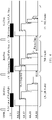

Classifications
-
- G—PHYSICS
- G09—EDUCATION; CRYPTOGRAPHY; DISPLAY; ADVERTISING; SEALS
- G09G—ARRANGEMENTS OR CIRCUITS FOR CONTROL OF INDICATING DEVICES USING STATIC MEANS TO PRESENT VARIABLE INFORMATION
- G09G3/00—Control arrangements or circuits, of interest only in connection with visual indicators other than cathode-ray tubes
- G09G3/20—Control arrangements or circuits, of interest only in connection with visual indicators other than cathode-ray tubes for presentation of an assembly of a number of characters, e.g. a page, by composing the assembly by combination of individual elements arranged in a matrix no fixed position being assigned to or needed to be assigned to the individual characters or partial characters
- G09G3/34—Control arrangements or circuits, of interest only in connection with visual indicators other than cathode-ray tubes for presentation of an assembly of a number of characters, e.g. a page, by composing the assembly by combination of individual elements arranged in a matrix no fixed position being assigned to or needed to be assigned to the individual characters or partial characters by control of light from an independent source
- G09G3/3406—Control of illumination source
- G09G3/342—Control of illumination source using several illumination sources separately controlled corresponding to different display panel areas, e.g. along one dimension such as lines
- G09G3/3426—Control of illumination source using several illumination sources separately controlled corresponding to different display panel areas, e.g. along one dimension such as lines the different display panel areas being distributed in two dimensions, e.g. matrix
-
- G—PHYSICS
- G09—EDUCATION; CRYPTOGRAPHY; DISPLAY; ADVERTISING; SEALS
- G09G—ARRANGEMENTS OR CIRCUITS FOR CONTROL OF INDICATING DEVICES USING STATIC MEANS TO PRESENT VARIABLE INFORMATION
- G09G2300/00—Aspects of the constitution of display devices
- G09G2300/04—Structural and physical details of display devices
- G09G2300/0421—Structural details of the set of electrodes
- G09G2300/0426—Layout of electrodes and connections
-
- G—PHYSICS
- G09—EDUCATION; CRYPTOGRAPHY; DISPLAY; ADVERTISING; SEALS
- G09G—ARRANGEMENTS OR CIRCUITS FOR CONTROL OF INDICATING DEVICES USING STATIC MEANS TO PRESENT VARIABLE INFORMATION
- G09G2310/00—Command of the display device
- G09G2310/02—Addressing, scanning or driving the display screen or processing steps related thereto
- G09G2310/024—Scrolling of light from the illumination source over the display in combination with the scanning of the display screen
-
- G—PHYSICS
- G09—EDUCATION; CRYPTOGRAPHY; DISPLAY; ADVERTISING; SEALS
- G09G—ARRANGEMENTS OR CIRCUITS FOR CONTROL OF INDICATING DEVICES USING STATIC MEANS TO PRESENT VARIABLE INFORMATION
- G09G2310/00—Command of the display device
- G09G2310/06—Details of flat display driving waveforms
-
- G—PHYSICS
- G09—EDUCATION; CRYPTOGRAPHY; DISPLAY; ADVERTISING; SEALS
- G09G—ARRANGEMENTS OR CIRCUITS FOR CONTROL OF INDICATING DEVICES USING STATIC MEANS TO PRESENT VARIABLE INFORMATION
- G09G2310/00—Command of the display device
- G09G2310/06—Details of flat display driving waveforms
- G09G2310/067—Special waveforms for scanning, where no circuit details of the gate driver are given
-
- G—PHYSICS
- G09—EDUCATION; CRYPTOGRAPHY; DISPLAY; ADVERTISING; SEALS
- G09G—ARRANGEMENTS OR CIRCUITS FOR CONTROL OF INDICATING DEVICES USING STATIC MEANS TO PRESENT VARIABLE INFORMATION
- G09G2310/00—Command of the display device
- G09G2310/08—Details of timing specific for flat panels, other than clock recovery
-
- G—PHYSICS
- G09—EDUCATION; CRYPTOGRAPHY; DISPLAY; ADVERTISING; SEALS
- G09G—ARRANGEMENTS OR CIRCUITS FOR CONTROL OF INDICATING DEVICES USING STATIC MEANS TO PRESENT VARIABLE INFORMATION
- G09G2320/00—Control of display operating conditions
- G09G2320/02—Improving the quality of display appearance
- G09G2320/0209—Crosstalk reduction, i.e. to reduce direct or indirect influences of signals directed to a certain pixel of the displayed image on other pixels of said image, inclusive of influences affecting pixels in different frames or fields or sub-images which constitute a same image, e.g. left and right images of a stereoscopic display
-
- G—PHYSICS
- G09—EDUCATION; CRYPTOGRAPHY; DISPLAY; ADVERTISING; SEALS
- G09G—ARRANGEMENTS OR CIRCUITS FOR CONTROL OF INDICATING DEVICES USING STATIC MEANS TO PRESENT VARIABLE INFORMATION
- G09G2320/00—Control of display operating conditions
- G09G2320/02—Improving the quality of display appearance
- G09G2320/0257—Reduction of after-image effects
-
- G—PHYSICS
- G09—EDUCATION; CRYPTOGRAPHY; DISPLAY; ADVERTISING; SEALS
- G09G—ARRANGEMENTS OR CIRCUITS FOR CONTROL OF INDICATING DEVICES USING STATIC MEANS TO PRESENT VARIABLE INFORMATION
- G09G2320/00—Control of display operating conditions
- G09G2320/06—Adjustment of display parameters
- G09G2320/0626—Adjustment of display parameters for control of overall brightness
- G09G2320/064—Adjustment of display parameters for control of overall brightness by time modulation of the brightness of the illumination source
-
- G—PHYSICS
- G09—EDUCATION; CRYPTOGRAPHY; DISPLAY; ADVERTISING; SEALS
- G09G—ARRANGEMENTS OR CIRCUITS FOR CONTROL OF INDICATING DEVICES USING STATIC MEANS TO PRESENT VARIABLE INFORMATION
- G09G2320/00—Control of display operating conditions
- G09G2320/06—Adjustment of display parameters
- G09G2320/0686—Adjustment of display parameters with two or more screen areas displaying information with different brightness or colours
-
- G—PHYSICS
- G09—EDUCATION; CRYPTOGRAPHY; DISPLAY; ADVERTISING; SEALS
- G09G—ARRANGEMENTS OR CIRCUITS FOR CONTROL OF INDICATING DEVICES USING STATIC MEANS TO PRESENT VARIABLE INFORMATION
- G09G3/00—Control arrangements or circuits, of interest only in connection with visual indicators other than cathode-ray tubes
- G09G3/20—Control arrangements or circuits, of interest only in connection with visual indicators other than cathode-ray tubes for presentation of an assembly of a number of characters, e.g. a page, by composing the assembly by combination of individual elements arranged in a matrix no fixed position being assigned to or needed to be assigned to the individual characters or partial characters
- G09G3/22—Control arrangements or circuits, of interest only in connection with visual indicators other than cathode-ray tubes for presentation of an assembly of a number of characters, e.g. a page, by composing the assembly by combination of individual elements arranged in a matrix no fixed position being assigned to or needed to be assigned to the individual characters or partial characters using controlled light sources
- G09G3/30—Control arrangements or circuits, of interest only in connection with visual indicators other than cathode-ray tubes for presentation of an assembly of a number of characters, e.g. a page, by composing the assembly by combination of individual elements arranged in a matrix no fixed position being assigned to or needed to be assigned to the individual characters or partial characters using controlled light sources using electroluminescent panels
- G09G3/32—Control arrangements or circuits, of interest only in connection with visual indicators other than cathode-ray tubes for presentation of an assembly of a number of characters, e.g. a page, by composing the assembly by combination of individual elements arranged in a matrix no fixed position being assigned to or needed to be assigned to the individual characters or partial characters using controlled light sources using electroluminescent panels semiconductive, e.g. using light-emitting diodes [LED]
-
- G—PHYSICS
- G09—EDUCATION; CRYPTOGRAPHY; DISPLAY; ADVERTISING; SEALS
- G09G—ARRANGEMENTS OR CIRCUITS FOR CONTROL OF INDICATING DEVICES USING STATIC MEANS TO PRESENT VARIABLE INFORMATION
- G09G3/00—Control arrangements or circuits, of interest only in connection with visual indicators other than cathode-ray tubes
- G09G3/20—Control arrangements or circuits, of interest only in connection with visual indicators other than cathode-ray tubes for presentation of an assembly of a number of characters, e.g. a page, by composing the assembly by combination of individual elements arranged in a matrix no fixed position being assigned to or needed to be assigned to the individual characters or partial characters
- G09G3/34—Control arrangements or circuits, of interest only in connection with visual indicators other than cathode-ray tubes for presentation of an assembly of a number of characters, e.g. a page, by composing the assembly by combination of individual elements arranged in a matrix no fixed position being assigned to or needed to be assigned to the individual characters or partial characters by control of light from an independent source
- G09G3/36—Control arrangements or circuits, of interest only in connection with visual indicators other than cathode-ray tubes for presentation of an assembly of a number of characters, e.g. a page, by composing the assembly by combination of individual elements arranged in a matrix no fixed position being assigned to or needed to be assigned to the individual characters or partial characters by control of light from an independent source using liquid crystals
Definitions
- the embodiments of the present disclosure relate to a backlight driving method, a display driving method, a drive device and a display device.
- Each backlight block includes one or a plurality of light-emitting diodes (LEDs).
- LEDs light-emitting diodes
- the driving current of LEDs of backlight blocks corresponding to these parts is automatically adjusted to realize individual adjustment of the brightness of each block in the backlight unit, thereby improving the contrast of the display image.
- the backlight unit includes a plurality of backlight blocks arranged in an array, a plurality of switching channels and a plurality of output channels, the plurality of backlight blocks include a plurality of rows of backlight blocks, the plurality of switching channels are respectively connected with the plurality of rows of backlight blocks, and the plurality of switching channels are configured to respectively and correspondingly provide first driving signals for the plurality of rows of backlight blocks under control of switching control signals; the plurality of backlight blocks include a plurality of columns of backlight blocks, the plurality of output channels are respectively connected with the plurality of columns of backlight blocks, and the plurality of output channels are configured to respectively and correspondingly provide second driving signals for the plurality of columns of backlight blocks under control of output control signals; the plurality of backlight blocks are configured to emit light under control of the switching control signals and the output control signals of a same frame.
- the backlight driving method includes: receiving a frame of backlight data, wherein the frame of backlight data includes a plurality of first control signals, which are respectively applied to the plurality of switching channels and serve as the switching control signals, and includes a plurality of second control signal groups respectively corresponding to the plurality of first control signals, each of the plurality of second control signal groups includes a plurality of second control signals which are respectively applied to the plurality of output channels and serve as the output control signals, and the plurality of first control signals are modulated non-constant width pulse signals respectively; and driving the backlight unit to emit light by using the plurality of first control signals and the plurality of second control signal groups.
- a pulse width of each of the plurality of first control signals is equal to or greater than a maximum of pulse widths of the plurality of second control signals in a second control signal group corresponding to the each of the plurality of first control signals.
- the driving the backlight unit to emit light by using the plurality of first control signals and the plurality of second control signal groups includes: applying, during a scanning cycle corresponding to the frame of backlight data, the plurality of first control signals to the plurality of switching channels sequentially; and applying, during a time period of applying each of the plurality of first control signals, the plurality of second control signals in a second control signal group corresponding to the each of the plurality of first control signals to the plurality of output channels.
- a starting time point of each of the plurality of first control signals is fixed, a first time interval between the starting time points of adjacent first control signals is equal, and the first time interval is greater than a maximum pulse width of the plurality of first control signals.
- a count of the plurality of switching channels is N
- the first time interval is less than or equal to 1/N of a time duration of the scanning cycle
- N is an integer greater than 1.
- a starting time point of the first control signal of a first switching channel is fixed, and except for the first switching channel, a second time interval between a starting time point of the first control signal of each of the remaining switching channels and an ending time point of the first control signal of a previous switching channel related to the each of the remaining switching channels is equal.
- a count of the plurality of switching channels is N
- a sum of a maximum pulse width of the plurality of first control signals and the second time interval is equal to or less than 1/N of a time duration of the scanning cycle
- N is an integer greater than 1.
- the backlight driving method provided by some embodiments of the present disclosure further includes: receiving a next frame of backlight data during a scanning cycle of a current frame of backlight data.
- the display device includes a display panel and a backlight unit, the display panel includes a plurality of display blocks arranged in an array, the backlight unit includes a plurality of backlight blocks arranged in an array, a plurality of switching channels and a plurality of output channels, the plurality of backlight blocks are configured to respectively and correspondingly provide display light for the plurality of display blocks, the plurality of backlight blocks include a plurality of rows of backlight blocks, the plurality of switching channels are respectively connected with the plurality of rows of backlight blocks, and the plurality of switching channels are configured to respectively and correspondingly provide first driving signals for the plurality of rows of backlight blocks under control of switching control signals; the plurality of backlight blocks include a plurality of columns of backlight blocks, the plurality of output channels are respectively connected with the plurality of columns of backlight blocks, and the plurality of output channels are configured to respectively and correspondingly provide second driving signals for the plurality of columns of backlight
- the display driving method includes: obtaining a frame of backlight data according to image information of a frame of display image; and adopting the backlight driving method according to any one embodiment of the present disclosure to drive the backlight unit to emit light based on the frame of backlight data.
- the obtaining the frame of backlight data according to the image information of the frame of display image includes: obtaining a frame of display data according to the image information of the frame of display image, wherein the frame of display data includes display data of the plurality of display blocks; obtaining grayscale distribution information of each of the plurality of display blocks according to the display data of the plurality of display blocks; obtaining, according to the grayscale distribution information of each of the plurality of display blocks, a second control signal in backlight data of a backlight block corresponding to the each of the plurality of display blocks, and obtaining, according to a plurality of second control signals of each row of backlight blocks, a second control signal group corresponding to the each row of backlight blocks; and obtaining a pulse width of the first control signal of each of the plurality of switching channels according to pulse widths of the plurality of second control signals in the second control signal group corresponding to the each row of backlight blocks.
- the display driving method provided by some embodiments of the present disclosure further includes: upon driving the backlight unit to emit light based on the frame of backlight data, driving the display panel to display based on the frame of display data.
- the display driving method provided by some embodiments of the present disclosure further includes: receiving image information of a next frame of display image during a scanning cycle of a current frame of backlight data, and obtaining a next frame of backlight data according to the image information of the next frame of display image.
- At least one embodiment of the present disclosure further provides a drive device which is applicable to a display panel and a backlight unit for the display panel.
- the display panel includes a plurality of display blocks arranged in an array
- the backlight unit includes a plurality of backlight blocks arranged in an array, a plurality of switching channels and a plurality of output channels
- the plurality of backlight blocks are configured to respectively and correspondingly provide display light for the plurality of display blocks
- the plurality of backlight blocks include a plurality of rows of backlight blocks
- the plurality of switching channels are respectively connected with the plurality of rows of backlight blocks
- the plurality of switching channels are configured to respectively and correspondingly provide first driving signals for the plurality of rows of backlight blocks under control of switching control signals
- the plurality of backlight blocks include a plurality of columns of backlight blocks
- the plurality of output channels are respectively connected with the plurality of columns of backlight blocks
- the plurality of output channels are configured to respectively and correspondingly provide second driving signals for the
- the drive device includes: a backlight data obtaining unit and a backlight control unit, wherein the backlight data obtaining unit is configured to obtaining a frame of backlight data according to image information of a frame of display image, the frame of backlight data includes a plurality of first control signals which are respectively applied to the plurality of switching channels and serve as the switching control signals, and includes a plurality of second control signal groups respectively corresponding to the plurality of first control signals, each of the plurality of second control signal groups includes a plurality of second control signals which are respectively applied to the plurality of output channels and serve as the output control signals, and the plurality of first control signals are modulated non-constant width pulse signals respectively; and the backlight control unit is configured to receive the frame of backlight data and to drive the backlight unit to emit light by using the plurality of first control signals and the plurality of second control signal groups included in the frame of backlight data.
- the backlight control unit is configured to receive the frame of backlight data and to drive the backlight unit to emit light by using the plurality
- the drive device further includes a display data obtaining unit, the backlight data obtaining unit includes a second control signal obtaining unit and a first control signal obtaining unit;
- the display data obtaining unit is configured to obtain, according to the image information of the frame of display image, a frame of display data which includes display data of the plurality of display blocks, and to obtain, according to display data of the plurality of display blocks, grayscale distribution information of each of the plurality of display blocks;
- the second control signal obtaining unit is configured to obtain, according to the grayscale distribution information of each of the plurality of display blocks, a second control signal of a backlight block corresponding to this display block, and to obtain, according to a plurality of second control signals of each row of backlight blocks, a second control signal group corresponding to the each row of backlight blocks;
- the first control signal obtaining unit is configured to obtain a pulse width of the first control signal of each of the switching channels according to pulse widths of the plurality of second control signals in the
- a pulse width of each of the plurality of first control signals is equal to or greater than a maximum of pulse widths of the plurality of second control signals in a second control signal group corresponding to the each of the plurality of first control signals.
- the drive device provided by some embodiments of the present disclosure further includes: a display control unit, wherein the display control unit is configured to control the display panel to display based on the frame of display data upon the backlight control unit driving the backlight unit to emit light by using the plurality of first control signals and the plurality of second control signal groups.
- a display control unit configured to control the display panel to display based on the frame of display data upon the backlight control unit driving the backlight unit to emit light by using the plurality of first control signals and the plurality of second control signal groups.
- the display data obtaining unit is further configured to receive image information of a next frame of display image during a scanning cycle of a current frame of backlight data, and to obtain a next frame of display data according to the image information of the next frame of display image; and the backlight data obtaining unit is further configured to obtain a next frame of backlight data according to the image information of the next frame of display image during the scanning cycle of the current frame of backlight data.
- At least one embodiment of the present disclosure further provides a display device, including the display panel, the backlight unit and the drive device according to any one embodiment of the present disclosure, wherein the drive device is configured to control the backlight unit to emit light and control the display panel to display.
- a liquid crystal display (LCD) panel includes a liquid crystal panel and a backlight unit.
- the liquid crystal panel includes an array substrate and an opposite substrate (such as a color filter substrate) which are oppositely arranged to form a liquid crystal cell, and a liquid crystal layer is filled between the array substrate and the opposing substrate in the liquid crystal cell; a first polarizer is disposed on the array substrate; a second polarizer is disposed on the opposite substrate; and the polarization directions of the first polarizer and the second polarizer are perpendicular to each other.
- the backlight unit is disposed at a non-display side of the liquid crystal panel and configured to provide a planar source for the display of the liquid crystal panel.
- liquid crystal molecules of the liquid crystal layer are twisted. After the liquid crystal molecules are twisted by a predetermined angle, the polarization direction of light passing through the liquid crystal layer can be controlled, and the transmittance of the light can be controlled with the cooperation of the first polarizer and the second polarizer, thereby realizing grayscale display.
- the backlight unit may be a direct-lit backlight unit or a side-lit backlight unit.
- the direct-lit backlight unit or the side-lit backlight unit can include a plurality of point sources (such as LEDs) which are arranged in parallel and a diffuser plate. Light emitted from the point sources is homogenized by the diffuser plate and then incident into the liquid crystal panel for display.
- the side-lit backlight unit can adopt global dimming technology to realize the overall brightness adjustment of the backlight unit, and the direct-lit backlight unit can adopt a progressive lighting technique to realize the brightness adjustment of the backlight unit.
- high-resolution LCD panels have been gradually applied to virtual reality (VR) devices.
- VR virtual reality
- human eyes are closer to the display screen, and the display effect of a display image can be more easily perceived, so the requirements on the resolution and display quality of the display panel are getting higher and higher.
- the direct-lit backlight unit can be controlled by LD technology, so as to improve the display quality of the display panel to satisfy the requirement of the VR device on the display quality of the display panel.
- the LD technology can divide the entire backlight unit into a plurality of backlight blocks that can be driven individually.
- Each backlight block includes one or a plurality of LEDs.
- the driving current of LEDs of backlight blocks corresponding to these parts is automatically adjusted to realize individual adjustment of the brightness of each block in the backlight unit, thereby improving the contrast of the display image.
- the LD technology is merely applied to the direct-lit backlight unit, and a plurality of LEDs serving as light sources are, for instance, uniformly distributed in the entire back plate.
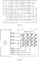
- FIG. 1A a schematic diagram of divided regions of LED sources in an entire back plate is as shown in FIG. 1A .
- a small square in the figure represents one LED unit, and a plurality of regions separated by dashed lines represent a plurality of backlight blocks.
- Each backlight block includes one or a plurality of LED units and can be controlled independent of other backlight blocks.
- the plurality of LEDs in each backlight block are connected in series. That is to say, the current running through the plurality of LEDs disposed in the same backlight block is consistent, so the luminescent brightness thereof is basically consistent.
- FIG. 1B is a schematic diagram of a drive architecture of a backlight unit.
- the backlight unit 100 includes a plurality of backlight blocks.
- FIG.1B only shows a backlight unit which includes backlight blocks of 4 rows and 4 columns, and each backlight block only includes one LED, but the present disclosure is not limited thereto.
- the backlight unit 100 can be driven by means of local dimming.
- the backlight unit 100 can further include switching channels MUX1-MUX4 connected with LEDs in a plurality of rows of backlight blocks and output channels CH1-CH4 connected with LEDs in a plurality of columns of backlight blocks.
- the switching channels MUX1-MUX4 are turned on under the control of switching control signals, so as to correspondingly provide first driving signals (for instance, at a high voltage) for the LEDs in the plurality of rows of backlight blocks; the output channels CH1-CH4 are turned on under the control of output control signals, so as to correspondingly provide second driving signals (for instance, at a low voltage) for the LEDs in the plurality of columns of backlight blocks; and the LEDs in each backlight block are applied with a corresponding driving voltage (for instance, the driving voltage is a difference voltage between the first driving signal and the second driving signal) via the switching channel and the output channel which are connected with the LEDs, so a corresponding driving current flows through the LEDs and the LEDs emit light.
- a corresponding driving voltage for instance, the driving voltage is a difference voltage between the first driving signal and the second driving signal
- the driving current outputted by the switching channels MUX1-MUX4 and the output channels CH1-CH4 can be obtained by a conventional algorithm in the prior art, and the turn-on time duration of the output channels CH1-CH4 can be obtained according to backlight data, thereby realizing local dimming.
- an LED driver 150 can provide the switching control signals for the switching channels MUX1-MUX4 and provide the output control signals for the output channels CH1-CH4, so as to drive the LEDs in the backlight blocks to emit light.
- the backlight data include width configuration parameters of the output control signals of the output channels CH1-CH4.
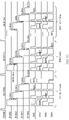
- FIG. 1C is a timing chart for driving backlight blocks.
- the timing sequence shown in FIG. 1C can be applied to the drive architecture shown in FIG. 1B .
- a frame-by-frame scanning can be performed on the backlight unit 100 under the control of a vertical synchronization signal Vsync.
- Each frame of backlight data corresponds to one scanning cycle, and the time duration of the scanning cycle is the reciprocal of the refresh rate of the vertical synchronization signal Vsync.
- the width (namely time duration) of each scanning cycle is 1/60 second (s), that is, approximately 16.67 millisecond (ms).
- the embodiments of the present disclosure are described by taking that the refresh rate is 60 Hz as an example, but the present disclosure is not limited to this case.
- the switching control signals are sequentially applied to the switching channels MUX1-MUX4, and meanwhile, the output control signals are provided to the output channels CH1-CH4 during the time period when each switching channel is turned on by the switching control signal, so as to realize the line-by-line scanning of the backlight blocks.
- the output control signals of the output channels CH1-CH4 are pulse width modulation (PWM) signals, and the pulse width of a PWM signal is determined by the width configuration parameter of the output control signal in the backlight data.
- the PWM signal can be a 12-bit digital signal with a value range of 0-4095, or the PWM signal can be an 8-bit digital signal with a value range of 0-4095.
- the embodiments of the present disclosure are described by taking that the value range of the PWM signal is 0-255 as an example, but the present disclosure is not limited to this case.
- the value of the PWM signal corresponds to the pulse width of the PWM signal.
- the PWM signal has a value of 1023 corresponds to that the PWM signal has a pulse width of 1,023 microseconds ( ⁇ s), and the PWM signal has a value of 2047 corresponds to that the PWM signal has a pulse width 2,047 ⁇ s.
- the maximum pulse width of the PWM signals is 4,096 ⁇ s, namely 4.096ms.
- the pulse widths of the switching control signals of the switching channels MUX-MUX4 should be equal to or greater than the maximum pulse width of the PWM signals, so as to ensure that each backlight block can emit light in full accordance with the PWM signals.
- the pulse widths of the switching control signals of the switching channels MUX-MUX4 are set to be a constant average equal width, for instance, slightly greater than the maximum pulse width 4.096ms of the PWM signals, for instance, about 4.1 ms (as shown in FIG. 1C ).
- the pulse widths of the switching control signals can be equal to the maximum pulse width of the PWM signals.
- channel interval there is an inter-channel time interval between the switching control signals of adjacent switching channels, which is referred to as channel interval (i.e., MUX Gap, as shown by the shaded areas in FIG. 1C )) for short.
- the MUX Gap is generally set to be a constant average equal width. Due to are parasitic capacitances of the LEDs and the like in each backlight block, after the switching channels of one row of backlight blocks are turned off, the parasitic capacitances in the row of backlight blocks are discharged, and the MUX Gap is used for ensuring complete discharge.
- the LEDs in the previous row of backlight blocks will not emit light due to the incomplete discharge of the parasitic capacitances.
- the width of the MUX Gap generally can only be on the magnitude of several ⁇ s or tens of ⁇ s. In practical application, due to the small width of the MUX Gap, image ghost and other problems caused by incomplete discharge are easy to occur.
- the response time of the liquid crystal molecules in the LCD panel (namely the time from the beginning of the twisting of the liquid crystal molecules to the ending of the twisting when the liquid crystal molecules are stabilized at a predetermined angle) is long, and for instance, even the liquid crystal molecules have a rapid response function, the response time thereof is still 4-5 ms, and therefore, a dynamic blur phenomenon is easy to occur in the display process of the display panel.
- black frame insertion technology e.g., inserting one full-black frame between two or more adjacent frames
- the direct-lit backlight unit usually adopts the driving method of illuminating the backlight blocks line by line, so that the black frame insertion technology is difficult to be applied thereto. Therefore, there is still no mature technology to solve the problems of dynamic blur and the like in the display process of the display device employing the direct-lit backlight unit.
- the backlight unit includes: a plurality of backlight blocks arranged in an array, a plurality of switching channels and a plurality of output channels.
- the plurality of backlight blocks include a plurality of rows of backlight blocks, the plurality of switching channels are respectively connected with the plurality of rows of backlight blocks, and the plurality of switching channels are configured to respectively and correspondingly provide first driving signals for the plurality of rows of backlight blocks under the control of switching control signals;
- the plurality of backlight blocks include a plurality of columns of backlight blocks, the plurality of output channels are respectively connected with the plurality of columns of backlight blocks, and the plurality of output channels are configured to respectively and correspondingly provide second driving signals for the plurality of columns of backlight blocks; and the plurality of backlight blocks are configured to emit light under the control of the switching control signals and the output control signals of a same frame.
- the backlight driving method includes: receiving a frame of backlight data, wherein the frame of backlight data includes a plurality of first control signals which are respectively applied to the plurality of switching channels and serve as the switching control signals, and includes a plurality of second control signal groups respectively corresponding to the plurality of first control signals, each of the plurality of second control signal groups includes a plurality of second control signals which are respectively applied to the plurality of output channels and serve as the output control signals, and the plurality of first control signals are modulated non-constant width pulse signals respectively; and driving the backlight unit to emit light by using the plurality of first control signals and the plurality of second control signal groups.
- Some embodiments of the present disclosure further provide a display driving method, a drive device and a display device corresponding to the foregoing backlight driving method.
- the backlight driving method, the display driving method, the drive device and the display device provided by at least one embodiment of the present disclosure can perform real-time configuration on the pulse widths of the switching control signals, thus can be used for increasing the time interval between adjacent switching control signals, so as to reduce the probability of the image ghost phenomenon, or can be used for increasing the time interval between adjacent frames in a probable way, so as to reduce the probability of the dynamic blur phenomenon.
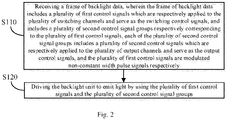
- FIG. 2 is a flowchart of a backlight driving method of a backlight unit provided by at least one embodiment of the present disclosure.
- FIG. 3 is a timing chart for driving backlight blocks according to a backlight driving method provided by some embodiments of the present disclosure.
- the backlight unit can be referred to the backlight unit as shown in FIG. 1A and FIG. 1B , without being limited in the embodiments of the present disclosure.
- the backlight unit includes a plurality of backlight blocks which are arranged in an array, a plurality of switching channels and a plurality of output channels.
- each backlight block of the backlight unit includes one or a plurality of LEDs, and for instance, mini-LEDs (e.g., manufactured on a silicon substrate, with a device dimension of 10-100 ⁇ m) can be adopted.
- the plurality of backlight blocks include a plurality of rows of backlight blocks
- the plurality of switching channels e.g., MUX1-MUX4 as shown in FIG. 1B
- the plurality of switching channels are respectively connected with the plurality of rows of backlight blocks
- the plurality of switching channels are configured to respectively and correspondingly provide first driving signals for the plurality of rows of backlight blocks under the control of switching control signals.
- the switching channels can be turned on by the switching control signals.
- the first driving signals are at a high voltage.
- the plurality of backlight blocks include a plurality of columns of backlight blocks, the plurality of output channels (e.g., CH1-CH4 as shown in FIG.
- the plurality of output channels are configured to respectively and correspondingly provide second driving signals for the plurality of columns of backlight blocks under the control of output control signals.
- the output channels can be turned on by the output control signals.
- the second driving signals are at a low voltage.
- the LEDs in each backlight block are applied with a corresponding driving voltage (for instance, the driving voltage is a difference voltage between the first driving signal and the second driving signal) via the switching channel and the output channel connected with the LEDs, so a corresponding driving current flows through the LEDs and the LEDs emit light.
- the plurality of backlight blocks are configured to emit light under the control of the switching control signals and the output control signals of a same frame. For instance, in the case where both the switching channel and the output channel related to a backlight block are turned on, a corresponding driving current is provided, so that the backlight block emits light (namely the LEDs in the backlight block emit light).
- the backlight driving method provided by the embodiments of the present disclosure will be described below by taking the backlight unit shown in FIG. 1B as an example and with reference to FIG. 2 and FIG. 3 . It should be understood that the backlight driving method provided by the embodiments of the present disclosure is not only applicable to the backlight unit shown in FIG. 1B . Therefore, although the backlight unit shown in FIG. 1B is taken as an example, it should not be regarded as a limitation to the present disclosure.
- the backlight driving method includes steps S110 to S120.
- Step S110 receiving a frame of backlight data, wherein the frame of backlight data includes a plurality of first control signals which are respectively applied to the plurality of switching channels and serve as the switching control signals, and includes a plurality of second control signal groups respectively corresponding to the plurality of first control signals, each of the plurality of second control signal groups includes a plurality of second control signals which are respectively applied to the plurality of output channels and serve as the output control signals, and the plurality of first control signals are modulated non-constant width pulse signals respectively.
- the frame of backlight data can be obtained according to image information of a frame of display image corresponding to the frame of backlight data.
- the second control signals in the second control signal groups can be obtained by a conventional algorithm in the prior art, and the first control signals can be obtained according to the second control signals in the second control signal groups corresponding thereto.
- the frame of backlight data can be received by, for instance, the LED driver 150 as shown in FIG. 1B , and stored in a storage unit, such as a register, of the LED driver 150 so as to be used in the subsequent step S120. It should be noted that the embodiments of the present disclosure include this case, but are not limited thereto.
- the timing sequences of the second control signals applied to the output channels CH1-CH4 as shown in FIG. 3 are the same as the timing sequences of the output control signals applied to the output channels CH1-CH4 as shown in FIG. 1C .
- the width configuration parameters of the second control signals in FIG. 3 and the width configuration parameters of the output control signal in FIG. 1C are obtained by the same algorithm according to the image information of the same display image.
- a pulse width of each first control signal is equal to or greater than the maximum of pulse widths of the plurality of second control signals in a second control signal group corresponding to the each first control signal.
- the pulse width (e.g., 3,071) of the first control signal of the switching channel CH1 is equal to the maximum (e.g., 3,071) of the pulse widths of the plurality of second control signals (namely the second control signals of the output channels CH1-CH4) in the corresponding second control signal group;
- the pulse width (e.g., 4,095) of the first control signal of the switching channel CH2 is equal to the maximum (e.g., 4,095) of the pulse widths of the plurality of second control signals (namely the second control signals of the output channels CH1-CH4) in the corresponding second control signal group;
- the pulse width (e.g., 3,071) of the first control signal of the switching channel CH1 is equal to the maximum (e.g., 3,071) of the pulse widths of the plurality of second control signals (namely the second control
- the pulse width (e.g., 1,023) of the first control signal of the switching channel CH4 is equal to the maximum (e.g., 1,023) of the pulse widths of the plurality of second control signals (namely the second control signals of the output channels CH1-CH4) in the corresponding second control signal group.
- the cases of the (N-1)th frame and the (N+1)th frame are similar to that of the Nth frame, and no further description will be given here. It should be noted that the unit of the pulse widths of the first control signals and the second control signals in FIG. 3 is ⁇ s, and the specific values are all illustrative without being limited in the embodiments of the present disclosure.
- the pulse width of the first control signal can also be set to be slightly greater than the maximum of the pulse widths of the plurality of second control signals in the corresponding second control signal group.
- the difference between the pulse width of the first control signal and the maximum of the pulse widths of the plurality of second control signals in the corresponding second control signal group is a constant value.
- the constant value is several ⁇ s or ten-odd ⁇ s or several tens of ⁇ s.
- the maximum of the pulse widths of the first control signals should not be too large.
- the maximum of the pulse widths of the first control signals should be at least less than 1/N of the time duration of the scanning cycle (for example, in the example as shown in FIG. 3 , the maximum should be at least less than 1/4 of the time duration of the scanning cycle), and N (N is an integer greater than 1) is the number of the switching channels, namely the number of rows of the plurality of rows of backlight blocks in the backlight unit.
- Step S120 driving the backlight unit to emit light by using the plurality of first control signals and the plurality of second control signal groups.
- the backlight unit can be driven to emit light by using, for instance, the LED driver 150 as shown in FIG. 1B .
- the embodiments of the present disclosure include this case, but are not limited thereto.
- step S120 can include: applying, during the scanning cycle corresponding to the frame of backlight data, the plurality of first control signals to the plurality of switching channels sequentially; and applying, during the time period of applying each first control signal, the plurality of second control signals in a second control signal group corresponding to the each first control signal to the plurality of output channels. For instance, as shown in FIG.
- corresponding first control signals are sequentially applied to the switching channels MUX1-MUX4; and meanwhile, during the time period when applying each first control signal corresponding to each switching channel, the plurality of second control signals in the second control signal group corresponding to the each first control signal are applied to the output channels CH1-CH4.
- the starting time points of the plurality of second control signals corresponding to the each first control signal can be the same, that is, the plurality of second control signals are synchronously applied.
- the starting time points of the plurality of second control signals corresponding to the each first control signal are also the same as the starting time point of the each first control signal, that is, the each first control signal and the plurality of second control signals corresponding to the each first control signal are synchronously applied. It should be noted that the embodiments of the present disclosure include the above cases but are not limited thereto.
- the starting time point of each first control signal is fixed, and a first time interval dt1 between the starting time points of adjacent first control signals is equal.
- the first time interval dt1 can also be constant.
- FIG. 1C the pulse width of each switching control signal is constant and equal, so the image ghost phenomenon caused by small time duration of the MUX Gap may occur; and in FIG. 3 , the pulse width of each first control signal is determined according to the pulse widths of the plurality of second control signals corresponding to the each first control signal, that is, each first control signal is a modulated signal. As shown in FIG.
- the MUX Gap between adjacent first control signals is variable (as shown by the shaded areas in FIG. 3 ).
- the width of the MUX Gap as shown in FIG. 3 is significantly increased in most cases. For instance, in some cases as shown in FIG. 3 , the width can be increased to be on the magnitude of several hundreds of ⁇ s and even ms. For instance, as shown in FIG.
- the width of the MUX Gap between the former first control signal and a latter first control signal (equal to the first time interval dt1 minus the pulse width of the former first control signal) is small; and in the case where the pulse width of the former first control signal is small, the width of the MUX Gap between the former first control signal and the latter first control signal is large.
- the pulse widths of the second control signals in each second control signal group will not reach the maximum, so the pulse width of the first control signal will also not reach the maximum.
- the width of the MUX Gap can be increased in a probable way, and then the probability of the image ghost phenomenon can be reduced.
- the first control signal of each switching channel corresponds to one first time interval, and in the case where the number of the plurality of switching channels is N, the first time interval dt1 should be less than or equal to 1/N of the time duration of the scanning cycle.
- the scanning of one frame of backlight data can be completed within one scanning cycle.
- the backlight driving method provided by the embodiment of the present disclosure further includes: receiving a next frame of backlight data during a scanning cycle of a current frame of backlight data.
- the Nth frame of backlight data is received during the scanning cycle of the (N-1)th frame; the (N+1)th frame of backlight data is received during the scanning cycle of the Nth frame; and the (N+2)th frame of backlight data is received during the scanning cycle of the (N+1)th frame.
- the next frame of backlight data can be transmitted to, for example, the LED driver 150 as shown in FIG. 1B through a serial peripheral interface (SPI), and stored into a storage unit, such as a register, of the LED driver 150, so as to be used in the subsequent scanning cycle of the next frame of backlight data.
- SPI serial peripheral interface
- the SPI only needs to transmit the width configuration parameters of the output control signals of the output channels.
- the SPI not only needs to transmit the width configuration parameters of the second control signals of the output channels, but also needs to transmit the width configuration parameters of the first control signals of the switching channels.
- the width configuration parameter of the first control signal of the switching channel is small in data size, and taking that the backlight unit includes 4 switching channels as an example, the SPI only needs to transmit 8 bytes more data, which has little effect on the processing speed of the SPI.
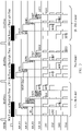
- FIG. 4 is a timing chart for driving backlight blocks according to another backlight driving method provided by some embodiments of the present disclosure.
- Other aspects of the backlight driving method corresponding to the timing chart shown in FIG. 4 are basically the same as those of the backlight driving method corresponding to the timing chart shown in FIG. 3 , and will not be repeated here. The difference mentioned above will be described in detail below with reference to FIG. 4 .
- the starting time point of the first control signal of the first switching channel MUX1 is fixed; and except for the first switching channel MUX1, a second time interval dt2 between the starting time point of the first control signal of each of the remaining switching channels (MUX2-MUX4) and the ending time point of the first control signal of a previous switching channel related to the each of the remaining switching channels is equal.
- the second time interval dt2 can also be constant.
- the second time interval dt2 is a MUX Gap. Therefore, the MUX Gap shown in FIG. 4 can be similar to the MUX Gap shown in FIG. 1C , and both have a constant average equal width.
- the width configuration parameter of the MUX Gap as shown in FIG. 4 can be referred to the width configuration parameter of the MUX Gap as shown in FIG. 1C , for instance, can be on the magnitude of several ⁇ s or tens of ⁇ s.
- the width of the second time interval dt2 should not be too large.
- the sum of the maximum of the pulse width of the first control signal and the second time interval dt2 should be less than or equal to 1/N of the time duration of the scanning cycle (for instance, in the example as shown in FIG. 4 , the maximum should be at least less than or equal to 1/4 of the time duration of the scanning cycle), and N is the number of the switching channels, namely the number of rows of the plurality of rows of backlight blocks in the backlight unit.
- the time interval between the ending time point of the first control signal of the last switching channel of a former frame and the starting time point of the first control signal of the first switching channel of a latter frame can be defined as the frame gap.
- the frame gap between adjacent frames is constant and has equal width.
- the frame gap between adjacent frames is modulated by the pulse width of the first control signal of the last switching channel of the former frame, but the variable range of the frame gap is relatively small.
- the frame gap between adjacent frames is modulated by the sum of the pulse widths of the first control signals of all the switching channels of the former frame, so the variable range of the frame gap is relatively large.
- the width of the frame gap between the former frame and the latter frame is small (as shown by the frame gap between the (N-1)th frame and the Nth frame in FIG.
- the pulse widths of the first control signals of the switching channels MUX1-MUX4 all reach the maximum (namely similar to the timing sequences in FIG. 1C ), and the frame gap between the (N-1)th frame and the Nth frame is basically the same as the frame gap in FIG. 1C .
- the (N-1)th frame in FIG. 4 shows an extreme case, and for most frames, the values of the pulse widths of the first control signals of the switching channels MUX1-MUX4 can be considered as random (namely rarely reaching the maximum value at the same time), and for instance, the cases for most frames can be referred to the case as shown by the Nth frame. In this case, as shown in FIG.
- the frame gap between the Nth frame and the (N+1)th frame is obviously increased compared with the frame gap in FIG. 1C . Therefore, it should be understood that in most cases, the backlight driving method corresponding to the timing chart shown in FIG. 4 can increase the width of the frame gap in a probable way, so as to achieve the effect similar to that of the black frame insertion technology (that is, the LEDs in the backlight unit do not emit light within a relatively wide frame gap), and further, the probability of the dynamic blur phenomenon can be reduced.
- the backlight driving method provided by the above embodiments of the present disclosure can at least partially be implemented in the form of software, hardware, firmware or any combination thereof.
- the backlight driving method can perform real-time configuration on the pulse widths of the switching control signals, which can be used for increasing the time interval between adjacent switching control signals, so as to reduce the probability of the image ghost phenomenon, or can be used for increasing the time interval between adjacent frames in a probable way, so as to reduce the probability of the dynamic blur phenomenon.
- FIG. 5 is a flowchart of the display driving method of a display device provided by at least one embodiment of the present disclosure.
- the display device includes a display panel and a backlight unit.
- the display panel includes a plurality of display blocks arranged in an array, and each display block includes one or a plurality of subpixels.
- the backlight unit includes a plurality of backlight blocks which are arranged in an array, a plurality of switching channels and a plurality of output channels.
- the plurality of display blocks are in one-to-one correspondence with the plurality of backlight blocks, and the plurality of backlight blocks are configured to respectively and correspondingly provide display light for the plurality of display blocks.
- that a display block corresponds to a backlight block can be understood as that the backlight block and the subpixels in the display block are overlapped in the orthographic projection direction.
- each backlight block of the backlight unit includes one or a plurality of LEDs, and for instance, mini-LEDs (e.g., with a device dimension of 10-100 ⁇ m) can be adopted.
- the backlight unit can be referred to the backlight unit as shown in FIG. 1A and FIG. 1B , without being limited in the embodiments of the present disclosure.
- the plurality of backlight blocks include a plurality of rows of backlight blocks
- the plurality of switching channels e.g., MUX1-MUX4 as shown in FIG. 1B
- the plurality of switching channels are respectively connected with the plurality of rows of backlight blocks
- the plurality of switching channels are configured to respectively and correspondingly provide first driving signals for the plurality of rows of backlight blocks under the control of switching control signals.
- the switching channels can be turned on by the switching control signals (namely the first control signals).
- the first driving signals are at a high voltage.
- the plurality of backlight blocks include a plurality of columns of backlight blocks
- the plurality of output channels e.g., CH1-CH4 as shown in FIG. 1B
- the plurality of output channels are respectively connected with the plurality of columns of backlight blocks
- the plurality of output channels are configured to respectively and correspondingly provide second driving signals for the plurality of columns of backlight blocks under the control of output control signals.
- the output channels can be turned on by the output control signals (namely the second control signals).
- the second driving signals are at a low voltage.
- the LEDs in each backlight block are applied with a corresponding driving voltage (for instance, the driving voltage is a difference voltage between the first driving signal and the second driving signal) via the switching channel and the output channel connected with the LEDs, so a corresponding driving current flows through the LEDs and the LEDs emit light.
- the first driving signal or the second driving signal can be at a fixed level, without being limited in the embodiment of the present disclosure.
- the plurality of backlight blocks are configured to emit light under the control of the switching control signals and the output control signals of a same frame. For instance, in the case where the switching channel and the output channel related to a backlight block are simultaneously turned on, the backlight block emits light (that is, the LEDs in the backlight block emit light).
- liquid crystal molecules in subpixels of the display panel begin to twist under the action of the driving electric field applied between the pixel electrodes of the subpixels and the common electrode(s), and the display panel performs a normal display after the liquid crystal molecules complete the twisting.
- the foregoing backlight driving method can be adopted to drive the backlight unit to emit light.
- one row of backlight blocks corresponding to this row of display blocks emit light, that is, the switching channels corresponding to this row of backlight blocks are turned on by the switching control signals (namely the first control signals), and meanwhile, the plurality of output channels are also respectively turned on by the output control signals (namely the second control signals).
- the display device can be an LCD device or an electronic paper display device, etc.
- the display device can be a VR device, such as a virtual display helmet.
- the VR device can be in an integral form, and can also be in a split form, without being limited in the embodiments of the present disclosure.
- the display panel of the display device can be an LCD panel or an electronic paper display panel, etc.
- the LCD panel can be in a vertical electric field type or a horizontal electric field type, etc. No limitation will be given to the specific structure and the type of the display panel (e.g., vertical electric field type LCD panel or horizontal electric field type LCD panel) in the embodiments of the present disclosure.
- the LCD display device can further include a pixel array, a data decoding circuit, a timing controller, a gate driver, a data driver, a storage unit (such as a flash memory), etc.
- the pixel array includes a plurality of subpixels arranged in an array. These subpixels are arranged in multiple rows and multiple columns. The number of rows and the number of columns are relevant to the resolution of the display device.
- Each subpixel includes a pixel electrode.
- Each subpixel can further include a common electrode, or the plurality of subpixels share a same common electrode.
- the data decoding circuit receives display input signals and decodes the display input signals to obtain display data signals.
- the timing controller outputs timing sequence signals to control the synchronous operation of the gate driver and the data driver, etc., and can perform gamma correction on the display data signals and input the processed display data signals into the data driver for display operation.
- These components can be implemented by the conventional means. No limitation will be given here in the embodiments of the present disclosure, and no details will be given here.
- the display driving method includes steps S210 to S220.
- Step S210 obtaining a frame of backlight data according to image information of a frame of display image.
- the display device can further include a graphics processing unit (GPU), etc.
- the GPU can perform real-time image rendering to acquire the image information of the display image, and can further acquire backlight data for realizing the local dimming of the backlight blocks in the backlight unit according to a conventional algorithm in the prior art.
- the image information of the display image or the backlight data of the backlight unit can also be acquired by utilization of an application processor (AP), a timing controller (TCON), a central processing unit (CPU), a field programmable gate array (FPGA) or a processing unit of any other form having data processing capability and/or instruction execution capability together with corresponding computing instructions. No limitation will be given here in the embodiments of the present disclosure.
- step S210 can be implemented by the following process: obtaining a frame of display data according to the image information of the frame of display image, wherein the frame of display data includes display data of the plurality of display blocks; obtaining grayscale distribution information of each of the plurality of display blocks according to the display data of the plurality of display blocks; obtaining, according to the grayscale distribution information of each display block, a second control signal in backlight data of a backlight block corresponding to the each display block, and obtaining, according to the plurality of second control signals of each row of backlight blocks, a second control signal group corresponding to the each row of backlight blocks; and obtaining a pulse width of the first control signal of each of the plurality of switching channels according to pulse widths of the plurality of second control signals in the second control signal group corresponding to the each row of backlight blocks.
- the display data, the grayscale distribution information and the second control signals can all be obtained by the conventional algorithms in the prior art, and no further description will be given here.
- the acquisition method of the pulse width of the first control signal can be referred to relevant description of the foregoing backlight driving method, and no further description will be given here.
- the frame of backlight data being obtained can be applied in the foregoing backlight driving method.
- the content and details of the frame of backlight data can be referred to relevant description of the above step S110, and no further description will be given here.
- Step S220 adopting the driving method provided by any one embodiment of the present disclosure to drive the backlight unit to emit light based on the frame of backlight data.
- step S220 can be referred to relevant description of the above step S120 and FIG. 3 and FIG. 4 , and no further description will be given here.
- the display driving method further includes: upon driving the backlight unit to emit light based on the frame of backlight data, driving the display panel to display based on the frame of display data. For instance, in some examples, as shown in FIG. 3 and FIG.
- the backlight driving method of the backlight unit includes: receiving a next frame of backlight data during a scanning cycle of a current frame of backlight data.
- the display driving method can include: receiving image information of a next frame of display image during a scanning cycle of a current frame of backlight data, and obtaining a next frame of backlight data according to the image information of the next frame of display image. And therefore, the requirement of the above backlight driving method can be satisfied.
- the processes of the backlight driving method and the display driving method provided by the embodiments of the present disclosure can include more or fewer operations, and these operations can be performed sequentially or in parallel.
- the flow of the display driving method described above includes a plurality of operations occurring in a specific order, it should be clearly understood that the order of the plurality of operations is not limited.
- the backlight driving method and the display driving method described above can be executed once or multiple times according to a predetermined condition.
- the display driving method provided by the embodiments of the present disclosure can be at least partially implemented in the form of software, hardware, firmware, or any combination thereof.
- the technical effects of the display driving method can be referred to the related description of the backlight driving method in the above embodiments, and no further description will be given here.
- At least one embodiment of the present disclosure further provides a drive device.
- the drive device can be applied to a display panel and a backlight unit for the display panel, and for instance, the drive device can also be applied to the display device described in the foregoing display driving method.
- the drive device can be configured to execute the foregoing backlight driving method.
- the drive device can also be configured to execute the foregoing display driving method.
- the display panel includes a plurality of display blocks arranged in an array, and each display block includes one or a plurality of subpixels.
- the backlight unit includes a plurality of backlight blocks arranged in an array, a plurality of switching channels and a plurality of output channels.
- the plurality of display blocks are in one-to-one correspondence with the plurality of backlight blocks, and the plurality of backlight blocks are configured to respectively and correspondingly provide display light for the plurality of display blocks.
- a display block corresponds to a backlight block can be understood as that the backlight block and the subpixels in the display block are overlapped in the orthographic projection direction.
- each backlight block of the backlight unit includes one or a plurality of LEDs, and for instance, mini-LEDs (e.g., with a device dimension of 10-100 ⁇ m) can be adopted.
- the backlight unit can be referred to the backlight unit as shown in FIG. 1A and FIG. 1B , without being limited in the embodiments of the present disclosure.
- the plurality of backlight blocks include a plurality of rows of backlight blocks
- the plurality of switching channels e.g., MUX1-MUX4 as shown in FIG. 1B
- the plurality of switching channels are respectively connected with the plurality of rows of backlight blocks
- the plurality of switching channels are configured to respectively and correspondingly provide first driving signals for the plurality of rows of backlight blocks under the control of switching control signals.
- the switching channels can be turned on by the switching control signals (namely the first control signals).
- the first driving signals are at a high voltage.
- the plurality of backlight blocks include a plurality of columns of backlight blocks
- the plurality of output channels e.g., CH1-CH4 as shown in FIG. 1B
- the plurality of output channels are respectively connected with the plurality of columns of backlight blocks
- the plurality of output channels are configured to respectively and correspondingly provide second driving signals for the plurality of columns of backlight blocks under the control of output control signals.
- the output channels can be turned on by the output control signals (namely the second control signals).
- the second driving signals are at a low voltage.
- the LEDs in each backlight block are applied with a corresponding driving voltage (for instance, the driving voltage is a difference voltage between the first driving signal and the second driving signal) via the switching channel and the output channel connected with the LEDs, so a corresponding driving current flows through the LEDs and the LEDs emit light.
- the first driving signal or the second driving signal can be at a fixed level, without being limited in the embodiment of the present disclosure.
- the plurality of backlight blocks are configured to emit light under the control of the switching control signals and the output control signals of a same frame. For instance, in the case where the switching channel and the output channel related to a backlight block are simultaneously turned on, the backlight block emits light (that is, the LEDs in the backlight block emit light).
- FIG. 6 is a schematic block diagram of a drive device provided by at least one embodiment of the present disclosure.
- the drive device 200 comprises a backlight data obtaining unit 210 and a backlight control unit 220.
- the backlight data obtaining unit 210 is configured to obtain a frame of backlight data according to image information of a frame of display image.
- the frame of backlight data includes a plurality of first control signals which are respectively applied to the plurality of switching channels and serve as the switching control signals, and includes a plurality of second control signal groups respectively corresponding to the plurality of first control signals, each of the plurality of second control signal groups includes a plurality of second control signals which are respectively applied to the plurality of output channels and serve as the output control signals, and the plurality of first control signals are modulated non-constant width pulse signals respectively.
- an implementation method of the function of the backlight data obtaining unit 210 can be referred to relevant description of the above step S210, and no further description will be given here.
- the backlight data obtaining unit 210 can be specifically implemented as a graphics processing unit (GPU), an application processor (AP), a timing controller (TCON), a central processing unit (CPU), a field programmable gate array (FPGA) or a processing unit of any other form having data processing capability and/or instruction execution capability together with corresponding computing instructions, without being limited in the embodiments of the present disclosure.
- the backlight data obtaining unit 210 can transmit the frame of backlight data to the backlight control unit 220 through a serial peripheral interface (SPI).
- SPI serial peripheral interface
- the backlight control unit 220 is configured to receive the frame of backlight data and to drive the backlight unit to emit light by using the plurality of first control signals and the plurality of second control signal groups included in the frame of backlight data.
- an implementation method of the function of the backlight control unit 220 can be referred to relevant description of the above steps S110 and S120, and no further description will be given here.
- the backlight control unit 220 can be specifically implemented as the LED driver 150 as shown in FIG. 1B , and the embodiments of the present disclosure include this case but are not limited thereto.
- the drive device 200 can further include a display data obtaining unit 230.
- the display data obtaining unit 230 is configured to obtain a frame of display data according to the image information of the frame of display image.
- the frame of display data include display data of the plurality of display blocks.
- the display data obtaining unit 230 is further configured to obtain grayscale distribution information of each of the plurality of display blocks according to the display data of the plurality of display blocks.
- the display data obtaining unit 230 can adopt a conventional algorithm in the prior art to obtain the display data and the grayscale distribution information mentioned above.
- the display data obtaining unit 230 can also be specifically implemented as a graphics processing unit (GPU), an application processor (AP), a timing controller (TCON), a central processing unit (CPU), a field programmable gate array (FPGA) or a processing unit of any other form having data processing capability and/or instruction execution capability together with corresponding computing instructions, without being limited in the embodiments of the present disclosure.
- the display data obtaining unit 230 and the backlight data obtaining unit 210 can be specifically implemented as a same processing unit, without being limited in the embodiments of the present disclosure.
- the backlight data obtaining unit 210 can include a second control signal obtaining unit 212 and a first control signal obtaining unit 211.
- the second control signal acquisition unit 212 is configured to obtain, according to the grayscale distribution information of each display block obtained by the display data obtaining unit 230, a second control signal of a backlight block corresponding to the each display block, and to obtain, according to the plurality of second control signals of each row of backlight blocks, a second control signal group corresponding to the each row of backlight blocks.
- the second control signal obtaining unit 212 can adopt a conventional algorithm in the prior art to obtain the second control signals described above.
- the first control signal obtaining unit 211 is configured to obtain a pulse width of the first control signal of each of the switching channels according to the pulse widths of the plurality of second control signals in the second control signal group corresponding to the each row of backlight blocks.
- the pulse width of each first control signal is equal to or greater than the maximum of the pulse widths of the plurality of second control signals in the corresponding second control signal group.
- the method and specific details of acquiring the pulse width of the first control signal by the first control signal obtaining unit 211 can be referred to relevant description of the above step S110, and no further description will be given here.
- the drive device 200 can further include a display control unit 240.
- the display control unit 240 is configured to control the display panel to display based onthe frame of display data upon the backlight control unit 220 driving the backlight unit to emit light by using the plurality of first control signals and the plurality of second control signal groups.
- an implementation method of the function of the display control unit 240 can be referred to relevant description of the foregoing display driving method, and no further description will be given here.
- the display control unit 240 can receive the display data obtained by the display data obtaining unit 230 through a physical interface such as a high-definition multimedia interface (HDMI), convert the display data into mobile industry processor interface (MIPI) signals via a bridge chip, and transmit the MIPI signals to the display panel under the control of a vertical synchronization signal Vsync, so as to control liquid crystal molecules in the display panel to twist correspondingly.
- a physical interface such as a high-definition multimedia interface (HDMI)
- MIPI mobile industry processor interface
- Vsync vertical synchronization signal
- the display data obtaining unit 230 can further be configured to receive image information of a next frame of display image during a scanning cycle of a current frame of backlight data, and to obtain a next frame of display data according to the image information of the next frame of display image; and meanwhile, the backlight data obtaining unit 210 is further configured to obtain a next frame of backlight data according to the image information of the next frame of display image during the scanning cycle of the current frame of backlight data.
- the obtaining units and the control units described above can be implemented in the form of hardware (such as a circuit), firmware, software or any combination thereof, and for instance, can be implemented as an integrated circuit (IC) chip. For instance, some units can be integrated into a same IC chip.
- the drive device provided by the embodiments of the present disclosure can include more or fewer circuits or units, and the connection relationships between the circuits or units are not limited and can be determined according to actual demands.
- the specific formation mode of each circuit is not limited.
- the circuit can be formed of analog elements according to the circuit principle, and can also be formed of digital chips, or in any other suitable ways.
- At least one embodiment of the present disclosure further provides a display device.
- the display device comprises a display panel, a backlight unit and the drive device provided by any one embodiment of the present disclosure.
- FIG. 7 is a schematic block diagram of a display device provided by at least one embodiment of the present disclosure. As shown in FIG. 7 , the display device comprises a drive device 200, a display panel 300 and a backlight unit 100.
- the drive device 200 can be the drive device provided by the above embodiments of the present disclosure, and for instance, can be the drive device as shown in FIG. 6 .
- the display panel 300 and the backlight unit 100 can be referred to the display panel and the backlight unit in the embodiments of the above display device, without being limited in the embodiments of the present disclosure.
- the drive device 200 is configured to control the backlight unit 100 to emit light and control the display panel 300 to display.
- the drive device 200 can adopt the display driving method provided by any one embodiment of the present disclosure to control the backlight unit 100 to emit light, and control the display panel 300 to display.
- a specific implementation method and the process can be referred to relevant description of the foregoing display driving method. No further description will be given here.
- the display device provided by the embodiments of the present disclosure can be a product or component having a display function, such as a liquid crystal display, a television, an electronic paper display device, a mobile phone, a tablet computer, a notebook computer, a digital photo frame, a navigator, a virtual reality device, etc.
- the display device can further include other conventional components or structures.
- those skilled in the art can set other conventional components or structures according to specific application scenarios, without being limited in the embodiments of the present disclosure.
Landscapes
- Engineering & Computer Science (AREA)
- Physics & Mathematics (AREA)
- Computer Hardware Design (AREA)
- General Physics & Mathematics (AREA)
- Theoretical Computer Science (AREA)
- Liquid Crystal Display Device Control (AREA)
- Liquid Crystal (AREA)
- Control Of Indicators Other Than Cathode Ray Tubes (AREA)
Applications Claiming Priority (1)
| Application Number | Priority Date | Filing Date | Title |
|---|---|---|---|
| PCT/CN2019/098702 WO2021016943A1 (fr) | 2019-07-31 | 2019-07-31 | Procédé d'attaque de rétroéclairage, procédé d'attaque d'affichage, dispositif d'attaque et dispositif d'affichage |
Publications (2)
| Publication Number | Publication Date |
|---|---|
| EP4006891A1 true EP4006891A1 (fr) | 2022-06-01 |
| EP4006891A4 EP4006891A4 (fr) | 2022-09-07 |
Family
ID=74228519
Family Applications (1)
| Application Number | Title | Priority Date | Filing Date |
|---|---|---|---|
| EP19931498.0A Pending EP4006891A4 (fr) | 2019-07-31 | 2019-07-31 | Procédé d'attaque de rétroéclairage, procédé d'attaque d'affichage, dispositif d'attaque et dispositif d'affichage |
Country Status (4)
| Country | Link |
|---|---|
| US (1) | US11380271B2 (fr) |
| EP (1) | EP4006891A4 (fr) |
| CN (1) | CN112673415B (fr) |
| WO (1) | WO2021016943A1 (fr) |
Families Citing this family (17)
| Publication number | Priority date | Publication date | Assignee | Title |
|---|---|---|---|---|
| US12039944B2 (en) * | 2021-04-26 | 2024-07-16 | Beijing Boe Display Technology Co., Ltd. | Backlight data transmission method, micro control unit and local dimming backlight system |
| CN114242004B (zh) * | 2021-12-14 | 2023-05-05 | Tcl华星光电技术有限公司 | 显示面板及其驱动方法 |
| CN114937437B (zh) * | 2022-04-28 | 2024-07-16 | 佛山市国星光电股份有限公司 | 背光灯板及驱动方法、背光模组及驱动方法、显示装置 |
| CN115113424B (zh) * | 2022-06-24 | 2024-06-04 | 利亚德光电股份有限公司 | 数据存取方法、装置、非易失性存储介质及图像处理设备 |
| JP2025525268A (ja) | 2022-06-29 | 2025-08-05 | 京東方科技集團股▲ふん▼有限公司 | 発光モジュール及びその駆動アセンブリ、表示装置 |
| CN115083339B (zh) * | 2022-07-26 | 2023-01-03 | 惠科股份有限公司 | 一种显示面板的驱动方法及驱动装置 |
| CN115512666B (zh) * | 2022-09-29 | 2025-09-02 | 康佳集团股份有限公司 | 一种分区背光数据处理方法和装置 |
| CN115762426B (zh) * | 2022-11-18 | 2025-08-01 | 京东方科技集团股份有限公司 | 屏幕像素背光权重计算方法、装置、存储介质及电子设备 |
| CN115731881B (zh) * | 2022-11-24 | 2024-03-01 | 重庆惠科金渝光电科技有限公司 | 驱动方法、显示面板及存储介质 |
| CN118692390A (zh) * | 2023-03-21 | 2024-09-24 | 海信视像科技股份有限公司 | 驱动芯片、驱动电路及显示装置 |
| WO2024193672A1 (fr) * | 2023-03-21 | 2024-09-26 | 海信视像科技股份有限公司 | Dispositif d'affichage, procédé de commande, et procédé de réglage de tension d'alimentation électrique |
| US12499847B2 (en) * | 2023-07-06 | 2025-12-16 | Lg Electronics Inc. | Display device |
| CN120236541A (zh) * | 2023-12-29 | 2025-07-01 | 北京京东方显示技术有限公司 | 显示装置、亮度调节方法及电子设备 |
| CN117831472B (zh) * | 2024-01-16 | 2026-07-03 | Tcl华星光电技术有限公司 | 显示模组及其显示控制方法、显示装置 |
| CN120823800A (zh) * | 2024-04-03 | 2025-10-21 | 海信视像科技股份有限公司 | 显示装置及其背光控制方法 |
| CN119360789B (zh) * | 2024-12-25 | 2025-03-25 | 北京显芯科技有限公司 | 一种显示控制方法及显示装置 |
| CN120260480B (zh) * | 2025-06-04 | 2025-08-26 | 北京集创北方科技股份有限公司 | 显示驱动方法及电路、芯片、显示装置 |
Family Cites Families (8)
| Publication number | Priority date | Publication date | Assignee | Title |
|---|---|---|---|---|
| JP5344846B2 (ja) * | 2008-03-31 | 2013-11-20 | ゴールドチャームリミテッド | 表示パネルの制御装置、液晶表示装置、電子機器、及び表示パネルの駆動制御方法 |
| KR101689363B1 (ko) * | 2010-05-12 | 2017-01-03 | 삼성디스플레이 주식회사 | 표시 장치 |
| JP2015197476A (ja) * | 2014-03-31 | 2015-11-09 | ソニー株式会社 | 信号処理方法、表示装置、及び電子機器 |
| JP2017073341A (ja) * | 2015-10-09 | 2017-04-13 | 沖電気工業株式会社 | Led点灯制御装置及びledの点灯制御方法 |
| JP2018105979A (ja) * | 2016-12-26 | 2018-07-05 | キヤノン株式会社 | 照明装置、その制御方法、プログラムおよび画像表示装置 |
| CN108399897B (zh) * | 2018-05-04 | 2020-06-30 | 京东方科技集团股份有限公司 | 背光驱动电路及方法、背光模组、背光电路和显示装置 |
| CN209070956U (zh) * | 2019-01-02 | 2019-07-05 | 北京京东方光电科技有限公司 | 背光驱动电路、背光源及显示装置 |
| CN109801601B (zh) * | 2019-03-21 | 2020-11-03 | 京东方科技集团股份有限公司 | 背光源的驱动方法、控制电路及显示装置 |
-
2019
- 2019-07-31 WO PCT/CN2019/098702 patent/WO2021016943A1/fr not_active Ceased
- 2019-07-31 US US16/772,226 patent/US11380271B2/en active Active
- 2019-07-31 EP EP19931498.0A patent/EP4006891A4/fr active Pending
- 2019-07-31 CN CN201980001212.2A patent/CN112673415B/zh active Active
Also Published As
| Publication number | Publication date |
|---|---|
| US11380271B2 (en) | 2022-07-05 |
| EP4006891A4 (fr) | 2022-09-07 |
| CN112673415A (zh) | 2021-04-16 |
| WO2021016943A1 (fr) | 2021-02-04 |
| CN112673415B (zh) | 2022-12-02 |
| US20210407441A1 (en) | 2021-12-30 |
Similar Documents
| Publication | Publication Date | Title |
|---|---|---|
| US11380271B2 (en) | Backlight driving method, display driving method, drive device and display device | |
| US11521564B2 (en) | Image display processing method and device, display device and non-volatile storage medium | |
| US11222607B2 (en) | Display driving method, driving device, and display device comprising display panel and backlight unit | |
| CN108538260B (zh) | 图像显示处理方法及装置、显示装置及存储介质 | |
| US10670915B2 (en) | Display device and dimming device | |
| US10872558B2 (en) | Image display processing method and device, display device and non-volatile storage medium | |
| KR101933112B1 (ko) | 액정표시장치 및 그 구동방법 | |
| US20140340297A1 (en) | Liquid crystal display device | |
| CN110800038B (zh) | 基于时分数据输出的显示驱动电路、显示设备和显示方法 | |
| CN106057156A (zh) | 液晶显示屏的控制方法及装置 | |
| EP2549469A1 (fr) | Appareil d'affichage à cristaux liquides et procédé de commande de rétroéclairage de balayage | |
| US20100013755A1 (en) | Color sequential liquid crystal display and liquid crystal display panel driving method thereof | |
| KR20100006954A (ko) | 광원 구동방법, 이를 수행하기 위한 광원 구동회로 및 이를갖는 표시장치 | |
| KR101314212B1 (ko) | 스캐닝 백라이트 방식 액정표시장치 및 이의 구동방법 | |
| US20080079677A1 (en) | Method for driving display | |
| EP2012299A2 (fr) | Dispositif d'affichage à cristaux liquides | |
| US10996528B2 (en) | Display device | |
| WO2014115441A1 (fr) | Écran à cristaux liquides | |
| KR101194862B1 (ko) | 액정표시장치 | |
| US20110169803A1 (en) | Liquid crystal display device | |
| US8384645B2 (en) | Method for driving LCD panel and LCD using the same | |
| WO2014030286A1 (fr) | Dispositif d'affichage à cristaux liquides | |
| CN119741889A (zh) | 驱动方法和驱动电路 | |
| KR20040062168A (ko) | 액정표시장치의 구동시스템 | |
| KR20120020666A (ko) | 액정표시장치 및 그 구동방법 |
Legal Events
| Date | Code | Title | Description |
|---|---|---|---|
| STAA | Information on the status of an ep patent application or granted ep patent |
Free format text: STATUS: UNKNOWN |
|
| STAA | Information on the status of an ep patent application or granted ep patent |
Free format text: STATUS: THE INTERNATIONAL PUBLICATION HAS BEEN MADE |
|
| PUAI | Public reference made under article 153(3) epc to a published international application that has entered the european phase |
Free format text: ORIGINAL CODE: 0009012 |
|
| STAA | Information on the status of an ep patent application or granted ep patent |
Free format text: STATUS: REQUEST FOR EXAMINATION WAS MADE |
|
| 17P | Request for examination filed |
Effective date: 20201207 |
|
| AK | Designated contracting states |
Kind code of ref document: A1 Designated state(s): AL AT BE BG CH CY CZ DE DK EE ES FI FR GB GR HR HU IE IS IT LI LT LU LV MC MK MT NL NO PL PT RO RS SE SI SK SM TR |
|
| A4 | Supplementary search report drawn up and despatched |
Effective date: 20220805 |
|
| RIC1 | Information provided on ipc code assigned before grant |
Ipc: G09G 3/34 20060101AFI20220801BHEP |
|
| DAV | Request for validation of the european patent (deleted) | ||
| DAX | Request for extension of the european patent (deleted) | ||
| STAA | Information on the status of an ep patent application or granted ep patent |
Free format text: STATUS: EXAMINATION IS IN PROGRESS |
|
| 17Q | First examination report despatched |
Effective date: 20241023 |