EP4006892A1 - Anzeigetafel, anzeigevorrichtung und ansteuerverfahren - Google Patents
Anzeigetafel, anzeigevorrichtung und ansteuerverfahren Download PDFInfo
- Publication number
- EP4006892A1 EP4006892A1 EP19933196.8A EP19933196A EP4006892A1 EP 4006892 A1 EP4006892 A1 EP 4006892A1 EP 19933196 A EP19933196 A EP 19933196A EP 4006892 A1 EP4006892 A1 EP 4006892A1
- Authority
- EP
- European Patent Office
- Prior art keywords
- subpixel
- units
- unit
- shift register
- display panel
- Prior art date
- Legal status (The legal status is an assumption and is not a legal conclusion. Google has not performed a legal analysis and makes no representation as to the accuracy of the status listed.)
- Pending
Links
- 238000000034 method Methods 0.000 title claims abstract description 33
- 230000002093 peripheral effect Effects 0.000 claims abstract description 14
- 238000010586 diagram Methods 0.000 description 19
- 239000003086 colorant Substances 0.000 description 9
- 102100040862 Dual specificity protein kinase CLK1 Human genes 0.000 description 8
- 239000010409 thin film Substances 0.000 description 6
- 239000003990 capacitor Substances 0.000 description 5
- 230000000694 effects Effects 0.000 description 5
- 239000004973 liquid crystal related substance Substances 0.000 description 5
- 101000749294 Homo sapiens Dual specificity protein kinase CLK1 Proteins 0.000 description 3
- 238000005516 engineering process Methods 0.000 description 3
- 238000004519 manufacturing process Methods 0.000 description 3
- 101000614627 Homo sapiens Keratin, type I cytoskeletal 13 Proteins 0.000 description 2
- 102100040487 Keratin, type I cytoskeletal 13 Human genes 0.000 description 2
- VYPSYNLAJGMNEJ-UHFFFAOYSA-N Silicium dioxide Chemical compound O=[Si]=O VYPSYNLAJGMNEJ-UHFFFAOYSA-N 0.000 description 2
- 102100040844 Dual specificity protein kinase CLK2 Human genes 0.000 description 1
- 101000749291 Homo sapiens Dual specificity protein kinase CLK2 Proteins 0.000 description 1
- 101000975474 Homo sapiens Keratin, type I cytoskeletal 10 Proteins 0.000 description 1
- 101000614439 Homo sapiens Keratin, type I cytoskeletal 15 Proteins 0.000 description 1
- 102100023970 Keratin, type I cytoskeletal 10 Human genes 0.000 description 1
- 102100040443 Keratin, type I cytoskeletal 15 Human genes 0.000 description 1
- 229910021417 amorphous silicon Inorganic materials 0.000 description 1
- 230000008859 change Effects 0.000 description 1
- 125000004122 cyclic group Chemical group 0.000 description 1
- 230000003247 decreasing effect Effects 0.000 description 1
- 230000006872 improvement Effects 0.000 description 1
- 230000000750 progressive effect Effects 0.000 description 1
- 230000009467 reduction Effects 0.000 description 1
- 239000000758 substrate Substances 0.000 description 1
Images


Classifications
-
- G—PHYSICS
- G09—EDUCATION; CRYPTOGRAPHY; DISPLAY; ADVERTISING; SEALS
- G09G—ARRANGEMENTS OR CIRCUITS FOR CONTROL OF INDICATING DEVICES USING STATIC MEANS TO PRESENT VARIABLE INFORMATION
- G09G3/00—Control arrangements or circuits, of interest only in connection with visual indicators other than cathode-ray tubes
- G09G3/20—Control arrangements or circuits, of interest only in connection with visual indicators other than cathode-ray tubes for presentation of an assembly of a number of characters, e.g. a page, by composing the assembly by combination of individual elements arranged in a matrix no fixed position being assigned to or needed to be assigned to the individual characters or partial characters
- G09G3/34—Control arrangements or circuits, of interest only in connection with visual indicators other than cathode-ray tubes for presentation of an assembly of a number of characters, e.g. a page, by composing the assembly by combination of individual elements arranged in a matrix no fixed position being assigned to or needed to be assigned to the individual characters or partial characters by control of light from an independent source
- G09G3/36—Control arrangements or circuits, of interest only in connection with visual indicators other than cathode-ray tubes for presentation of an assembly of a number of characters, e.g. a page, by composing the assembly by combination of individual elements arranged in a matrix no fixed position being assigned to or needed to be assigned to the individual characters or partial characters by control of light from an independent source using liquid crystals
- G09G3/3611—Control of matrices with row and column drivers
- G09G3/3614—Control of polarity reversal in general
-
- G—PHYSICS
- G09—EDUCATION; CRYPTOGRAPHY; DISPLAY; ADVERTISING; SEALS
- G09G—ARRANGEMENTS OR CIRCUITS FOR CONTROL OF INDICATING DEVICES USING STATIC MEANS TO PRESENT VARIABLE INFORMATION
- G09G3/00—Control arrangements or circuits, of interest only in connection with visual indicators other than cathode-ray tubes
- G09G3/20—Control arrangements or circuits, of interest only in connection with visual indicators other than cathode-ray tubes for presentation of an assembly of a number of characters, e.g. a page, by composing the assembly by combination of individual elements arranged in a matrix no fixed position being assigned to or needed to be assigned to the individual characters or partial characters
- G09G3/2003—Display of colours
-
- G—PHYSICS
- G09—EDUCATION; CRYPTOGRAPHY; DISPLAY; ADVERTISING; SEALS
- G09G—ARRANGEMENTS OR CIRCUITS FOR CONTROL OF INDICATING DEVICES USING STATIC MEANS TO PRESENT VARIABLE INFORMATION
- G09G3/00—Control arrangements or circuits, of interest only in connection with visual indicators other than cathode-ray tubes
- G09G3/20—Control arrangements or circuits, of interest only in connection with visual indicators other than cathode-ray tubes for presentation of an assembly of a number of characters, e.g. a page, by composing the assembly by combination of individual elements arranged in a matrix no fixed position being assigned to or needed to be assigned to the individual characters or partial characters
- G09G3/34—Control arrangements or circuits, of interest only in connection with visual indicators other than cathode-ray tubes for presentation of an assembly of a number of characters, e.g. a page, by composing the assembly by combination of individual elements arranged in a matrix no fixed position being assigned to or needed to be assigned to the individual characters or partial characters by control of light from an independent source
- G09G3/36—Control arrangements or circuits, of interest only in connection with visual indicators other than cathode-ray tubes for presentation of an assembly of a number of characters, e.g. a page, by composing the assembly by combination of individual elements arranged in a matrix no fixed position being assigned to or needed to be assigned to the individual characters or partial characters by control of light from an independent source using liquid crystals
-
- G—PHYSICS
- G09—EDUCATION; CRYPTOGRAPHY; DISPLAY; ADVERTISING; SEALS
- G09G—ARRANGEMENTS OR CIRCUITS FOR CONTROL OF INDICATING DEVICES USING STATIC MEANS TO PRESENT VARIABLE INFORMATION
- G09G2300/00—Aspects of the constitution of display devices
- G09G2300/04—Structural and physical details of display devices
- G09G2300/0404—Matrix technologies
- G09G2300/0408—Integration of the drivers onto the display substrate
-
- G—PHYSICS
- G09—EDUCATION; CRYPTOGRAPHY; DISPLAY; ADVERTISING; SEALS
- G09G—ARRANGEMENTS OR CIRCUITS FOR CONTROL OF INDICATING DEVICES USING STATIC MEANS TO PRESENT VARIABLE INFORMATION
- G09G2300/00—Aspects of the constitution of display devices
- G09G2300/04—Structural and physical details of display devices
- G09G2300/0421—Structural details of the set of electrodes
- G09G2300/0426—Layout of electrodes and connections
-
- G—PHYSICS
- G09—EDUCATION; CRYPTOGRAPHY; DISPLAY; ADVERTISING; SEALS
- G09G—ARRANGEMENTS OR CIRCUITS FOR CONTROL OF INDICATING DEVICES USING STATIC MEANS TO PRESENT VARIABLE INFORMATION
- G09G2310/00—Command of the display device
- G09G2310/02—Addressing, scanning or driving the display screen or processing steps related thereto
- G09G2310/0202—Addressing of scan or signal lines
- G09G2310/0213—Addressing of scan or signal lines controlling the sequence of the scanning lines with respect to the patterns to be displayed, e.g. to save power
-
- G—PHYSICS
- G09—EDUCATION; CRYPTOGRAPHY; DISPLAY; ADVERTISING; SEALS
- G09G—ARRANGEMENTS OR CIRCUITS FOR CONTROL OF INDICATING DEVICES USING STATIC MEANS TO PRESENT VARIABLE INFORMATION
- G09G2310/00—Command of the display device
- G09G2310/02—Addressing, scanning or driving the display screen or processing steps related thereto
- G09G2310/0243—Details of the generation of driving signals
- G09G2310/0254—Control of polarity reversal in general, other than for liquid crystal displays
-
- G—PHYSICS
- G09—EDUCATION; CRYPTOGRAPHY; DISPLAY; ADVERTISING; SEALS
- G09G—ARRANGEMENTS OR CIRCUITS FOR CONTROL OF INDICATING DEVICES USING STATIC MEANS TO PRESENT VARIABLE INFORMATION
- G09G2310/00—Command of the display device
- G09G2310/02—Addressing, scanning or driving the display screen or processing steps related thereto
- G09G2310/0264—Details of driving circuits
- G09G2310/0267—Details of drivers for scan electrodes, other than drivers for liquid crystal, plasma or OLED displays
-
- G—PHYSICS
- G09—EDUCATION; CRYPTOGRAPHY; DISPLAY; ADVERTISING; SEALS
- G09G—ARRANGEMENTS OR CIRCUITS FOR CONTROL OF INDICATING DEVICES USING STATIC MEANS TO PRESENT VARIABLE INFORMATION
- G09G2310/00—Command of the display device
- G09G2310/02—Addressing, scanning or driving the display screen or processing steps related thereto
- G09G2310/0264—Details of driving circuits
- G09G2310/0275—Details of drivers for data electrodes, other than drivers for liquid crystal, plasma or OLED displays, not related to handling digital grey scale data or to communication of data to the pixels by means of a current
-
- G—PHYSICS
- G09—EDUCATION; CRYPTOGRAPHY; DISPLAY; ADVERTISING; SEALS
- G09G—ARRANGEMENTS OR CIRCUITS FOR CONTROL OF INDICATING DEVICES USING STATIC MEANS TO PRESENT VARIABLE INFORMATION
- G09G2310/00—Command of the display device
- G09G2310/02—Addressing, scanning or driving the display screen or processing steps related thereto
- G09G2310/0264—Details of driving circuits
- G09G2310/0281—Arrangement of scan or data electrode driver circuits at the periphery of a panel not inherent to a split matrix structure
-
- G—PHYSICS
- G09—EDUCATION; CRYPTOGRAPHY; DISPLAY; ADVERTISING; SEALS
- G09G—ARRANGEMENTS OR CIRCUITS FOR CONTROL OF INDICATING DEVICES USING STATIC MEANS TO PRESENT VARIABLE INFORMATION
- G09G2310/00—Command of the display device
- G09G2310/02—Addressing, scanning or driving the display screen or processing steps related thereto
- G09G2310/0264—Details of driving circuits
- G09G2310/0286—Details of a shift registers arranged for use in a driving circuit
-
- G—PHYSICS
- G09—EDUCATION; CRYPTOGRAPHY; DISPLAY; ADVERTISING; SEALS
- G09G—ARRANGEMENTS OR CIRCUITS FOR CONTROL OF INDICATING DEVICES USING STATIC MEANS TO PRESENT VARIABLE INFORMATION
- G09G2310/00—Command of the display device
- G09G2310/08—Details of timing specific for flat panels, other than clock recovery
-
- G—PHYSICS
- G09—EDUCATION; CRYPTOGRAPHY; DISPLAY; ADVERTISING; SEALS
- G09G—ARRANGEMENTS OR CIRCUITS FOR CONTROL OF INDICATING DEVICES USING STATIC MEANS TO PRESENT VARIABLE INFORMATION
- G09G2320/00—Control of display operating conditions
- G09G2320/02—Improving the quality of display appearance
-
- G—PHYSICS
- G09—EDUCATION; CRYPTOGRAPHY; DISPLAY; ADVERTISING; SEALS
- G09G—ARRANGEMENTS OR CIRCUITS FOR CONTROL OF INDICATING DEVICES USING STATIC MEANS TO PRESENT VARIABLE INFORMATION
- G09G3/00—Control arrangements or circuits, of interest only in connection with visual indicators other than cathode-ray tubes
- G09G3/20—Control arrangements or circuits, of interest only in connection with visual indicators other than cathode-ray tubes for presentation of an assembly of a number of characters, e.g. a page, by composing the assembly by combination of individual elements arranged in a matrix no fixed position being assigned to or needed to be assigned to the individual characters or partial characters
- G09G3/22—Control arrangements or circuits, of interest only in connection with visual indicators other than cathode-ray tubes for presentation of an assembly of a number of characters, e.g. a page, by composing the assembly by combination of individual elements arranged in a matrix no fixed position being assigned to or needed to be assigned to the individual characters or partial characters using controlled light sources
- G09G3/30—Control arrangements or circuits, of interest only in connection with visual indicators other than cathode-ray tubes for presentation of an assembly of a number of characters, e.g. a page, by composing the assembly by combination of individual elements arranged in a matrix no fixed position being assigned to or needed to be assigned to the individual characters or partial characters using controlled light sources using electroluminescent panels
- G09G3/32—Control arrangements or circuits, of interest only in connection with visual indicators other than cathode-ray tubes for presentation of an assembly of a number of characters, e.g. a page, by composing the assembly by combination of individual elements arranged in a matrix no fixed position being assigned to or needed to be assigned to the individual characters or partial characters using controlled light sources using electroluminescent panels semiconductive, e.g. using light-emitting diodes [LED]
- G09G3/3208—Control arrangements or circuits, of interest only in connection with visual indicators other than cathode-ray tubes for presentation of an assembly of a number of characters, e.g. a page, by composing the assembly by combination of individual elements arranged in a matrix no fixed position being assigned to or needed to be assigned to the individual characters or partial characters using controlled light sources using electroluminescent panels semiconductive, e.g. using light-emitting diodes [LED] organic, e.g. using organic light-emitting diodes [OLED]
- G09G3/3266—Details of drivers for scan electrodes
-
- G—PHYSICS
- G09—EDUCATION; CRYPTOGRAPHY; DISPLAY; ADVERTISING; SEALS
- G09G—ARRANGEMENTS OR CIRCUITS FOR CONTROL OF INDICATING DEVICES USING STATIC MEANS TO PRESENT VARIABLE INFORMATION
- G09G3/00—Control arrangements or circuits, of interest only in connection with visual indicators other than cathode-ray tubes
- G09G3/20—Control arrangements or circuits, of interest only in connection with visual indicators other than cathode-ray tubes for presentation of an assembly of a number of characters, e.g. a page, by composing the assembly by combination of individual elements arranged in a matrix no fixed position being assigned to or needed to be assigned to the individual characters or partial characters
- G09G3/34—Control arrangements or circuits, of interest only in connection with visual indicators other than cathode-ray tubes for presentation of an assembly of a number of characters, e.g. a page, by composing the assembly by combination of individual elements arranged in a matrix no fixed position being assigned to or needed to be assigned to the individual characters or partial characters by control of light from an independent source
- G09G3/36—Control arrangements or circuits, of interest only in connection with visual indicators other than cathode-ray tubes for presentation of an assembly of a number of characters, e.g. a page, by composing the assembly by combination of individual elements arranged in a matrix no fixed position being assigned to or needed to be assigned to the individual characters or partial characters by control of light from an independent source using liquid crystals
- G09G3/3611—Control of matrices with row and column drivers
- G09G3/3674—Details of drivers for scan electrodes
Definitions
- Embodiments of the present disclosure relate to a display panel, a display device and a driving method.
- a drive circuit may be directly integrated on a thin film transistor array substrate to form a GOA (Gate driver On Array) for driving a display panel.
- GOA Gate driver On Array
- At least one embodiment of the present disclosure provides a display panel, which includes a display region and a peripheral region.
- the display region comprises a subpixel unit array having a plurality of rows and a plurality of columns of subpixel units, and the peripheral region comprises a gate drive circuit;
- the display region further comprises a plurality of gate lines and a plurality of data lines for driving the subpixel unit array, each subpixel unit is driven by a scanning signal provided by one gate line of the plurality of gate lines and a data signal provided by one data line of the plurality of data lines to display, and a same data line is connected with at least two subpixel units which are not adjacent to each other and have a same color;
- the gate drive circuit comprises a plurality of shift register units arranged in sequence, and the plurality of gate lines are arranged in sequence and electrically connected with the plurality of shift register units arranged in sequence in a one-to-one correspondence in order; and the gate drive circuit is configured to receive clock signals and generate the scanning signal to enable the at least two subpixel
- the plurality of subpixel units connected with the same data line in sequence have at least a first color and a second color; and among the plurality of subpixel units connected with the same data line in sequence, the subpixel units of the first color have a minimum arrangement period of G1, the subpixel units of the second color have a minimum arrangement period of G2, and then G is a least common multiple of G1 and G2.
- the plurality of shift register units are divided into at least one shift-register-unit scanning group, each of the at least one shift-register-unit scanning group comprises a plurality of shift register unit groups formed by adjacent and cascaded shift register units, and every two adjacent shift register unit groups are not cascaded.
- each of the at least one shift-register-unit scanning group comprises 16 shift register units, and in each of the at least one shift-register-unit scanning group, (k+1)th and kth shift register units are cascaded to form one shift register unit group, (k+1)th and (k+2)th shift register units are not cascaded, and k is 1, 3, 5, 7, 9, 11, 13 or 15.
- the gate drive circuit comprises a plurality of shift-register-unit scanning groups, and a kth shift register unit in one of two adjacent shift-register-unit scanning groups is connected with a (k+1)th shift register unit in a remaining one of the two adjacent shift-register-unit scanning groups, and k is 1, 3, 5, 7, 9, 11, 13 or 15.
- the clock signals received by the 16 shift register units in each of the at least one shift-register-unit scanning group are a first clock signal to a sixteenth clock signal, and the first clock signal to the sixteenth clock signal have equal periods and equal duty ratios.
- the period comprises 16 time units, and the first, fifth, ninth, thirteenth, third, seventh, eleventh and fifteenth clock signals are adjacent to each other in sequence in timing; the second, sixth, tenth, fourteenth, fourth, eighth, twelfth and sixteenth clock signals are adjacent to each other in sequence in timing; and the first and second clock signals differ in timing by 8 time units.
- the duty ratio is 9/20.
- the subpixel unit array is divided into at least one subpixel-unit scanning group in a one-to-one correspondence with the at least one shift-register-unit scanning group.
- each of the at least one shift-register-unit scanning group comprises 16 shift register units; each of the at least one subpixel-unit scanning group comprises 8 adjacent rows of subpixel units; and a qth row of subpixel units in each of the at least one subpixel-unit scanning group is electrically connected with a (2q-1)th shift register unit and a (2q)th shift register unit in the shift-register-unit scanning group corresponding to the subpixel-unit scanning group, and q is an integer greater than or equal to 1 and less than or equal to 8.
- one gate line is provided at each of two sides of each row of subpixel units, and each row of subpixel units is connected with two gate lines respectively provided at the two sides of each row of subpixel units.
- the display panel further comprises a data drive circuit in the peripheral region, and the data drive circuit is connected with the plurality of data lines and configured to supply the data signal to the subpixel unit array by means of a 2-point polarity switching approach.
- the data signal provided by any one of the plurality of data lines has a same polarity, and the any one of the plurality of data lines has a zigzag wiring shape.
- a Lth shift register unit is provided at a first side of the display region, a Rth shift register unit is provided at a second side of the display region opposite to the first side; and L is 1, 2, 3, 4, 9, 10, 11 or 12, and R is 5, 6, 7, 8, 13, 14, 15 or 16.
- the shift register units in each of the at least one shift-register-unit scanning group are arranged on a same side of the display region.
- At least one embodiment of the present disclosure further provides a display device, which includes any one of the display panels provided by the embodiments of the present disclosure.
- At least one embodiment of the present disclosure further provides a driving method of any one of the display panels provided by the embodiments of the present disclosure, which includes: providing the clock signals to the gate drive circuit to cause the gate drive circuit to generate the scanning signal, to enable the at least two subpixel units of the same color which are connected with the same data line and not adjacent to each other to display successively in timing.
- the plurality of subpixel units connected with the same data line in sequence have at least a first color and a second color; among the plurality of subpixel units connected with the same data line sequentially, the subpixel units of the first color have a minimum arrangement period of G1, the subpixel units of the second color have a minimum arrangement period of G2; and the driving method further comprises: using a least common multiple of G1 and G2 as G.
- the driving method further comprises: driving the plurality of subpixel units connected with the same data line sequentially according to a sequence of following order numbers: 1, 5, 9, 13, 3, 7, 11, 15, 2, 6, 10, 14, 4, 8, 12 and 16.
- At least one embodiment of the present disclosure further provides a driving method of any one of the display panels provided by the embodiments of the present disclosure.
- the subpixel unit array is divided into at least one subpixel-unit scanning group in a one-to-one correspondence with the at least one shift-register-unit scanning group.
- Each of the at least one subpixel-unit scanning group comprises 8 adjacent rows of subpixel units.
- the driving method includes: enabling the shift-register-unit scanning group to supply the scanning signal to the subpixel-unit scanning group correspondingly connected with the shift-register-unit scanning group to cause the subpixel-unit scanning group to be scanned and display in an order of: a 1st row, a 3rd row, a 5th row, a 7th row, a 2nd row, a 4th row, a 6th row, an 8th row, the 1st row, the 3rd row, the 5th row, the 7th row, the 2nd row, the 4th row, the 6th row and the 8th row.
- connection is not intended to define a physical connection or mechanical connection, but may include an electrical connection, directly or indirectly.
- "On,” “under,” “right,” “left” and the like are only used to indicate relative position relationship, and when the position of the object which is described is changed, the relative position relationship may be changed accordingly.
- Fig. 1 shows a display panel including a plurality of subpixel units PU arranged in an array, for example, subpixel units PU of three colors (red subpixel units R, green subpixel units G and blue subpixel units B), so as to implement a colorful display.
- subpixel units PU of three colors (red subpixel units R, green subpixel units G and blue subpixel units B), so as to implement a colorful display.
- R red subpixel units
- the display panel is explained by taking the display panel including RGB subpixel units PU as an example.
- the display panel is configured as a liquid crystal display (LCD) panel.
- LCD liquid crystal display
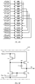
- the display panel is configured as a dual-gate drive display panel. That is, a row of subpixel units is connected with two gate lines correspondingly, and for example, two adjacent subpixel units in the row are connected to different gate lines respectively.
- the first row of subpixel units PU is connected with the gate lines GL ⁇ 1>, GL ⁇ 2>
- the second row of subpixel units PU is connected with the gate lines GL ⁇ 3>, GL ⁇ 4>
- the third row of subpixel units PU is connected with the gate lines GL ⁇ 5>, GL ⁇ 6>
- the fourth row of subpixel units PU is connected with the gate lines GL ⁇ 7>, GL ⁇ 8>
- the fifth row of subpixel units PU is connected with the gate lines GL ⁇ 9>, GL ⁇ 10 >.
- the display panel further includes a plurality of data lines DL (for example, DL ⁇ n-1>, DL ⁇ n>, DL ⁇ n+1>, or the like) for transmitting data signals.
- a plurality of data lines DL for example, DL ⁇ n-1>, DL ⁇ n>, DL ⁇ n+1>, or the like
- the two subpixel units adjacent to each other in a row and connected to different gate lines are connected to the same data line.
- the plurality of data lines DL have zigzag shapes, and the plurality of subpixel units PU connected with any one data line DL receive the data signals having the same polarity.
- a data drive circuit may be adopted to provide the data signal to the subpixel unit PU through the data line DL.
- a 2-point polarity switching data drive mode is adopted in the dual-gate drive display panel. That is, in the same row of subpixel units PU, every two adjacent subpixel units PU receive the data signals with the same polarity, and in the same column of subpixel units PU, every two adjacent subpixel units PU receive the data signals with different polarities.
- the display panel in Fig. 1 may be driven by a gate drive circuit
- Fig. 2A shows a part of shift register units (first shift register unit SR1 to sixteenth shift register unit SR 16) included in the gate drive circuit and clock signals (first clock signal CLK1 to sixteenth clock signal CLK16) for the gate drive circuit, and these clock signals are provided by a timing controller (not shown) through corresponding clock signal lines, for example.
- the first shift register unit SR1 receives the first clock signal CLK1
- the second shift register unit SR2 receives the second clock signal CLK2
- the sixteenth shift register unit SR16 receives the sixteenth clock signal CLK16.
- the ninth shift register unit SR9 is cascaded with the first shift register unit SRI
- the tenth shift register unit SR10 is cascaded with the second shift register unit SR2
- the sixteenth shift register unit SR16 is cascaded with the eighth shift register unit SR8.
- the cascading of the shift register units A, B indicates that an output signal of the shift register unit A is supplied to the shift register B as an input signal to trigger the shift register unit B, or an output signal of the shift register unit B is supplied to the shift register unit A as an input signal to trigger the shift register unit A.
- an output signal of the shift register unit A is supplied to the shift register B as an input signal to trigger the shift register unit B, or an output signal of the shift register unit B is supplied to the shift register unit A as an input signal to trigger the shift register unit A.
- Fig. 2B is a circuit diagram of an exemplary shift register unit 600 serving as the nth stage of a gate drive circuit, for example.
- the shift register unit 600 includes a first transistor T1, a second transistor T2, a third transistor T3, a fourth transistor T4 and a storage capacitor C1.
- the first transistor T1 in the shift register unit 600 serves as an output transistor of a signal output end of the shift register unit 600.
- a first electrode of the first transistor T1 is connected with the clock signal CLK
- a second electrode of the first transistor T1 is connected with a first electrode of the second transistor T2, so as to obtain an output end of the shift register unit 600 and output a scanning signal Gn and an input signal for the next-stage shift register unit 600.
- Agate electrode of the first transistor T1 is connected with a pull-up node PU and thus connected with a first electrode of the third transistor T3 and a second electrode of the fourth transistor T4.
- a second electrode of the second transistor T2 is connected with a second electrode of the third transistor T3 and a low level signal VGL.
- Agate electrode of the second transistor T2 is connected with a gate electrode of the third transistor T3 and an output end of the shift register unit 600 of the next row, i.e., the (n+1)th row, so as to receive the scanning signal G(n+1) as an output pull-down control signal.
- the first electrode of the second transistor T2 is connected with the second electrode of the first transistor T1, and may thus be turned on under the control of the output pull-down control signal, and the output signal of the output end is pulled down to the low level signal VGL without outputting the scanning signal Gn.
- the first electrode of the third transistor T3 is also connected with the pull-up node PU and thus electrically connected with the second electrode of the fourth transistor T4 and the gate electrode of the first transistor T1.
- the second electrode of the third transistor T3 is connected to the low level signal VGL.
- the gate electrode of the third transistor T3 is also connected with the output end of the shift register unit 600 in the next row, i.e., the (n+1)th row, so as to receive the scanning signal G(n+1) as a reset control signal (which also serves as the output pull-down control signal), so that the third transistor T3 may be turned on under the control of the reset control signal to reset the pull-up node PU to the low level signal VGL, thereby turning off the first transistor T1.
- a first electrode of the fourth transistor T4 is connected with a gate electrode of the fourth transistor T4 and the output end of the shift register unit 600 of the previous row, i.e., the (n-1)th row, so as to receive the scanning signal G(n-1) as the input signal (and also as an input control signal), and the second electrode of the fourth transistor T4 is connected with the pull-up node PU, so that the pull-up node PU may be charged when the fourth transistor T4 is turned on, so as to turn on the first transistor T1 by a voltage of the pull-up node PU, thereby outputting the clock signal CLK through the output end.
- the storage capacitor C1 has an end connected with the gate electrode of the first transistor T1, i.e., the pull-up node PU, and the other end connected with the second electrode of the first transistor T1, thereby storing a level of the pull-up node PU, and continuously pulling up, when the first transistor T1 is turned on for output signals, the level of the pull-up node PU due to a bootstrap effect of the first transistor T1 to improve an output performance.
- the scanning signal G(n-1) is at a high level
- the fourth transistor T4 is turned on and charges the pull-up node PU
- the first transistor T1 is turned on due to the increased level of the pull-up node PU, so that the clock signal CLK may be output by the output end through the first transistor T1. That is, the scanning signal Gn is equal to the clock signal CLK.
- the scanning signal Gn also outputs the high level.
- the high level signal Gn is inputted into gate line GL of the corresponding row by the shift register unit 600 of the gate drive circuit, so that the signal is applied to the gate electrodes of the thin film transistors in all the subpixel units corresponding to the gate line GL of the row to turn on all the thin film transistors, and the data signal is input to a liquid crystal capacitor of the corresponding subpixel unit through the thin film transistor in each subpixel unit, so as to charge the liquid crystal capacitor in the corresponding subpixel unit, thereby writing a signal voltage to the subpixel unit and maintaining the signal voltage.
- a progressive scan driving function may be achieved by the gate drive circuit, for example.
- the shift register unit of the gate drive circuit has a structure not limited to the above-described structure, may have any applicable structure, and may also include more or fewer transistors and/or capacitors.
- subcircuits for achieving functions of pull-up node control, pull-down node control, noise reduction, or the like are added, which is not limited in the embodiments of the present disclosure.
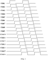
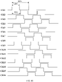
- Fig. 3 shows a timing relationship of the clock signals (the first clock signal CLK1 to the sixteenth clock signal CLK16) in Fig. 2A .
- the first to sixteenth clock signals CLK1-CLK16 have equal duty ratios (i.e., ratios of duration of the high level to periods) and equal periods.
- the time when the sixteen clock signals are at the high level covers an entire time range, and thus, the sixteen sub-clock signals may just form a cyclic group.
- the time length by any two adjacent clock signals are staggered in timing may be defined as a time unit TU, and thus, the period of the clock signal is 16 ⁇ TU.
- the time unit TU Based on the definition of the time unit TU, two clock signals being adjacent in timing indicates that the two clock signals are staggered by one time unit TU in timing.
- the following embodiments have the same description on the time unit TU and the timing adjacency as the above description, and are not repeated.
- the display panel is required to be detected after the manufacturing process is completed.
- the whole display panel is made to display the same color, for example, red, green, blue, or the like.
- the order for the subpixel units PU connected with the data line DL ⁇ n-1> is R->B->R->G->R->B->R->G->R->B->R->G->R->B->R->G->R->B->R->G.
- the data signal required to be provided by the data line DL ⁇ n-1> has a polarity order of +-+-+-+-+-+-+-+-+- (the red subpixel unit R required to be turned on corresponds to the polarity +, and the subpixel unit of other colors corresponds to the polarity -), and the polarity of the provided data signal is reversed 16 times (a change of the polarity from + to - or from - to + is called a polarity reversal);
- the order for the subpixel units PU connected with the data line DL ⁇ n> is R->G->B->G->R->G->B->G->R->G->B->G->R->G->B->G.
- the data signal required to be provided by the data line DL ⁇ n> has a polarity order of +---+---+---+--- (the red subpixel unit R required to be turned on corresponds to the polarity +, and the subpixel unit of other colors corresponds to the polarity -), and the polarity of the provided data signal is reversed 8 times; as another example, the order for the subpixel units PU connected with the data line DL ⁇ n+1> is B->G->R->B->B->G->R->B->B->G->R->B->B->G->R->B->B->G->R->B.
- the data signal required to be provided by the data line DL ⁇ n+1> has a polarity order of --+---+---+---+- (the red subpixel unit R required to be turned on corresponds to the polarity +, and the subpixel unit of other colors corresponds to the polarity -), and the polarity of the provided data signal is reversed 8 times.
- the required number of switching is more when the data drive circuit provides the data signal, which increases power consumption of the display panel.
- the inventor conceives that the subpixel units of the same color connected with the same data line DL may display successively in timing, so that the above-mentioned number of the polarity reversals may be reduced, thereby reducing the power consumption of the display panel.
- every four adjacent subpixel units PU connected with the same data line DL are arranged as a group.
- the subpixel units PU connected with the data line DL ⁇ n-1> may be turned on in an order of R->R->R->R->R->R->R->R->B->B->B->B->G->G->G->G->G, and in this case, the polarity is reversed 2 times when the data signal is provided by the data drive circuit.
- the subpixel units PU connected with the data line DL ⁇ n> may be turned on in an order of B->B->B->B->R->R->R->G->G->G->G->G->B->B->B, and in this case, the polarity is reversed 3 times when the data signal is provided by the data drive circuit.
- the subpixel units PU connected with the data line DL ⁇ n+1> may be turned on in an order of R->R->R->R->B->B->B->B->G->G->G->G->G->G->G->G->G->G->G->G->G->G->G->G->G->G->G->G->G->G->G->G->G->G->G->G->G->G->G->G->G->G->G->G->G->G->G->G->G->G->G->G->G->G->G->G->G->G->G->G->G->G->G->G->G->G->G->G->G->G->G->G->G->G
- the shift register units (SR) and the gate lines (GL) adopt a staggered connection relationship, which increases a design difficulty, thereby causing problems of a poor quality, a low product yield, or the like.
- At least one embodiment of the present disclosure provides a display panel including a display region and a peripheral region.
- the display region includes a subpixel unit array having a plurality of rows and a plurality of columns of subpixel units, a gate drive circuit is provided in the peripheral region, the display region further includes a plurality of gate lines and a plurality of data lines for driving the subpixel unit array, each subpixel unit is driven to work by a scanning signal provided by one gate line and a data signal provided by one data line, and the same data line is connected with at least two subpixel units which are not adjacent to each other and have the same color;
- the gate drive circuit includes a plurality of shift register units which are arranged sequentially, and the plurality of gate lines are arranged sequentially and electrically connected in one-to-one correspondence with the plurality of shift register units which are arranged sequentially;
- the gate drive circuit is configured to receive a clock signal and generate the scanning signal, so as to enable the at least two subpixel units of the same color which are connected with the same data line
- At least one embodiment of the present disclosure further provides a display device and a driving method which correspond to the above-mentioned display panel.
- the problems of the poor quality and the low product yield caused by staggered wiring of the gate drive circuit and the gate line in the past may be avoided, and meanwhile, the power consumption may be reduced.
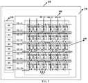
- At least one embodiment of the present disclosure provides a display panel 10 including a display region DR and a peripheral region PR, as shown in Fig. 5 .
- the display region DR includes a subpixel unit array 100 having a plurality of rows and a plurality of columns of subpixel units PU. It should be noted that only 5 rows and 12 columns of subpixel units PU are shown in Fig. 5 schematically, the embodiments of the present disclosure include but are not limited to this scenario, and the number of the subpixel units PU included by the display panel 10 may be set as required. For example, the subpixel unit array 100 shown in Fig. 5 may be arranged as in Fig. 1 .
- a gate drive circuit 200 is provided in the peripheral region PR, the display region DR further includes a plurality of gate lines GL (for example, GL ⁇ 1>, GL ⁇ 2>, or the like) and a plurality of data lines DL (for example, DL ⁇ 1>, DL ⁇ 2>, DL ⁇ 3>, or the like) for driving the subpixel unit array 100, each subpixel unit PU is driven to display by a scanning signal provided by one gate line GL and a data signal provided by one data line DL, and the same data line DL is connected with at least two subpixel units PU which are not adjacent to each other and have the same color.
- GL for example, GL ⁇ 1>, GL ⁇ 2>, or the like
- data lines DL for example, DL ⁇ 1>, DL ⁇ 2>, DL ⁇ 3>, or the like
- the subpixel units PU connected with the data line DL ⁇ 1> has an order (which is from top to bottom and from right to left in the drawing, and the same applies below) of R->B->R->G->R->B->R->G->R->B->R->G->R->B->R->G
- the subpixel units PU connected with the data line DL ⁇ 2> has an order of R->G->B->G->R->G->B->G->R->G->B->G->R->G->B->G->G->B->G
- the subpixel units PU connected with the data line DL ⁇ 3> has an order of B->G->R->B->B->G->R->B->B->G->R->B->B->G->R->B.
- the subpixel units PU of the same color are not adjacent among the plurality of subpixel units PU connected with each data line DL, and the embodiments of the present disclosure include but are not limited this scenario.
- the subpixel units PU of one color are not adjacent, and the subpixel units PU of the other two colors are adjacent; as another example, it is also possible that only the subpixel units PU of two colors are not adjacent, and the subpixel units PU of another color are adjacent.
- the gate drive circuit 200 includes a plurality of shift register units S1 to S10 arranged in sequence, and the plurality of gate lines GL are arranged in sequence and electrically connected with the plurality of shift register units (S1 to S10, or the like) arranged in sequence in a one-to-one correspondence in order.
- staggered wiring is avoided when the plurality of shift register units in the gate drive circuit 200 of the display panel 10 are connected with the plurality of gate lines GL, thereby avoiding the problems of the poor quality and the low product yield caused by the staggered wiring of the gate drive circuit 200 and the gate line GL in the past. It should be noted that only 10 shift register units in the gate drive circuit 200 are shown in Fig.
- the embodiments of the present disclosure include but are not limited to this scenario, and the number of the shift register units included in the gate drive circuit 200 may be set as required.
- the number of the shift register units may be set to be twice the number of the rows of the subpixel units PU.
- the gate drive circuit 200 is configured to receive a clock signal and generate the scanning signal, so as to enable at least two subpixel units PU of the same color which are connected with the same data line DL and not adjacent to each other to display successively in timing.
- the subpixel units PU connected with the data line DL ⁇ 1> may have a display order of R->R->R->R->R->R->R->B->B->B->G->G->G->G->G
- the subpixel units PU connected with the data line DL ⁇ 2> may have a display order of B->B->B->B->R->R->R->R->G->G->G->G->G->G->B->B->B->B->B
- the subpixel units PU connected with the data line DL ⁇ 2> may have a display order of R->R->R->R->B->B->B->G->G->G->G->G->G->G->G->G->G->G->G->G->G->G->G->G->G->G->G->G
- the subpixel unit array 100 in the display region DR is driven by the gate drive circuit 200, so as to enable the at least two subpixel units PU of the same color which are connected with the same data line DL and not adj acent to each other to display successively in timing, for example, enable all the subpixel units PU of the same color which are connected with the same data line DL and not adjacent to each other to display successively in timing.
- the number of the polarity reversals of the data signal supplied to the subpixel unit array 100 may be reduced, thereby reducing the power consumption of the display panel 10.
- the data signal may be supplied to the subpixel unit array 100 by a data drive circuit.
- the plurality of subpixel units PU connected with the same data line DL sequentially at least have a first color and a second color
- the subpixel units PU of the first color have a minimum arrangement period of G1
- the subpixel units PU of the second color have a minimum arrangement period of G2
- G is a least common multiple of G1 and G2.
- the blue subpixel units PU also have an arrangement period of 4, the description is made here by taking the two colors as an example, but when the arrangement periods of the three colors are different from each other, the value of G is the least common multiple of the arrangement periods of the subpixel units PU of the three colors.
- the subpixel units PU which are driven sequentially have order numbers of 2, 6, 10 and 14; in the 3rd driving group, the subpixel units PU which are driven sequentially
- the gate drive circuit 200 is configured to enable the driving groups to be driven in an order of the 1st driving group, the 3rd driving group, the 2nd driving group and the 4th driving group. That is, the 16 subpixel units PU connected with the same data line are driven in an order of 1, 5, 9, 13, 3, 7, 11, 15, 2, 6, 10, 14, 4, 8, 12 and 16.
- the gate drive circuit 200 shown in Fig. 5 is further described below.
- the plurality of shift register units PU are divided into at least one shift-register-unit scanning group 210, each of which includes a plurality of shift register unit groups 220 formed by adjacent and cascaded shift register units PU, and every two adjacent shift register unit groups 220 are not cascaded.
- each shift register unit group 220 includes m adjacent and cascaded shift register units PU, and m is an integer greater than or equal to 2.
- each shift-register-unit scanning group 210 includes 16 shift register units (S ⁇ 1> to S ⁇ 16>), and in each shift-register-unit scanning group 210, the (k+1)th and (k)th shift register units are cascaded to form one shift register unit group 220, the (k+1)th and (k+2)th shift register units are not cascaded, and k is 1, 3, 5, 7, 9, 11, 13 or 15.
- the 2nd and 1st shift register units S ⁇ 2>, S ⁇ 1> are cascaded to form one shift register unit group 220, and the 2nd and 3rd shift register units S ⁇ 2>, S ⁇ 3> are not cascaded;
- the 4th and 3rd shift register units S ⁇ 4>, S ⁇ 3> are cascaded to form one shift register unit group 220, and the 4th and 5th shift register units S ⁇ 4>, S ⁇ 5> are not cascaded;
- the 6th and 5th shift register units S ⁇ 6>, S ⁇ 5> are cascaded to form one shift register unit group 220, and the 6th and 7th shift register units S ⁇ 6>, S ⁇ 7> are not cascaded;
- the 8th and 7th shift register units S ⁇ 8>, S ⁇ 7> are cascaded to form one shift register unit group 220, and the 8th and 9th shift register units S ⁇ 8>, S ⁇ 9> are not cascaded;
- the 10th and 9th shift register units S ⁇ 10 are cascade
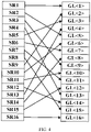
- the gate drive circuit 200 includes a plurality of cascaded shift-register-unit scanning groups 210 is described below in conjunction with Fig. 8 .
- the gate drive circuit 200 includes a plurality of shift-register-unit scanning groups 210.
- Fig. 8 only shows two shift-register-unit scanning groups 210 included in the gate drive circuit 200, which are denoted as 210 ⁇ 1> and 210 ⁇ 2> respectively, for example.
- the kth shift register unit in a shift-register-unit scanning group 210 ⁇ 2> of the two adjacent shift-register-unit scanning groups 210 is connected with the (k+1)th shift register unit in the other shift-register-unit scanning group 210 ⁇ 1> of the two adjacent shift-register-unit scanning groups 210, and k is 1, 3, 5, 7, 9, 11, 13 or 15.
- a relative positional relationship between the two shift-register-unit scanning groups 210 shown in Fig. 8 does not represent a true positional relationship, and for convenience of description here, the shift-register-unit scanning group 210 ⁇ 2> is drawn at the right side of the shift-register-unit scanning group 210 ⁇ 1>.
- the 1st shift register unit S ⁇ 1> in the shift-register-unit scanning group 210 ⁇ 2> is connected with the 2nd shift register unit S ⁇ 2> in the shift-register-unit scanning group 210 ⁇ 1>;
- the 3rd shift register unit S ⁇ 3> in the shift-register-unit scanning group 210 ⁇ 2> is connected with the 4th shift register unit S ⁇ 4> in the shift-register-unit scanning group 210 ⁇ 1>;
- the 5th shift register unit S ⁇ 5> in the shift-register-unit scanning group 210 ⁇ 2> is connected with the 6th shift register unit S ⁇ 6> in the shift-register-unit scanning group 210 ⁇ 1>;
- the 7th shift register unit S ⁇ 7> in the shift-register-unit scanning group 210 ⁇ 2> is connected with the 8th shift register unit S ⁇ 8> in the shift-register-unit scanning group 210 ⁇ 1>;
- the 9th shift register unit S ⁇ 9> in the shift-register-unit scanning group 210 ⁇ 2> is connected with the 10th shift register unit
- the first clock signal CK1 to the sixteenth clock signal CK16 are received by the 16 shift register units (S ⁇ 1> to S ⁇ 16>) in each shift-register-unit scanning group 210 respectively, and have equal periods and equal duty ratios.
- Fig. 10 shows a signal timing diagram of the clock signal for the display panel 10 according to the embodiments of the present disclosure.
- the first to sixteenth clock signals CK1 to CK16 are provided by a timing controller, and have equal periods and equal duty ratios.
- each clock signal has a period of 16 time units TU, i.e., 16TU, and a ratio of the time during which the clock signal is at a high level to the period in each clock signal is 7.2/16. That is, each clock signal has a duty ratio of 9/20.
- the duty ratio shown in Fig. 10 is merely illustrative, and the clock signal in the embodiments of the present disclosure may also have other duty ratios.
- the time during which the clock signal is at a low level may be slightly longer than the time during which the clock signal is at the high level.
- the first, fifth, ninth, thirteenth, third, seventh, eleventh and fifteenth clock signals CK1, CK5, CK9, CK13, CK3, CK7, CK11, CK15 are adjacent to each other in timing.
- the second, sixth, tenth, fourteenth, fourth, eighth, twelfth and sixteenth clock signals CK2, CK6, CK10, CK14, CK4, CK8, CK12, CK16 are adjacent to each other in timing.
- the first and second clock signals CK1, CK2 differ in timing by 8 time units TU.
- the first to sixteenth clock signals CK1 to CK16 are supplied to the gate drive circuit 200 in an order of CK1->CK5->CK9->CK13->CK3->CK7->CK11->CK15->CK2->CK6->CK10->CK14->CK4->CK8->CK12->CK16.
- the above-mentioned order of the clock signals may be stored in the timing controller or other devices of the display panel 10 in a form of program codes (algorithm), and the program codes may be executed directly to generate the required clock signal when required.
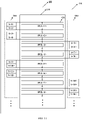
- the subpixel unit array 100 is divided into at least one subpixel-unit scanning group 110 in one-to-one correspondence to the at least one shift-register-unit scanning group 210.
- Fig. 11 shows two subpixel-unit scanning groups 110 and two corresponding shift-register-unit scanning groups 210, the embodiments of the present disclosure include but are not limited to this scenario, and the number of the subpixel-unit scanning groups 110 in the embodiments of the present disclosure may be set as required.
- each shift-register-unit scanning group 110 includes 16 shift register units (S ⁇ 1> to S ⁇ 16>), and each subpixel-unit scanning group 110 includes 8 rows of subpixel units adjacent to each other, for example, a first row of subpixel units PUL ⁇ 1> to an eighth row of subpixel units PUL ⁇ 8>.
- the qth row of subpixel units in each subpixel-unit scanning group 110 is electrically connected with the (2q-1)th shift register unit and the 2qth shift register unit in the shift-register-unit scanning group 210 corresponding to the subpixel-unit scanning group 110, and q is an integer greater than or equal to 1 and less than or equal to 8. For example, as shown in Fig.
- the first row of subpixel units PUL ⁇ 1> is electrically connected with the first and second shift register units S ⁇ 1>, S ⁇ 2>;
- the second row of subpixel units PUL ⁇ 2> is electrically connected with the third and fourth shift register units S ⁇ 3>, S ⁇ 4>;
- the third row of subpixel units PUL ⁇ 3> is electrically connected with the fifth and sixth shift register units S ⁇ 5>, S ⁇ 6>;
- the fourth row of subpixel units PUL ⁇ 4> is electrically connected with the seventh and eighth shift register units S ⁇ 7>, S ⁇ 8>;
- the fifth row of subpixel units PUL ⁇ 5> is electrically connected with the ninth and tenth shift register units S ⁇ 9>, S ⁇ 10>;
- the sixth row of subpixel units PUL ⁇ 6> is electrically connected with the eleventh and twelfth shift register units S ⁇ 11>, S ⁇ 12>;
- the seventh row of subpixel units PUL ⁇ 7> is electrically connected with the thirteenth and fourteenth shift register units S ⁇ 13>,
- the shift register unit may be electrically connected with the corresponding row of subpixel units by the gate line.
- the gate line For example, as shown in Fig. 12 , one gate line GL is provided at each of two sides of each row of subpixel units, and the row of subpixel units is connected with the two gate lines GL provided at the two sides.
- Fig. 13 shows a way of connection among the gate line GL, the shift register unit and the corresponding subpixel unit.
- the display panel 10 includes the gate drive circuit 200 provided in the peripheral region PR, and further includes the data drive circuit 300 provided in the peripheral region PR.
- the gate drive circuit 200 is connected with the plurality of gate lines, and is also connected with the timing controller 400 through a clock signal line to receive the clock signal;
- the data drive circuit 300 is connected with the plurality of data lines DL, and configured to supply the data signal to the subpixel unit array 100 by means of a 2-point polarity switching manner.
- the 2-point polarity switching manner may refer to corresponding description in Fig. 1 , and is not repeated here.
- any one of the plurality of data lines DL provides the data signal having the same polarity, and has a zigzag wiring shape.
- a working principle of the display panel 10 shown in Fig. 13 will be described below in conjunction with the signal timing diagram shown in Fig. 10 .
- the following description will be given by taking the subpixel unit PU connected with the data line DL ⁇ 1> as an example.
- the first shift register unit S ⁇ 1> provides a scanning signal through the gate line GL ⁇ 1>, and meanwhile, the data drive circuit 300 provides a data signal through the data line DL ⁇ 1>, so that one red subpixel unit R connected with the data line DL ⁇ 1> is driven by the scanning signal and the data signal to display.
- the fifth shift register unit S ⁇ 5> provides a scanning signal through the gate line GL ⁇ 5>, and meanwhile, the data drive circuit 300 provides a data signal through the data line DL ⁇ 1>, so that another red subpixel unit R connected with the data line DL ⁇ 1> is driven by the scanning signal and the data signal to display.
- the ninth shift register unit S ⁇ 9> provides a scanning signal through the gate line GL ⁇ 9>, and meanwhile, the data drive circuit 300 provides a data signal through the data line DL ⁇ 1>, so that another red subpixel unit R connected with the data line DL ⁇ 1> is driven by the scanning signal and the data signal to display.
- the thirteenth shift register unit S ⁇ 13> provides a scanning signal through the gate line GL ⁇ 13> (S ⁇ 13> and the gate line GL ⁇ 13> are not shown in Fig. 13 ), and meanwhile, the data drive circuit 300 provides a data signal through the data line DL ⁇ 1>, so that another red subpixel unit R connected with the data line DL ⁇ 1> is driven by the scanning signal and the data signal to display.
- the gate drive circuit 200 supplies the scanning signal to the subpixel unit array 100 according to the timing of the received clock signals
- the data drive circuit 300 supplies the data signal to the turned-on subpixel units PU through the data line DL ⁇ 1>, so that the subpixel units PU connected with the data line DL ⁇ 1> displays in an order of R->R->R->R->R->R->R->R->B->B->B->G->G->G->G->G, so as to enable the subpixel units PU of the same color among the plurality of subpixel units PU connected with the data line DL ⁇ 1> to display successively in timing, thereby decreasing the number of the polarity reversals of the data signal supplied to the subpixel unit array 100, and reducing the power consumption of the display panel 10.
- the Lth shift register unit is provided at a first side of the display region DR
- the Rth shift register unit is provided at a second side of the display region DR opposite to the first side
- L is 1, 2, 3, 4, 9, 10, 11 or 12
- R is 5, 6, 7, 8, 13, 14, 15 or 16.
- the first side is the left side of the display region DR
- the second side is the right side of the display region DR
- the first side is the right side of the display region DR
- the second side is the left side of the display region DR.
- the shift register units in the gate drive circuit 200 in the display panel 10 may be provided at both sides of the display region DR respectively.
- all the shift register units in the gate drive circuit 200 may be provided at one side of the display region DR.
- a bezel of the display panel may have a size which is reduced, and a narrow bezel may be implemented more easily.
- At least one embodiment of the present disclosure further provides a display device 1 including any one of the display panels 10 according to the embodiments of the present disclosure, as shown in Fig. 15 .
- the display device 1 may be configured as any product or component with a displaying function, such as a liquid crystal display panel, a liquid crystal display television, a display, an OLED panel, an OLED television, an electronic paper, a mobile phone, a tablet computer, a notebook computer, a digital photo frame, a navigator, or the like.
- a displaying function such as a liquid crystal display panel, a liquid crystal display television, a display, an OLED panel, an OLED television, an electronic paper, a mobile phone, a tablet computer, a notebook computer, a digital photo frame, a navigator, or the like.
- At least one embodiment of the present disclosure further provides a driving method of a display panel, for example, any one of the display panels 10 according to the embodiments of the present disclosure.
- the driving method includes: supplying the clock signal to the gate drive circuit 200 to cause the gate drive circuit 200 to generate the scanning signal, so as to enable at least two subpixel units PU of the same color which are connected with the same data line DL and not adjacent to each other to display successively in timing.
- the plurality of subpixel units PU connected with the same data line DL sequentially at least have a first color and a second color
- the subpixel units PU of the first color have a minimum arrangement period of G1
- the subpixel units PU of the second color have a minimum arrangement period of G2
- the driving method further includes: taking a least common multiple of G1 and G2 as G.
- the driving method further includes: driving the 16 subpixel units connected with the same data line sequentially according to a sequence of following order numbers: 1, 5, 9, 13, 3, 7, 11, 15, 2, 6, 10, 14, 4, 8, 12 and 16.
- At least one embodiment of the present disclosure further provides a driving method of a display panel.
- a subpixel unit array 100 of the display panel 10 is divided into at least one subpixel-unit scanning group 110 in one-to-one correspondence with at least one shift-register-unit scanning group 210, and each subpixel-unit scanning group 110 includes 8 rows of subpixel units PU adjacent to each other.
- the driving method includes the following operation steps:
Landscapes
- Engineering & Computer Science (AREA)
- Physics & Mathematics (AREA)
- Computer Hardware Design (AREA)
- General Physics & Mathematics (AREA)
- Theoretical Computer Science (AREA)
- Chemical & Material Sciences (AREA)
- Crystallography & Structural Chemistry (AREA)
- Control Of Indicators Other Than Cathode Ray Tubes (AREA)
- Liquid Crystal Display Device Control (AREA)
Applications Claiming Priority (1)
| Application Number | Priority Date | Filing Date | Title |
|---|---|---|---|
| PCT/CN2019/098700 WO2021016942A1 (zh) | 2019-07-31 | 2019-07-31 | 显示面板、显示装置以及驱动方法 |
Publications (2)
| Publication Number | Publication Date |
|---|---|
| EP4006892A1 true EP4006892A1 (de) | 2022-06-01 |
| EP4006892A4 EP4006892A4 (de) | 2022-12-21 |
Family
ID=74228516
Family Applications (1)
| Application Number | Title | Priority Date | Filing Date |
|---|---|---|---|
| EP19933196.8A Pending EP4006892A4 (de) | 2019-07-31 | 2019-07-31 | Anzeigetafel, anzeigevorrichtung und ansteuerverfahren |
Country Status (4)
| Country | Link |
|---|---|
| US (4) | US11715401B2 (de) |
| EP (1) | EP4006892A4 (de) |
| CN (2) | CN112673417B (de) |
| WO (1) | WO2021016942A1 (de) |
Families Citing this family (15)
| Publication number | Priority date | Publication date | Assignee | Title |
|---|---|---|---|---|
| US11818330B2 (en) * | 2019-11-29 | 2023-11-14 | Boe Technology Group Co., Ltd. | Display device and driving method thereof |
| CN115206244B (zh) * | 2021-04-09 | 2023-11-17 | 京东方科技集团股份有限公司 | 显示面板及其驱动方法、显示装置 |
| CN113257130B (zh) * | 2021-05-17 | 2022-07-12 | 武汉华星光电技术有限公司 | 一种显示区集成栅极驱动电路的显示面板 |
| CN113470559B (zh) * | 2021-06-29 | 2024-03-19 | 厦门天马微电子有限公司 | 驱动电路、驱动方法、显示面板及装置 |
| WO2023092506A1 (zh) * | 2021-11-26 | 2023-06-01 | 京东方科技集团股份有限公司 | 像素阵列驱动方法、装置和显示面板 |
| CN115731845B (zh) * | 2022-11-29 | 2025-02-18 | 京东方科技集团股份有限公司 | 一种显示面板 |
| CN116027593B (zh) * | 2022-12-29 | 2026-03-20 | 长沙惠科光电有限公司 | 显示面板、显示面板的驱动方法以及显示装置 |
| CN116434716A (zh) * | 2023-04-27 | 2023-07-14 | 惠科股份有限公司 | 显示面板的驱动电路、阵列基板及显示面板 |
| CN119229760B (zh) * | 2023-06-29 | 2025-09-19 | 北京京东方显示技术有限公司 | 一种阵列基板、显示装置及驱动方法 |
| CN116978310A (zh) * | 2023-08-01 | 2023-10-31 | 合肥京东方光电科技有限公司 | 显示面板、显示装置及其驱动方法 |
| CN117059046B (zh) * | 2023-09-12 | 2026-03-10 | 厦门天马显示科技有限公司 | 像素电路的控制方法、显示面板和电路驱动装置 |
| WO2025129647A1 (zh) * | 2023-12-22 | 2025-06-26 | 京东方科技集团股份有限公司 | 显示装置的驱动方法、显示装置及电子设备 |
| CN120858403A (zh) * | 2024-02-27 | 2025-10-28 | 京东方科技集团股份有限公司 | 阵列基板、其驱动方法、显示面板及显示装置 |
| CN118173063B (zh) * | 2024-03-21 | 2026-02-13 | 惠科股份有限公司 | 显示面板的驱动电路、显示面板及显示装置 |
| CN118314849A (zh) * | 2024-05-17 | 2024-07-09 | 信利(仁寿)高端显示科技有限公司 | 一种液晶显示面板驱动电路及方法 |
Family Cites Families (29)
| Publication number | Priority date | Publication date | Assignee | Title |
|---|---|---|---|---|
| JP2004264476A (ja) | 2003-02-28 | 2004-09-24 | Sharp Corp | 表示装置およびその駆動方法 |
| CN101377956B (zh) * | 2007-08-31 | 2010-12-29 | 群康科技(深圳)有限公司 | 移位寄存器及液晶显示器 |
| JP5774911B2 (ja) * | 2011-06-01 | 2015-09-09 | 株式会社ジャパンディスプレイ | 表示装置 |
| KR101906182B1 (ko) * | 2011-12-08 | 2018-10-11 | 삼성디스플레이 주식회사 | 표시장치 |
| CN103514846A (zh) | 2012-06-29 | 2014-01-15 | 北京京东方光电科技有限公司 | 一种液晶显示器及其驱动方法 |
| TWI600022B (zh) * | 2012-07-20 | 2017-09-21 | 半導體能源研究所股份有限公司 | 脈衝輸出電路、顯示裝置、及電子裝置 |
| CN103474044B (zh) * | 2013-09-29 | 2016-01-27 | 北京京东方光电科技有限公司 | 一种栅极驱动电路、阵列基板、显示装置以及驱动方法 |
| KR102114155B1 (ko) * | 2013-10-01 | 2020-05-25 | 삼성디스플레이 주식회사 | 표시 장치 및 그 구동 방법 |
| TWI502577B (zh) | 2013-10-18 | 2015-10-01 | Au Optronics Corp | 電荷分享控制方法及顯示面板 |
| KR102202128B1 (ko) * | 2014-01-08 | 2021-01-14 | 삼성디스플레이 주식회사 | 액정표시장치와 그 구동방법 |
| TWI537928B (zh) * | 2014-01-27 | 2016-06-11 | 友達光電股份有限公司 | 顯示面板及其驅動方法 |
| CN103943055B (zh) * | 2014-03-27 | 2016-05-11 | 京东方科技集团股份有限公司 | 一种栅极驱动电路及其驱动方法、显示装置 |
| CN104200786A (zh) * | 2014-07-31 | 2014-12-10 | 京东方科技集团股份有限公司 | 一种阵列基板及其驱动方法、显示面板、显示装置 |
| KR102279353B1 (ko) * | 2014-12-01 | 2021-07-20 | 엘지디스플레이 주식회사 | 표시패널 |
| CN104992957B (zh) | 2015-05-22 | 2018-06-15 | 京东方科技集团股份有限公司 | 阵列基板、显示面板和显示装置 |
| CN106297624B (zh) * | 2015-06-11 | 2020-03-17 | 南京瀚宇彩欣科技有限责任公司 | 移位寄存器和显示装置 |
| CN105182638A (zh) * | 2015-08-28 | 2015-12-23 | 重庆京东方光电科技有限公司 | 阵列基板、显示装置及其驱动方法 |
| CN105244005B (zh) * | 2015-11-24 | 2018-01-09 | 厦门天马微电子有限公司 | 阵列基板、触控显示装置及其驱动方法 |
| CN105629606A (zh) * | 2016-01-13 | 2016-06-01 | 深圳市华星光电技术有限公司 | 液晶显示面板及其驱动方法 |
| CN105845066A (zh) | 2016-05-30 | 2016-08-10 | 深圳市华星光电技术有限公司 | 显示面板的驱动方法 |
| JP2018072821A (ja) * | 2016-10-26 | 2018-05-10 | 株式会社半導体エネルギー研究所 | 表示装置およびその動作方法 |
| KR102643465B1 (ko) | 2017-01-17 | 2024-03-05 | 삼성디스플레이 주식회사 | 표시 장치 및 그 구동 방법 |
| CN106875890B (zh) * | 2017-04-27 | 2021-01-12 | 京东方科技集团股份有限公司 | 阵列基板、显示面板、显示设备及驱动方法 |
| CN107346650A (zh) * | 2017-09-14 | 2017-11-14 | 厦门天马微电子有限公司 | 显示面板、显示装置和扫描驱动方法 |
| CN108375855B (zh) * | 2018-02-28 | 2021-03-12 | 厦门天马微电子有限公司 | 显示面板和显示装置 |
| CN108877621B (zh) * | 2018-06-29 | 2022-02-25 | 厦门天马微电子有限公司 | 一种显示面板和显示装置 |
| CN109935212A (zh) * | 2019-02-28 | 2019-06-25 | 合肥京东方卓印科技有限公司 | 显示面板、显示装置及驱动方法 |
| CN109817150A (zh) * | 2019-03-28 | 2019-05-28 | 京东方科技集团股份有限公司 | 一种像素驱动方法、像素驱动装置及显示装置 |
| CN110379390B (zh) | 2019-07-01 | 2022-01-04 | 武汉天马微电子有限公司 | 一种显示面板、其驱动方法及显示装置 |
-
2019
- 2019-07-31 CN CN201980001200.XA patent/CN112673417B/zh active Active
- 2019-07-31 CN CN202211093675.6A patent/CN115938322B/zh active Active
- 2019-07-31 EP EP19933196.8A patent/EP4006892A4/de active Pending
- 2019-07-31 US US16/957,575 patent/US11715401B2/en active Active
- 2019-07-31 WO PCT/CN2019/098700 patent/WO2021016942A1/zh not_active Ceased
-
2023
- 2023-04-20 US US18/137,010 patent/US11948489B2/en active Active
-
2024
- 2024-02-28 US US18/590,339 patent/US12230180B2/en active Active
-
2025
- 2025-01-08 US US19/013,269 patent/US20250148950A1/en active Pending
Also Published As
| Publication number | Publication date |
|---|---|
| US20220383787A1 (en) | 2022-12-01 |
| CN112673417B (zh) | 2022-11-18 |
| US20250148950A1 (en) | 2025-05-08 |
| WO2021016942A1 (zh) | 2021-02-04 |
| EP4006892A4 (de) | 2022-12-21 |
| CN115938322A (zh) | 2023-04-07 |
| US12230180B2 (en) | 2025-02-18 |
| CN115938322B (zh) | 2025-04-01 |
| US20230260442A1 (en) | 2023-08-17 |
| US20240212550A1 (en) | 2024-06-27 |
| US11948489B2 (en) | 2024-04-02 |
| US11715401B2 (en) | 2023-08-01 |
| CN112673417A (zh) | 2021-04-16 |
Similar Documents
| Publication | Publication Date | Title |
|---|---|---|
| US12230180B2 (en) | Display panel, display device and driving method | |
| CN111477159B (zh) | 显示基板、显示面板、显示装置和显示驱动方法 | |
| US9626922B2 (en) | GOA circuit, array substrate, display device and driving method | |
| US11227524B2 (en) | Shift register unit and driving method thereof, gate driving circuit and driving method thereof, and display device | |
| CN110415664B (zh) | 移位寄存器及其驱动方法、栅极驱动电路、显示装置 | |
| EP3571691B1 (de) | Schieberegistereinheit, gate-treiber-schaltung und verfahren zur ansteuerung dafür | |
| EP3686876A1 (de) | Schieberegistereinheit, ansteuerungsvorrichtung, anzeigevorrichtung und ansteuerungsverfahren | |
| US6566643B2 (en) | Electro-optical device, method of driving the same, and electronic apparatus using the same | |
| CN110060645A (zh) | 一种移位寄存器及其驱动方法、栅极驱动电路、显示装置 | |
| CN112703553B (zh) | 移位寄存器单元、栅极驱动电路、显示面板、显示装置以及驱动方法 | |
| CN104952406B (zh) | 移位寄存器及其驱动方法、栅极驱动电路和显示装置 | |
| US11144159B2 (en) | Driving method of display panel, display panel and display device | |
| EP3736815A1 (de) | Schieberegistereinheit, gate-ansteuerungsvorrichtung, anzeigevorrichtung und steuerungsverfahren | |
| CN106205461A (zh) | 移位寄存器单元、驱动方法、栅极驱动电路及显示装置 | |
| EP3872801A1 (de) | Schieberegistereinheit, gatetreiberschaltung, anzeigevorrichtung und ansteuerungsverfahren | |
| CN109410810B (zh) | 移位寄存器单元及其驱动方法、栅极驱动电路及显示装置 | |
| US20200098441A1 (en) | Shift register unit and driving method, gate driving circuit, and display device | |
| US20250157433A1 (en) | Display panel, driving method for the display panel and display device | |
| CN100410997C (zh) | 液晶显示装置 | |
| CN106710544B (zh) | 移位寄存器电路、栅极驱动电路及显示装置 | |
| US6621478B1 (en) | Semiconductor device and display module | |
| CN105931607B (zh) | 显示面板的驱动方法及液晶显示装置 | |
| CN117672108A (zh) | 显示面板 | |
| US11804196B2 (en) | Display substrate including shift circuits configured to provide gate driving signals in a skipping mode, method for driving same and display device | |
| CN120375773A (zh) | 驱动电路及显示装置 |
Legal Events
| Date | Code | Title | Description |
|---|---|---|---|
| STAA | Information on the status of an ep patent application or granted ep patent |
Free format text: STATUS: UNKNOWN |
|
| STAA | Information on the status of an ep patent application or granted ep patent |
Free format text: STATUS: THE INTERNATIONAL PUBLICATION HAS BEEN MADE |
|
| PUAI | Public reference made under article 153(3) epc to a published international application that has entered the european phase |
Free format text: ORIGINAL CODE: 0009012 |
|
| STAA | Information on the status of an ep patent application or granted ep patent |
Free format text: STATUS: REQUEST FOR EXAMINATION WAS MADE |
|
| 17P | Request for examination filed |
Effective date: 20211221 |
|
| AK | Designated contracting states |
Kind code of ref document: A1 Designated state(s): AL AT BE BG CH CY CZ DE DK EE ES FI FR GB GR HR HU IE IS IT LI LT LU LV MC MK MT NL NO PL PT RO RS SE SI SK SM TR |
|
| RIC1 | Information provided on ipc code assigned before grant |
Ipc: G09G 3/3266 20160101ALI20220705BHEP Ipc: G09G 3/20 20060101ALI20220705BHEP Ipc: G02F 1/1362 20060101ALI20220705BHEP Ipc: G09G 3/36 20060101AFI20220705BHEP |
|
| DAV | Request for validation of the european patent (deleted) | ||
| DAX | Request for extension of the european patent (deleted) | ||
| A4 | Supplementary search report drawn up and despatched |
Effective date: 20221121 |
|
| RIC1 | Information provided on ipc code assigned before grant |
Ipc: G09G 3/3266 20160101ALI20221115BHEP Ipc: G09G 3/20 20060101ALI20221115BHEP Ipc: G02F 1/1362 20060101ALI20221115BHEP Ipc: G09G 3/36 20060101AFI20221115BHEP |
|
| STAA | Information on the status of an ep patent application or granted ep patent |
Free format text: STATUS: EXAMINATION IS IN PROGRESS |
|
| 17Q | First examination report despatched |
Effective date: 20250212 |