EP4006894A1 - Dispositif, procédé et programme de commande d'affichage d'image - Google Patents
Dispositif, procédé et programme de commande d'affichage d'image Download PDFInfo
- Publication number
- EP4006894A1 EP4006894A1 EP20844303.6A EP20844303A EP4006894A1 EP 4006894 A1 EP4006894 A1 EP 4006894A1 EP 20844303 A EP20844303 A EP 20844303A EP 4006894 A1 EP4006894 A1 EP 4006894A1
- Authority
- EP
- European Patent Office
- Prior art keywords
- display
- user
- video
- auxiliary pattern
- change
- Prior art date
- Legal status (The legal status is an assumption and is not a legal conclusion. Google has not performed a legal analysis and makes no representation as to the accuracy of the status listed.)
- Withdrawn
Links
Images


Classifications
-
- G—PHYSICS
- G06—COMPUTING OR CALCULATING; COUNTING
- G06T—IMAGE DATA PROCESSING OR GENERATION, IN GENERAL
- G06T11/00—Two-dimensional [2D] image generation
- G06T11/10—Texturing; Colouring; Generation of textures or colours
-
- G—PHYSICS
- G02—OPTICS
- G02B—OPTICAL ELEMENTS, SYSTEMS OR APPARATUS
- G02B27/00—Optical systems or apparatus not provided for by any of the groups G02B1/00 - G02B26/00, G02B30/00
- G02B27/02—Viewing or reading apparatus
-
- G—PHYSICS
- G06—COMPUTING OR CALCULATING; COUNTING
- G06F—ELECTRIC DIGITAL DATA PROCESSING
- G06F3/00—Input arrangements for transferring data to be processed into a form capable of being handled by the computer; Output arrangements for transferring data from processing unit to output unit, e.g. interface arrangements
- G06F3/01—Input arrangements or combined input and output arrangements for interaction between user and computer
- G06F3/011—Arrangements for interaction with the human body, e.g. for user immersion in virtual reality
- G06F3/012—Head tracking input arrangements
-
- G—PHYSICS
- G06—COMPUTING OR CALCULATING; COUNTING
- G06F—ELECTRIC DIGITAL DATA PROCESSING
- G06F3/00—Input arrangements for transferring data to be processed into a form capable of being handled by the computer; Output arrangements for transferring data from processing unit to output unit, e.g. interface arrangements
- G06F3/01—Input arrangements or combined input and output arrangements for interaction between user and computer
- G06F3/011—Arrangements for interaction with the human body, e.g. for user immersion in virtual reality
- G06F3/013—Eye tracking input arrangements
-
- G—PHYSICS
- G06—COMPUTING OR CALCULATING; COUNTING
- G06F—ELECTRIC DIGITAL DATA PROCESSING
- G06F3/00—Input arrangements for transferring data to be processed into a form capable of being handled by the computer; Output arrangements for transferring data from processing unit to output unit, e.g. interface arrangements
- G06F3/01—Input arrangements or combined input and output arrangements for interaction between user and computer
- G06F3/048—Interaction techniques based on graphical user interfaces [GUI]
- G06F3/0484—Interaction techniques based on graphical user interfaces [GUI] for the control of specific functions or operations, e.g. selecting or manipulating an object, an image or a displayed text element, setting a parameter value or selecting a range
-
- G—PHYSICS
- G09—EDUCATION; CRYPTOGRAPHY; DISPLAY; ADVERTISING; SEALS
- G09G—ARRANGEMENTS OR CIRCUITS FOR CONTROL OF INDICATING DEVICES USING STATIC MEANS TO PRESENT VARIABLE INFORMATION
- G09G5/00—Control arrangements or circuits for visual indicators common to cathode-ray tube indicators and other visual indicators
- G09G5/02—Control arrangements or circuits for visual indicators common to cathode-ray tube indicators and other visual indicators characterised by the way in which colour is displayed
-
- G—PHYSICS
- G09—EDUCATION; CRYPTOGRAPHY; DISPLAY; ADVERTISING; SEALS
- G09G—ARRANGEMENTS OR CIRCUITS FOR CONTROL OF INDICATING DEVICES USING STATIC MEANS TO PRESENT VARIABLE INFORMATION
- G09G5/00—Control arrangements or circuits for visual indicators common to cathode-ray tube indicators and other visual indicators
- G09G5/36—Control arrangements or circuits for visual indicators common to cathode-ray tube indicators and other visual indicators characterised by the display of a graphic pattern, e.g. using an all-points-addressable [APA] memory
- G09G5/37—Details of the operation on graphic patterns
- G09G5/377—Details of the operation on graphic patterns for mixing or overlaying two or more graphic patterns
-
- G—PHYSICS
- G09—EDUCATION; CRYPTOGRAPHY; DISPLAY; ADVERTISING; SEALS
- G09G—ARRANGEMENTS OR CIRCUITS FOR CONTROL OF INDICATING DEVICES USING STATIC MEANS TO PRESENT VARIABLE INFORMATION
- G09G5/00—Control arrangements or circuits for visual indicators common to cathode-ray tube indicators and other visual indicators
- G09G5/36—Control arrangements or circuits for visual indicators common to cathode-ray tube indicators and other visual indicators characterised by the display of a graphic pattern, e.g. using an all-points-addressable [APA] memory
- G09G5/38—Control arrangements or circuits for visual indicators common to cathode-ray tube indicators and other visual indicators characterised by the display of a graphic pattern, e.g. using an all-points-addressable [APA] memory with means for controlling the display position
-
- H—ELECTRICITY
- H04—ELECTRIC COMMUNICATION TECHNIQUE
- H04N—PICTORIAL COMMUNICATION, e.g. TELEVISION
- H04N5/00—Details of television systems
- H04N5/64—Constructional details of receivers, e.g. cabinets or dust covers
-
- G—PHYSICS
- G09—EDUCATION; CRYPTOGRAPHY; DISPLAY; ADVERTISING; SEALS
- G09G—ARRANGEMENTS OR CIRCUITS FOR CONTROL OF INDICATING DEVICES USING STATIC MEANS TO PRESENT VARIABLE INFORMATION
- G09G2340/00—Aspects of display data processing
- G09G2340/04—Changes in size, position or resolution of an image
- G09G2340/0464—Positioning
-
- G—PHYSICS
- G09—EDUCATION; CRYPTOGRAPHY; DISPLAY; ADVERTISING; SEALS
- G09G—ARRANGEMENTS OR CIRCUITS FOR CONTROL OF INDICATING DEVICES USING STATIC MEANS TO PRESENT VARIABLE INFORMATION
- G09G2340/00—Aspects of display data processing
- G09G2340/10—Mixing of images, i.e. displayed pixel being the result of an operation, e.g. adding, on the corresponding input pixels
-
- G—PHYSICS
- G09—EDUCATION; CRYPTOGRAPHY; DISPLAY; ADVERTISING; SEALS
- G09G—ARRANGEMENTS OR CIRCUITS FOR CONTROL OF INDICATING DEVICES USING STATIC MEANS TO PRESENT VARIABLE INFORMATION
- G09G2340/00—Aspects of display data processing
- G09G2340/12—Overlay of images, i.e. displayed pixel being the result of switching between the corresponding input pixels
-
- G—PHYSICS
- G09—EDUCATION; CRYPTOGRAPHY; DISPLAY; ADVERTISING; SEALS
- G09G—ARRANGEMENTS OR CIRCUITS FOR CONTROL OF INDICATING DEVICES USING STATIC MEANS TO PRESENT VARIABLE INFORMATION
- G09G2354/00—Aspects of interface with display user
-
- G—PHYSICS
- G09—EDUCATION; CRYPTOGRAPHY; DISPLAY; ADVERTISING; SEALS
- G09G—ARRANGEMENTS OR CIRCUITS FOR CONTROL OF INDICATING DEVICES USING STATIC MEANS TO PRESENT VARIABLE INFORMATION
- G09G3/00—Control arrangements or circuits, of interest only in connection with visual indicators other than cathode-ray tubes
- G09G3/001—Control arrangements or circuits, of interest only in connection with visual indicators other than cathode-ray tubes using specific devices not provided for in groups G09G3/02 - G09G3/36, e.g. using an intermediate record carrier such as a film slide; Projection systems; Display of non-alphanumerical information, solely or in combination with alphanumerical information, e.g. digital display on projected diapositive as background
- G09G3/002—Control arrangements or circuits, of interest only in connection with visual indicators other than cathode-ray tubes using specific devices not provided for in groups G09G3/02 - G09G3/36, e.g. using an intermediate record carrier such as a film slide; Projection systems; Display of non-alphanumerical information, solely or in combination with alphanumerical information, e.g. digital display on projected diapositive as background to project the image of a two-dimensional display, such as an array of light emitting or modulating elements or a CRT
Definitions
- One aspect of the present invention relates to, for example, a video display control apparatus, a method, and a program for displaying a video transmitted from a remote place.
- HMD head mount display
- headset head mount display
- An example for the above system is, a system in which a user remotely controls the motion of a robot in a remote location by moving its body while watching a video captured by the robot on a headset, a system in which a user plays a game through operation of a controller while watching a game video sent from a web site or a game machine on the headset, and the like.
- AR augmented reality
- VR virtual reality
- the drawing delay includes a transmission delay that might occur when a VR video generated by an apparatus in a remote location is transmitted to an apparatus with the headset via a network.
- this transmission delay is not constant, and the amount of delay changes depending on, for example, the degree of network congestion and the fluctuation in the load on the processor in each apparatus.
- VR virtual reality
- the VR sickness occurs even when the delay amount is constant, but becomes particularly remarkable when the delay amount of the transmission delay includes so-called jitter that causes time fluctuation.
- PATENT DOCUMENT 1 Jpn. Pat. Appln. KOKAI Publication No. 2019-106628
- the reprojection processing for example, a video generated based on the user's viewpoint position and line-of-sight direction as of the time of video generation is corrected with the viewpoint position and line-of-sight direction as of the time of video display to absorb the time difference from the generation to display of the video. Otherwise, if there is an error that the video stream does not arrive on time in stream distribution, the previously decoded video is reused and subjected to the reprojection processing so as to match the latest position and orientation of the headset, thereby handling the communication delay. That is, the reprojection processing is intended to correct the displayed video by performing complicated image processing in the apparatus with the headset side. For this reason, in the apparatus with the headset, the processing load on the processor becomes very large due to the reprojection processing, which may require a high-performance processor to make the apparatus expensive.
- the present invention has been made in view of the above circumstances, and in one aspect, it is intended to provide a technique for reducing VR sickness without increasing the processing load on the apparatus with the head mount display.
- a video display control apparatus that receives a video content generated by a control target device in accordance with a control operation of a user via a network and displays the received video content on a head mount display attached to the user includes a detection unit and a first display control unit.
- the detection unit detects a change in a direction of face or line of sight related to the control operation of the user.
- the first display control unit generates an auxiliary pattern in which at least one of a display position and a display form changes so as to follow the detected change in the direction of the face or the line of sight related to the control operation of the user, superimposes the auxiliary pattern on the video content, and displays the video content on the head mount display.
- FIG. 1 is a diagram illustrating an overall configuration of a remote control system including a video display control apparatus according to a first embodiment of the present invention.
- the remote control system includes a head mount display (HMD) 1, an information processing apparatus 2 having a function as a video display control apparatus, and a control target device 3 capable of communication with the information processing apparatus 2 via a network 4.
- HMD head mount display
- information processing apparatus 2 having a function as a video display control apparatus
- control target device 3 capable of communication with the information processing apparatus 2 via a network 4.
- the control target device 3 includes, for example, a humanoid robot operating in a remote location.
- the operations of the control target device 3 are remotely controlled according to a remote control signal sent from the information processing apparatus 2.
- the operations to be controlled include, for example, an operation of remotely controlling the orientation of a part of the humanoid robot corresponding to the face to variably control a monitoring target range to be imaged by a camera provided at the part.
- control target device 3 may be, for example, an industrial robot or a surveillance camera.
- the control target device 3 is not limited to hardware, but may be software.
- the embodiment of the present invention also includes a case where, as in an online battle game, the user moves a character on a server by operating a user terminal and visually recognizes a VR video composited in the server on the user terminal.
- the network 4 includes, for example, a public IP network such as the Internet and an access network for accessing the public IP network.
- the access network includes a local area network (LAN), wireless LAN, public wired network, and public mobile communication network, or cable television (CATV) network.
- LAN local area network
- WLAN wireless LAN
- CATV cable television
- the head mount display 1 has a goggle-like shape as illustrated in FIG. 1 , and is detachably attached to the user's head.
- the head mount display 1 includes a control unit 1 as illustrated in FIG. 2 , for example.
- the control unit 11 has a hardware processor such as a central processing unit (CPU).
- a storage unit 12 a display interface (display I/F) 13, a sensor interface (sensor I/F) 15, and a communication interface (communication I/F) 17 are connected to the control unit 11 via a bus 10.
- Other devices such as various switches, microphones, speakers, cameras, and position sensors may be connected to the control unit 11.
- the storage unit 12 uses a non-volatile memory such as a solid state drive (SSD) that can be written and read at any time as a storage medium, and has a program storage area and a data storage area. Various application programs for realizing the operations of the head mount display 1 are stored in the program storage area.
- the data storage area is used to store various data acquired or generated in the operation process of the head mount display 1.
- ROM read only memory
- RAM random access memory
- a display unit 14 is connected to the display I/F 13.
- the display unit 14 includes, for example, two display panels formed from organic electro luminescence (EL) displays, corresponding to the left and right eyes of the user in order to support virtual reality (VR) display. Only one display panel may be provided.
- the display unit 14 is not limited to the organic EL display but may be another type of display such as a liquid cristal display (LCD) or a 7-segment display, for example.
- the display I/F 13 causes the display unit 14 to display an image generated by the information processing apparatus 2 described later.
- a sensor 16 is connected to the sensor I/F 15.
- the sensor 16 includes, for example, an angular velocity sensor (gyro sensor) and is used to detect the motion of the head mount display 1, that is, the motion of the user's head. Specifically, the sensor 16 detects the motion of the head in six-axis directions.
- the sensor I/F 15 generates motion data representing the motion of the user's head based on an output signal from the sensor 16.
- the sensor 16 may include a magnetic sensor, acceleration sensor, position sensor, infrared sensor, brightness sensor, proximity sensor, camera, or the like.
- the sensor 16 may also detect the motion of the user's line of sight in addition to the motion of the user's head. The motion of the user's line of sight can be detected, for example, by using a camera that captures an image of the user's eyeballs.
- the communication I/F 17 is configured with a wired interface using a signal cable such as a universal serial bus (USB) cable under the control of the control unit 11.
- the communication I/F 17 receives the video data transmitted from the information processing apparatus 2 and transfers the motion data and the like generated by the sensor I/F 15 to the information processing apparatus 2.
- the communication I/F 17 may use a short-range wireless data communication standard (for example, Bluetooth (registered trademark)).
- the head mount display 1 a multifunctional head mount display provided with a control unit 21 and the storage unit 12 is described as an example.
- the head mount display 1 may be a standard type or a simple type head mount display having only the display unit 14, the display I/F 13, the sensor 16, and the sensor I/F 15.
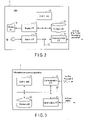
- FIGS. 3 and 4 are block diagrams respectively illustrating hardware and software configurations of the information processing apparatus 2.
- the information processing apparatus 2 includes, for example, a mobile information terminal such as a smartphone or a personal computer.
- the information processing apparatus 2 is structured such that a storage unit 22, an input/output interface (input/output I/F) 23, and a communication interface (communication I/F) 24 are connected via a bus 20 to a control unit 21 having a hardware processor such as a CPU.
- the head mount display 1 is connected to the input/output I/F 23.
- a controller or the like for remote control of the control target device 3 may be connected to the input/output I/F 23.
- the communication I/F 24 includes an interface compatible with, for example, a wireless LAN, a short-range wireless data communication standard (for example, Bluetooth (registered trademark)), or a public mobile communication network, and transmits and receives data to and from the control target device 3 via the network 4.
- the communication I/F 24 may include an interface corresponding to a wired network such as a public wired network, a wired LAN, or a CATV network.
- the storage unit 22 is structured as a storage medium by, for example, combining a non-volatile memory such as a hard disk drive (HDD) or SSD that can be written and read at any time, a non-volatile memory such as a ROM, and a volatile memory such as a RAM.
- the storage area of the storage unit 22 includes a program storage area and a data storage area.
- middleware such as an operating system (OS)
- application programs necessary for executing various types of control processing according to the first embodiment of the present invention are stored.
- a video content storage unit 221 and an auxiliary pattern storage unit 222 are provided in the data storage area.
- the video content storage unit 221 is used to temporarily store captured video data (hereinafter, also referred to as video contents) transmitted from the control target device 3.
- the auxiliary pattern storage unit 222 stores image data of an auxiliary pattern used for reducing VR sickness of the user. The auxiliary pattern and its display processing method will be described in detail later.
- the control unit 21 has a motion data acquisition unit 211, a face direction detection unit 212, a face direction detection data transmission unit 213, a video content receiving unit 214, a video composition unit 215, and an auxiliary pattern display data generation unit 216, as control functions for realizing the first embodiment of the present invention. All of these control functions are implemented by causing the hardware processor of the control unit 21 to execute the application programs stored in the program storage area in the storage unit 22.
- the motion data acquisition unit 211 performs a process of acquiring motion data representing the user's head motion detected by the sensor 16 from the head mount display 1 via the input/output I/F 23.
- the face direction detection unit 212 performs a process of detecting changes in the direction of the user's face based on, for example, the acquired motion data. For example, based on the motion data, the face direction detection unit 212 performs a process of calculating changes in the pan direction and the tilt direction (angle) of the user's face. In addition to the pan direction and the tilt direction, the directions of the face to be detected may include other directions such as the tilt of the neck in the horizontal direction and the zoom direction.
- the face direction detection unit 212 may have a function of detecting changes in the user's line-of-sight direction based on the video captured by the camera.
- the face direction detection data transmission unit 213 performs a process of transmitting the face direction detection data obtained by the face direction detection unit 212 from the communication I/F 24 to the control target device 3 via the network 4.
- the video content receiving unit 214 receives via the communication I/F 24 the video contents sent from the control target device 3 via the network 4, and performs a process of temporarily storing the video contents in the video content storage unit 221.
- the auxiliary pattern display data generation unit 216 reads the image data of the auxiliary pattern from the auxiliary pattern storage unit 222, and generates image data such that the display position of the image data of the auxiliary pattern on the head mount display 1 follows in real time changes in the face direction detected by the face direction detection unit 212.
- the video composition unit 215 generates a composite video in which the image data of the auxiliary pattern generated by the auxiliary pattern display data generation unit 216 is superimposed on the video content read from the video content storage unit 221, and transmits the composite video from the input/output I/F 23 to the head mount display 1.
- FIG. 5 is a flowchart illustrating a processing procedure and processing contents of video display control by the information processing apparatus 2.
- the system administrator uses, for example, his/her own terminal apparatus to generate an auxiliary pattern or acquire an auxiliary pattern from the outside, and stores image data of the auxiliary pattern in the auxiliary pattern storage unit 222.
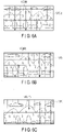
- an auxiliary pattern a grid-like linear pattern L1 including horizontal lines and vertical lines as illustrated in FIGS. 6A to 6C is generated.
- a pattern in which solid lines and broken lines are arranged alternately is illustrated, but only solid lines or only broken lines may be used.
- the size of the grid that is, the spacing between the lines, and the thickness, color, and density of the lines constituting the grid can be arbitrarily set. However, as the setting conditions, it is desirable to allow the user to recognize the auxiliary pattern while maintaining the visibility of the video content.
- the video content including the video captured by the camera on the head of the control target device 3 is transmitted to the information processing apparatus 2 via the network 4.
- This video content is received by the information processing apparatus 2 under the control of the video content receiving unit 214, then transferred from the video composition unit 215 to the head mount display 1 and displayed on the display unit 14.
- the motion of the head is detected by the sensor 16 of the head mount display 1, and the motion data is input to the information processing apparatus 2.
- the information processing apparatus 2 acquires the motion data in step S11 under the control of the motion data acquisition unit 211, and detects the change in the user's face direction from the motion data under the control of the face direction detection unit 212 in step S12.
- the face direction detection unit 212 calculates a change in a vector indicating the direction of the user's face from a 6-axis angular velocity detection signal output from the angular velocity sensor (gyro sensor).
- the information processing apparatus 2 transmits the detection data indicating the change in the orientation of the user's face from the communication I/F 24 to the control target device 3 in step S13 under the control of the face direction detection data transmission unit 213.
- the control target device 3 When the control target device 3 receives the detection data of the face direction, the control target device 3 operates, for example, a servo mechanism to change the imaging direction of the camera based on the detection data of the face direction. As a result, the imaging target area by the camera changes, and the video content including the captured video of the imaging target area during and after the change is returned to the information processing apparatus 2.
- the information processing apparatus 2 performs processing described below in a period of time from when the detection data of the user's face direction is transmitted to the control target device 3 until the video content including the captured video is returned from the control target device 3 in accordance with the detection data.
- the information processing apparatus 2 first reads the image data of the auxiliary pattern from the auxiliary pattern storage unit 222 in step S14 under the control of the auxiliary pattern display data generation unit 216. Then, in step S15, based on the detection data indicating the change in the direction of the user's face obtained in step S12, the information processing apparatus 2 generates image data such that the display position of the auxiliary pattern on the head mount display 1 follows in real time the detected change in the direction of the face.
- the information processing apparatus 2 receives the video content returned from the control target device 3 in step S16 under the control of the video content receiving unit 214. Then, under the control of the video composition unit 215, in step S17, the information processing apparatus 2 superimposes the image data of the auxiliary pattern generated by the auxiliary pattern display data generation unit 216 on the video content returned from the control target device 3 to generate a composite video. Then, the information processing apparatus 2 outputs the data of the composite video from the input/output I/F 23 to the head mount display 1 in step S18.
- the composite video output from the information processing apparatus 2 is displayed on the display unit 14.
- the composite video is a video in which the image of the auxiliary pattern is superimposed on the video content returned from the control target device 3.
- the image of the auxiliary pattern is generated such that the display position changes in real time according to the change in the direction of the user's face.
- the information processing apparatus 2 repeats the operations in steps S11 to S18 during the period of time in which the system is operating.
- FIGS. 6A to 6C are diagrams for describing an example of a change in the display of a composite video on the head mount display 1.
- a composite video in which the auxiliary pattern L1 (t0) is superimposed on a video content VD (t0) is displayed.
- the user moves his/her face diagonally to the upper left direction at time t1.
- the change in the direction of the user's face at this time is notified by the information processing apparatus 2 to the control target device 3, so that the imaging target area by the camera of the control target device 3 changes diagonally to the upper left direction.
- the video content including the captured image according to the change in the imaging target area is returned to the information processing apparatus 2, and is displayed on the head mount display 1 by the information processing apparatus 2.
- the detection data is sent from the information processing apparatus 2 to the control target device 3 via the network 4. Then, the control target device 3 generates the video content corresponding to the detection data.
- This video content is transmitted to the information processing apparatus 2 via the network 4, undergoes auxiliary pattern composition processing in the information processing apparatus 2, and then is displayed on the head mount display 1.
- a drawing delay including a transmission delay before the video content reflecting the change in the direction of the user's face is displayed on the head mount display 1.
- the delay amount of this drawing delay causes time fluctuation (jitter) due to the influence of network congestion degree and CPU load fluctuation.
- the drawing delay (latency) of this video content and jitter of the drawing delay (latency) are major causes of VR sickness for users.
- the display position of the auxiliary pattern L1 (t0) moves on the display screen of the head mount display 1, so as to follow the change in the direction of the user's face in real time.
- FIG. 6B illustrates a display example of the video content VD (t0) and the auxiliary pattern L1 (t1) at this time.
- the display position of the auxiliary pattern L1 (t1) follows the movement of the direction of the user's face in real time. This reduces the effect of the drawing delay (latency) of the video content VD (t0), which suppresses the occurrence of VR sickness in the user.
- FIG. 6C illustrates an example of the display results of the video content VD (t1') and the auxiliary pattern L1 (t1) after the lapse of time corresponding to the drawing delay.
- the display position of the video content VD (t1') catches up with the corresponding position after the change in the direction of the user's face.
- the auxiliary pattern is stored in the storage unit 22 in the information processing apparatus 2 to which the head mount display 1 is connected.
- the information processing apparatus 2 controls the display position of the auxiliary pattern to follow the change in the direction of the user's face in real time, based on the change in the direction of the user's face detected in accordance with detection signal of the motion of the user's head.
- the display position of the video content does not follow the change in the direction of the user's face in real time
- the display position of the auxiliary pattern superimposed on the video content changes so as to follow the change in the direction of the user's face in real time. Therefore, even if a drawing delay (latency) including a transmission delay of the video content occurs or if the delay amount changes with time, that is, even if the drawing delay includes jitter, the influence of the drawing delay (latency) becomes unlikely to exert influence on the user, which makes it possible to reduce the occurrence of VR sickness of the user.
- the occurrence of VR sickness of the user is reduced by moving the display position of the auxiliary pattern stored in advance so as to follow the change in the direction of the user's face. For this reason, the processing load on the CPU in the apparatus can be kept low compared to the case where the reprojection processing is performed on the displayed image, which produces the effect of reducing VR sickness without using an expensive apparatus equipped with a CPU with high processing capacity.
- An information processing apparatus 2 may have a function of monitoring the operating status of at least one of a head mount display 1, the information processing apparatus 2, and a control target device 3, and may display a message indicating the monitoring result by changing the display form of the auxiliary pattern.
- the information processing apparatus 2 monitors the remaining battery power of the head mount display 1 and the information processing apparatus 2. When detecting that the remaining battery power has reduced to a predetermined level or lower, the information processing apparatus 2 notifies the reduction in the remaining battery power by changing the display color, density, or shape of the auxiliary pattern. At that time, as the change pattern of the display form, a change pattern different from the change of the display form following the user's motion or operation, for example, blinking or the like may be used.
- the operating status of the head mount display 1, the information processing apparatus 2, and the control target device 3 may not be monitored based on the remaining battery power. For example, the operating status may be monitored based on other abnormal operating conditions such as abnormal signal cable connection, communication failure, abnormal operational state of the control target device 3.
- the present invention is not limited to the above embodiments as they are, and in the implementation stage, the components can be embodied in modified manners without departing from the scope of the present invention.
- various inventions can be formed by appropriately combining the plurality of components disclosed in the above embodiments. For example, some components may be removed from all the components illustrated in the embodiments. Further, components from different embodiments may be combined as appropriate.
Landscapes
- Engineering & Computer Science (AREA)
- Theoretical Computer Science (AREA)
- Physics & Mathematics (AREA)
- General Physics & Mathematics (AREA)
- General Engineering & Computer Science (AREA)
- Computer Hardware Design (AREA)
- Human Computer Interaction (AREA)
- Multimedia (AREA)
- Signal Processing (AREA)
- Optics & Photonics (AREA)
- Controls And Circuits For Display Device (AREA)
- User Interface Of Digital Computer (AREA)
Applications Claiming Priority (2)
| Application Number | Priority Date | Filing Date | Title |
|---|---|---|---|
| JP2019137237A JP6655751B1 (ja) | 2019-07-25 | 2019-07-25 | 映像表示制御装置、方法およびプログラム |
| PCT/JP2020/010533 WO2021014673A1 (fr) | 2019-07-25 | 2020-03-11 | Dispositif, procédé et programme de commande d'affichage d'image |
Publications (2)
| Publication Number | Publication Date |
|---|---|
| EP4006894A1 true EP4006894A1 (fr) | 2022-06-01 |
| EP4006894A4 EP4006894A4 (fr) | 2022-07-13 |
Family
ID=69624462
Family Applications (1)
| Application Number | Title | Priority Date | Filing Date |
|---|---|---|---|
| EP20844303.6A Withdrawn EP4006894A4 (fr) | 2019-07-25 | 2020-03-11 | Dispositif, procédé et programme de commande d'affichage d'image |
Country Status (5)
| Country | Link |
|---|---|
| US (1) | US11610343B2 (fr) |
| EP (1) | EP4006894A4 (fr) |
| JP (1) | JP6655751B1 (fr) |
| CN (1) | CN112753066B (fr) |
| WO (1) | WO2021014673A1 (fr) |
Families Citing this family (1)
| Publication number | Priority date | Publication date | Assignee | Title |
|---|---|---|---|---|
| JP6801136B1 (ja) * | 2020-05-14 | 2020-12-16 | エヌ・ティ・ティ・コミュニケーションズ株式会社 | 遠隔制御システムとその遠隔作業装置、映像処理装置およびプログラム |
Family Cites Families (36)
| Publication number | Priority date | Publication date | Assignee | Title |
|---|---|---|---|---|
| US6497649B2 (en) * | 2001-01-21 | 2002-12-24 | University Of Washington | Alleviating motion, simulator, and virtual environmental sickness by presenting visual scene components matched to inner ear vestibular sensations |
| WO2004061519A1 (fr) | 2002-12-24 | 2004-07-22 | Nikon Corporation | Casque de visualisation |
| JP4366943B2 (ja) * | 2003-01-31 | 2009-11-18 | 株式会社ニコン | ヘッドマウントディスプレイ |
| JP2004233903A (ja) * | 2003-01-31 | 2004-08-19 | Nikon Corp | ヘッドマウントディスプレイ |
| US7918781B1 (en) * | 2006-03-22 | 2011-04-05 | The United States Of America As Represented By The Secretary Of The Army | Systems and methods for suppressing motion sickness |
| GB201103705D0 (en) * | 2011-03-04 | 2011-04-20 | Smoker Elizabeth A | Apparatus for, and method of, detecting, measuring and assessing operator fatigue |
| JP2013200440A (ja) * | 2012-03-26 | 2013-10-03 | Mitsubishi Electric Corp | 映像表示装置 |
| US11266919B2 (en) * | 2012-06-29 | 2022-03-08 | Monkeymedia, Inc. | Head-mounted display for navigating virtual and augmented reality |
| JPWO2014077046A1 (ja) * | 2012-11-13 | 2017-01-05 | ソニー株式会社 | 画像表示装置及び画像表示方法、移動体装置、画像表示システム、並びにコンピューター・プログラム |
| US9996150B2 (en) * | 2012-12-19 | 2018-06-12 | Qualcomm Incorporated | Enabling augmented reality using eye gaze tracking |
| JP6111659B2 (ja) * | 2012-12-28 | 2017-04-12 | セイコーエプソン株式会社 | 表示装置、および、表示装置の制御方法 |
| JP6375591B2 (ja) * | 2013-01-15 | 2018-08-22 | セイコーエプソン株式会社 | 頭部装着型表示装置、頭部装着型表示装置の制御方法、および、画像表示システム |
| JP6264855B2 (ja) * | 2013-11-18 | 2018-01-24 | セイコーエプソン株式会社 | 頭部装着型表示装置および頭部装着型表示装置の制御方法 |
| US20150062164A1 (en) * | 2013-09-05 | 2015-03-05 | Seiko Epson Corporation | Head mounted display, method of controlling head mounted display, computer program, image display system, and information processing apparatus |
| JP6353214B2 (ja) * | 2013-11-11 | 2018-07-04 | 株式会社ソニー・インタラクティブエンタテインメント | 画像生成装置および画像生成方法 |
| CN105980962B (zh) | 2014-02-17 | 2019-07-23 | 索尼公司 | 信息处理设备和信息处理方法 |
| CN105301771B (zh) * | 2014-06-06 | 2020-06-09 | 精工爱普生株式会社 | 头部佩戴型显示装置、检测装置、控制方法以及计算机程序 |
| JP2016031439A (ja) * | 2014-07-28 | 2016-03-07 | ソニー株式会社 | 情報処理装置及び情報処理方法、コンピューター・プログラム、並びに画像表示システム |
| JP2016033759A (ja) * | 2014-07-31 | 2016-03-10 | セイコーエプソン株式会社 | 表示装置、表示装置の制御方法、および、プログラム |
| US10269132B2 (en) * | 2014-07-31 | 2019-04-23 | Sony Corporation | Displaying images according to head posture and camera posture |
| US9898868B2 (en) * | 2014-11-06 | 2018-02-20 | Seiko Epson Corporation | Display device, method of controlling the same, and program |
| US9804669B2 (en) * | 2014-11-07 | 2017-10-31 | Eye Labs, Inc. | High resolution perception of content in a wide field of view of a head-mounted display |
| JP2017054457A (ja) * | 2015-09-11 | 2017-03-16 | 株式会社コーエーテクモゲームス | 情報処理装置、表示制御方法、及び表示制御プログラム |
| JP6362631B2 (ja) * | 2016-01-15 | 2018-07-25 | 株式会社meleap | 画像表示システム、画像表示システムの制御方法、画像配信システムおよびヘッドマウントディスプレイ |
| US10089725B2 (en) * | 2016-02-09 | 2018-10-02 | Google Llc | Electronic display stabilization at a graphics processing unit |
| JPWO2017159063A1 (ja) * | 2016-03-14 | 2019-01-17 | ソニー株式会社 | 表示装置並びに情報処理端末装置 |
| JP6620063B2 (ja) | 2016-04-21 | 2019-12-11 | 株式会社ソニー・インタラクティブエンタテインメント | 画像処理装置および画像処理方法 |
| JP6373920B2 (ja) * | 2016-09-14 | 2018-08-15 | 株式会社バンダイナムコエンターテインメント | シミュレーションシステム及びプログラム |
| US10204395B2 (en) * | 2016-10-19 | 2019-02-12 | Microsoft Technology Licensing, Llc | Stereoscopic virtual reality through caching and image based rendering |
| KR102927278B1 (ko) * | 2016-12-26 | 2026-02-13 | 엘지디스플레이 주식회사 | 헤드 마운티드 디스플레이 및 그 제어 방법 |
| US11025918B2 (en) * | 2016-12-29 | 2021-06-01 | Sony Interactive Entertainment Inc. | Foveated video link for VR, low latency wireless HMD video streaming with gaze tracking |
| JP2018157319A (ja) * | 2017-03-16 | 2018-10-04 | 本田技研工業株式会社 | コンテンツ視聴装置、コンテンツ提供方法、及び移動体 |
| EP3633627B1 (fr) * | 2017-05-24 | 2025-01-15 | Furuno Electric Co., Ltd. | Imagerie en réalité augmentée indiquant une situation autour d'un corps mobile sur une surface d'eau |
| JP6278546B1 (ja) * | 2017-06-02 | 2018-02-14 | 株式会社コロプラ | 情報処理方法、装置、および当該情報処理方法をコンピュータに実行させるためのプログラム |
| JP6944863B2 (ja) | 2017-12-12 | 2021-10-06 | 株式会社ソニー・インタラクティブエンタテインメント | 画像補正装置、画像補正方法およびプログラム |
| US20210065427A1 (en) * | 2019-08-30 | 2021-03-04 | Shopify Inc. | Virtual and augmented reality using light fields |
-
2019
- 2019-07-25 JP JP2019137237A patent/JP6655751B1/ja active Active
-
2020
- 2020-03-11 WO PCT/JP2020/010533 patent/WO2021014673A1/fr not_active Ceased
- 2020-03-11 EP EP20844303.6A patent/EP4006894A4/fr not_active Withdrawn
- 2020-03-11 CN CN202080005035.8A patent/CN112753066B/zh active Active
-
2021
- 2021-03-08 US US17/194,370 patent/US11610343B2/en active Active
Also Published As
| Publication number | Publication date |
|---|---|
| JP6655751B1 (ja) | 2020-02-26 |
| US11610343B2 (en) | 2023-03-21 |
| CN112753066B (zh) | 2024-03-22 |
| CN112753066A (zh) | 2021-05-04 |
| US20210192805A1 (en) | 2021-06-24 |
| EP4006894A4 (fr) | 2022-07-13 |
| JP2021022075A (ja) | 2021-02-18 |
| WO2021014673A1 (fr) | 2021-01-28 |
Similar Documents
| Publication | Publication Date | Title |
|---|---|---|
| US11119319B2 (en) | Rendering device, head-mounted display, image transmission method, and image correction method | |
| US10629107B2 (en) | Information processing apparatus and image generation method | |
| US11099392B2 (en) | Stabilized and tracked enhanced reality images | |
| US10277814B2 (en) | Display control method and system for executing the display control method | |
| US10477198B2 (en) | Display control method and system for executing the display control method | |
| JP6751205B2 (ja) | ディスプレイ装置及びその制御方法 | |
| EP3683656A1 (fr) | Procédé et appareil de génération d'interface de réalité virtuelle | |
| US12231781B2 (en) | Remote control system, and remote operation apparatus, video image processing apparatus, and computer-readable medium | |
| CN107851334A (zh) | 信息处理装置 | |
| US10771707B2 (en) | Information processing device and information processing method | |
| WO2016163183A1 (fr) | Système de visiocasque et programme informatique pour la présentation d'un environnement ambiant d'espace réel d'un utilisateur dans un espace virtuel immersif | |
| US10356219B2 (en) | Image transmission apparatus, information processing terminal, image transmission method, information processing method, program, and information storage medium | |
| US11474595B2 (en) | Display device and display device control method | |
| US11610343B2 (en) | Video display control apparatus, method, and non-transitory computer readable medium | |
| US10540826B2 (en) | Method of playing virtual reality image and program using the same | |
| EP4443273A1 (fr) | Appareil de commande d'affichage, procédé de commande d'affichage et programme | |
| JPWO2019229816A1 (ja) | 画像生成装置、画像生成方法、およびプログラム | |
| US20230071690A1 (en) | Remote control system, remote operation apparatus, video image processing apparatus, and computer-readable medium | |
| KR101315398B1 (ko) | 3차원 증강 현실 표시 장치 및 방법 | |
| WO2021182124A1 (fr) | Dispositif et procédé de traitement d'informations | |
| CN108140357A (zh) | 信息处理装置 | |
| US20260082022A1 (en) | Information processing device, display device, and image sharing system | |
| JP2024127082A (ja) | 情報処理装置、情報処理装置の制御方法、及びプログラム | |
| KR20200011656A (ko) | 사용자의 위치와 시선 정보를 통한 증강현실 환경 디스플레이 제어 시스템 | |
| JP6427298B1 (ja) | 情報処理システム |
Legal Events
| Date | Code | Title | Description |
|---|---|---|---|
| STAA | Information on the status of an ep patent application or granted ep patent |
Free format text: STATUS: THE INTERNATIONAL PUBLICATION HAS BEEN MADE |
|
| PUAI | Public reference made under article 153(3) epc to a published international application that has entered the european phase |
Free format text: ORIGINAL CODE: 0009012 |
|
| STAA | Information on the status of an ep patent application or granted ep patent |
Free format text: STATUS: REQUEST FOR EXAMINATION WAS MADE |
|
| 17P | Request for examination filed |
Effective date: 20210309 |
|
| AK | Designated contracting states |
Kind code of ref document: A1 Designated state(s): AL AT BE BG CH CY CZ DE DK EE ES FI FR GB GR HR HU IE IS IT LI LT LU LV MC MK MT NL NO PL PT RO RS SE SI SK SM TR |
|
| A4 | Supplementary search report drawn up and despatched |
Effective date: 20220615 |
|
| RIC1 | Information provided on ipc code assigned before grant |
Ipc: G09G 3/00 20060101ALN20220610BHEP Ipc: G09G 5/38 20060101ALI20220610BHEP Ipc: G09G 5/377 20060101AFI20220610BHEP |
|
| STAA | Information on the status of an ep patent application or granted ep patent |
Free format text: STATUS: THE APPLICATION HAS BEEN WITHDRAWN |
|
| DAV | Request for validation of the european patent (deleted) | ||
| DAX | Request for extension of the european patent (deleted) | ||
| 18W | Application withdrawn |
Effective date: 20221014 |