EP4006908A1 - Gen-ausrichtungstechnik - Google Patents
Gen-ausrichtungstechnik Download PDFInfo
- Publication number
- EP4006908A1 EP4006908A1 EP20849621.6A EP20849621A EP4006908A1 EP 4006908 A1 EP4006908 A1 EP 4006908A1 EP 20849621 A EP20849621 A EP 20849621A EP 4006908 A1 EP4006908 A1 EP 4006908A1
- Authority
- EP
- European Patent Office
- Prior art keywords
- gene
- subsequence
- tested
- alignment
- reference gene
- Prior art date
- Legal status (The legal status is an assumption and is not a legal conclusion. Google has not performed a legal analysis and makes no representation as to the accuracy of the status listed.)
- Pending
Links
Images






Classifications
-
- G—PHYSICS
- G16—INFORMATION AND COMMUNICATION TECHNOLOGY [ICT] SPECIALLY ADAPTED FOR SPECIFIC APPLICATION FIELDS
- G16B—BIOINFORMATICS, i.e. INFORMATION AND COMMUNICATION TECHNOLOGY [ICT] SPECIALLY ADAPTED FOR GENETIC OR PROTEIN-RELATED DATA PROCESSING IN COMPUTATIONAL MOLECULAR BIOLOGY
- G16B30/00—ICT specially adapted for sequence analysis involving nucleotides or amino acids
- G16B30/10—Sequence alignment; Homology search
-
- Y—GENERAL TAGGING OF NEW TECHNOLOGICAL DEVELOPMENTS; GENERAL TAGGING OF CROSS-SECTIONAL TECHNOLOGIES SPANNING OVER SEVERAL SECTIONS OF THE IPC; TECHNICAL SUBJECTS COVERED BY FORMER USPC CROSS-REFERENCE ART COLLECTIONS [XRACs] AND DIGESTS
- Y02—TECHNOLOGIES OR APPLICATIONS FOR MITIGATION OR ADAPTATION AGAINST CLIMATE CHANGE
- Y02A—TECHNOLOGIES FOR ADAPTATION TO CLIMATE CHANGE
- Y02A90/00—Technologies having an indirect contribution to adaptation to climate change
- Y02A90/10—Information and communication technologies [ICT] supporting adaptation to climate change, e.g. for weather forecasting or climate simulation
Definitions
- This application relates to the field of optical technologies, and in particular, to a gene alignment technology.
- Deoxyribonucleic acid (Deoxyribonucleic acid, DNA) is a main chemical constituent of a chromosome and is also a material for making up a gene.
- the gene (Gene) is a DNA sequence that carries genetic information, is also referred to as a genetic factor, and is a basic structural unit and functional unit of a genetic material that controls biological traits. The gene expresses, by guiding synthesis of proteins, the genetic information carries in the gene, to control trait performance of a biont.
- HGP Human Genome Project
- DNA sequence alignment is a premise of gene recognition, information analysis, structure prediction, and the like. Same and different sites and regions are found through alignment of a plurality of DNA sequences, to help determine homology, variation points, and sources of to-be-tested genes.
- This application provides a gene alignment technology, to increase DNA alignment efficiency.
- an embodiment of the present invention provides a gene alignment method.
- the method is applied to a computer system including an optical computing chip.
- a processor of the computer system may obtain a first group of gene fragments from a gene database based on a to-be-tested gene sequence, and input the to-be-tested gene sequence and a plurality of reference gene fragments in the first group of gene fragments into the optical computing chip to perform optical alignment.
- the gene database includes a plurality of reference gene fragments of a reference gene sequence, and the first group of gene fragments includes a plurality of reference gene fragments that match some bases of the to-be-tested gene sequence.
- the gene alignment method provided in this embodiment of the present invention two manners, namely, database search and optical autocorrelation alignment, are combined, and initial matching is performed on the to-be-tested gene sequence by using the constructed gene database, to screen out the first group of reference gene fragments that may match the to-be-tested gene sequence.
- initial matching is performed on the to-be-tested gene sequence by using the constructed gene database, to screen out the first group of reference gene fragments that may match the to-be-tested gene sequence.
- a quantity of reference gene fragments that need to be thoroughly aligned can be greatly reduced.
- optical alignment is further performed between the to-be-tested gene sequence and the plurality of reference gene fragments in the first group of reference gene fragments by using the optical computing chip.
- An alignment speed of optical alignment performed by the optical computing chip is faster than an alignment speed of a method of electrical gene alignment. Therefore, the gene alignment method provided in this embodiment of the present invention also greatly increases alignment efficiency.
- the processor may obtain the first group of gene fragments from the database based on the some bases of the to-be-tested gene sequence.
- the first group of gene fragments is obtained from the database based on the first m bases and the last n bases of the to-be-tested gene sequence, where both a value of m and a value of n are greater than 0, and a sum of m and n is less than a quantity of bases in the to-be-tested gene sequence.
- the values of m and n may be determined based on factors such as a length of the to-be-tested gene sequence and a length of the reference gene sequence.
- the database may be a key-value (key-value) database, where key indicates some bases of the plurality of reference gene fragments in the reference gene sequence.
- the values indicate locations of the plurality of reference gene fragments in the reference gene sequence.
- the method further includes: when determining, based on an output result of the optical computing chip, that a similarity degree between the to-be-tested gene sequence and a first gene fragment in the first group of gene fragments is less than a first threshold and greater than a second threshold, obtaining a plurality of reference gene subsequences from the reference gene sequence; and inputting the to-be-tested gene sequence and a first reference gene subsequence in the plurality of reference gene subsequences into the optical computing chip to perform optical alignment, to obtain a first similarity degree between the to-be-tested gene sequence and the first reference gene subsequence, where each reference gene subsequence is a part of the reference gene sequence.
- a similarity degree between the to-be-tested gene sequence and at least one gene fragment in the first group of gene fragments is less than the first threshold and greater than the second threshold, it indicates that a matched reference gene fragment is likely to be found for the to-be-tested gene sequence in the reference gene sequence. Further alignment is required. Therefore, optical alignment may be further performed between the to-be-tested gene sequence and the plurality of reference gene subsequences of the reference gene sequence, so that a reference gene segment that matches at least some segments of the to-be-tested gene sequence can be quickly found.
- the method may further include: determining that the first similarity degree is greater than a third threshold and less than a fourth threshold; and in response to the determining, obtaining a first to-be-tested gene subsequence and a second to-be-tested gene subsequence based on the to-be-tested gene sequence, where the fourth threshold is not greater than the first threshold, and some bases of the first to-be-tested gene subsequence are the same as some bases of the second to-be-tested gene subsequence.
- the first to-be-tested gene subsequence and the first reference gene subsequence are input into the optical computing chip to perform optical alignment, to obtain a second similarity degree; and the second to-be-tested gene subsequence and the first reference gene subsequence are input into the optical computing chip to perform optical alignment, to obtain a third similarity degree.
- the to-be-tested gene sequence may be further split.
- the first to-be-tested gene subsequence and the second to-be-tested gene subsequence that are obtained after splitting are separately aligned with the first reference gene subsequence, so that some segments that are of the to-be-tested gene sequence and that match the first reference gene subsequence can be located as soon as possible. Moreover, because this maximum similarity matching method can allow base deletion, a deletion part or a variant part in the to-be-tested gene sequence can be exactly located.
- the first to-be-tested gene subsequence may include bases of a first preset length obtained from a head-to-tail direction of the to-be-tested gene sequence.
- the second to-be-tested gene subsequence may include bases of the first preset length obtained from a tail-to-head direction of the to-be-tested gene sequence.
- the some bases of the first to-be-tested gene subsequence overlap with the some bases of the second to-be-tested gene subsequence.
- the method further includes: when the second similarity degree is greater than the fourth threshold, recording a location of the first reference gene subsequence in the reference gene sequence. In this manner, when the second similarity degree between the first to-be-tested gene subsequence and the first reference gene subsequence is greater than the fourth threshold, it may be determined that the first to-be-tested gene subsequence matches the first reference gene subsequence at a maximum similarity degree. In this way, the location of the first reference gene subsequence in the reference gene sequence can be recorded, and a segment that matches the first to-be-tested gene subsequence at a maximum similarity degree is obtained.
- the method further includes: when the third similarity degree is greater than the third threshold and less than the fourth threshold, obtaining a first to-be-tested gene subsequence unit and a second to-be-tested gene subsequence unit based on the second to-be-tested gene subsequence; inputting the first to-be-tested gene subsequence unit and the first reference gene subsequence into the optical computing chip to perform optical alignment; and inputting the second to-be-tested gene subsequence unit and the first reference gene subsequence into the optical computing chip to perform optical alignment.
- Some bases of the first to-be-tested gene subsequence unit are the same as some bases of the second to-be-tested gene subsequence unit.
- splitting and alignment may continue to be performed on the second to-be-tested gene subsequence. Therefore, based on this recursive searching manner, a fragment that matches at least some fragments of the second to-be-tested gene sequence at a maximum similarity degree can be quickly located. Because this maximum similarity matching method can allow base deletion, a gene deletion point and a genovariation point can be exactly located.
- the method further includes: inputting the to-be-tested gene sequence and a second reference gene subsequence in the plurality of reference gene subsequences into the optical computing chip to perform optical alignment, to obtain a fourth similarity degree between the to-be-tested gene sequence and the second reference gene subsequence; and inputting the to-be-tested gene sequence and a third reference gene subsequence in the plurality of reference gene subsequences into the optical computing chip to perform optical alignment, to obtain a fifth similarity degree between the to-be-tested gene sequence and the third reference gene subsequence, where the third reference gene subsequence is a reference gene subsequence immediately adjacent to the second reference gene subsequence.
- a fourth reference gene subsequence is obtained based on the second reference gene subsequence and the third reference gene subsequence, and the to-be-tested gene sequence and the fourth reference gene subsequence are input into the optical computing chip to perform optical alignment.
- the fourth reference gene subsequence includes some bases of the second reference gene subsequence and some bases of the third reference gene subsequence.
- a location of the reference gene subsequence may be adjusted in time.
- the fourth reference gene subsequence is obtained by obtaining continuous parts from the second reference gene subsequence and the third reference gene subsequence, so that a segment that matches the to-be-tested gene sequence at a maximum similarity degree can be found from the fourth reference gene subsequence as soon as possible, and the to-be-tested gene fragment does not need to be further aligned with a reference gene subsequence following the third reference gene subsequence.
- a probability and a speed of obtaining a maximum similarity gene segment can be increased, and a quantity of alignment times can be reduced.
- some reference gene fragments may be separately obtained from the second reference gene subsequence and the third reference gene subsequence based on a ratio of the fourth similarity degree to the fifth similarity degree to constitute the fourth reference gene subsequence.
- the method further includes: determining, based on an output result of the optical computing chip, that a second gene fragment in the first group of gene fragments matches the to-be-tested gene sequence; and recording a location of the second gene fragment in the reference gene sequence.
- the inputting the to-be-tested gene sequence and a plurality of reference gene fragments in the first group of gene fragments into the optical computing chip to perform optical alignment includes: separately performing optical encoding on the to-be-tested gene sequence and the plurality of reference gene fragments in the first group of gene fragments; and separately inputting optical code of the to-be-tested gene sequence and optical code of the plurality of gene fragments in the first group of gene sequences into the optical computing chip to perform optical alignment.
- optical encoding may be performed on the to-be-tested gene sequence and the plurality of reference gene fragments based on light intensity information and/or light spatial information.
- an embodiment of the present invention provides a gene alignment apparatus, including a processor and an optical computing chip.
- the processor is configured to obtain a first group of gene fragments from a database based on a to-be-tested gene sequence, where the database system includes a plurality of reference gene fragments of a reference gene sequence, and the first group of gene fragments includes a plurality of reference gene fragments that match some bases of the to-be-tested gene sequence.
- the optical computing chip is connected to the processor and configured to perform optical alignment between the to-be-tested gene sequence and the plurality of reference gene fragments in the first group of gene fragments.
- the processor may obtain the first group of gene fragments from the database based on the some bases of the to-be-tested gene sequence.
- the first group of gene fragments is obtained from the database based on the first m bases and the last n bases of the to-be-tested gene sequence, where both a value of m and a value of n are greater than 0, and a sum of m and n is less than a quantity of bases in the to-be-tested gene sequence.
- the database may be a key-value (key-value) database, where key indicates some bases of the plurality of reference gene fragments in the reference gene sequence, and values indicate locations of the plurality of reference gene fragments in the reference gene sequence.
- the processor is further configured to: determine, based on an output result of the optical computing chip, that a similarity degree between the to-be-tested gene sequence and a first gene fragment in the first group of gene fragments is less than a first threshold and greater than a second threshold; and obtain a plurality of reference gene subsequences from the reference gene sequence, where each reference gene subsequence is a part of the reference gene sequence.
- the optical computing chip is further configured to perform optical alignment between the to-be-tested gene sequence and a first reference gene subsequence in the plurality of reference gene subsequences, to obtain a first similarity degree between the to-be-tested gene sequence and the first reference gene subsequence.
- the processor is further configured to: determine that the first similarity degree is greater than a third threshold and less than a fourth threshold, where the fourth threshold is not greater than the first threshold; and in respond to the determining, obtain a first to-be-tested gene subsequence and a second to-be-tested gene subsequence based on the to-be-tested gene sequence, where some bases of the first to-be-tested gene subsequence are the same as some bases of the second to-be-tested gene subsequence.
- the optical computing chip is further configured to: perform optical alignment between the first to-be-tested gene subsequence and the first reference gene subsequence to obtain a second similarity degree; and perform optical alignment between the second to-be-tested gene subsequence and the first reference gene subsequence to obtain a third similarity degree.
- the processor is further configured to: when the second similarity degree is greater than the fourth threshold, record a location of the first reference gene subsequence in the reference gene sequence.
- the processor is further configured to: when the third similarity degree is greater than the third threshold and less than the fourth threshold, obtain a first to-be-tested gene subsequence unit and a second to-be-tested gene subsequence unit based on the second to-be-tested gene subsequence, where some bases of the first to-be-tested gene subsequence unit are the same as some bases of the second to-be-tested gene subsequence unit.
- the optical computing chip is further configured to perform optical alignment between the first to-be-tested gene subsequence unit and the first reference gene subsequence; and perform optical alignment between the second to-be-tested gene subsequence unit and the first reference gene subsequence.
- the optical computing chip is further configured to: perform optical alignment between the to-be-tested gene sequence and a second reference gene subsequence in the plurality of reference gene subsequences; and perform optical alignment between the to-be-tested gene sequence and a third reference gene subsequence in the plurality of reference gene subsequences, where the third reference gene subsequence is a reference gene subsequence immediately adjacent to the second reference gene subsequence.
- the processor is further configured to determine that a sum of a fourth similarity degree between the to-be-tested gene sequence and the second reference gene subsequence and a fifth similarity degree between the to-be-tested gene sequence and the third reference gene subsequence is greater than the first threshold; obtain a fourth reference gene subsequence based on the second reference gene subsequence and the third reference gene subsequence; and input the to-be-tested gene sequence and the fourth reference gene subsequence into the optical computing chip to perform optical alignment, where the fourth reference gene subsequence includes some bases of the second reference gene subsequence and some bases of the third reference gene subsequence.
- the processor is further configured to: determine, based on an output result of the optical computing chip, that a second gene fragment in the first group of gene fragments matches the to-be-tested gene sequence; and record a location of the second gene fragment in the reference gene sequence.
- the processor is further configured to: separately perform optical encoding on the to-be-tested gene sequence and the plurality of reference gene fragments in the first group of gene fragments; and separately input optical code of the to-be-tested gene sequence and optical code of the plurality of gene fragments in the first group of gene sequences into the optical computing chip to perform optical alignment.
- an embodiment of the present invention provides an alignment apparatus, including a processor and an optical computing chip.
- the processor is configured to obtain a first group of reference objects from a database based on a to-be-matched first object, where the first group of reference objects includes a plurality of reference objects whose some features are the same as some features of the first object.
- the optical computing chip is connected to the processor and configured to perform optical alignment between the first object and the plurality of reference objects.
- the alignment apparatus provided in this embodiment of the present invention, two manners, namely, database search and optical alignment, are combined. After to-be-aligned reference objects are screened by using the database, a quantity of reference objects that need to be thoroughly aligned can be greatly reduced. In addition, an alignment speed can be greatly increased by using the optical computing chip for alignment.
- the alignment apparatus provided in this embodiment of the present invention can be applied not only to a gene testing scenario, but also to various scenarios in which massive data needs to be aligned.
- the processor is further configured to: determine, based on an output result of the optical computing chip, that a similarity degree between the first object and a first reference object in the first group of reference objects is less than a first threshold and greater than a second threshold; and obtain a plurality of reference subobjects based on a standard object, where each reference subobject is a part of the reference object.
- the optical computing chip is further configured to perform optical alignment between the first object and a first reference subobject in the plurality of reference subobjects, to obtain a first similarity degree between the first object and the first reference subobject.
- the processor is further configured to: determine that the first similarity degree is greater than a third threshold and less than a fourth threshold; and in response to the determining, obtain a first subobject and a second subobject based on the first object, where the fourth threshold is not greater than the first threshold, and some data of the first subobject is the same as some data of the second subobject.
- the optical computing chip is further configured to perform optical alignment between the first subobject and the first reference subobject to obtain a second similarity degree; and perform optical alignment between the second subobject and the first reference subobject to obtain a third similarity degree.
- the processor is further configured to: when the second similarity degree is greater than the fourth threshold, record a location of the first reference subobject in the standard object.
- this application further provides an alignment apparatus, including functional modules configured to implement the gene alignment method in any one of the first aspect or the possible implementations of the first aspect, such as an obtaining module, an alignment module, a result processing module, and a determining module.
- this application further provides a computer program product, including program code, where instructions included in the program code are executed by a computer, to implement the gene alignment method in any one of the first aspect and the possible implementations of the first aspect.
- this application further provides a computer-readable storage medium, where the computer-readable storage medium is configured to store program code, and instructions included in the program code are executed by a computer, to implement the gene alignment method in any one of the first aspect and the possible implementations of the first aspect.
- DNA sequencing data has explosively increased due to rapid development of deoxyribonucleic acid (Deoxyribonucleic acid, DNA) sequencing technologies. Therefore, how to increase a DNA alignment speed is a technical problem that urgently needs to be resolved.
- a search rate is usually accelerated by constructing an index for a reference gene sequence in a computer system. Essence of the index is to increase search efficiency by optimizing a data structure.
- index optimization there is a bottleneck in index optimization, and it takes lots of time to simultaneously create a plurality of responsible indexes. Therefore, efficiency of this gene alignment method is difficult to withstand a large increase in the DNA sequencing data.
- a gene alignment solution provided in the embodiments of the present invention can greatly increase a gene alignment speed, and gene alignment can be quickly implemented even when massive gene sequencing data being processed.
- a gene refers to genetic information that controls biological traits, and is usually carried by a DNA sequence.
- the gene may also be considered as a basic genetic unit, namely, a functional DNA or ribonucleic acid (Ribonucleic acid, RNA) sequence.
- RNA ribonucleic acid
- a process of figuring out the sequence of the gene is referred to as gene sequencing.
- a to-be-tested gene sequence may also be referred to as reads, is a small sequencing fragment, and is sequencing data generated by a high-throughput sequencing platform. In a process of sequencing an entire genome, hundreds of millions of reads are generated, and then the reads are spliced together to obtain a complete sequence of the genome.
- a reference gene sequence (which may also be referred to as a reference sequence) is a standard sequence that has been verified and edited.
- the reference gene sequence can provide a basis for a functional annotation of a human genome.
- the reference gene sequence provides a stable reference point for mutation analysis, gene expression study, and polymorphism discovery. It should be noticed that, a person skilled in the art can easily understand that the reference gene sequence is also referred to as a gene fragment.
- a base pair is a chemical structure for forming DNA and RNA monomers and encoding genetic information.
- Bases included in base pairs include adenine A, guanine G, thymine T, cytosine C, and uracil U. Strictly speaking, the base pair is a pair of matched bases (namely, A-T, G-C, A-U interactions) connected by hydrogen bonds. The base pair is often used to measure lengths of DNA and RNA (although the RNA is single-stranded).
- FIG. 1 is a schematic diagram of implementing gene alignment by using an optical system according to an embodiment of the present invention.
- a gene alignment apparatus 100 may include a processor 102, a memory 104, and an optical computing chip 106.
- the processor 102 and the memory 104 may be considered as a part of a host 101.
- the optical computing chip 106 may be connected to the host 101 through a host interface.
- the host interface may include a standard host interface and a network interface (network interface).
- the host interface may include a peripheral component interconnect express (Peripheral Component Interconnect Express,PCIe) interface.
- PCIe peripheral component interconnect express
- Data may be sent to the optical computing chip 106 through the host interface, or data processed by the optical computing chip 106 may be sent to the processor 102 through the host interface.
- the processor 102 may monitor a working state of the optical computing chip 106 through the host interface.
- the processor 102 and the memory 104 may alternatively not be used as the part of the host, and the processor 102, the memory 104, and the optical computing chip 106 may be a part of a system on a chip (System on a Chip, SoC.
- the processor (Processor) 102 is an operation core and a control core (Control Core) of the gene alignment apparatus 100.
- the processor 102 may include a plurality of processor cores (core).
- the processor 102 may be a hyperscale integrated circuit.
- An operating system and another software program are installed in the processor 102, so that the processor 102 can access an internal memory 1042, a cache, a magnetic disk, and a peripheral device (for example, the optical computing chip 106 in FIG. 1 ).
- the core in the processor 102 may be, for example, a central processing unit (Central Processing Unit, CPU), a graphics processing unit (Graphics Processing Unit, GPU), or a field programmable gate array (Field Programmable Gate Array, FPGA); or may be another application-specific integrated circuit (Application-Specific Integrated Circuit, ASIC), or the like.
- CPU Central Processing Unit
- GPU Graphics Processing Unit
- FPGA Field Programmable Gate Array
- ASIC Application-Specific Integrated Circuit
- the memory 104 is configured to store data.
- the memory 104 may include other memories that store data, such as the internal memory 1042 and the magnetic disk.
- the internal memory 1042 is a main memory of the host 101.
- the internal memory 1042 may be connected to the processor 102 through a double data rate (double data rate, DDR) bus.
- the internal memory 1042 is usually configured to store various running software in the operating system; input and output data, information exchanged with an external memory, and the like. To increase an access speed of the processor 102, the internal memory 1042 needs to have an advantage of a fast access speed.
- a dynamic random access memory (Dynamic Random Access Memory, DRAM) is usually used as the internal memory 1042.
- the processor 102 can access the internal memory 1042 at a high speed by using a memory controller (not shown in FIG. 1 ), and perform a read operation and a write operation on any storage unit in the internal memory 1042.
- the memory 104 may be configured to store a gene database 1044.
- the gene database 1044 may be a key-value (key-value) database established based on a reference sequence, where key may be obtained based on some bases of a gene fragment, and values may include a location of a reference gene segment corresponding to key in the memory, and may further include a location of the reference gene segment corresponding to key in the reference gene sequence.
- FIG. 2A is a schematic diagram of a gene database according to an embodiment of the present invention.
- the gene database 1044 may include key (key) 1044_1 and value (value) 1044_2. 10 bases are used as an example in key 1044_1 part.
- five bases at the head of a reference segment and five bases at the tail of the reference segment may be separately taken as key.
- how to establish the gene database 1044 is described by using an example in which 150 bases are a length of the reference gene fragment.
- an index table (with only keys) of an empty set is first constructed, where a quantity of rows of the index table is 4 5+5 , and a sorting combination of keys is alphabetical sorting from AAAAAAAAAA to TTTTTTTT.
- a mapping manner is shown in FIG. 2B .
- bases at the head are arranged in a high order and bases at the tail are arranged in a low order. Bases at a same order are advanced in an order of A, C, G, and T.
- a preset base length is successively used as a unit window, and a step length is used as a unit base (namely, one base) to slide on a reference gene sequence, to obtain a plurality of reference gene fragments.
- key of the reference gene fragment may be obtained based on five bases at the head of the reference gene fragment and five bases at the tail of the reference gene fragment.
- a location of the reference gene fragment in the reference gene sequence is recorded in value 1044_2 corresponding to key. For example, a location of the first base of the reference gene fragment may be recorded.
- values of all reference gene fragments namely, location information of the reference gene fragments of the reference gene sequence are obtained.
- the gene database 1044 as shown in FIG. 2A can be established.
- n and m bases directly affect efficiency of an algorithm, and increases of n and m cause a decrease in values (namely, location information) stored in key. If a hardware factor is not considered, an addressing rate for each to-be-tested gene sequence is increased of four times by each time one base is increased. However, because a sequencing error and a genetic mutation limit infinite increases of n and m, increasing n and m may decrease reliability of key. Therefore, values of m and n may be determined based on a requirement, and the length of the reference gene fragment may also be set based on an actual requirement.
- the values of m and n may be determined based on factors such as a length of the to-be-tested gene sequence and a length of the reference gene sequence.
- the length of the reference gene fragment is usually the same as a base length of the to-be-tested gene sequence.
- the optical computing chip 106 may be an on-chip optical computing system.
- FIG. 3 A is a schematic structural diagram of an optical computing chip according to an embodiment of the present invention.
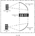
- the optical computing chip 106 may include a light source array 202, a modulator array 204, a detector array 206, a first concave mirror 208, and a second concave mirror 210.
- the light source array 202 is located on an objective focal plane of the first concave mirror 208
- the modulator array 204 is located on an image focal plane of the first concave mirror 208
- the modulator array 204 is also located on an objective focal plane of the second concave mirror 210.
- the detector array 206 is located on an image focal plane of the second concave mirror 210.
- the light source array 202 is configured to modulate and transmit data as a data input unit of the optical computing chip 106.
- the light source array 202 may generate a plurality of optical signals of different light intensities based on input data.
- the first concave mirror 208 is configured to implement standard Fourier transform on the optical signals data sent by the light source array 202.
- the modulator array 204 has two working modes: a recording mode and a modulation mode. The recording mode is used to obtain an image of a spectral plane after the optical signals data sent by the light source array 202 pass through the first concave mirror 208.
- the modulation mode is used to modulate, on the modulator array 204, the image of the spectral plane after the optical signals data sent by the light source array 202 pass through the first concave mirror 208.
- the second concave mirror 210 is configured to implement standard inverse Fourier transform on optical signals that pass through the modulator array 204.
- the detector array 206 is used for light intensity signal detection as a result output unit of the optical computing chip 106.
- FIG. 3B is a schematic structural diagram of still another optical computing chip according to an embodiment of the present invention. Different from the optical computing chip provided in FIG. 3A , in the optical computing chip shown in FIG. 3B , the light source array 202 and the detector array 206 are disposed on a same side of the chip, so that a structure of the entire computing chip is more compact, and a chip size can be reduced. As shown in FIG. 3B , compared with the optical computing chip shown in FIG.
- locations of the first concave mirror 208, the second concave mirror 210, and the modulator array 204 remain unchanged; and focal length locations of the light source array 202, the modulator array 204, and the detector array 206 with respect to the first concave mirror 208 and the second concave mirror 210 also remain unchanged.
- FIG. 3B For implementation of each component shown in FIG. 3B , refer to descriptions of each component in the optical computing chip shown in FIG. 3A . Details are not described herein again.
- FIG. 3A and FIG. 3B are merely schematic structural diagrams of the optical computing chip according to the embodiments of the present invention.
- a specific structure of the optical computing chip 106 is not limited, and an optical computing chip of another structure may alternatively be used.
- the optical computing chip 106 may alternatively be an optical computing chip of another structure implemented by using a principle of a 4F optical computing system.
- FIG. 3C is a schematic diagram of the principle of the 4F optical computing system. As shown in FIG. 3C , a first modulator 302 is located at an object plane focus location of a first convex lens 304.
- a second modulator 306 is located at an image plane focus location of the first convex lens 304, and is located at an object plane focus location of a second convex lens 308.
- a spacing between the first convex lens 304 and the second convex lens 308 is a sum of focal lengths of the two convex lenses (304 and 308).
- a detector 310 is located at an image plane focus location of the second convex lens 308, and a length of the entire system is four times the focal length.
- the detector 310 may obtain an autocorrelation result of the two pieces of data by detecting an intensity of the time domain optical signal that passes through the second convex lens 308. It should be noted that both the first data and the second data loaded onto the optical computing chip may be vectors.
- a process in which the optical computing chip in FIG. 3A to FIG. 3C implements data alignment is obtained by detecting an autocorrelation result of optical signals of two pieces of data in optical space.
- autocorrelation is also referred to as sequence correlation, and is a cross-correlation of a signal with a delayed copy of itself as a function of delay.
- autocorrelation is the similarity between observations as a function of the time lag between them.
- Autocorrelation is a mathematical tool for finding repeating patterns of sequences of random variables.
- an autocorrelation operation can be used to ensure that when a to-be-tested sequence and a target sequence are the same, an autocorrelation result of the sequences appears at an obvious location with a maximum value, and sequence alignment can be easily realized by monitoring occurrence of the maximum value.
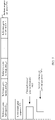
- FIG. 4 is a flowchart of a gene alignment method according to an embodiment of the present invention. The following specifically describes the method shown in FIG. 4 with reference to FIG. 1 .
- detecting one to-be-tested gene sequence is used as an example for description. It may be understood that, even if a plurality of to-be-tested gene sequences are tested at a time in actual application, alignment may be performed for each to-be-tested gene sequence with reference to the embodiments of the present invention.
- the method includes the following steps.
- the processor 102 obtains a first group of gene fragments from the database based on some bases of a to-be-tested gene sequence.
- key of the to-be-tested gene sequence may be obtained in a manner of obtaining key 1044_1 of the gene database 1044.
- key 1044_1 of the gene database 1044 For example, five bases at the head of the to-be-tested gene sequence and five bases at the tail of the to-be-tested gene sequence may be used as key of the to-be-tested gene sequence.
- the gene database 1044 is searched based on key of the to-be-tested gene sequence, to obtain a plurality of values that match key, where the plurality of values are used to indicate possible locations of the to-be-tested gene sequence on a reference gene sequence.
- a plurality of reference gene fragments may be obtained based on a plurality of matched values.
- a plurality of reference gene fragments that match key of the to-be-tested gene sequence are referred to as the first group of gene fragments.
- step 404 optical alignment is performed between the to-be-tested gene sequence and the plurality of reference gene fragments in the first group of gene fragments by using the optical computing chip 106.
- the processor 102 may separately perform optical encoding on the to-be-tested gene sequence and the plurality of reference gene segments, and load optical code of the to-be-tested gene sequence and optical code of the plurality of reference gene segments to the optical computing chip for alignment.
- base strings in the to-be-tested gene sequence and the reference gene fragments may be encoded respectively.
- each point light source is used as a unit cluster of single bases, and four different bases are represented by different degrees of brightness and darkness (0 indicates that the point light source is off, and 1 indicates that the point light source is bright).
- Coding schemes of A, C, G, and T are 0001, 0010, 0100, and 1000, as shown in FIG. 5A .
- the optical code of the to-be-tested gene sequence and the optical code of the plurality of reference gene fragments in the first group of gene fragments can be obtained. Therefore, the optical code of the to-be-tested gene sequence and the optical code of the plurality of reference gene fragments in the first group of gene fragments may be sent to the optical computing chip 106 to perform optical alignment.
- encoding schemes directly affect decoding difficulty and reliability of autocorrelation result output.
- light intensity information and/or light spatial information may be further included in an encoding process.
- a manner of encoding by using the light intensity information may be referred to as an intensity encoding scheme
- a manner of encoding by using the light spatial information may be referred to as a spatial encoding scheme.
- the two encoding schemes may be further combined, and this combined manner may be referred to as a hybrid encoding scheme.
- a light intensity may be modulated by using different voltage amplitudes, and four different bases are represented by using light signals with different intensities.
- the intensity encoding scheme may be shown in FIG. 5B .
- a plurality of point light sources may be used as a unit cluster of single bases, and four different bases are represented by different degrees of brightness and darkness (0 indicates that the point light source is off, and 1 indicates that the point light source is bright).
- the spatial encoding scheme may be shown in FIG. 5C .
- a plurality of optical signals with a same voltage and different light intensities may be used to represent different bases.
- the hybrid encoding scheme may be a scheme of combining intensity encoding and spatial encoding.
- the hybrid encoding scheme may be shown in FIG. 5D .
- a plurality of optical signals with specific different voltages and different light intensities may be combined to represent different bases.
- a specific encoding scheme is not limited in this embodiment of the present invention.
- the light source array 202 may first send a first optical signal based on code of the reversed to-be-tested gene sequence, and Fourier transform is performed on the first optical signal after being reflected by the first concave mirror 208 to convert the first optical signal into a spectrum optical signal.
- the modulator array 204 receives the reflected spectrum optical signal of the first optical signal, and modulates the reflected spectrum optical signal of the first optical signal on the modulator array 204.
- the light source array 202 separately sends a plurality of optical signals based on the optical code of the plurality of reference gene segments in the first group of reference gene segments, so that the optical signals sent based on the optical code of the reference gene segments pass through the first concave mirror 208 and are converted into spectrum optical signals at a location of the modulator array 204, and a multiplication operation is performed, in optical space, between the spectrum optical signals and the reflected signal of the first optical signal.
- the spectrum optical signals output by the modulator array 204 undergo inverse Fourier transform through the second concave mirror 210, and then are converted to time domain optical signals.
- the detector array 206 can separately obtain, by detecting light intensities of the time-domain optical signals output by the second concave mirror 210, matching results between the first optical signal and the optical signals of the plurality of reference gene fragments.
- a person skilled in the art may know that, an autocorrelation result of the two pieces of data is obtained by multiplying and performing inverse Fourier transform on spectrum data.
- the processor 102 determines a similarity degree between the to-be-tested gene sequence and each of the plurality of reference gene fragments based on an output result of the optical computing chip.
- the optical computing chip 106 may send the matching result to the processor 102.
- a light intensity signal obtained through detection by the detector array 206 may be collected by using some peripheral circuits, the collected light intensity signal is converted into an electrical signal, the electrical signal is converted into a digital signal, and then the digital signal is sent to the processor 102.
- the processor 102 can obtain an alignment result between the to-be-tested gene sequence and the reference gene fragment from the optical computing chip 106.
- the detector array 206 may generate a feedback each time an alignment result is obtained, or may generate a feedback when the similarity degree reaches a preset threshold. It should be noted that, in this embodiment of the present invention, the similarity degree is used to indicate a matching degree between the to-be-tested gene sequence and the reference gene fragment.
- step 408 the processor 102 determines whether a similarity degree between the to-be-tested gene segment and a first reference gene segment in the plurality of reference gene segments is greater than or equal to a first threshold, and if the similarity degree is greater than or equal to the first threshold, step 410 is proceeded.
- the method proceeds to step 412.
- the processor 102 may compare the result with the set threshold. A matching result between the to-be-tested gene sequence and any reference gene segment may be aligned with the set threshold.
- the to-be-tested gene sequence and the first reference gene fragment in the first group of reference gene fragments are used as an example for description, where the first reference gene fragment is any reference gene fragment in the first group of reference gene fragments.
- the method proceeds to step 410. Otherwise, the method proceeds to step 412.
- the processor 102 records a location of the first reference gene segment in the reference gene sequence, and ends matching on the to-be-tested gene sequence.
- a matching result that the similarity degree is greater than or equal to the first threshold indicates that the matching is successful.
- the processor 102 may record the location of the first gene segment in the reference gene sequence, and end matching on the to-be-tested gene sequence. A matching process ends. It may be understood that, in this embodiment of the present invention, the similarity degree is used to indicate the matching degree between the to-be-tested gene sequence and the reference gene fragment.
- the first threshold is used to indicate whether a matching criterion of a requirement is met.
- the first threshold may be used to indicate full matching, or may be used to indicate maximum similarity degree matching. If the similarity degree is greater than or equal to the set first threshold, it may be considered that the to-be-tested gene sequence matches the reference gene sequence or the to-be-tested gene sequence matches the reference gene sequence at a maximum similarity degree.
- the first threshold may be 100%, or may be 95%. This is not limited herein.
- the processor 102 determines whether the similarity degree between the to-be-tested gene fragment and the first gene fragment is greater than a second threshold in step 412.
- the method proceeds to step 414, namely, a maximum similarity degree matching procedure. Otherwise, the method proceeds to step 416. It is determined that the to-be-tested gene sequence does not match the first reference gene fragment, and the matching between the to-be-tested gene fragment and the first gene fragment ends.
- the second threshold may be set to 50%.
- the similarity degree between the to-be-tested gene fragment and the first reference gene fragment is less than the first threshold and greater than the second threshold, it indicates that there is a relatively high possibility that the to-be-tested gene sequence can match the reference gene sequence, in other words, some segments in the to-be-tested gene sequence may match the reference gene sequence. Therefore, the to-be-tested gene sequence needs to be further aligned with the reference gene sequence, and the method proceeds to the maximum similarity degree matching procedure.
- step 408 to step 416 in FIG. 4 are described by using an example in which the to-be-tested gene sequence matches the first reference gene segment.
- processing is performed according to step 408 and step 416 separately based on the similarity degree between the to-be-tested gene sequence and each reference gene fragment.
- steps 404 to step 416 may also be sequentially performed on the to-be-tested gene sequence and each reference gene fragment in the first group of reference gene fragments.
- a specific implementation is not limited herein.
- initial matching is performed on the to-be-tested gene sequence by using the constructed gene database, to screen out the first group of reference gene fragments that may match the to-be-tested gene sequence.
- a human reference gene segment is used as an example.
- the human reference gene segment has 3 billion bases, and it takes a lot of time to directly compare the to-be-tested gene segment with the reference gene segments one by one.
- reference gene fragments that need to be aligned may be reduced from 3 billion to several hundreds, thereby greatly reducing a quantity of reference gene fragments that need to be aligned.
- optical alignment is further performed between the to-be-tested gene sequence and the plurality of reference gene fragments in the first group of reference gene fragments by using the optical computing chip.
- An alignment speed of optical alignment performed by the optical computing chip is faster than an alignment speed of a method of electrical gene alignment. Therefore, the gene alignment method provided in this embodiment of the present invention also greatly increases alignment efficiency.
- FIG. 6A to FIG. 6C are a flowchart of still another gene alignment method according to an embodiment of the present invention. The method shown in FIG. 6A to FIG. 6C is still performed by the gene alignment apparatus 100. As shown in FIG. 6A to FIG. 6C , the method may include the following steps.
- the processor 102 obtains a plurality of reference gene subsequences from a reference gene sequence. Specifically, the processor 102 obtains the plurality of reference gene subsequences from the reference gene sequence based on a length of a to-be-tested gene sequence. For example, the plurality of reference gene subsequences may be obtained from the reference gene sequence by using the length of the to-be-tested gene sequence as a window and a sliding step. Alternatively, the reference gene sequence may be split into the plurality of reference gene subsequences based on a base length of the to-be-tested gene sequence. For example, as shown in FIG.
- a plurality of reference gene subsequences may be obtained from the reference gene sequence 700 based on a length of the to-be-tested gene sequence 702. For example, the reference gene sequence has 3 billion bases. If the to-be-tested gene sequence has 150 bases, 0.2 million reference gene subsequences may be obtained.
- step 604 the to-be-tested gene sequence and an i th reference gene subsequence obtained in step 602 are input into the optical computing chip 106 to perform optical alignment.
- An initial value of i is 1, and a value of i is not greater than a quantity of reference gene subsequences obtained in step 602.
- the processor 102 may separately perform optical encoding on the to-be-tested gene sequence and the i th reference gene subsequence; and load optical code of the to-be-tested gene sequence and optical code of the i th reference gene subsequence into the optical computing chip 106 to perform optical alignment, to obtain a similarity degree between the to-be-tested gene sequence and the i th reference gene subsequence.
- the optical computing chip 106 sends an alignment result to the processor 102.
- a similarity degree between the to-be-tested gene sequence and a first reference gene subsequence in the plurality of reference gene subsequences may be referred to as a first similarity degree.
- the to-be-tested gene sequence continues to be aligned with a next reference gene subsequence until optical alignment is completed between the to-be-tested gene sequence and all of the reference gene subsequences obtained in step 602 by using the optical computing chip 106. For example, if the processor 102 determines that the similarity degree between the to-be-tested gene sequence and the i th reference gene subsequence is greater than the third threshold in step 606, the method proceeds to step 610.
- the third threshold may be set to a similarity degree less than 50%. For example, the third threshold may be set to 20%. It may be understood that, in actual application, the third threshold may alternatively be the same as the second threshold. This is not limited herein.
- the processor 102 determines whether the similarity degree between the to-be-tested gene sequence and the i th reference gene subsequence is greater than a fourth threshold in step 610. If the similarity degree between the to-be-tested gene sequence and the i th reference gene subsequence is greater than the fourth threshold, the method proceeds to step 612.
- the fourth threshold is not greater than the first threshold
- the first threshold may be a set threshold used to indicate full matching
- the fourth threshold is a threshold used to indicate maximum similarity degree matching.
- the first threshold may be set to 100%, and the fourth threshold may be set to 95%. It may be understood that, in actual application, the fourth threshold may alternatively be the same as the first threshold. For example, both the first threshold and the fourth threshold may be set to 95%, and are thresholds used to indicate maximum similarity degree matching. This is not limited herein.
- the processor 102 determines that the i th reference gene subsequence is a gene fragment with a maximum similarity degree to the to-be-tested gene sequence, records a location of the i th reference gene subsequence in the reference gene sequence, and ends an alignment procedure of the to-be-tested gene sequence. If the similarity degree between the to-be-tested gene sequence and the i th reference gene subsequence is not greater than the fourth threshold, the method proceeds to step 614.
- step 614 the processor 102 obtains a first to-be-tested gene subsequence and a second to-be-tested gene subsequence based on the to-be-tested gene sequence.
- the processor 102 may obtain a first to-be-tested gene subsequence 7022 and a second to-be-tested gene subsequence 7024 based on the to-be-tested gene sequence 702.
- Some bases of the first to-be-tested gene subsequence 7022 are the same as some bases of the second to-be-tested gene subsequence 7024.
- the first to-be-tested gene subsequence 7022 may include bases of a first preset length obtained from a head-to-tail direction of the to-be-tested gene sequence 702.
- the second to-be-tested gene subsequence 7024 may include bases of the first preset length obtained from a tail-to-head direction of the to-be-tested gene sequence 702.
- the some bases of the first to-be-tested gene subsequence 7022 are the same as the some bases of the second to-be-tested gene subsequence 7024. The method proceeds to step 616.
- step 616 optical alignment is performed between aj th to-be-tested gene subsequence and the i th reference gene subsequence by using the optical computing chip 106.
- An initial value of j is 1, and a value of j may not be greater than a quantity of to-be-tested gene subsequences.
- two to-be-tested gene subsequences are obtained from the to-be-tested gene sequence. Therefore, in this embodiment of the present invention, the value of j is not greater than 2. It may be understood that, if p (p is greater than 2) to-be-tested gene subsequences need to be obtained in actual application, the value of j may not be greater than p.
- the processor 102 also needs to first perform optical encoding on the j th to-be-tested gene subsequence and then load optical code of the j th to-be-tested gene subsequence and the optical code of the i th reference gene subsequence to the optical computing chip 106 to perform optical alignment, to obtain a similarity degree between the j th to-be-tested gene subsequence and the i th reference gene subsequence.
- the method proceeds to step 618.
- the processor 102 determines whether the similarity degree between the j th to-be-tested gene subsequence and the i th reference gene subsequence is greater than the third threshold.
- Optical alignment is performed between the (j + 1) th to-be-tested gene subsequence and the i th reference gene subsequence, to obtain a similarity degree between the (j + 1) th to-be-tested gene subsequence and the i th reference gene subsequence.
- step 618 the method proceeds to step 622, to further determine whether the similarity degree between the j th to-be-tested gene subsequence and the i th reference gene subsequence is greater than the fourth threshold.
- a matching result the first to-be-tested gene subsequence and the first reference gene subsequence by the optical computing chip may be referred to as a second similarity degree.
- a matching result of the second to-be-tested gene subsequence and the first reference gene subsequence by the optical computing chip is referred to as a third similarity degree.
- step 624 A location of a reference gene segment that is in the i th reference gene subsequence and that matches the j th to-be-tested gene subsequence in the reference gene sequence is recorded, and matching on the to-be-tested gene sequence ends.
- step 626 the processor 102 obtains a first to-be-tested gene sequence unit and a second to-be-tested gene sequence unit of the j th to-be-tested gene subsequence, where some bases of the first to-be-tested gene sequence unit are the same as some bases of the second to-be-tested gene sequence unit.
- the first to-be-tested gene sequence unit may include bases of a second preset length obtained from a head-to-tail direction of the j th to-be-tested gene subsequence.
- the second to-be-tested gene sequence unit may include bases of the second preset length obtained from a tail-to-head direction of the j th to-be-tested gene subsequence.
- step 628 optical alignment is performed between a k th to-be-tested gene sequence unit and the i th reference gene subsequence by using the optical computing chip 106.
- An initial value of k is 1, and a value of k is not greater than a quantity of to-be-tested gene sequence units.
- the value of k is not greater than 2.
- the processor 102 may perform optical encoding on the k th to-be-tested gene sequence unit, and separately load optical code of the k th to-be-tested gene sequence unit and the optical code of the i th reference gene subsequence to the optical computing chip 106 to perform optical alignment.
- the method proceeds to step 630.
- the processor 102 determines whether a similarity degree between the k th to-be-tested gene sequence unit and the i th reference gene subsequence is greater than the third threshold.
- Optical alignment is performed between the second to-be-tested gene sequence unit and the i th reference gene subsequence by using the optical computing chip 106.
- step 634 Whether the similarity degree between the k th to-be-tested gene sequence unit and the i th reference gene subsequence is greater than the fourth threshold is determined. If the similarity degree is greater than the fourth threshold, the method proceeds to step 636. A location of a gene fragment that is in the i th reference gene subsequence and that matches the k th to-be-tested gene sequence unit in the reference gene sequence is recorded, and matching is ended.
- matching on the to-be-tested gene sequence may be ended.
- matching on the j th to-be-tested gene subsequence may be ended, or matching on the k th to-be-tested gene sequence unit may be ended. Matching on the (k + 1) th to-be-tested gene sequence unit or matching on the (j + 1) th to-be-tested gene subsequence continues.
- the method proceeds to step 638.
- the k th to-be-tested gene sequence unit continues to be split in a recursive manner, and optical alignment is performed between a subunit of the k th to-be-tested gene sequence unit and the i th reference gene subsequence, until a to-be-tested gene fragment whose similarity degree to the i th reference gene subsequence is greater than the fourth threshold is found.
- a reference gene fragment whose similarity degree to some to-be-tested gene fragments in the to-be-tested gene sequence is greater than the fourth threshold may be referred to as a maximum similarity gene fragment.
- maximum similarity degree matching can be further performed on the to-be-tested gene segment by using the gene alignment method shown in FIG. 6A to FIG. 6C .
- the method shown in FIG. 6A to FIG. 6C can allow that the to-be-tested gene sequence is not completely consistent with the obtained maximum similarity gene fragment, and some bases in the to-be-tested gene sequence may be deleted or may be different from the reference gene fragment. Therefore, a deleted gene or a mutant gene in the to-be-tested gene sequence can be exactly located.
- the gene alignment method provided in this embodiment of the present invention may further include a method procedure shown in FIG. 8 .
- the method shown in FIG. 8 may be after step 604 shown in FIG. 6A to FIG. 6C .
- the method may include the following steps.
- step 802 the processor 102 determines that a first similarity degree between the to-be-tested gene sequence and the i th reference gene subsequence is less than a third threshold.
- step 804 when the processor 102 further determines that a second similarity degree between the to-be-tested gene sequence and the (i + 1) th reference gene subsequence is greater than the third threshold, the method proceeds to step 806.
- the third threshold may be the same as the third threshold set in step 606, for example, may be 50%.
- step 806 the processor further determines whether a sum of the first similarity degree and the second similarity degree is greater than 100%. If the sum of the first similarity degree and the second similarity degree is not greater than 100%, the method proceeds to step 808. Optical alignment is performed between the to-be-tested gene sequence and the (i + 2) th reference gene subsequence by using the optical computing chip 106. If the sum of the first similarity degree and the second similarity degree is greater than 100%, the method proceeds to step 810. In step 810, the processor 102 obtains a new reference gene subsequence based on the i th reference gene subsequence and the (i + 1) th reference gene subsequence.
- some reference gene fragments may be obtained from the i th reference gene subsequence and some reference gene fragments may be obtained from the (i + 1) th reference gene subsequence based on a ratio of the first similarity degree to the second similarity degree to constitute the new reference gene subsequence. For example, if the first similarity degree is 40% and the second similarity degree is 80%, and a length of a reference gene sequence is 150 base pairs, 50 base pairs at the tail of the i th reference gene subsequence and 100 base pairs at the head of the (i + 1) th reference gene subsequence may constitute a new continuous reference subsequence with a length of 150 base pairs.
- Optical alignment is performed between the to-be-tested gene sequence and the obtained new reference subsequence by using the optical computing chip 106.
- Optical alignment method refer to the descriptions of step 604 in FIG. 6A to FIG. 6C .
- a process of aligning on the to-be-tested gene sequence with the obtained new reference subsequence refer to a process of aligning the to-be-tested gene sequence with the i th reference subsequence in FIG. 6A to FIG. 6C .
- a similarity degree between the to-be-tested gene sequence and the new reference gene subsequence is greater than the third threshold, reference may continue to be made to the method in step 610 to step 638 in FIG. 6A to FIG. 6C .
- the new reference subsequence is searched for a reference gene fragment whose similarity degree to the to-be-tested gene sequence is greater than the fourth threshold.
- a reference gene fragment found in the reference gene sequence according to the alignment method shown in FIG. 6A to FIG. 6C and FIG. 8 and whose similarity degree to the to-be-tested gene sequence is greater than the fourth threshold may be referred to as a maximum similarity gene fragment.
- the method shown in FIG. 8 may be used in combination with the method shown in FIG. 6A to FIG. 6C .
- the method shown in FIG. 8 may be performed instead. Therefore, the new reference gene sequence obtained from the i th reference gene subsequence and the (i + 1) th reference gene subsequence can be aligned with the to-be-tested gene sequence.
- FIG. 8 is described by using the to-be-tested gene sequence and the i th reference gene subsequence as an example.
- the i th reference gene subsequence may be any one of the plurality of reference gene subsequences.
- the processor may perform alignment between the to-be-tested gene sequence and a second reference gene subsequence in the plurality of reference gene subsequences.
- a similarity degree between the to-be-tested gene sequence and the second reference gene subsequence is a fourth similarity degree, and the fourth similarity degree is less than the third threshold.
- step 804 the processor 102 determines that a similarity degree between the to-be-tested gene sequence and a third reference gene subsequence in the plurality of reference gene subsequences is a fifth similarity degree, and the fifth similarity degree is greater than the third threshold. If the processor further determines that a sum of the fourth similarity degree and the fifth similarity degree is greater than 100% in step 806, the processor 102 may obtain a new reference gene subsequence based on the second reference gene subsequence and the third reference gene subsequence by using the method shown in FIG. 8 .
- the maximum similarity gene segment of the to-be-tested gene sequence may be further extended on the to-be-tested gene sequence and the reference sequence by using a Smith-Waterman local alignment algorithm, to obtain a longer maximum similarity gene fragment, so as to facilitate further gene analysis of the to-be-tested gene fragment.
- the method shown in the foregoing embodiment is described by using an example in which the to-be-tested gene sequence is aligned with one of the plurality of reference gene subsequences.
- alignment may be performed separately between the to-be-tested gene sequence and the plurality of reference gene subsequences. This is not limited herein.
- Ordinal numerals such as "first" and "second” in the embodiments of this application are used to distinguish between a plurality of objects, and are not intended to limit a sequence, a time sequence, priorities, or importance degrees of the plurality of objects.
- FIG. 9 is a schematic diagram of an alignment apparatus according to an embodiment of the present invention.
- the alignment apparatus may be configured to implement various data alignment scenarios including gene alignment.
- the alignment apparatus 900 may include a processor 902, a memory 904, and an optical computing chip 906.
- the processor 902 is configured to obtain, based on a to-be-matched first object, a first group of reference objects from a database stored in the memory 904, where the first group of reference objects includes a plurality of reference objects whose some features are the same as some features of the first object.
- the optical computing chip 906 is configured to connect to the processor and perform optical alignment between the first object and the plurality of reference objects.
- the processor 902 may be further configured to determine a similarity degree between the first object and each of the plurality of reference objects based on an output result of the optical computing chip.
- the processor 902 may be further configured to: determine, based on the output result of the optical computing chip, that a similarity degree between the first object and a first reference object in the first group of reference objects is less than a first threshold and greater than a second threshold; and obtain a plurality of reference subobjects based on a standard object, where each reference subobject is a part of the reference object.
- the optical computing chip 906 may be further configured to perform optical alignment between the first object and a first reference subobject in the plurality of reference subobjects, to obtain a first similarity degree between the first object and the first reference subobject.
- the processor 902 may be further configured to: determine that the first similarity degree is greater than a third threshold and less than a fourth threshold; and in response to the determining, obtain a first subobject and a second subobject based on the first object, where the fourth threshold is not greater than the first threshold, and some data of the first subobject is the same as some data of the second subobject.
- the optical computing chip 906 may be further configured to: perform optical alignment between the first subobject and the first reference subobject to obtain a second similarity degree; and perform optical alignment between the second subobject and the first reference subobject to obtain a third similarity degree.
- the processor 902 may be further configured to: when the second similarity degree is greater than the fourth threshold, record a location of the first reference subobject in the standard object.
- the alignment apparatus shown in FIG. 9 may be configured to implement functions of the alignment apparatus shown in FIG. 1 , and descriptions of the alignment apparatus in FIG. 9 may refer to the descriptions in FIG. 1 to FIG. 8 in the embodiments of the present invention.
- the alignment apparatus shown in FIG. 9 may be applied to various scenarios in which data alignment or feature alignment needs to be performed, including gene alignment. It may be said that the gene alignment apparatus shown in FIG. 1 is a specific application of the alignment apparatus shown in FIG. 9 . It should be noted that the alignment apparatus shown in FIG. 9 and the alignment method provided in the embodiments of thisapplication may be further applied to scenarios such as picture alignment, reverse image search, sequence alignment, and fuzzy matching. This is not limited herein.
- FIG. 10 is a schematic diagram of another alignment apparatus according to an embodiment of the present invention.
- the alignment apparatus 1000 may include an obtaining module 1002, an alignment module 1004, and a result processing module 1006.
- the obtaining module 1002 is configured to obtain a first group of gene fragments from a database based on a to-be-tested gene sequence, where the database system includes a plurality of reference gene fragments of a reference gene sequence, and the first group of gene fragments includes a plurality of reference gene fragments that match some bases of the to-be-tested gene sequence.
- the alignment module 1004 is configured to perform optical alignment between the to-be-tested gene sequence and the plurality of reference gene fragments in the first group of gene fragments.
- the result processing module 1006 is configured to determine a similarity degree between the to-be-tested gene sequence and each of the plurality of reference gene fragments in the first group of gene fragments based on an output result of the alignment module 1004.
- the alignment apparatus 1000 may further include a determining module 1008.
- the determining module 1008 is configured to determine, based on an output result of the alignment module 1004, that a similarity degree between the to-be-tested gene sequence and a first gene fragment in the first group of gene fragments is less than a first threshold and greater than a second threshold.
- the obtaining module 1002 is further configured to: when the determining module 1008 determines that the similarity degree between the to-be-tested gene sequence and the first gene fragment in the first group of gene fragments is less than the first threshold and greater than the second threshold, obtain a plurality of reference gene subsequences from the reference gene sequence, where each reference gene subsequence is a part of the reference gene sequence.
- the alignment module 1004 is further configured to perform optical alignment between the to-be-tested gene sequence and a first reference gene subsequence in the plurality of reference gene subsequences.
- the result processing module 1006 is further configured to obtain a first similarity degree between the to-be-tested gene sequence and the first reference gene subsequence based on an output result of the optical computing chip.
- the determining module 1008 is further configured to determine that the first similarity degree is greater than a third threshold and less than a fourth threshold, where the fourth threshold is not greater than the first threshold.
- the obtaining module 1002 is further configured to: in response to the determining of the determining module 1008, obtain a first to-be-tested gene subsequence and a second to-be-tested gene subsequence based on the to-be-tested gene sequence, where some bases of the first to-be-tested gene subsequence are the same as some bases of the second to-be-tested gene subsequence.
- the alignment module 1004 is further configured to: perform optical alignment between the first to-be-tested gene subsequence and the first reference gene subsequence to obtain a second similarity degree; and perform optical alignment between the second to-be-tested gene subsequence and the first reference gene subsequence to obtain a third similarity degree.
- the result processing module 1006 is further configured to: when the second similarity degree is greater than the fourth threshold, record a location of the first reference gene subsequence in the reference gene sequence.
- the obtaining module 1002 is further configured to: when the determining module 1008 determines that the third similarity degree is greater than the third threshold and less than the fourth threshold, obtain a first to-be-tested gene subsequence unit and a second to-be-tested gene subsequence unit based on the second to-be-tested gene subsequence. Some bases of the first to-be-tested gene subsequence unit are the same as some bases of the second to-be-tested gene subsequence unit.
- the alignment module 1004 is further configured to perform optical alignment between the first to-be-tested gene subsequence unit and the first reference gene subsequence, and perform optical alignment between the second to-be-tested gene subsequence unit and the first reference gene subsequence.
- the alignment module 1004 is further configured to: perform optical alignment between the to-be-tested gene sequence and a second reference gene subsequence in the plurality of reference gene subsequences, to obtain a fourth similarity degree between the to-be-tested gene sequence and the second reference gene subsequence; and perform optical alignment between the to-be-tested gene sequence and a third reference gene subsequence in the plurality of reference gene subsequences, to obtain a fifth similarity degree between the to-be-tested gene sequence and the third reference gene subsequence, where the third reference gene subsequence is a reference gene subsequence immediately adjacent to the second reference gene subsequence.
- the obtaining module 1002 is further configured to obtain a fourth reference gene subsequence based on the second reference gene subsequence and the third reference gene subsequence, where the fourth reference gene subsequence includes some bases of the second reference gene subsequence and some bases of the third reference gene subsequence.
- the alignment module 1004 is further configured to input the to-be-tested gene sequence and the fourth reference gene subsequence into the optical computing chip to perform optical alignment.
- the result processing module 1006 is further configured to: determine, based on an output result of the optical computing chip, that a second gene fragment in the first group of gene fragments matches the to-be-tested gene sequence; and record a location of the second gene fragment in the reference gene sequence.
- the alignment apparatus shown in FIG. 10 may be configured to implement functions of the gene alignment apparatus shown in FIG. 1 .
- the described apparatus embodiments are merely examples.
- division into the modules is merely logical function division and may be other division in an actual implementation.
- a plurality of modules or components may be combined or integrated into another system, or some features may be ignored or not performed.
- connections between the modules discussed in the foregoing embodiments may be implemented in electrical, mechanical, or other forms.
- the modules described as separate components may or may not be physically separate.
- a component displayed as a module may or may not be a physical module.
- functional modules in the embodiments of this application may exist independently, or may be integrated into one processing module.
- An embodiment of the present invention further provides a computer program product for implementing gene alignment, including a computer-readable storage medium that stores program code. Instructions included in the program code are used to perform the method procedure described in any one of the foregoing method embodiments.
- the foregoing storage medium includes any non-transitory (non-transitory) machine-readable medium capable of storing program code, for example, a USB flash drive, a removable hard disk, a magnetic disk, an optical disc, a random access memory (random ccess memory, RAM), a solid-state drive (solid state disk, SSD), or a non-volatile memory (non-volatile memory).
Landscapes
- Physics & Mathematics (AREA)
- Life Sciences & Earth Sciences (AREA)
- Biotechnology (AREA)
- Evolutionary Biology (AREA)
- Biophysics (AREA)
- Proteomics, Peptides & Aminoacids (AREA)
- Health & Medical Sciences (AREA)
- Engineering & Computer Science (AREA)
- Bioinformatics & Cheminformatics (AREA)
- Bioinformatics & Computational Biology (AREA)
- Chemical & Material Sciences (AREA)
- Analytical Chemistry (AREA)
- General Health & Medical Sciences (AREA)
- Medical Informatics (AREA)
- Spectroscopy & Molecular Physics (AREA)
- Theoretical Computer Science (AREA)
- Measuring Or Testing Involving Enzymes Or Micro-Organisms (AREA)
- Information Retrieval, Db Structures And Fs Structures Therefor (AREA)
- Management, Administration, Business Operations System, And Electronic Commerce (AREA)
- Apparatus Associated With Microorganisms And Enzymes (AREA)
Applications Claiming Priority (3)
| Application Number | Priority Date | Filing Date | Title |
|---|---|---|---|
| CN201910713689 | 2019-08-02 | ||
| CN201911046513.5A CN112309501B (zh) | 2019-08-02 | 2019-10-30 | 基因比对技术 |
| PCT/CN2020/106498 WO2021023142A1 (zh) | 2019-08-02 | 2020-08-03 | 基因比对技术 |
Publications (2)
| Publication Number | Publication Date |
|---|---|
| EP4006908A1 true EP4006908A1 (de) | 2022-06-01 |
| EP4006908A4 EP4006908A4 (de) | 2022-08-31 |
Family
ID=74486806
Family Applications (1)
| Application Number | Title | Priority Date | Filing Date |
|---|---|---|---|
| EP20849621.6A Pending EP4006908A4 (de) | 2019-08-02 | 2020-08-03 | Gen-ausrichtungstechnik |
Country Status (5)
| Country | Link |
|---|---|
| US (1) | US20220238185A1 (de) |
| EP (1) | EP4006908A4 (de) |
| JP (1) | JP7286872B2 (de) |
| CN (1) | CN112309501B (de) |
| WO (1) | WO2021023142A1 (de) |
Families Citing this family (2)
| Publication number | Priority date | Publication date | Assignee | Title |
|---|---|---|---|---|
| CN113268461B (zh) * | 2021-07-19 | 2021-09-17 | 广州嘉检医学检测有限公司 | 一种基因测序数据重组封装的方法和装置 |
| CN118053537B (zh) * | 2024-03-04 | 2024-08-06 | 中国医学科学院阜外医院 | 一种心原性猝死疾病遗传变异解读报告系统及应用 |
Family Cites Families (8)
| Publication number | Priority date | Publication date | Assignee | Title |
|---|---|---|---|---|
| US4892408A (en) * | 1988-03-03 | 1990-01-09 | Grumman Aerospace Corporation | Reference input patterns for evaluation and alignment of an optical matched filter correlator |
| US20130091121A1 (en) * | 2011-08-09 | 2013-04-11 | Vitaly L. GALINSKY | Method for rapid assessment of similarity between sequences |
| US20150353921A9 (en) * | 2012-04-16 | 2015-12-10 | Jingdong Tian | Method of on-chip nucleic acid molecule synthesis |
| US10191929B2 (en) * | 2013-05-29 | 2019-01-29 | Noblis, Inc. | Systems and methods for SNP analysis and genome sequencing |
| SG11201707668WA (en) * | 2015-03-17 | 2017-10-30 | Agency Science Tech & Res | Bioinformatics data processing systems |
| AU2017207317A1 (en) * | 2016-01-11 | 2018-06-28 | Edico Genome, Corp. | Genomic infrastructure for on-site or cloud-based DNA and RNA processing and analysis |
| SG10202010314UA (en) * | 2016-04-22 | 2020-11-27 | Illumina Inc | Photonic stucture-based devices and compositions for use in luminescent imaging of multiple sites within a pixel, and methods of using the same |
| CN107653299A (zh) * | 2016-07-23 | 2018-02-02 | 成都十洲科技有限公司 | 一种基于高通量测序的基因芯片探针序列的获取方法 |
-
2019
- 2019-10-30 CN CN201911046513.5A patent/CN112309501B/zh active Active
-
2020
- 2020-08-03 EP EP20849621.6A patent/EP4006908A4/de active Pending
- 2020-08-03 WO PCT/CN2020/106498 patent/WO2021023142A1/zh not_active Ceased
- 2020-08-03 JP JP2022506634A patent/JP7286872B2/ja active Active
-
2022
- 2022-01-28 US US17/587,507 patent/US20220238185A1/en active Pending
Also Published As
| Publication number | Publication date |
|---|---|
| CN112309501A (zh) | 2021-02-02 |
| JP7286872B2 (ja) | 2023-06-05 |
| JP2022543094A (ja) | 2022-10-07 |
| EP4006908A4 (de) | 2022-08-31 |
| WO2021023142A1 (zh) | 2021-02-11 |
| US20220238185A1 (en) | 2022-07-28 |
| CN112309501B (zh) | 2025-01-28 |
Similar Documents
| Publication | Publication Date | Title |
|---|---|---|
| CN107609350B (zh) | 一种二代测序数据分析平台的数据处理方法 | |
| US8798936B2 (en) | Methods and systems for data analysis using the Burrows Wheeler transform | |
| Yagoubi et al. | Dpisax: Massively distributed partitioned isax | |
| US20220238185A1 (en) | Gene Alignment Technology | |
| EP3462386A2 (de) | Lerndatenauswahlprogramm, lerndatenauswahlverfahren und lerndatenauswahlvorrichtung | |
| KR20200107774A (ko) | 표적화 핵산 서열 분석 데이터를 정렬하는 방법 | |
| JP2007093582A (ja) | 品質スペクトルの自動検出 | |
| CN115527612B (zh) | 基于数值特征表达的基因组二四代融合组装方法及系统 | |
| CN111816240A (zh) | 闪存Nand Flash的动态测试方法、装置、电子设备及存储介质 | |
| Colombo et al. | FastMotif: spectral sequence motif discovery | |
| US20050246317A1 (en) | Matching engine | |
| CN118571322B (zh) | 蛋白序列分析方法、装置、设备、介质和产品 | |
| Zhao et al. | ANN softmax: Acceleration of extreme classification training | |
| KR102543757B1 (ko) | 이종 플랫폼의 dna 메틸레이션 데이터를 이용한 암의 예후 예측용 바이오마커 발굴 방법 및 장치 | |
| US20180239866A1 (en) | Prediction of genetic trait expression using data analytics | |
| EP4679285A1 (de) | Verfahren zum vergleich annähernder zeichenketten und computerprogramm zur durchführung des besagten vergleichsverfahrens | |
| US20190050531A1 (en) | Dna sequence processing method and device | |
| CN118522351A (zh) | 一种基于人工智能的dna测序数据存储方法及系统 | |
| KR20230134429A (ko) | 무세포 dna를 이용한 암 진단 장치 및 그 방법 | |
| TW202430881A (zh) | 使用質譜數據對病況進行分類之方法及系統 | |
| CN110648719B (zh) | 基于能量和概率的局部结构胃癌耐药lncRNA二级结构预测方法 | |
| CN115713107A (zh) | 用于变体识别的神经网络 | |
| CN119917879B (zh) | 一种双细胞识别方法、系统、设备及存储介质 | |
| Sommer et al. | Predicting protein structure classes from function predictions | |
| CN119068989B (zh) | 一种双序列比对工具评测方法、系统、设备和存储介质 |
Legal Events
| Date | Code | Title | Description |
|---|---|---|---|
| STAA | Information on the status of an ep patent application or granted ep patent |
Free format text: STATUS: THE INTERNATIONAL PUBLICATION HAS BEEN MADE |
|
| PUAI | Public reference made under article 153(3) epc to a published international application that has entered the european phase |
Free format text: ORIGINAL CODE: 0009012 |
|
| STAA | Information on the status of an ep patent application or granted ep patent |
Free format text: STATUS: REQUEST FOR EXAMINATION WAS MADE |
|
| 17P | Request for examination filed |
Effective date: 20220223 |
|
| AK | Designated contracting states |
Kind code of ref document: A1 Designated state(s): AL AT BE BG CH CY CZ DE DK EE ES FI FR GB GR HR HU IE IS IT LI LT LU LV MC MK MT NL NO PL PT RO RS SE SI SK SM TR |
|
| A4 | Supplementary search report drawn up and despatched |
Effective date: 20220728 |
|
| RIC1 | Information provided on ipc code assigned before grant |
Ipc: G16B 30/10 20190101AFI20220722BHEP |
|
| DAV | Request for validation of the european patent (deleted) | ||
| DAX | Request for extension of the european patent (deleted) | ||
| STAA | Information on the status of an ep patent application or granted ep patent |
Free format text: STATUS: EXAMINATION IS IN PROGRESS |
|
| 17Q | First examination report despatched |
Effective date: 20250530 |