EP4007025B1 - Procédé de fabrication d'un élément de batterie - Google Patents
Procédé de fabrication d'un élément de batterie Download PDFInfo
- Publication number
- EP4007025B1 EP4007025B1 EP21205295.5A EP21205295A EP4007025B1 EP 4007025 B1 EP4007025 B1 EP 4007025B1 EP 21205295 A EP21205295 A EP 21205295A EP 4007025 B1 EP4007025 B1 EP 4007025B1
- Authority
- EP
- European Patent Office
- Prior art keywords
- current conductors
- welding
- current
- anode
- electrode stack
- Prior art date
- Legal status (The legal status is an assumption and is not a legal conclusion. Google has not performed a legal analysis and makes no representation as to the accuracy of the status listed.)
- Active
Links
Images



Classifications
-
- H—ELECTRICITY
- H01—ELECTRIC ELEMENTS
- H01M—PROCESSES OR MEANS, e.g. BATTERIES, FOR THE DIRECT CONVERSION OF CHEMICAL ENERGY INTO ELECTRICAL ENERGY
- H01M10/00—Secondary cells; Manufacture thereof
- H01M10/04—Construction or manufacture in general
- H01M10/0404—Machines for assembling batteries
-
- H—ELECTRICITY
- H01—ELECTRIC ELEMENTS
- H01M—PROCESSES OR MEANS, e.g. BATTERIES, FOR THE DIRECT CONVERSION OF CHEMICAL ENERGY INTO ELECTRICAL ENERGY
- H01M10/00—Secondary cells; Manufacture thereof
- H01M10/05—Accumulators with non-aqueous electrolyte
- H01M10/058—Construction or manufacture
-
- B—PERFORMING OPERATIONS; TRANSPORTING
- B23—MACHINE TOOLS; METAL-WORKING NOT OTHERWISE PROVIDED FOR
- B23K—SOLDERING OR UNSOLDERING; WELDING; CLADDING OR PLATING BY SOLDERING OR WELDING; CUTTING BY APPLYING HEAT LOCALLY, e.g. FLAME CUTTING; WORKING BY LASER BEAM
- B23K20/00—Non-electric welding by applying impact or other pressure, with or without the application of heat, e.g. cladding or plating
- B23K20/02—Non-electric welding by applying impact or other pressure, with or without the application of heat, e.g. cladding or plating by means of a press ; Diffusion bonding
-
- B—PERFORMING OPERATIONS; TRANSPORTING
- B23—MACHINE TOOLS; METAL-WORKING NOT OTHERWISE PROVIDED FOR
- B23K—SOLDERING OR UNSOLDERING; WELDING; CLADDING OR PLATING BY SOLDERING OR WELDING; CUTTING BY APPLYING HEAT LOCALLY, e.g. FLAME CUTTING; WORKING BY LASER BEAM
- B23K20/00—Non-electric welding by applying impact or other pressure, with or without the application of heat, e.g. cladding or plating
- B23K20/24—Preliminary treatment
-
- B—PERFORMING OPERATIONS; TRANSPORTING
- B23—MACHINE TOOLS; METAL-WORKING NOT OTHERWISE PROVIDED FOR
- B23K—SOLDERING OR UNSOLDERING; WELDING; CLADDING OR PLATING BY SOLDERING OR WELDING; CUTTING BY APPLYING HEAT LOCALLY, e.g. FLAME CUTTING; WORKING BY LASER BEAM
- B23K20/00—Non-electric welding by applying impact or other pressure, with or without the application of heat, e.g. cladding or plating
- B23K20/26—Auxiliary equipment
-
- B—PERFORMING OPERATIONS; TRANSPORTING
- B23—MACHINE TOOLS; METAL-WORKING NOT OTHERWISE PROVIDED FOR
- B23K—SOLDERING OR UNSOLDERING; WELDING; CLADDING OR PLATING BY SOLDERING OR WELDING; CUTTING BY APPLYING HEAT LOCALLY, e.g. FLAME CUTTING; WORKING BY LASER BEAM
- B23K28/00—Welding or cutting not covered by groups B23K5/00 - B23K26/00
- B23K28/02—Combined welding or cutting procedures or apparatus
-
- H—ELECTRICITY
- H01—ELECTRIC ELEMENTS
- H01M—PROCESSES OR MEANS, e.g. BATTERIES, FOR THE DIRECT CONVERSION OF CHEMICAL ENERGY INTO ELECTRICAL ENERGY
- H01M10/00—Secondary cells; Manufacture thereof
- H01M10/04—Construction or manufacture in general
- H01M10/0436—Small-sized flat cells or batteries for portable equipment
-
- H—ELECTRICITY
- H01—ELECTRIC ELEMENTS
- H01M—PROCESSES OR MEANS, e.g. BATTERIES, FOR THE DIRECT CONVERSION OF CHEMICAL ENERGY INTO ELECTRICAL ENERGY
- H01M10/00—Secondary cells; Manufacture thereof
- H01M10/05—Accumulators with non-aqueous electrolyte
- H01M10/052—Li-accumulators
- H01M10/0525—Rocking-chair batteries, i.e. batteries with lithium insertion or intercalation in both electrodes; Lithium-ion batteries
-
- H—ELECTRICITY
- H01—ELECTRIC ELEMENTS
- H01M—PROCESSES OR MEANS, e.g. BATTERIES, FOR THE DIRECT CONVERSION OF CHEMICAL ENERGY INTO ELECTRICAL ENERGY
- H01M10/00—Secondary cells; Manufacture thereof
- H01M10/05—Accumulators with non-aqueous electrolyte
- H01M10/058—Construction or manufacture
- H01M10/0585—Construction or manufacture of accumulators having only flat construction elements, i.e. flat positive electrodes, flat negative electrodes and flat separators
-
- H—ELECTRICITY
- H01—ELECTRIC ELEMENTS
- H01M—PROCESSES OR MEANS, e.g. BATTERIES, FOR THE DIRECT CONVERSION OF CHEMICAL ENERGY INTO ELECTRICAL ENERGY
- H01M50/00—Constructional details or processes of manufacture of the non-active parts of electrochemical cells other than fuel cells, e.g. hybrid cells
- H01M50/50—Current conducting connections for cells or batteries
- H01M50/531—Electrode connections inside a battery casing
- H01M50/536—Electrode connections inside a battery casing characterised by the method of fixing the leads to the electrodes, e.g. by welding
-
- H—ELECTRICITY
- H01—ELECTRIC ELEMENTS
- H01M—PROCESSES OR MEANS, e.g. BATTERIES, FOR THE DIRECT CONVERSION OF CHEMICAL ENERGY INTO ELECTRICAL ENERGY
- H01M50/00—Constructional details or processes of manufacture of the non-active parts of electrochemical cells other than fuel cells, e.g. hybrid cells
- H01M50/50—Current conducting connections for cells or batteries
- H01M50/531—Electrode connections inside a battery casing
- H01M50/538—Connection of several leads or tabs of wound or folded electrode stacks
-
- Y—GENERAL TAGGING OF NEW TECHNOLOGICAL DEVELOPMENTS; GENERAL TAGGING OF CROSS-SECTIONAL TECHNOLOGIES SPANNING OVER SEVERAL SECTIONS OF THE IPC; TECHNICAL SUBJECTS COVERED BY FORMER USPC CROSS-REFERENCE ART COLLECTIONS [XRACs] AND DIGESTS
- Y02—TECHNOLOGIES OR APPLICATIONS FOR MITIGATION OR ADAPTATION AGAINST CLIMATE CHANGE
- Y02E—REDUCTION OF GREENHOUSE GAS [GHG] EMISSIONS, RELATED TO ENERGY GENERATION, TRANSMISSION OR DISTRIBUTION
- Y02E60/00—Enabling technologies; Technologies with a potential or indirect contribution to GHG emissions mitigation
- Y02E60/10—Energy storage using batteries
-
- Y—GENERAL TAGGING OF NEW TECHNOLOGICAL DEVELOPMENTS; GENERAL TAGGING OF CROSS-SECTIONAL TECHNOLOGIES SPANNING OVER SEVERAL SECTIONS OF THE IPC; TECHNICAL SUBJECTS COVERED BY FORMER USPC CROSS-REFERENCE ART COLLECTIONS [XRACs] AND DIGESTS
- Y02—TECHNOLOGIES OR APPLICATIONS FOR MITIGATION OR ADAPTATION AGAINST CLIMATE CHANGE
- Y02P—CLIMATE CHANGE MITIGATION TECHNOLOGIES IN THE PRODUCTION OR PROCESSING OF GOODS
- Y02P70/00—Climate change mitigation technologies in the production process for final industrial or consumer products
- Y02P70/50—Manufacturing or production processes characterised by the final manufactured product
Definitions
- the invention relates to a method for producing a battery cell, for example, for producing a pouch cell, comprising an electrode stack with a number of first and second current conductors.
- the invention further relates to a device for carrying out the method and to a battery cell.
- Electricly or electric-powered or drivable vehicles such as electric or hybrid vehicles, typically include an electric motor that can drive one or both vehicle axles.
- the electric motor is usually connected to an on-board (high-voltage) battery that serves as an electrical energy storage device.
- An electrochemical battery in particular, is understood here and below to mean a so-called secondary battery (secondary battery) of the motor vehicle.
- secondary battery secondary battery
- Such vehicle batteries are designed, for example, as electrochemical accumulators, in particular as lithium-ion accumulators.
- electrochemical accumulators in particular as lithium-ion accumulators.
- vehicle batteries typically have at least one battery cell module in which several individual battery cells are interconnected in a modular manner.
- Battery cells for example, are designed as electrochemical (thin-)film cells.
- Thin-film cells have a layered structure with a cathode layer and an anode layer, with a separator layer sandwiched between them. These components are penetrated, for example, by a liquid electrolyte (liquid electrolyte), which creates an ionically conductive connection between the components and thus a charge balance.
- liquid electrolyte liquid electrolyte
- an active material or electrode material layer is applied to a current collector.
- the current collectors are often designed as metal foils, with copper foils typically being used for the anode layers and aluminum foils for the cathode layers.
- Current collectors coated in this way are used as stacked electrodes (electrode stacks).
- the current collectors of the electrode or cell stack are electrically connected to each other to form a common anode and a common cathode, which are also referred to below as current collectors.
- the individual conductor flags or current conductors are usually connected by laser or ultrasonic welding.
- ultrasonic welding is disadvantageous in that (mechanical) vibrations occur, which can cause a tolerance imbalance of the stack and also deformation or deformation of the (current) collector foils. Therefore, it is necessary, for example, to use clamping units for the electrode stacks to prevent or at least reduce these vibrations. Furthermore, ultrasonic welding is highly dependent on the surface quality of the collector. The presence of oxide, moisture, dirt, or an oil film can significantly impair the quality of the weld.
- a disadvantage of laser welding is that part of the light beam is reflected by the metal surface of the current collector, reducing efficiency. Therefore, a high energy input is required to melt the material during laser welding. Laser welding is therefore a comparatively energy-intensive process. It melts the collector, such as copper and aluminum, which are highly (thermally) conductive materials. The heat generated during welding can thus be transferred to the active material and also creates a zone of high heat impact at the collector.
- the collector material melts, resulting in the formation of oxide particles, which cause an oxide layer that adversely reduces the conductivity of the weld.
- the resistance in the laser weld is therefore often several times higher than the resistance of the collector material. (copper or aluminum). This means that a comparatively high (ohmic) power loss occurs in the area of the laser weld seam.
- a method for producing an electrically conductive connection is known in which the surfaces of the joining partners are cleaned and subsequently coated with an adhesive polymer. The coated joining partners are then mechanically pressed together during a curing process of the polymer layers, whereby surface irregularities of the joining partners lead to the formation of electrically conductive microcontacts between the joining partners in the joining area.
- the welding method involves providing a reactive material between and in contact with a first and second workpiece. In a first position, the workpieces and the reactive material are pressed together, heated, and held between first and second tools to form a first RMJ weld between the workpieces. Subsequently, in a second position, the workpieces are pressed together, heated, and held between the tools to form a second RMJ weld overlapping the first RMJ weld.
- the CN 110 224 176 A discloses a manufacturing method for a secondary battery.
- the secondary battery has a positive plate with a positive active substance layer formed on the positive core and a positive collector connected to the positive core.
- the laminated positive core has a connecting portion connected to the positive collector.
- the connecting portion When the product of the thickness of a piece of the portion of the positive core not connected to the positive collector and the number of layers of the positive core in the connecting portion is set to Tp1, the connecting portion has a first region with a thickness smaller than Tp1 and a second region with a thickness greater than Tp1 in the lamination direction of the positive core.
- the assembly is manufactured by a method including the steps of arranging a plurality of battery tabs into a stack assembly, providing a resistive coating on at least one of the inner surfaces and the outer surfaces of the battery tabs, and resistively heating the stack assembly.
- the resistive coating is a nickel-phosphorus (Ni-P) alloy having a phosphorus content of 5 to 7 wt.%.
- the resistive heating involves reacting the Ni-P alloy with an electric current to generate concentrated heat localized between adjacent battery tabs, causing the Ni-P alloy to undergo solid-state bonding with the Cu in the first tab.
- the invention is based on the object of providing a particularly suitable method for producing a battery cell.
- a simple and reliable joint between the collectors is to be enabled, which preferably has a low electrical resistance.
- the invention is further based on the object of providing a particularly suitable device for carrying out the method and a particularly suitable battery cell.
- the method according to the invention is intended for, and is suitable and configured for, the production of a battery cell.
- the battery cell is, in particular, a pouch, bag, or soft pack cell.
- the battery cell has a cell housing and an electrode stack accommodated therein, with a number of first and second current conductors.
- the electrode stack comprises a number of thin-film cells stacked one above the other, each comprising a cathode layer and an anode layer, as well as a separator layer (separator) sandwiched between them.
- an active material or electrode material layer is applied to the current collectors.
- the current collectors are embodied, for example, as metal foils, with copper foils suitably used for the anode layers and aluminum foils for the cathode layers.
- high-silicon-based anode layers are used in order to realize a battery cell with the highest possible power density and, on the other hand, to enable rapid charging of the battery cell.
- the first current collectors are understood to mean, in particular, aluminum foils
- the second current collectors are understood to mean, in particular, copper foils.
- the first current conductors are joined to form a common cathode, and the second current conductors are joined to form a common anode, using a melt-free, material-to-material bond.
- the conductor tabs (electrode conductor tabs) of the current conductors are joined.
- Melt-free refers in particular to a material-to-material bond without one or both joining partners entering a melting phase. This means that the joining partners are, if possible, not melted during the joining process.
- a “material bond” or a “material bond” between at least two interconnected parts is understood here and below in particular to mean that the interconnected parts are held together at their contact surfaces by material union or cross-linking (for example due to atomic or molecular bonding forces), possibly under the effect of an additive.
- the first and second current conductors are joined to the cathode and anode by means of solid-state welding.
- Solid-state welding or a “solid-state welding process” refers, in particular, to a joining process in which the joint is created by applying pressure alone or by a combination of heat and pressure. If heat is used, the temperature in this process is below the melting point or melting temperature of the metals to be welded (hot diffusion welding). Furthermore, no filler material is used.
- the collectors are connected or joined by pressure welding, in particular by hot-pressure welding.
- the collectors, or the anode and cathode are trimmed to their final dimensions during the solid-state welding process.
- laser or ultrasonic welding is thus replaced by pressure welding or hot-pressure welding. This realizes a particularly suitable method for producing a battery cell.
- the method according to the invention eliminates the need for energy-intensive laser welding, thereby reducing the heat input into the electrode stack or the active layers (cathode layer, anode layer).
- Solid-state welding of the collector results in a surface weld rather than a line seam weld as with laser welding.
- a (large-)area contact and connection of the current collectors is possible, thereby reducing ohmic heat losses during battery operation. can be advantageously reduced.
- no vibrations occur during pressure welding according to the invention, so that the joining or welding process does not negatively affect the dimensional accuracy of the battery cell.
- pressure or hot-pressure welding of the individual conductor tabs or current collectors enables a material-to-material bond between the materials without the inclusion of particles or air, thus ensuring that the conductivity of the joined cathodes or anodes is not adversely affected.
- the use of pressure or hot-pressure welding thus increases the current flow through the collectors, thereby increasing the performance of the manufactured battery cell.
- the method according to the invention also makes it possible to eliminate the need for an additional arrester tab with pre-sealing tape during battery cell production. In other words, it is no longer necessary to join the collectors with a separate arrester tab to avoid excessive thermal stress on the pre-sealing tape. This eliminates the need for a separate arrester tab with pre-sealing tape, creating significant cost-saving potential. Pressure or hot-press welding creates a block from the individual arrester tabs, which can be used as an arrester or collector. This not only eliminates the need for the arrester tab, but also reduces the weight of the battery cell.
- the anode and/or cathode are coated with a protective layer after pressure or hot-pressure welding, for example.
- a protective layer after pressure or hot-pressure welding, for example.
- tin plating is applied to the copper side, i.e., the anode side, immediately after solid-state or pressure welding.
- the anode is coated with a layer of tin as a protective layer.
- a nickel coating on the anode is also conceivable.
- the pressure or hot-pressure welding according to the invention makes it possible to weld the individual conductor tabs of the electrodes to form a solid block (cathode, anode).
- the pressure or hot-pressure welding creates a connection with a particularly long service life.
- the number of layers i.e. the number of current conductors stacked one above the other, is not important for solid-state welding.
- cracks can occur on the conductor tabs or current conductors due to the (joining) pressure.
- the first and second current conductors are arranged in at least ten Layers, in particular more than 20 layers, preferably between 30 and 50 layers.
- at least ten, in particular 20, preferably between 30 and 50, first and second current conductors are joined to the cathode and anode, respectively. With this number of layers, there is essentially no risk of cracking.
- the pressure or hot-pressure welding process depends on the surface quality (cleanliness) of the materials. This means that the process or welding parameters (pressure, duration, and temperature) depend on the surface quality of the joining partners. With a clean surface, the welding process requires less energy. Therefore, a practical design provides for pre-cleaning of the current conductors. This involves cleaning the first and second current conductors before contacting or before the melt-free, material-to-material joining process in order to remove any contaminants such as grease from the surfaces.
- the current collectors are freed of surface contaminants.
- the surfaces of the current collectors are freed of contaminants using plasma cleaning.
- the first and second current collectors are cleaned, in particular in an ultrasonic bath, before solid-state welding. Additionally or alternatively, it is possible, for example, to perform mechanical cleaning of the current collectors, for example using brushes. This ensures that as little contaminants as possible are present in the joining area. The clean surfaces improve the quality of the joint and thus the quality of the electrical contact.
- the first and second current conductors are heated before joining or welding. This means that the temperature of the current conductors is increased for solid-state welding.
- the copper anode of the second current conductor is preheated, for example, to up to 600°C to 700°C, while the aluminum cathode of the first current conductor is preheated, for example, to up to 300°C to 350°C.
- preheating thus reduces the process time of pressure or hot-pressure welding. For example, the process time is reduced from approximately 20 seconds to approximately five seconds.
- the first and second current conductors are inductively (pre-)heated, for example, using a coil.
- an embodiment of the method according to the invention further provides for the electrode stack to be cooled during the joining or welding process, in particular also during preheating.
- a cooling connection i.e., a thermal coupling, of the electrode stack to a cooling device, in particular to a cooling plate, is provided.
- the cooling plate can, for example, extend over the entire area of the active material, although designs with smaller cooling plates are also possible.
- preheating and pressure or hot-pressure welding are performed in a shielding gas or under vacuum. It is particularly important that no oxygen is present in the environment to prevent oxide formation.
- hot-pressure welding is performed in a nitrogen atmosphere, i.e., in a nitrogen environment.
- the device according to the invention is intended for carrying out a method described above, and is suitable and configured for this purpose.
- the statements made in connection with the method also apply mutatis mutandis to the device, and vice versa.
- the device comprises a housing and a stamping device accommodated therein, each with an upper stamping die and a lower stamping die for hot-press welding the first and second current conductors.
- a stamping device accommodated therein, each with an upper stamping die and a lower stamping die for hot-press welding the first and second current conductors.
- a pneumatic cutting die for cutting the cathode and anode is integrated into the upper pressure dies. This allows the collectors to be trimmed to the desired final dimensions during hot-press welding.
- the battery cell according to the invention is designed, in particular, as a pouch cell.
- the battery cell is intended, for example, for use in a vehicle battery of an electrically powered or drivable motor vehicle.
- the battery cell comprises an electrode stack with a number of first and second current collectors, and a cell housing accommodating the electrode stack.
- the first current collectors are joined to a common cathode
- the second current collectors are joined to a common anode in a melt-free manner.
- the cell housing comprises, for example, two circumferentially joined housing halves, from which the cathode and the anode protrude at least partially. In the areas of the cathode and the anode, the housing halves suitably each have a pre-sealing strip, which is joined to the respective collector in a materially bonded manner. This results in a particularly suitable battery cell.
- the advantages and configurations cited with regard to the method and/or the device can also be applied analogously to the battery cell, and vice versa.
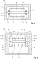
- the Fig. 1 shows in a schematic and simplified flow diagram a method 2 according to the invention for producing a battery cell 4 ( Fig. 2 ).
- the following, based on the Figures 2 to 5 The method described in this embodiment comprises, for example, nine consecutive method steps OP1, ..., OP9.
- a device (not further specified) for carrying out method 2 or method steps OP1, ..., OP9 is also described below with reference to the Figures 2 to 5 explained in more detail.
- the battery cell 4 has an electrode or cell stack 6 with a number of thin-film cells stacked one above the other, each having a cathode layer and an anode layer, as well as a separator layer (separator) inserted therebetween.
- an active material or electrode material layer is applied to each Current conductors 8, 10 are applied.
- the current conductors 8, 10 are designed, for example, as metal foils, with copper foils being suitably used for the anode layers and aluminum foils for the cathode layers.
- the current conductors 8, 10 protrude from the edges of the electrode stack 6 as conductor tabs or electrode conductor tabs.
- the current conductors 8 are to be understood as aluminum foils in particular, and the current conductors 10 as copper foils in particular.
- the Fig. 3 shows, in successive representations, process step OP1 of process 2.
- process step OP1 the surface of the current collectors 8, 10 is cleaned using ultrasound. During surface cleaning, oxides, moisture, and oily products are removed from the surface of the current collectors 8, 10.
- the device comprises an ultrasonic cleaner 12 with an ultrasonic bath 14.
- An ultrasonic generator 16 for frequencies up to 40 kHz (kilohertz) is arranged in the ultrasonic bath 14, wherein the ultrasonic bath 14 is filled with a liquid 18.
- the liquid 18 is, for example, distilled water with alkaline solvents or additives for oxide cleaning.
- the ultrasonic generator 16 generates an ultrasonic wave 20, which has the greatest amplitude in the area of the immersed current conductors 8, 10.
- the ultrasonic wave 20 generates rapidly moving cavitation bubbles 22 in the liquid 18, which move at the ultrasonic frequency and remove dirt and oily substances from the surfaces of the current conductors 8, 10.
- the alkaline additives in the liquid 18 help to remove oxides on the surfaces.
- the ultrasonic bath 14 is covered with a lid 24.
- the lid 24 is made of rubber and has slots for guiding the current collectors 8, 10.
- cleaning roller brushes 26 with polyamide fibers are provided for the mechanical cleaning of the current collectors 8, 10. The cleaning roller brushes 26 are moved by contact with the current collectors 8, 10.
- the electrode stack 6 is secured by a gripper 28 in a guide plate 30 for ultrasonic cleaning.
- the electrode stack 6 is lowered by means of the guide plate 30 so that the current collector 8 is immersed through the slotted cover 24 into the ultrasonic bath 14 and is cleaned by the cavitation bubbles 22 and the cleaning roller brushes 26.
- the electrode stack 6 is then moved vertically upwards by means of a gripper 32 and pivoted by 180° by means of a joint 34.
- the current collector 10 is then immersed in the ultrasonic bath 14 and cleaned.
- the electrode stack 6 is enclosed in a protective cover. 36 so that as little liquid 18 as possible reaches the electrode stack 6.
- the electrode stack 6 is removed from the guide plate 30 by a gripper 38 and guided to the process step OP2.
- stamps are made, in particular, of graphite, titanium, or tungsten.
- the device has a heating chamber as a housing 40.
- the heating chamber 40 has a gas 42 inside it.
- the inert gas 42 is embodied as nitrogen, for example, and is introduced into the heating chamber 40 under an overpressure of, for example, 15 mbar (millibars).
- Two cooling plates 44 are provided to prevent undesired heating of the electrode stack 6.
- the cooling plates 44 are pressed against the electrode stack 6 on both sides by means of a gripper 46 with a clamping force shown as arrows, so that the electrode stack 6 is tempered to a maximum temperature of 50 °C during preheating.
- the cooling plates 44 are cooled by a water and glycol suspension, with the temperature being adjusted or regulated based on the water cooling rate.
- the current collectors 8, 10 are each preheated by means of a heating device 48.
- the heating device 48 heats the current collectors 8, 10, for example, via induction or via an electrical (heating) resistor.
- the current conductors 8, 10 are pressed in the process step OP3 within the heating chamber 40 with a heated stamping device 50, 52 ( Fig. 5 ).
- the stamping devices 50, 52 each have a movable (pressure) stamp 54 and a fixed stamp 56 as a counter bearing.
- the stamps 56 are supported on a base plate 58. Both the fixed and the movable stamp 54, 56 are heated by heating cartridges 60 embedded in a ceramic cover or a ceramic jacket.
- the plungers 54, 56 are made of graphite for low pressures, for example, and of carbide and/or titanium for high pressures.
- the stamp 54 of the stamping device 50 is heated in particular to a temperature between 350°C and 600°C, for example up to 400°C, and generates a pressure of, for example, 4 bar to 6 bar on the current conductors 8.
- the stamp 54 of the stamping device 52 is heated in particular to a temperature between 550°C and 750°C, for example up to 700°C, and generates a pressure of, for example, 6 bar to 7 bar on the current conductors 10.
- the temperature is preferably 500°C to 700°C, although higher pressure is required at lower temperatures.
- the punches 54 are designed, for example, as pneumatic cylinders, which generate the necessary force for welding.
- the punch 54 or pneumatic cylinder requires approximately 4 bar of air pressure for welding copper at 700°C.
- approximately 6 bar of air pressure is required. This means that in this temperature range, normal industrial air pressure is sufficient for pressure welding.
- a temperature range of 400 to 600°C is preferably used. At 400°C, approximately 6 bar of air pressure is required in the pneumatic cylinder, whereas at 600°C, approximately 4 bar of air pressure is required.
- the air pressure of the pneumatic cylinders or pistons 54 also depends on the piston surface of the pneumatic cylinder. Larger pneumatic cylinder pistons require less air pressure.
- the temperature of the stamps 54 is always lower than the melting temperature of the respective current conductor material.
- the stamping devices 50, 52 join the current conductors 8 to form a common cathode 62, and the stamping device 52 joins the current conductors 10 to form a common anode 64 without melting.
- pressure welding is performed, with the force 65 required for pressure welding being calculated using the following formula: Surface of the collector * Yield stress (approx. 50 MPa) * Factor (5 to 10)
- the current conductors 8, 10 are heated to a temperature such that the yield stress is approximately the same, whereby the current conductors 8, 10 can be pressure welded with essentially the same stamping pressure.
- the yield stress is approximately 50 MPa.
- Welding results in a thickness deformation of approximately 2%.
- the force required for welding is the yield stress times the weld area times the correction factor.
- the correction factor is typically 3 to 5, depending on the surface condition. Since aluminum oxide is difficult to weld, the welding temperature for aluminum can be increased to 600°C.
- Pressure welding is also performed under the inert nitrogen atmosphere of gas 42.
- the electrode stack 6 is cooled to below 50°C by the cooling plates, as in process step OP2. During pressure welding, the collectors 62, 64 are held under the heated dies 54, 56 for three to five seconds.
- the material of the collectors 62, 64 deforms by a maximum of 5%. Due to the shear deformation, the remaining oxide layer breaks open, and atomic contact occurs between the connecting metals. The material is welded using the solid-state diffusion process. It is important that the material is not melted during this welding process, and therefore no intermetallic compounds form in the collectors 62, 64.
- the joined collectors 62, 64 are also trimmed after the pressure welding is completed.
- Fig. 5 The trimming shown for the anode 64 is performed in the same stroke as pressure welding, with the collector dimensions within tolerance limits. Since trimming occurs at a higher temperature of the joined metal, less cutting force is advantageously required.
- the punch 54 has an integrated cutting punch 66 for separating or trimming the anode 64.
- the cutting punch 66 is coupled to a pneumatic system with a spring piston 68 and a spring cylinder head 70, wherein the spring cylinder head 70 is mounted with the punch 54 on a press ram 72.
- the punch 56 is designed with a cutting die 74 as a counterbearing for the cutting punch 66, which is provided with a waste chute 76 for the separated material.
- an optional process step OP4 is performed.
- a protective coating is applied to the anode 64 as corrosion protection.
- This optional process step OP4 improves conductivity and provides galvanic corrosion protection for the anode 64.
- the anode or copper collector 64 is immersed in a molten tin bath.
- a nickel coating for example, is also conceivable.
- process step OP6 for example, a deep-drawing process is carried out, with which an aluminum composite foil is deep-drawn into the housing half, wherein in process step OP7, in particular the provided pre-sealing tapes 76, 78 are pre-fixed on the housing half.
- the electrode stack 6 is inserted between two housing halves equipped with pre-sealing strips 106, 108.
- the housing halves are then brought into contact in the region of edge flanges and joined or sealed to form a cell housing 80 using a heat-sealing process.
- the electrode stack 6 is completely accommodated in the cell housing 80, with only the anode 64 and the cathode 62 protruding from the cell housing 80.
- the electrode stack 6 is arranged essentially in one half of the cell housing 80, with the other half acting as a free space or gas pocket 82 to absorb gases generated during operation as a buffer volume.
- the welding is carried out in particular by electromagnetic pulse welding (EMP welding).
- EMP welding electromagnetic pulse welding
- an external movement device which is moved at high speed and creates a weld between the pre-sealing band 78 and the collector 64 by impact.
- the external device is operated by induced Magnetic fields are used.
- EMP welding ultrasonic welding is also possible.
- Ultrasonic welding can also join polypropylene. Using ultrasonic welding, the heat-sealing process can be avoided. Ultrasonic welding joins the housing halves to each other and to the plastic layers, as well as the metal layers of the pre-sealing bands 76, 78 and the collectors 62, 64. It is important that the strength of the weld be tested under vibration load after ultrasonic welding.
- process steps OP8 and OP9 are interchangeable.
- the order of OP8 and OP9 can be reversed, and first, an EMP welding process can be performed to firmly bond the pre-sealing strips 76, 78 to the collectors 62, 64, followed by a heat-sealing process to firmly bond the housing halves.
- this is preferably filled into the gas pocket 82 during process step OP8 or OP9 before the cell housing 80 is completely closed and sealed in the area of the collector.
Landscapes
- Engineering & Computer Science (AREA)
- Chemical & Material Sciences (AREA)
- Chemical Kinetics & Catalysis (AREA)
- Electrochemistry (AREA)
- General Chemical & Material Sciences (AREA)
- Manufacturing & Machinery (AREA)
- Mechanical Engineering (AREA)
- Materials Engineering (AREA)
- Connection Of Batteries Or Terminals (AREA)
Claims (9)
- Procédé (2) permettant de fabriquer une cellule de batterie (4), présentant un empilement d'électrodes (6) pourvu d'un certain nombre de premiers et deuxièmes conducteurs (8, 10) qui sont disposés en couches les uns au-dessus des autres,- dans lequel les premiers conducteurs (8) sont assemblés en une cathode commune (62) et les deuxièmes conducteurs (10) sont assemblés en une anode commune (64) par liaison de matière sans fusion au moyen d'un soudage par pression à chaud,- dans lequel les premiers et deuxièmes conducteurs (8, 10) sont chauffés avant l'assemblage, et- dans lequel l'empilement d'électrodes (6) est refroidi pendant le préchauffage et pendant l'opération d'assemblage.
- Procédé (2) selon la revendication 1,
caractérisé
en ce que les premiers et deuxièmes conducteurs (8, 10) sont disposés en au moins dix couches, en particulier en plus de 20 couches, de préférence entre 30 et 50 couches. - Procédé (2) selon la revendication 1 ou 2,
caractérisé
en ce que les premiers et deuxièmes conducteurs (8, 10) sont nettoyés avant l'assemblage. - Procédé (2) selon la revendication 3,
caractérisé
en ce que les premiers et deuxièmes conducteurs (8, 10) sont nettoyés dans un bain à ultrasons (14). - Procédé (2) selon l'une quelconque des revendications 1 à 4,
caractérisé
en ce que les premiers et deuxièmes conducteurs (8, 10) sont nettoyés par induction avant l'assemblage. - Procédé (2) selon l'une quelconque des revendications 1 à 5,
caractérisé
en ce que le soudage par pression à chaud est effectué dans une atmosphère d'azote. - Dispositif permettant d'exécuter un procédé (2) selon l'une quelconque des revendications 1 à 6, présentant- un boîtier (40),- un dispositif de poinçonnage (50, 52) reçu dans le boîtier (40), comprenant respectivement un poinçon de pression supérieur (54) et un poinçon de pression inférieur (56) pour le soudage par pression à chaud des premiers et des deuxièmes conducteurs (8, 10),- un dispositif de chauffage (48) pour le préchauffage des premiers et deuxièmes conducteurs (8, 10), et- un dispositif de refroidissement (44) pour refroidir l'empilement d'électrodes (6).
- Dispositif selon la revendication 7,
caractérisé
en ce qu'un poinçon d'ébavurage pneumatique (66) est intégré dans le poinçon de pression (54) pour découper la cathode (62) et l'anode (64). - Cellule de batterie (4), en particulier cellule de poche, présentant un empilement d'électrodes (6) pourvu d'un certain nombre de premiers et deuxièmes conducteurs (8, 10), et un boîtier de cellule (80) recevant l'empilement d'électrodes (6), dans lequel les premiers conducteurs (8) sont assemblés en une cathode commune (62) et les deuxièmes conducteurs (10) sont assemblés en une anode commune (64) au moyen d'un soudage par pression à chaud.
Applications Claiming Priority (1)
| Application Number | Priority Date | Filing Date | Title |
|---|---|---|---|
| DE102020214832.5A DE102020214832A1 (de) | 2020-11-25 | 2020-11-25 | Verfahren zur Herstellung einer Batteriezelle |
Publications (2)
| Publication Number | Publication Date |
|---|---|
| EP4007025A1 EP4007025A1 (fr) | 2022-06-01 |
| EP4007025B1 true EP4007025B1 (fr) | 2025-04-23 |
Family
ID=78414375
Family Applications (1)
| Application Number | Title | Priority Date | Filing Date |
|---|---|---|---|
| EP21205295.5A Active EP4007025B1 (fr) | 2020-11-25 | 2021-10-28 | Procédé de fabrication d'un élément de batterie |
Country Status (3)
| Country | Link |
|---|---|
| EP (1) | EP4007025B1 (fr) |
| CN (1) | CN114614099B (fr) |
| DE (1) | DE102020214832A1 (fr) |
Families Citing this family (4)
| Publication number | Priority date | Publication date | Assignee | Title |
|---|---|---|---|---|
| CN116423030B (zh) * | 2023-06-15 | 2023-08-18 | 镭神技术(深圳)有限公司 | 接枝辅焊机构及超声波焊接机 |
| CN117219883B (zh) * | 2023-11-03 | 2024-01-23 | 惠州市汇恒自动化科技有限公司 | 一种锂电池电芯制造加工装置及其加工方法 |
| CN120613422A (zh) * | 2024-03-08 | 2025-09-09 | 通用汽车环球科技运作有限责任公司 | 使用热压固结多层箔的方法 |
| CN118748266B (zh) * | 2024-06-17 | 2025-07-25 | 合肥国轩高科动力能源有限公司 | 一种电极组件加工装置、方法及电极组件 |
Family Cites Families (9)
| Publication number | Priority date | Publication date | Assignee | Title |
|---|---|---|---|---|
| JP4720172B2 (ja) * | 2004-12-10 | 2011-07-13 | ソニー株式会社 | 電池 |
| KR101360665B1 (ko) | 2013-04-17 | 2014-02-10 | 선박안전기술공단 | 유도 가열 방식의 다중 금속 박판 접합 장치 및 방법과 이를 이용한 배터리 전극 탭 접합 장치 및 방법 |
| CN103331511B (zh) * | 2013-07-03 | 2014-07-02 | 林青云 | 电阻焊方法及其应用和所用的电极焊头 |
| DE102014226806B3 (de) | 2014-09-22 | 2015-12-17 | Fraunhofer-Gesellschaft zur Förderung der angewandten Forschung e.V. | Verfahren zur Herstellung elektrisch leitender Verbindungen, von mindestens zwei stoffschlüssig miteinander verbundenen Fügepartnern |
| KR20200053463A (ko) * | 2017-06-15 | 2020-05-18 | 에이일이삼 시스템즈, 엘엘씨 | 전기화학적 셀을 위한 적층된 각기둥형 아키텍처 |
| DE102018203052A1 (de) * | 2018-03-01 | 2019-09-05 | Gs Yuasa International Ltd. | Batterie und Verfahren zum Herstellen einer Batterie |
| JP7021564B2 (ja) | 2018-03-02 | 2022-02-17 | 三洋電機株式会社 | 二次電池及びその製造方法 |
| US20190296316A1 (en) * | 2018-03-26 | 2019-09-26 | GM Global Technology Operations LLC | Battery tab having a localized welded joint and method of making the same |
| US20190363328A1 (en) * | 2018-05-22 | 2019-11-28 | GM Global Technology Operations LLC | Robust Reaction Metallurgical Joining |
-
2020
- 2020-11-25 DE DE102020214832.5A patent/DE102020214832A1/de active Pending
-
2021
- 2021-10-28 EP EP21205295.5A patent/EP4007025B1/fr active Active
- 2021-11-25 CN CN202111410567.2A patent/CN114614099B/zh active Active
Also Published As
| Publication number | Publication date |
|---|---|
| CN114614099A (zh) | 2022-06-10 |
| EP4007025A1 (fr) | 2022-06-01 |
| DE102020214832A1 (de) | 2022-05-25 |
| CN114614099B (zh) | 2025-02-28 |
Similar Documents
| Publication | Publication Date | Title |
|---|---|---|
| EP4007025B1 (fr) | Procédé de fabrication d'un élément de batterie | |
| EP2740168B1 (fr) | Élément individuel pour une batterie | |
| DE102008059949B4 (de) | Batterie, Verfahren zur Herstellung einer Batterie und Verwendung der Batterie | |
| EP3080854A1 (fr) | Procédé pour entretenir, réparer et/ou optimiser une batterie et batterie dotée d'un certain nombre d'éléments individuels interconnectés électriquement | |
| EP1826850A2 (fr) | Procédé d'assemblage de plaques bipolaires, en particulier pour un empilement de piles à combustible d'un véhicule automobile | |
| EP4117066B1 (fr) | Procédé et dispositif de fabrication d'un composant pour un élément de batterie, ainsi que composant | |
| EP1779962A1 (fr) | Méthode de soudure de fines plaques de différents métaux, corps jointif de fines plaques de différents métaux, le dispositif électrique et le montage électrique du dispositif | |
| DE102020213462A1 (de) | Verfahren zur Herstellung einer Batteriezelle | |
| DE102020120263B3 (de) | Verschweißen von metallischen Folien mittels Laser | |
| DE102011110694A1 (de) | Gehäusedeckel für einen elektrochemischen Energiespeicher mit einem becherförmigen Gehäuse und Verfahren zur Herstellung des Gehäusedeckels | |
| DE102012018041A1 (de) | Isolation von elektrochemischen Energiespeichern | |
| DE102010055615A1 (de) | Einzelzelle für eine Batterie und Verfahren zur Herstellung einer solchen Einzelzelle | |
| DE102009035490A1 (de) | Elektrodenanordnung für eine Batterieeinzelzelle | |
| DE102018006718A1 (de) | Batteriezelle und Verfahren zur Herstellung einer Batteriezelle | |
| DE102022124854A1 (de) | Metall-polymer-hybrid-stromkollektor für eine batterieelektrode und verfahren zu deren herstellung | |
| EP2243179B1 (fr) | Procédé de fabrication d'une cellule individuelle pour batterie | |
| DE102022126390B4 (de) | Verfahren zum biegen und schlagschweissen mehrerer gebogener metallfolien einer batterie | |
| DE102010050046A1 (de) | Elektrochemiche Zelle und Verfahren zu deren Herstellung | |
| EP4414115A2 (fr) | Cellule de batterie | |
| DE102008059963A1 (de) | Einzelzelle für eine Batterie und Verfahren zu deren Herstellung | |
| WO2014040733A1 (fr) | Procédé pour remplir une cellule électrochimique individuelle avec une substance électrochimique active et pour refermer la cellule électrochimique individuelle | |
| DE102020216311A1 (de) | Verfahren zur Herstellung einer Beutelhälfte einer Pouchzelle | |
| DE102022120549A1 (de) | Batterie mit einem Gehäuse und einer elektrisch isolierenden Umhüllung | |
| DE102023004059A1 (de) | Verfahren zur Herstellung einer elektrischen Kontaktierung metallischer Folien, Folienstapel und elektrischer Energiespeicher | |
| DE102022003829A1 (de) | Verfahren und Vorrichtung zum Fügen und elektrischen Kontaktieren von Folienstapeln |
Legal Events
| Date | Code | Title | Description |
|---|---|---|---|
| PUAI | Public reference made under article 153(3) epc to a published international application that has entered the european phase |
Free format text: ORIGINAL CODE: 0009012 |
|
| STAA | Information on the status of an ep patent application or granted ep patent |
Free format text: STATUS: THE APPLICATION HAS BEEN PUBLISHED |
|
| AK | Designated contracting states |
Kind code of ref document: A1 Designated state(s): AL AT BE BG CH CY CZ DE DK EE ES FI FR GB GR HR HU IE IS IT LI LT LU LV MC MK MT NL NO PL PT RO RS SE SI SK SM TR |
|
| STAA | Information on the status of an ep patent application or granted ep patent |
Free format text: STATUS: REQUEST FOR EXAMINATION WAS MADE |
|
| 17P | Request for examination filed |
Effective date: 20221201 |
|
| RBV | Designated contracting states (corrected) |
Designated state(s): AL AT BE BG CH CY CZ DE DK EE ES FI FR GB GR HR HU IE IS IT LI LT LU LV MC MK MT NL NO PL PT RO RS SE SI SK SM TR |
|
| GRAP | Despatch of communication of intention to grant a patent |
Free format text: ORIGINAL CODE: EPIDOSNIGR1 |
|
| STAA | Information on the status of an ep patent application or granted ep patent |
Free format text: STATUS: GRANT OF PATENT IS INTENDED |
|
| RIC1 | Information provided on ipc code assigned before grant |
Ipc: H01M 10/04 20060101AFI20241204BHEP |
|
| INTG | Intention to grant announced |
Effective date: 20241213 |
|
| GRAS | Grant fee paid |
Free format text: ORIGINAL CODE: EPIDOSNIGR3 |
|
| GRAA | (expected) grant |
Free format text: ORIGINAL CODE: 0009210 |
|
| STAA | Information on the status of an ep patent application or granted ep patent |
Free format text: STATUS: THE PATENT HAS BEEN GRANTED |
|
| RAP1 | Party data changed (applicant data changed or rights of an application transferred) |
Owner name: POWERCO SE |
|
| AK | Designated contracting states |
Kind code of ref document: B1 Designated state(s): AL AT BE BG CH CY CZ DE DK EE ES FI FR GB GR HR HU IE IS IT LI LT LU LV MC MK MT NL NO PL PT RO RS SE SI SK SM TR |
|
| REG | Reference to a national code |
Ref country code: GB Ref legal event code: FG4D Free format text: NOT ENGLISH |
|
| REG | Reference to a national code |
Ref country code: CH Ref legal event code: EP |
|
| REG | Reference to a national code |
Ref country code: DE Ref legal event code: R096 Ref document number: 502021007275 Country of ref document: DE |
|
| REG | Reference to a national code |
Ref country code: IE Ref legal event code: FG4D Free format text: LANGUAGE OF EP DOCUMENT: GERMAN |
|
| REG | Reference to a national code |
Ref country code: NL Ref legal event code: MP Effective date: 20250423 |
|
| PG25 | Lapsed in a contracting state [announced via postgrant information from national office to epo] |
Ref country code: NL Free format text: LAPSE BECAUSE OF FAILURE TO SUBMIT A TRANSLATION OF THE DESCRIPTION OR TO PAY THE FEE WITHIN THE PRESCRIBED TIME-LIMIT Effective date: 20250423 |
|
| PG25 | Lapsed in a contracting state [announced via postgrant information from national office to epo] |
Ref country code: ES Free format text: LAPSE BECAUSE OF FAILURE TO SUBMIT A TRANSLATION OF THE DESCRIPTION OR TO PAY THE FEE WITHIN THE PRESCRIBED TIME-LIMIT Effective date: 20250423 Ref country code: PT Free format text: LAPSE BECAUSE OF FAILURE TO SUBMIT A TRANSLATION OF THE DESCRIPTION OR TO PAY THE FEE WITHIN THE PRESCRIBED TIME-LIMIT Effective date: 20250825 Ref country code: FI Free format text: LAPSE BECAUSE OF FAILURE TO SUBMIT A TRANSLATION OF THE DESCRIPTION OR TO PAY THE FEE WITHIN THE PRESCRIBED TIME-LIMIT Effective date: 20250423 |
|
| REG | Reference to a national code |
Ref country code: LT Ref legal event code: MG9D |
|
| PG25 | Lapsed in a contracting state [announced via postgrant information from national office to epo] |
Ref country code: NO Free format text: LAPSE BECAUSE OF FAILURE TO SUBMIT A TRANSLATION OF THE DESCRIPTION OR TO PAY THE FEE WITHIN THE PRESCRIBED TIME-LIMIT Effective date: 20250723 Ref country code: GR Free format text: LAPSE BECAUSE OF FAILURE TO SUBMIT A TRANSLATION OF THE DESCRIPTION OR TO PAY THE FEE WITHIN THE PRESCRIBED TIME-LIMIT Effective date: 20250724 |
|
| PG25 | Lapsed in a contracting state [announced via postgrant information from national office to epo] |
Ref country code: PL Free format text: LAPSE BECAUSE OF FAILURE TO SUBMIT A TRANSLATION OF THE DESCRIPTION OR TO PAY THE FEE WITHIN THE PRESCRIBED TIME-LIMIT Effective date: 20250423 |
|
| PG25 | Lapsed in a contracting state [announced via postgrant information from national office to epo] |
Ref country code: BG Free format text: LAPSE BECAUSE OF FAILURE TO SUBMIT A TRANSLATION OF THE DESCRIPTION OR TO PAY THE FEE WITHIN THE PRESCRIBED TIME-LIMIT Effective date: 20250423 |
|
| PG25 | Lapsed in a contracting state [announced via postgrant information from national office to epo] |
Ref country code: HR Free format text: LAPSE BECAUSE OF FAILURE TO SUBMIT A TRANSLATION OF THE DESCRIPTION OR TO PAY THE FEE WITHIN THE PRESCRIBED TIME-LIMIT Effective date: 20250423 |
|
| PG25 | Lapsed in a contracting state [announced via postgrant information from national office to epo] |
Ref country code: RS Free format text: LAPSE BECAUSE OF FAILURE TO SUBMIT A TRANSLATION OF THE DESCRIPTION OR TO PAY THE FEE WITHIN THE PRESCRIBED TIME-LIMIT Effective date: 20250723 |
|
| PG25 | Lapsed in a contracting state [announced via postgrant information from national office to epo] |
Ref country code: IS Free format text: LAPSE BECAUSE OF FAILURE TO SUBMIT A TRANSLATION OF THE DESCRIPTION OR TO PAY THE FEE WITHIN THE PRESCRIBED TIME-LIMIT Effective date: 20250823 |
|
| PG25 | Lapsed in a contracting state [announced via postgrant information from national office to epo] |
Ref country code: LV Free format text: LAPSE BECAUSE OF FAILURE TO SUBMIT A TRANSLATION OF THE DESCRIPTION OR TO PAY THE FEE WITHIN THE PRESCRIBED TIME-LIMIT Effective date: 20250423 |
|
| PGFP | Annual fee paid to national office [announced via postgrant information from national office to epo] |
Ref country code: DE Payment date: 20251031 Year of fee payment: 5 |
|
| PG25 | Lapsed in a contracting state [announced via postgrant information from national office to epo] |
Ref country code: SM Free format text: LAPSE BECAUSE OF FAILURE TO SUBMIT A TRANSLATION OF THE DESCRIPTION OR TO PAY THE FEE WITHIN THE PRESCRIBED TIME-LIMIT Effective date: 20250423 Ref country code: DK Free format text: LAPSE BECAUSE OF FAILURE TO SUBMIT A TRANSLATION OF THE DESCRIPTION OR TO PAY THE FEE WITHIN THE PRESCRIBED TIME-LIMIT Effective date: 20250423 |
|
| PGFP | Annual fee paid to national office [announced via postgrant information from national office to epo] |
Ref country code: AT Payment date: 20260113 Year of fee payment: 5 |
|
| PG25 | Lapsed in a contracting state [announced via postgrant information from national office to epo] |
Ref country code: CZ Free format text: LAPSE BECAUSE OF FAILURE TO SUBMIT A TRANSLATION OF THE DESCRIPTION OR TO PAY THE FEE WITHIN THE PRESCRIBED TIME-LIMIT Effective date: 20250423 |
|
| PG25 | Lapsed in a contracting state [announced via postgrant information from national office to epo] |
Ref country code: EE Free format text: LAPSE BECAUSE OF FAILURE TO SUBMIT A TRANSLATION OF THE DESCRIPTION OR TO PAY THE FEE WITHIN THE PRESCRIBED TIME-LIMIT Effective date: 20250423 |
|
| REG | Reference to a national code |
Ref country code: DE Ref legal event code: R097 Ref document number: 502021007275 Country of ref document: DE |
|
| PG25 | Lapsed in a contracting state [announced via postgrant information from national office to epo] |
Ref country code: RO Free format text: LAPSE BECAUSE OF FAILURE TO SUBMIT A TRANSLATION OF THE DESCRIPTION OR TO PAY THE FEE WITHIN THE PRESCRIBED TIME-LIMIT Effective date: 20250423 Ref country code: SK Free format text: LAPSE BECAUSE OF FAILURE TO SUBMIT A TRANSLATION OF THE DESCRIPTION OR TO PAY THE FEE WITHIN THE PRESCRIBED TIME-LIMIT Effective date: 20250423 |
|
| PG25 | Lapsed in a contracting state [announced via postgrant information from national office to epo] |
Ref country code: IT Free format text: LAPSE BECAUSE OF FAILURE TO SUBMIT A TRANSLATION OF THE DESCRIPTION OR TO PAY THE FEE WITHIN THE PRESCRIBED TIME-LIMIT Effective date: 20250423 |
|
| PLBE | No opposition filed within time limit |
Free format text: ORIGINAL CODE: 0009261 |
|
| STAA | Information on the status of an ep patent application or granted ep patent |
Free format text: STATUS: NO OPPOSITION FILED WITHIN TIME LIMIT |
|
| REG | Reference to a national code |
Ref country code: CH Ref legal event code: L10 Free format text: ST27 STATUS EVENT CODE: U-0-0-L10-L00 (AS PROVIDED BY THE NATIONAL OFFICE) Effective date: 20260304 |
|
| 26N | No opposition filed |
Effective date: 20260126 |