EP4007036A1 - Separator für elektrochemische vorrichtung mit einer wärmebeständigen schicht und diese enthaltende sekundärbatterie - Google Patents
Separator für elektrochemische vorrichtung mit einer wärmebeständigen schicht und diese enthaltende sekundärbatterie Download PDFInfo
- Publication number
- EP4007036A1 EP4007036A1 EP20855025.1A EP20855025A EP4007036A1 EP 4007036 A1 EP4007036 A1 EP 4007036A1 EP 20855025 A EP20855025 A EP 20855025A EP 4007036 A1 EP4007036 A1 EP 4007036A1
- Authority
- EP
- European Patent Office
- Prior art keywords
- separator
- electrochemical device
- manufacturing
- resistant layer
- heat resistant
- Prior art date
- Legal status (The legal status is an assumption and is not a legal conclusion. Google has not performed a legal analysis and makes no representation as to the accuracy of the status listed.)
- Pending
Links
Images

Classifications
-
- H—ELECTRICITY
- H01—ELECTRIC ELEMENTS
- H01M—PROCESSES OR MEANS, e.g. BATTERIES, FOR THE DIRECT CONVERSION OF CHEMICAL ENERGY INTO ELECTRICAL ENERGY
- H01M10/00—Secondary cells; Manufacture thereof
- H01M10/05—Accumulators with non-aqueous electrolyte
- H01M10/052—Li-accumulators
-
- H—ELECTRICITY
- H01—ELECTRIC ELEMENTS
- H01M—PROCESSES OR MEANS, e.g. BATTERIES, FOR THE DIRECT CONVERSION OF CHEMICAL ENERGY INTO ELECTRICAL ENERGY
- H01M50/00—Constructional details or processes of manufacture of the non-active parts of electrochemical cells other than fuel cells, e.g. hybrid cells
- H01M50/40—Separators; Membranes; Diaphragms; Spacing elements inside cells
- H01M50/409—Separators, membranes or diaphragms characterised by the material
- H01M50/446—Composite material consisting of a mixture of organic and inorganic materials
-
- H—ELECTRICITY
- H01—ELECTRIC ELEMENTS
- H01M—PROCESSES OR MEANS, e.g. BATTERIES, FOR THE DIRECT CONVERSION OF CHEMICAL ENERGY INTO ELECTRICAL ENERGY
- H01M10/00—Secondary cells; Manufacture thereof
- H01M10/05—Accumulators with non-aqueous electrolyte
- H01M10/052—Li-accumulators
- H01M10/0525—Rocking-chair batteries, i.e. batteries with lithium insertion or intercalation in both electrodes; Lithium-ion batteries
-
- H—ELECTRICITY
- H01—ELECTRIC ELEMENTS
- H01M—PROCESSES OR MEANS, e.g. BATTERIES, FOR THE DIRECT CONVERSION OF CHEMICAL ENERGY INTO ELECTRICAL ENERGY
- H01M10/00—Secondary cells; Manufacture thereof
- H01M10/42—Methods or arrangements for servicing or maintenance of secondary cells or secondary half-cells
- H01M10/4235—Safety or regulating additives or arrangements in electrodes, separators or electrolyte
-
- H—ELECTRICITY
- H01—ELECTRIC ELEMENTS
- H01M—PROCESSES OR MEANS, e.g. BATTERIES, FOR THE DIRECT CONVERSION OF CHEMICAL ENERGY INTO ELECTRICAL ENERGY
- H01M50/00—Constructional details or processes of manufacture of the non-active parts of electrochemical cells other than fuel cells, e.g. hybrid cells
- H01M50/40—Separators; Membranes; Diaphragms; Spacing elements inside cells
- H01M50/403—Manufacturing processes of separators, membranes or diaphragms
-
- H—ELECTRICITY
- H01—ELECTRIC ELEMENTS
- H01M—PROCESSES OR MEANS, e.g. BATTERIES, FOR THE DIRECT CONVERSION OF CHEMICAL ENERGY INTO ELECTRICAL ENERGY
- H01M50/00—Constructional details or processes of manufacture of the non-active parts of electrochemical cells other than fuel cells, e.g. hybrid cells
- H01M50/40—Separators; Membranes; Diaphragms; Spacing elements inside cells
- H01M50/409—Separators, membranes or diaphragms characterised by the material
- H01M50/411—Organic material
-
- H—ELECTRICITY
- H01—ELECTRIC ELEMENTS
- H01M—PROCESSES OR MEANS, e.g. BATTERIES, FOR THE DIRECT CONVERSION OF CHEMICAL ENERGY INTO ELECTRICAL ENERGY
- H01M50/00—Constructional details or processes of manufacture of the non-active parts of electrochemical cells other than fuel cells, e.g. hybrid cells
- H01M50/40—Separators; Membranes; Diaphragms; Spacing elements inside cells
- H01M50/409—Separators, membranes or diaphragms characterised by the material
- H01M50/411—Organic material
- H01M50/414—Synthetic resins, e.g. thermoplastics or thermosetting resins
- H01M50/426—Fluorocarbon polymers
-
- H—ELECTRICITY
- H01—ELECTRIC ELEMENTS
- H01M—PROCESSES OR MEANS, e.g. BATTERIES, FOR THE DIRECT CONVERSION OF CHEMICAL ENERGY INTO ELECTRICAL ENERGY
- H01M50/00—Constructional details or processes of manufacture of the non-active parts of electrochemical cells other than fuel cells, e.g. hybrid cells
- H01M50/40—Separators; Membranes; Diaphragms; Spacing elements inside cells
- H01M50/409—Separators, membranes or diaphragms characterised by the material
- H01M50/431—Inorganic material
- H01M50/434—Ceramics
-
- H—ELECTRICITY
- H01—ELECTRIC ELEMENTS
- H01M—PROCESSES OR MEANS, e.g. BATTERIES, FOR THE DIRECT CONVERSION OF CHEMICAL ENERGY INTO ELECTRICAL ENERGY
- H01M50/00—Constructional details or processes of manufacture of the non-active parts of electrochemical cells other than fuel cells, e.g. hybrid cells
- H01M50/40—Separators; Membranes; Diaphragms; Spacing elements inside cells
- H01M50/409—Separators, membranes or diaphragms characterised by the material
- H01M50/449—Separators, membranes or diaphragms characterised by the material having a layered structure
-
- H—ELECTRICITY
- H01—ELECTRIC ELEMENTS
- H01M—PROCESSES OR MEANS, e.g. BATTERIES, FOR THE DIRECT CONVERSION OF CHEMICAL ENERGY INTO ELECTRICAL ENERGY
- H01M50/00—Constructional details or processes of manufacture of the non-active parts of electrochemical cells other than fuel cells, e.g. hybrid cells
- H01M50/40—Separators; Membranes; Diaphragms; Spacing elements inside cells
- H01M50/489—Separators, membranes, diaphragms or spacing elements inside the cells, characterised by their physical properties, e.g. swelling degree, hydrophilicity or shut down properties
-
- H—ELECTRICITY
- H01—ELECTRIC ELEMENTS
- H01M—PROCESSES OR MEANS, e.g. BATTERIES, FOR THE DIRECT CONVERSION OF CHEMICAL ENERGY INTO ELECTRICAL ENERGY
- H01M50/00—Constructional details or processes of manufacture of the non-active parts of electrochemical cells other than fuel cells, e.g. hybrid cells
- H01M50/40—Separators; Membranes; Diaphragms; Spacing elements inside cells
- H01M50/489—Separators, membranes, diaphragms or spacing elements inside the cells, characterised by their physical properties, e.g. swelling degree, hydrophilicity or shut down properties
- H01M50/491—Porosity
-
- Y—GENERAL TAGGING OF NEW TECHNOLOGICAL DEVELOPMENTS; GENERAL TAGGING OF CROSS-SECTIONAL TECHNOLOGIES SPANNING OVER SEVERAL SECTIONS OF THE IPC; TECHNICAL SUBJECTS COVERED BY FORMER USPC CROSS-REFERENCE ART COLLECTIONS [XRACs] AND DIGESTS
- Y02—TECHNOLOGIES OR APPLICATIONS FOR MITIGATION OR ADAPTATION AGAINST CLIMATE CHANGE
- Y02E—REDUCTION OF GREENHOUSE GAS [GHG] EMISSIONS, RELATED TO ENERGY GENERATION, TRANSMISSION OR DISTRIBUTION
- Y02E60/00—Enabling technologies; Technologies with a potential or indirect contribution to GHG emissions mitigation
- Y02E60/10—Energy storage using batteries
-
- Y—GENERAL TAGGING OF NEW TECHNOLOGICAL DEVELOPMENTS; GENERAL TAGGING OF CROSS-SECTIONAL TECHNOLOGIES SPANNING OVER SEVERAL SECTIONS OF THE IPC; TECHNICAL SUBJECTS COVERED BY FORMER USPC CROSS-REFERENCE ART COLLECTIONS [XRACs] AND DIGESTS
- Y02—TECHNOLOGIES OR APPLICATIONS FOR MITIGATION OR ADAPTATION AGAINST CLIMATE CHANGE
- Y02P—CLIMATE CHANGE MITIGATION TECHNOLOGIES IN THE PRODUCTION OR PROCESSING OF GOODS
- Y02P70/00—Climate change mitigation technologies in the production process for final industrial or consumer products
- Y02P70/50—Manufacturing or production processes characterised by the final manufactured product
Definitions
- the present application claims priority to Korean Patent Application No. 10-2019-0100504 filed on August 16, 2019 in the Republic of Korea, the disclosures of which are incorporated herein by reference.
- the present disclosure relates to a separator for an electrochemical device having improved heat resistance and stability.
- the electrochemical device may be a primary battery or a secondary battery, and the secondary battery includes a lithium ion secondary battery.
- lithium secondary batteries developed in the early 1990's have been spotlighted, since they have a higher operating voltage and significantly higher energy density as compared to conventional batteries, such as Ni-MH, Ni-Cd and sulfuric acid-lead batteries using an aqueous electrolyte.
- conventional batteries such as Ni-MH, Ni-Cd and sulfuric acid-lead batteries using an aqueous electrolyte.
- lithium ion batteries have a safety-related problem, such as ignition and explosion, caused by the use of an organic electrolyte and require a complicated manufacturing process undesirably.
- lithium ion polymer batteries have improved the above-mentioned disadvantages of lithium ion batteries, and thus have been regarded as one of the next-generation batteries.
- such lithium ion polymer batteries have relatively lower capacity as compared to lithium ion batteries, and particularly show insufficient discharge capacity at low temperature. Therefore, there is an imminent need for solving the above-mentioned problem.
- electrochemical devices Although such electrochemical devices have been produced from many production companies, safety characteristics thereof show different signs. Evaluation and securement of safety of such electrochemical devices are very important. The most important consideration is that electrochemical devices should not damage users upon their malfunction. For this purpose, safety standards strictly control ignition and smoke emission in electrochemical devices. With regard to safety characteristics of electrochemical devices, there is great concern about explosion when an electrochemical device is overheated to cause thermal runaway or perforation of a separator.
- a polyolefin-based porous polymer substrate used conventionally as a separator for an electrochemical device shows a severe heat shrinking behavior at a temperature of 130°C or higher due to its material property and a characteristic during its manufacturing process, including orientation, thereby causing a short-circuit between a positive electrode and a negative electrode.
- a separator having a porous composite coating layer by coating a mixture of inorganic particles with a binder polymer on at least one surface of a sheet (substrate) for a porous separator.
- the inorganic particles contained in the coating layer have higher heat resistance as compared to polymeric materials. Therefore, an effect of preventing a short-circuit between a positive electrode and a negative electrode was obtained, even when an electrochemical device is overheated, unlike a separator including a substrate using a polymeric material alone.
- the inorganic particles introduced to the coating layer are problematic in that they are not dispersed homogeneously but are agglomerated in the slurry during the preparation of the slurry for forming a coating layer.
- the inorganic particles are precipitated and concentrated at a specific portion in the coating layer, upon drying after the application.
- a method for improving the dispersibility of inorganic particles has been suggested, but there is another problem of degradation of convenience of processing. Therefore, there is a need for a novel method for introducing inorganic particles to a separator.
- the present disclosure is designed to solve the problems of the related art, and therefore the present disclosure is directed to providing a method for manufacturing a separator including a heat resistant layer.
- the method for manufacturing a separator according to the present disclosure is intended to allow inorganic particles to show a homogeneous dispersed phase, while not causing localization in a heat resistant layer or aggregation of particles. It will be easily understood that the objects and advantages of the present disclosure may be realized by the means shown in the appended claims and combinations thereof.
- a method for manufacturing a separator for an electrochemical device including a heat resistant layer, wherein the heat resistant layer is formed by applying slurry containing a ceramic precursor and a binder resin to at least one surface of a support member, followed by drying, and a pore forming process including at least one step selected from a step of allowing the support member coated with the slurry to stand under a humidified condition and a step of dipping the support member coated with the slurry in a non-solvent is carried out, before drying.
- the method for manufacturing a separator for an electrochemical device as defined in the first embodiment wherein the ceramic precursor includes at least one selected from polysilazane, polycarbosilane, polysiloxane, aluminum amide, polyborazine and polytitanium imide.
- the method for manufacturing a separator for an electrochemical device as defined in the first or the second embodiment wherein the ceramic precursor includes polysilazane, and the polysilazane includes at least one compound represented by the following Chemical Formula 1: wherein each of R 1 , R 2 and R 3 independently represents hydrogen, an alkyl group, alkenyl group, cycloalkyl group, aryl group, alkylsilyl group, alkylamino group, alkoxy group or a halogen.
- the method for manufacturing a separator for an electrochemical device as defined in any one of the first to the third embodiments, wherein the binder resin includes a polyvinylidene fluoride-based polymer resin containing vinylidene fluoride as a polymerization unit.
- the method for manufacturing a separator for an electrochemical device as defined in any one of the first to the fourth embodiments, wherein the slurry is prepared by preparing a polymer solution containing a binder resin and a precursor solution containing a ceramic precursor separately, and mixing the solutions with each other.
- the method for manufacturing a separator for an electrochemical device as defined in any one of the first to the fifth embodiments, wherein the polyvinylidene fluoride-based polymer resin has a weight average molecular weight of 300,000-1,500,000.
- the method for manufacturing a separator for an electrochemical device as defined in any one of the first to the sixth embodiments, wherein the polyvinylidene fluoride-based polymer resin includes a copolymer of vinylidene fluoride with a copolymerizable monomer, and the copolymer has a substitution degree with the monomer of 1-30 wt%.
- the method for manufacturing a separator for an electrochemical device as defined in any one of the first to the seventh embodiments, wherein the content of the ceramic precursor in the slurry is 10-85 wt% based on 100 wt% of the combined weight of the ceramic precursor and the binder resin.
- the method for manufacturing a separator for an electrochemical device as defined in any one of the first to the eighth embodiments, wherein the step of allowing the support member coated with the slurry to stand under a humidified condition is carried out under a relative humidity of 30-60%.
- the method for manufacturing a separator for an electrochemical device as defined in any one of the first to the ninth embodiments, wherein the non-solvent includes at least one selected from water, isopropyl alcohol, methyl alcohol and ethyl alcohol.
- the method for manufacturing a separator for an electrochemical device as defined in any one of the first to the tenth embodiments wherein the separator is further subjected to an additional step, such as a UV irradiation step and/or a plasma treatment step, after drying.
- a separator for an electrochemical device including a heat resistant layer, wherein the heat resistant layer includes a mixture of a ceramic material with a binder resin, the ceramic material is derived from a ceramic precursor, and the ceramic precursor includes polysilazane.
- the method for manufacturing a separator according to the present disclosure shows high convenience of processing, since the ceramic precursor can be converted into an inorganic material at a temperature lower than the melting point of the binder.
- the separator obtained by the method for manufacturing a separator according to the present disclosure includes a heat resistant layer in which inorganic particles are not localized, locally distributed or agglomerated and the ceramic material converted from the ceramic precursor is distributed homogeneously throughout the whole heat resistant layer. Further, there is no limitation in thickness of the heat resistant layer resulting from the particle size of the inorganic particles, and thus it is possible to form the heat resistant layer in the form of a thin film with ease. Therefore, the separator obtained by the method shows improved resistance characteristics and heat resistance by virtue of the above-mentioned features.
- the expression 'a part includes an element' does not preclude the presence of any additional elements but means that the part may further include the other elements.
- the terms 'approximately', 'substantially', or the like are used as meaning contiguous from or to the stated numerical value, when an acceptable preparation and material error unique to the stated meaning is suggested, and are used for the purpose of preventing an unconscientious invader from unduly using the stated disclosure including an accurate or absolute numerical value provided to help understanding of the present disclosure.
- 'A and/or B' means 'A, B or both of them'.
- the present disclosure relates to a method for manufacturing a separator for an electrochemical device.
- the present disclosure also relates to a separator obtained by the method and an electrochemical device including the same.
- the electrochemical device means a device converting chemical energy into electrical energy by electrochemical reactions, and has a concept covering a primary battery and a secondary battery.
- the secondary battery is a rechargeable battery, and has a concept covering a lithium ion battery, nickel-cadmium battery, nickel-metal hydride battery, or the like.
- the separator includes a heat resistant layer.
- the heat resistant layer includes a mixture of a ceramic material with a binder resin, and the ceramic material includes a material derived from a ceramic precursor.
- the separator may include a heat resistant layer alone, or may have a multilayer structure including at least one layer other than the heat resistant layer without adversely affecting the objects of the present disclosure.
- the separator may include at lease one heat resistant layer and at least one shut-down layer, and may have a structure in which the heat resistant layer and the shut-down layer are stacked alternately.
- the heat resistant layer may be provided on at least one surface or both surfaces of the shut-down layer.
- the shut-down layer may include a thermoplastic resin and may be provided in the form of a porous polymer film.
- the ceramic material is derived from a ceramic precursor and may have a structure of Si-O, Si-O-C, SiC, Si 3 N 4 , AlN, BN or TiN in its chemical structure.
- the ceramic precursor may include at least one of polysilazane, polycarbosilane, polysiloxane, aluminum amide, polyborazine and polytitanium imide.
- the ceramic precursor may include polysilazane.
- the heat resistant layer may have a thickness of about 1-50 ⁇ m.
- the thickness may be controlled suitably depending on the shape of a separator.
- the heat resistant layer when the separator is a free-standing type separator including a heat resistant layer alone, the heat resistant layer preferably has a thickness of about 10 ⁇ m or more within the above-defined range.
- the separator has a porous structure and may have a porosity of about 30-70%. A porosity of 30% or more is advantageous to lithium ion permeability.
- a porosity of 80% or less is suitable for ensuring adhesion between a separator and an electrode, because the surface opening ratio is not excessively high in this case.
- porosity and pore size may be determined by using BELSORP (BET system) available from BEL JAPAN Co. with an adsorption gas, such as nitrogen, or by using mercury intrusion porosimetry, capillary flow porosimetry, or the like.
- BELSORP BET system
- the porosity of the porous coating layer may be calculated from the thickness and weight of the resultant coating layer and the theoretical density of the coating layer.
- the ceramic precursor may be used in an amount of 10-85 wt% based on 100 wt% of the combined weight of the binder resin and the ceramic precursor. Meanwhile, the slurry has a solid content of about 10-30 wt%, except the solvent (first solvent and second solvent).
- the ceramic precursor is used in an amount smaller than the above-defined range, the amount of the ceramic material contained in the heat resistant layer is too small to ensure thermal stability.
- porosity is increased due to the phase separation of the binder resin, thereby making it difficult to ensure insulation property.
- the separator may show poor shape stability.
- the slurry for a heat resistant layer may be prepared by preparing a polymer solution containing a binder resin and a precursor solution containing a ceramic precursor separately, and mixing the solutions with each other.
- the polymer solution may be prepared by mixing a binder resin with a first solvent.
- the polymer solution may be prepared by mixing the binder resin with the first solvent and agitating the resultant mixture at about 60°C for about 3 hours by using a homodisper or the like.
- the binder resin includes a polyvinylidene fluoride-based resin (PVdF-based polymer resin) including vinylidene fluoride as a polymerization unit.
- PVdF-based polymer resin is used preferably in an amount of 60 wt% or more, 80 wt% or more, or 90 wt% or more, based on 100 wt% of the binder resin.
- the PVdF-based polymer resin has a weight average molecular weight of 300,000-1,500,000. When the weight average molecular weight is less than 300,000, the binder resin provides insufficient binding force. When the weight average molecular weight is larger than 1,500,000, the binder resin has low solubility to the solvent and the slurry has high viscosity, thereby making it difficult to control a coating process.
- the weight average molecular weight of the PVdF-based polymer resin may be obtained by gel permeation chromatography (GPC). The molecular weight may be expressed in the unit of g/mol.
- the vinylidene fluoride-based binder resin may include at least one of vinylidene fluoride homopolymer (i.e. polyvinylidene fluoride), copolymer of vinylidene fluoride with a copolymerizable monomer, and a mixture thereof.
- the vinylidene fluoride-based binder resin may be a copolymer of vinylidene fluoride with a copolymerizable monomer.
- the copolymer may have a degree of substitution with the monomer of 1-30 wt%.
- the binder resin has a low melting point (Tm) to cause degradation of the heat resistance of the coating layer.
- Tm melting point
- the substitution degree with the monomer may be determined through 1 H-NMR by using Varian 500 MHz.
- particular examples of the monomer include fluorinated monomers and/or chlorinated monomers.
- Non-limiting examples of the fluorinated monomers include at least one selected from: vinyl fluoride; trifluoroethylene (TrFE); chlorofluoroethylene (CTFE); 1,2-difluoroethylene; tetrafluoroethylene (TFE); hexafluoropropylene (HFP); perfluoro(alkylvinyl)ether, such as perfluoro(methylvinyl)ether (PMVE), perfluoro(ethylvinyl)ether (PEVE) or perfluoro(propylvinyl)ether (PPVE); perfluoro(1,3-dioxole); perfluoro(2,2-dimethyl-1,3-dioxol) (PDD); or the like, and at least one of such fluorinated monomers may be used.
- the vinylidene fluoride-based binder resin preferably includes PVdF-HFP.
- the vinylidene fluoride-based binder resin functions to form pores in the heat resistant layer through humidified phase separation and/or dipping phase separation during the formation of the heat resistant layer as described hereinafter.
- the vinylidene fluoride-based binder resin also functions to provide the heat resistant layer with flexibility and adhesion to an electrode.
- the binder resin may further include a (meth)acrylate polymer resin, besides the vinylidene fluoride-based binder resin, considering improvement of adhesion.
- the (meth)acrylic polymer includes (meth)acrylate as a monomer, and non-limiting examples of the (meth)acrylic polymer include those including, as a monomer, butyl (meth)acrylate, 2-ethylhexyl (meth)acrylate, ethyl (meth)acrylate, methyl (meth)acrylate, n-propyl (meth)acrylate, isopropyl (meth)acrylate, t-butyl (meth)acrylate, pentyl (meth)acrylate, n-octyl (meth)acrylate, isooctyl (meth)acrylate, isononyl (meth)acrylate, lauryl (meth)acrylate, tetradecyl (meth)acrylate, or the
- the first solvent is not particularly limited, as long as it is an ingredient capable of dissolving the vinylidene fluoride-based resin.
- the first solvent may be selected suitably from acetone, methyl ethyl ketone, N-methyl pyrrolidone, polar amide solvent, such as dimethyl acetamide, or dimethyl formamide, or the like, and at least one of such solvents may be used.
- the precursor solution may be prepared by mixing a ceramic precursor with a second solvent.
- the ceramic precursor include polysilazane, polycarbosilane, polysiloxane, aluminum amide, polyborazine and polytitanium imide, and at least one of them may be used.
- the ceramic precursor may include polysilazane.
- Polysilazane may be converted into an inorganic material, which is a ceramic material, by allowing it to be in contact with water. Therefore, a high-temperature conditions is not required and the binder resin is not molten during the process, thereby providing high convenience of processing.
- Polysilazane includes Si-N binding in the ceramic precursor, and may include at least one of organic polysilazanes and inorganic polysilazanes.
- polysilazane may include at least one compound represented by the following Chemical Formula 1. wherein n represents a degree of polymerization and is a number of 1 or more.
- each of R 1 , R 2 and R 3 may independently represent hydrogen, an alkyl group, alkenyl group, cycloalkyl group, aryl group, alkylsilyl group, alkylamino group, alkoxy group or a halogen.
- the second solvent include at least one of (a) aromatic compounds, such as benzene, toluene, xylene, ethylbenzene, diethylbenzene, trimethylbenzene, triethylbenzene, or the like, (b) saturated hydrocarbon compounds, such as n-pentane, i-pentane, n-hexane, i-hexane, n-heptane, i-heptane, n-octane, i-octane, n-nonane, i-nonane, n-decane, i-decane, or the like, (c) alicyclic hydrocarbon compounds, such as ethyl cyclohexane, methyl cyclohexane, cyclohexane, cyclohexene, p-menthane, decahydronaphthalene,
- aromatic compounds such as benz
- the ceramic precursor when using a solvent, such as acetone, having a high water content as the second solvent, the ceramic precursor may react with water in the precursor solution or in the slurry for a heat resistant layer, undesirably. Therefore, it is preferred to use the above-described solvents including no water or having a low water content as the second solvent.
- a solvent such as acetone
- the solutions are mixed with each other to prepare slurry for a heat resistant layer.
- the slurry for a heat resistant layer prepared as described above includes no particle-type inorganic material. Therefore, a dispersing agent for assisting dispersion of inorganic particles may not be added and a milling step may not be carried out.
- the slurry prepared as described above is applied to a support member, such as a release sheet or another separator substrate layer, and a pore-forming step is carried out.
- the release sheet is not particularly limited, as long as it can be removed, while not causing damages upon the separator.
- a polymer film made of a terephthalate material may be used.
- the separator substrate layer may be a porous film substrate including a polyolefin-based polymer resin.
- Such a porous film substrate is not particularly limited, as long as it can be used as a substrate of a separator for an electrochemical device and has ion conductivity.
- the separator substrate layer may be a shut-down layer that performs a shut-down function by blocking the pores, when the internal temperature of a battery is increased, and interrupting electrical communication between a positive electrode and a negative electrode.
- a separator including the heat resistant layer and the shut-down layer it is possible to obtain a composite separator including the heat resistant layer and the shut-down layer formed integrally with each other by applying the slurry to the surface of the shut-down layer, followed by drying.
- the slurry may be applied by using a conventional coating process, such as Meyer bar coating, doctor blade coating, die coating, reverse roll coating, gravure coating, or the like.
- the slurry may be applied to both surfaces of the shut-down layer by coating the shut-down layer with the slurry through dip coating.
- the separator according to an embodiment of the present disclosure may be obtained by fabricating a heat resistant layer and a shut-down layer separately, stacking and laminating the sheets of the heat resistant layer and the shut-down layer, and forming a composite by using hot pressing or an adhesive.
- the pore-forming step may be carried out through humidified phase separation and/or dipping phase separation.
- the pore-forming step is carried out through dipping phase separation.
- humidified phase separation may be further carried out before the dipping phase separation.
- rapid exposure to a non-solvent is prevented, unlike dipping phase separation, thereby facilitating formation of smaller and more uniform pores.
- the rate of converting the ceramic precursor into a ceramic material may be controlled suitably. While the humidified phase separation and/or the dipping phase separation is carried out as mentioned above, pores may be formed in the heat resistant layer through the phase separation of the binder resin.
- the whole or at least a part of the ceramic precursor reacts with water so that it may be converted into a ceramic material through the humidified phase separation and/or the dipping phase separation.
- the pore-forming step may be carried out by performing the two-step phase separation process as described hereinafter.
- the support coated with the slurry in the above-described step is allowed to stand under a humidified condition for a predetermined time to induce phase separation of the binder resin by humidification.
- the humidified condition includes a relative humidity of 30-60% and a humidification exposure time of about 1-30 minutes.
- the humidified phase separation may be carried out at a temperature of about 20-25°C.
- the resultant product obtained from the humidified phase separation is dipped in a non-solvent, allowed to stand therein, and then removed therefrom (dipping phase separation).
- the non-solvent may include water, low-molecular weight alcohols, such as isopropyl alcohol, methyl alcohol, ethyl alcohol, or the like, and at least one of them may be used.
- the dipping time may be 5 minutes or less, 3 minutes or less, or 1 minute or less, preferably.
- the non-solvent may be controlled to a temperature range of about 20-25°C.
- the resultant product obtained after the dipping phase separation is dried to remove the solvent and the non-solvent, thereby providing a separator.
- the drying may be carried out by natural drying or air blowing drying. To accelerate removal of the solvent or the non-solvent, the drying may be carried out under a warming condition.
- the resultant separator may be further subjected to UV irradiation or plasma treatment, if necessary.
- the heat resistant layer obtained by the above-described method includes a ceramic material distributed homogeneously throughout the whole heat resistant layer, and thus it is possible to ensure the heat resistance of the separator.
- the heat resistant layer is provided with porous property through the phase separation of the binder resin, and thus it is possible to ensure a desired degree of electrolyte impregnatability and ion conductivity of the separator.
- the inorganic material is not present in the form of particles but is derived from the ceramic precursor, there is no limitation in thickness resulting from particle size. Therefore, it is possible to provide the heat resistant layer in the form of a thin film with a thickness of several micrometers.
- the ceramic material may have Si-O binding in its chemical structure.
- the ceramic material may be a silicate-based compound having Si-O binding in its chemical structure and derived from polysilazane through the following chemical Reaction Scheme 1.
- phase separation of the binder resin and the conversion of a ceramic precursor into a ceramic material are accomplished at the same time through humidified phase separation and/or dipping phase separation, thereby providing high convenience of processing. Further, the ceramic precursor is converted into a ceramic material at room temperature, no heating device is required and a side reaction, such as thermal decomposition of the binder resin at high temperature, is prevented.
- the shut-down layer prevents thermal runaway of a battery by allowing a thermoplastic resin to be molten so that the pores of the porous substrate may be blocked and ion conduction may be interrupted, when the battery temperature is increased.
- a thermoplastic resin a thermoplastic resin having a melting point less than 200°C is suitable, polyolefin being particularly preferred.
- the thermoplastic resin may include at least one polymer resin selected from polyethylene terephthalate, polybutylene terephthalate, polyacetal, polyamide, polycarbonate, polyimide, polyetherether ketone, polyether sulfone, polyphenylene oxide, polyphenylene sulfide and polyethylene naphthalene.
- the porous substrate includes a non-woven web, porous polymer film or a laminate thereof, but is not limited thereto.
- the shut-down layer is not particularly limited, as long as it is a planar porous polymer thin film used for an electrochemical device.
- an insulating thin film showing high ion permeability and mechanical strength and generally having a pore diameter of 10-100 nm and a thickness of 5-12 ⁇ m may be used.
- the separator includes a heat resistant layer in combination with a polymeric thin film, it is possible to further impart flexibility by virtue of the polymeric thin film.
- a secondary battery including the separator.
- the battery includes a negative electrode, a positive electrode and a separator interposed between the negative electrode and the positive electrode.
- the separator is the above-described heat resistant separator.
- the positive electrode includes a positive electrode current collector, and a positive electrode active material layer formed on at least one surface of the current collector and including a positive electrode active material, a conductive material and a binder resin.
- the positive electrode active material may include any one selected from layered compounds such as lithium manganese composite oxide (LiMn 2 O 4 , LiMnO 2 etc.), lithium cobalt oxide (LiCoO 2 ) and lithium nickel oxide (LiNiO 2 ), or those compounds substituted with one or more transition metals; lithium manganese oxides such as those represented by the chemical formula of Li 1+x Mn 2-x O 4 (wherein x is 0-0.33), LiMnO 3 , LiMn 2 O 3 and LiMnO 2 ; lithium copper oxide (Li 2 CuO 2 ); vanadium oxides such as LiV 3 O 8 , LiV 3 O 4 , V 2 O 5 or Cu 2 V 2 O 7 ; lithium nickel oxides represented by the chemical formula of LiNi 1-
- the negative electrode includes a negative electrode current collector, and a negative electrode active material layer formed on at least one surface of the current collector and including a negative electrode active material, a conductive material and a binder resin.
- the negative electrode active material may include any one selected from carbon such as non-graphitizable carbon, graphitic carbon, or the like; metal composite oxides such as Li x Fe 2 O 3 (0 ⁇ x ⁇ 1), Li x WO 2 (0 ⁇ x ⁇ 1), Sn x Me 1-x Me' y O z (Me: Mn, Fe, Pb or Ge; Me': Al, B, P, Si, an element of Group 1, Group 2 or Group 3 in the Periodic Table, or halogen; 0 ⁇ x ⁇ 1; 1 ⁇ y ⁇ 3; 1 ⁇ z ⁇ 8); lithium metal; lithium alloys; silicon-based alloys; tin-based alloys; metal oxides such as SnO, SnO 2 , PbO
- the conductive material may include any one selected from graphite, carbon black, carbon fibers or metallic fibers, metal powder, conductive whisker, conductive metal oxide, activated carbon and polyphenylene derivatives, or a mixture of two or more of them. More particularly, the conductive material may include any one selected from the group consisting of natural graphite, artificial graphite, Super-P, acetylene black, Ketjen black, channel black, furnace black, lamp black, thermal black, denka black, aluminum powder, nickel powder, zinc oxide, potassium titanate and titanium oxide, or a mixture of two or more of such conductive materials.
- the current collector is not particularly limited, as long as it has high conductivity while not causing any chemical change in the corresponding battery.
- Particular examples of the current collector include stainless steel, copper, aluminum, nickel, titanium, baked carbon, or aluminum or stainless steel surface-treated with carbon, nickel, titanium, silver, or the like.
- the binder resin may include a polymer used conventionally for an electrode in the art.
- Non-limiting examples of the binder resin include, but are not limited to: polyvinylidene fluoride-co-hexafluoropropylene, polyvinylidene fluoride-cotrichloroethylene, polymethyl methacrylate, polyethylhexyl acrylate, polybutyl acrylate, polyacrylonitrile, polyvinyl pyrrolidone, polyvinyl acetate, polyethylene-co-vinyl acetate, polyethylene oxide, polyarylate, cellulose acetate, cellulose acetate butyrate, cellulose acetate propionate, cyanoethylpullulan, cyanoethylpolyvinylalchol, cyanoethyl cellulose, cyanoethyl sucrose, pullulan, carboxymethyl cellulose, or the like.
- the electrode assembly obtained as described above is introduced to a suitable casing and an electrolyte is injected thereto to obtain a battery.
- the electrolyte is a salt having a structure of A + B - , wherein A + includes an alkali metal cation such as Li + , Na + , K + or a combination thereof, and B - includes an anion such as PF 6 - , BF 4 - , Cl - , Br - , I - , ClO 4 - , AsF 6 - , CH 3 CO 2 - , CF 3 SO 3 - , N(CF 3 SO 2 ) 2 - , C(CF 2 SO 2 ) 3 - or a combination thereof, the salt being dissolved or dissociated in an organic solvent including propylene carbonate (PC), ethylene carbonate (EC), diethyl carbonate (DEC), dimethyl carbonate (DMC), dipropyl carbonate (DPC), dimethyl sulfoxide, acetonitrile, dimethoxyethane, diethoxyethane, tetrahydrofuran, N
- PC propy
- a battery module which includes the battery including the electrode assembly as a unit cell, a battery pack including the battery module, and a device including the battery pack as a power source.
- the device may include, but are not limited to: power tools driven by an electric motor; electric cars, including electric vehicles (EV), hybrid electric vehicles (HEV), plug-in hybrid electric vehicles (PHEV), or the like; electric carts, including electric bikes (E-bikes) and electric scooters (E-scooters); electric golf carts; electric power storage systems; or the like.
- a precursor solution containing 20 wt% of polysilazane (solvent: dibutyl ether, AZ Electronic Material, NL-110) was prepared.
- PVdF-HFP Mw 800,000, HFP content 5 wt% was introduced to and mixed with DMF to prepare a polymer solution.
- the precursor solution was introduced to and mixed with the polymer solution to prepare slurry for a heat resistant layer.
- the ratio of the content of polysilazane to that of PVdF-HFP in the slurry according to each of Examples and Comparative Examples is shown in the following Table 1.
- the prepared slurry was applied to one surface of a porous thin film (thickness 9 ⁇ m, porosity 45%) made of polyethylene through bar coating.
- the resultant structure was exposed to a humidified condition with a relative humidity of 40% for about 10 minutes.
- the temperature of the humidified condition was about 23°C.
- the resultant structure was dipped in water at 25°C for about 30 seconds.
- hot air drying was carried out by using a 100°C heat-gun to obtain a separator.
- a precursor solution containing 20 wt% of polysilazane (solvent: dibutyl ether, AZ Electronic Material, NL-110) was prepared.
- PVdF-HFP Mw 800,000, HFP content 5 wt% was introduced to and mixed with DMF to prepare a polymer solution.
- the precursor solution was introduced to and mixed with the polymer solution to prepare slurry for a heat resistant layer.
- the ratio of the content of polysilazane to that of PVdF-HFP in the slurry according to each of Examples and Comparative Examples is shown in the following Table 1.
- the prepared slurry was applied to one surface of a release film made of PET through bar coating.
- the resultant structure was exposed to a humidified condition with a relative humidity of 40% for about 10 minutes.
- the temperature of the humidified condition was about 23°C.
- the resultant structure was dipped in water at 25°C for about 30 seconds.
- hot air drying was carried out by using a 100°C heat-gun to obtain a separator.
- PVdF-HFP (Mw 800,000, HFP content 5 wt%) was introduced to and mixed with DMF to prepare a polymer solution.
- the polymer solution was applied to one surface of a porous thin film (thickness 9 ⁇ m, porosity 45%) made of polyethylene through bar coating.
- the resultant structure was exposed to a humidified condition with a relative humidity of 40% for about 10 minutes.
- the temperature of the humidified condition was about 23°C.
- the resultant structure was dipped in water at 25°C for about 30 seconds.
- hot air drying was carried out by using a 100°C heat-gun to obtain a separator.
- a precursor solution containing 20 wt% of polysilazane (solvent: dibutyl ether, AZ Electronic Material, NL-110) was prepared.
- the precursor solution was applied to one surface of a porous thin film (thickness 9 ⁇ m, porosity 45%) made of polyethylene through bar coating.
- the resultant structure was exposed to a humidified condition with a relative humidity of 40% for about 10 minutes.
- the temperature of the humidified condition was about 23°C.
- the resultant structure was dipped in water at 25°C for about 30 seconds.
- hot air drying was carried out by using a 100°C heat-gun to obtain a separator.
- a precursor solution containing 20 wt% of polysilazane (solvent: dibutyl ether, AZ Electronic Material, NL-110) was prepared.
- PVdF-HFP Mw 800,000, HFP content 5 wt% was introduced to and mixed with DMF to prepare a polymer solution.
- the precursor solution was introduced to and mixed with the polymer solution to prepare slurry for a heat resistant layer.
- the ratio of the content of polysilazane to that of PVdF-HFP in the slurry according to each of Examples and Comparative Examples is shown in the following Table 1.
- the prepared slurry was applied to one surface of a porous thin film (thickness 9 ⁇ m, porosity 45%) made of polyethylene through bar coating.
- the resultant structure was subjected to hot air drying by using a 100°C heat-gun at 23°C to remove the solvent, thereby providing a separator.
- PVdF-HFP (Mw 800,000, HFP content 5 wt%) was introduced to and mixed with DMF to prepare a polymer solution.
- the polymer solution was applied to one surface of a release film made of PET through bar coating.
- the resultant structure was exposed to a humidified condition with a relative humidity of 40% for about 10 minutes.
- the temperature of the humidified condition was about 23°C.
- the resultant structure was dipped in water at 25°C for about 30 seconds.
- hot air drying was carried out by using a 100°C heat-gun to obtain a separator.
- a precursor solution containing 20 wt% of polysilazane (solvent: dibutyl ether, AZ Electronic Material, NL-110) was prepared.
- PVdF-HFP Mw 800,000, HFP content 5 wt% was introduced to and mixed with DMF to prepare a polymer solution.
- the precursor solution was introduced to and mixed with the polymer solution to prepare slurry for a heat resistant layer.
- the ratio of the content of polysilazane to that of PVdF-HFP in the slurry according to each of Examples and Comparative Examples is shown in the following Table 1.
- the prepared slurry was applied to one surface of a release film made of PET through bar coating.
- the resultant structure was subjected to hot air drying by using a 100°C heat-gun at 23°C to remove the solvent, thereby providing a separator.
- SiO 2 particle diameter 500 nm
- PVdF-HFP polyvinylidene fluoride-hexafluoropropylene
- DMF dimethyl formamide
- zirconium oxide beads were added thereto and dispersed therein by using a shaker for 3 hours to prepare a coating solution.
- the coating solution had a solid content of 20%.
- the prepared slurry was applied to one surface of a porous thin film (thickness 9 ⁇ m, porosity 45%) made of polyethylene through bar coating.
- the resultant structure was exposed to a humidified condition with a relative humidity of 40% for about 10 minutes.
- the temperature of the humidified condition was about 23°C.
- the resultant structure was dipped in water at 25°C for about 30 seconds.
- hot air drying was carried out by using a 100°C heat-gun to obtain a separator.
- each of the separators according to Examples 1-4 includes a ceramic material derived from a ceramic precursor in its heat resistant layer, and thus shows excellent heat shrinkage and electrical resistance characteristics.
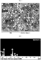
- FIG. 1 illustrates a scanning electron microscopic (SEM) image of the surface of the separator according to Example 1.
- SEM scanning electron microscopic
- FIG. 2 and FIG. 3 illustrate the results of energy dispersive spectrometry (EDS) of the separator according to Example 1.
- EDS energy dispersive spectrometry
- the separator according to Comparative Example 1 includes a heat resistant layer formed by using a binder resin alone on the surface of the separator substrate, without using any ceramic precursor. It can be seen that the separator according to Comparative Example 1 shows high resistance and particularly high heat shrinkage to cause degradation of heat resistance.
- the separator according to Comparative Example 4 includes a heat resistant layer formed by using a binder resin alone without using any separator substrate, and shows high resistance and high heat shrinkage. In the case of the separator according to Comparative Example 2, since only the ceramic precursor is present, the heat resistant layer is cracked and the separator hardly functions as a separator. In Comparative Examples 3 and 5, the ceramic precursor cannot be converted into a ceramic material and a porous structure cannot be formed properly, and thus each separator shows high resistance.
- the separator according to Comparative Example 6 is obtained by using the same amount of ceramic particles instead of a ceramic precursor. It can be seen that the separator according to Comparative Example 6 shows poor resistance characteristics as compared to the separators according to Examples 1-3 having a similar separator thickness.
- Each of the separators according to Examples and Comparative Examples was determined for resistance by the following method.
- Each of the separators according to Examples and Comparative Examples was cut and disposed in 2032 Coin Cell available from Hoshen Co., an electrolyte including 1M LiPF 6 -ethylene carbonate/ethyl methyl carbonate (weight ratio 3:7) was injected thereto so that the separator might be impregnated therewith, and electrical resistance was determined by EIS (Electrochemical Impedance Spectroscopy) at 25°C through alternating current measurement.
- EIS Electrochemical Impedance Spectroscopy
Landscapes
- Chemical & Material Sciences (AREA)
- Chemical Kinetics & Catalysis (AREA)
- Electrochemistry (AREA)
- General Chemical & Material Sciences (AREA)
- Engineering & Computer Science (AREA)
- Manufacturing & Machinery (AREA)
- Inorganic Chemistry (AREA)
- Materials Engineering (AREA)
- Composite Materials (AREA)
- Ceramic Engineering (AREA)
- Cell Separators (AREA)
Applications Claiming Priority (2)
| Application Number | Priority Date | Filing Date | Title |
|---|---|---|---|
| KR20190100504 | 2019-08-16 | ||
| PCT/KR2020/010922 WO2021034061A1 (ko) | 2019-08-16 | 2020-08-14 | 내열층을 포함하는 전기화학소자용 분리막 및 이를 포함하는 이차 전지 |
Publications (2)
| Publication Number | Publication Date |
|---|---|
| EP4007036A1 true EP4007036A1 (de) | 2022-06-01 |
| EP4007036A4 EP4007036A4 (de) | 2022-12-21 |
Family
ID=74659545
Family Applications (1)
| Application Number | Title | Priority Date | Filing Date |
|---|---|---|---|
| EP20855025.1A Pending EP4007036A4 (de) | 2019-08-16 | 2020-08-14 | Separator für elektrochemische vorrichtung mit einer wärmebeständigen schicht und diese enthaltende sekundärbatterie |
Country Status (5)
| Country | Link |
|---|---|
| US (1) | US20220285787A1 (de) |
| EP (1) | EP4007036A4 (de) |
| KR (1) | KR20210020845A (de) |
| CN (1) | CN114270615B (de) |
| WO (1) | WO2021034061A1 (de) |
Family Cites Families (20)
| Publication number | Priority date | Publication date | Assignee | Title |
|---|---|---|---|---|
| JP3771314B2 (ja) * | 1995-03-17 | 2006-04-26 | クラリアント インターナショナル リミティド | SiO2系セラミックス被覆フィルムの製造方法 |
| KR100418859B1 (ko) * | 2002-05-06 | 2004-02-14 | 주식회사 코레드 | 폴리에테르술폰막 제조용 조성물 및 이를 이용한정밀여과용 막의 제조방법 |
| JP5130700B2 (ja) * | 2005-12-12 | 2013-01-30 | 東レ株式会社 | 電池用電極の製造方法、ならびに二次電池 |
| KR101460640B1 (ko) * | 2007-07-06 | 2014-12-02 | 소니 가부시끼가이샤 | 세퍼레이터, 세퍼레이터를 이용한 전지, 및 세퍼레이터를제조하는 방법 |
| KR100998568B1 (ko) * | 2008-03-26 | 2010-12-07 | 한국원자력연구원 | 내열성이 우수한 리튬 이차전지용 분리막 제조방법 및 이를이용하여 제조된 분리막 |
| JP5648481B2 (ja) * | 2010-06-25 | 2015-01-07 | 東レバッテリーセパレータフィルム株式会社 | 複合多孔質膜、複合多孔質膜の製造方法並びにそれを用いた電池用セパレーター |
| KR101305798B1 (ko) * | 2011-11-30 | 2013-09-06 | 롯데케미칼 주식회사 | 다공성 분리막 및 이의 제조방법 |
| TW201351758A (zh) * | 2012-06-11 | 2013-12-16 | Enerage Inc | 電化學裝置隔離膜及其製備方法 |
| WO2014066310A1 (en) * | 2012-10-23 | 2014-05-01 | Cornell University | Ceramic nanofiber separators |
| KR102137129B1 (ko) * | 2012-11-30 | 2020-07-24 | 데이진 가부시키가이샤 | 비수계 이차전지용 세퍼레이터 및 비수계 이차전지 |
| US10186698B2 (en) * | 2013-12-04 | 2019-01-22 | Cornell University | Ceramic-polymer hybrid nanostructures, methods for producing and applications thereof |
| KR20160071539A (ko) * | 2014-12-11 | 2016-06-22 | 삼성에스디아이 주식회사 | 다공성 무기 코팅 분리막, 그 제조 방법 및 이를 이용한 전기 화학 전지 |
| KR102225305B1 (ko) * | 2015-09-25 | 2021-03-10 | 주식회사 엘지화학 | 상분리를 이용하여 무기물 코팅층을 포함하는 분리막을 제조하는 방법 |
| CN107799696A (zh) * | 2016-08-29 | 2018-03-13 | 比亚迪股份有限公司 | 一种锂离子电池隔膜及其制备方法和锂离子电池 |
| US20180254464A1 (en) * | 2017-03-03 | 2018-09-06 | Teijin Limited | Separator for a non-aqueous secondary battery and non-aqueous secondary battery |
| CN107195838B (zh) * | 2017-05-02 | 2020-03-17 | 佛山市金辉高科光电材料有限公司 | 锂离子电池隔膜用的孔径均匀有序的耐热涂层及制备方法 |
| US10355257B2 (en) * | 2017-05-16 | 2019-07-16 | Cornell University | Hybrid separators and the manufacture thereof |
| KR102215328B1 (ko) * | 2018-01-12 | 2021-02-10 | 삼성에스디아이 주식회사 | 이차 전지용 분리막 및 이를 포함하는 리튬 이차 전지 |
| KR102710564B1 (ko) * | 2018-01-29 | 2024-09-26 | 주식회사 엘지에너지솔루션 | 분리막 및 이를 포함하는 전기화학소자 |
| KR102043460B1 (ko) | 2018-02-06 | 2019-11-11 | 주식회사 이노아이엔씨 | 산림 재해 진화대원을 위한 안전관리 시스템 및 이의 사용 방법 |
-
2020
- 2020-08-14 CN CN202080057790.0A patent/CN114270615B/zh active Active
- 2020-08-14 KR KR1020200102800A patent/KR20210020845A/ko active Pending
- 2020-08-14 US US17/632,726 patent/US20220285787A1/en active Pending
- 2020-08-14 EP EP20855025.1A patent/EP4007036A4/de active Pending
- 2020-08-14 WO PCT/KR2020/010922 patent/WO2021034061A1/ko not_active Ceased
Also Published As
| Publication number | Publication date |
|---|---|
| US20220285787A1 (en) | 2022-09-08 |
| EP4007036A4 (de) | 2022-12-21 |
| WO2021034061A1 (ko) | 2021-02-25 |
| KR20210020845A (ko) | 2021-02-24 |
| CN114270615A (zh) | 2022-04-01 |
| CN114270615B (zh) | 2024-09-06 |
Similar Documents
| Publication | Publication Date | Title |
|---|---|---|
| KR102225305B1 (ko) | 상분리를 이용하여 무기물 코팅층을 포함하는 분리막을 제조하는 방법 | |
| US12255351B2 (en) | Separator for electrochemical device and method for manufacturing the same | |
| US12283716B2 (en) | Separator having heat resistant layer for electrochemical device and secondary battery comprising same | |
| EP4235899A2 (de) | Einschichtiger chemisch vernetzter verbundseparator | |
| KR101881584B1 (ko) | 무기물 코팅부와 점착부가 형성된 분리막을 포함하는 단위셀 및 이를 포함하는 전극조립체 | |
| WO2017082259A1 (ja) | 非水系二次電池用セパレータ及び非水系二次電池 | |
| US20230327286A1 (en) | Separator for electrochemical device and method for manufacturing the same | |
| EP3813149A1 (de) | Separator für elektrochemische vorrichtung mit anorganischer überzugsschicht und verfahren zur herstellung davon | |
| JP2015181110A (ja) | 耐熱性微多孔膜、リチウムイオン二次電池用セパレータ及びリチウムイオン二次電池 | |
| US20220384910A1 (en) | Separation Membrane for Electrochemical Device, Electrochemical Device Comprising Same Separation Membrane, and Method for Manufacturing Same Separation Membrane | |
| CN115917779A (zh) | 包括具有优异湿粘附性的绝缘层的用于锂二次电池的正极和包括其的锂二次电池 | |
| KR20220029513A (ko) | 전기화학소자용 분리막 및 이를 포함하는 전기화학소자 | |
| KR101900990B1 (ko) | 리튬이차전지용 전극조립체 및 이를 포함하는 리튬이차전지 | |
| KR102826110B1 (ko) | 용해 온도가 다른 바인더를 포함하는 분리막 및 이의 제조방법 | |
| KR102042463B1 (ko) | 다공성 박막에 전기방사법으로 섬유상 코팅층을 도입한 분리막의 제조 방법 및 이로부터 제조되는 분리막 | |
| KR102042464B1 (ko) | 이온 전도도가 향상된 내열성 코팅층을 포함하는 분리막의 제조 방법 및 이로부터 제조되는 분리막 | |
| KR20230019035A (ko) | 습윤 접착력이 우수한 절연층을 포함하는 리튬 이차전지용 양극 및 이를 포함하는 리튬 이차전지 | |
| EP4007036A1 (de) | Separator für elektrochemische vorrichtung mit einer wärmebeständigen schicht und diese enthaltende sekundärbatterie | |
| KR102830259B1 (ko) | 전기화학소자용 분리막 및 이를 제조하는 방법 | |
| KR102848371B1 (ko) | 습윤 접착력이 우수한 전극용 절연 조성물, 및 이의 제조방법 | |
| KR102194217B1 (ko) | 2종의 분리막이 라미네이션된 분리막 복합체, 이의 제조방법 및 이를 포함하는 리튬 이차전지 | |
| CN120019541A (zh) | 电化学装置用分隔件、包括其的电化学装置及其制造方法 | |
| CN115885420A (zh) | 具有提高的耐热性的用于锂二次电池的隔板 | |
| KR20220131183A (ko) | 내열성이 향상된 리튬 이차전지용 분리막 | |
| CN119731864A (zh) | 电化学装置用分隔件和包括其的电化学装置 |
Legal Events
| Date | Code | Title | Description |
|---|---|---|---|
| STAA | Information on the status of an ep patent application or granted ep patent |
Free format text: STATUS: THE INTERNATIONAL PUBLICATION HAS BEEN MADE |
|
| PUAI | Public reference made under article 153(3) epc to a published international application that has entered the european phase |
Free format text: ORIGINAL CODE: 0009012 |
|
| STAA | Information on the status of an ep patent application or granted ep patent |
Free format text: STATUS: REQUEST FOR EXAMINATION WAS MADE |
|
| 17P | Request for examination filed |
Effective date: 20220224 |
|
| AK | Designated contracting states |
Kind code of ref document: A1 Designated state(s): AL AT BE BG CH CY CZ DE DK EE ES FI FR GB GR HR HU IE IS IT LI LT LU LV MC MK MT NL NO PL PT RO RS SE SI SK SM TR |
|
| DAV | Request for validation of the european patent (deleted) | ||
| DAX | Request for extension of the european patent (deleted) | ||
| A4 | Supplementary search report drawn up and despatched |
Effective date: 20221123 |
|
| RIC1 | Information provided on ipc code assigned before grant |
Ipc: H01M 50/403 20210101ALI20221117BHEP Ipc: H01M 10/052 20100101ALI20221117BHEP Ipc: H01M 50/449 20210101ALI20221117BHEP Ipc: H01M 50/434 20210101ALI20221117BHEP Ipc: H01M 50/426 20210101ALI20221117BHEP Ipc: H01M 50/446 20210101AFI20221117BHEP |