EP4007043A1 - Module de batterie comprenant un élément de dissipation de chaleur, et procédé de fabrication d'élément de dissipation de chaleur - Google Patents
Module de batterie comprenant un élément de dissipation de chaleur, et procédé de fabrication d'élément de dissipation de chaleur Download PDFInfo
- Publication number
- EP4007043A1 EP4007043A1 EP20943108.9A EP20943108A EP4007043A1 EP 4007043 A1 EP4007043 A1 EP 4007043A1 EP 20943108 A EP20943108 A EP 20943108A EP 4007043 A1 EP4007043 A1 EP 4007043A1
- Authority
- EP
- European Patent Office
- Prior art keywords
- heat dissipation
- plate
- battery module
- hole
- sealing member
- Prior art date
- Legal status (The legal status is an assumption and is not a legal conclusion. Google has not performed a legal analysis and makes no representation as to the accuracy of the status listed.)
- Pending
Links
Images




Classifications
-
- H—ELECTRICITY
- H01—ELECTRIC ELEMENTS
- H01M—PROCESSES OR MEANS, e.g. BATTERIES, FOR THE DIRECT CONVERSION OF CHEMICAL ENERGY INTO ELECTRICAL ENERGY
- H01M10/00—Secondary cells; Manufacture thereof
- H01M10/60—Heating or cooling; Temperature control
- H01M10/65—Means for temperature control structurally associated with the cells
- H01M10/656—Means for temperature control structurally associated with the cells characterised by the type of heat-exchange fluid
- H01M10/6567—Liquids
- H01M10/6568—Liquids characterised by flow circuits, e.g. loops, located externally to the cells or cell casings
-
- H—ELECTRICITY
- H01—ELECTRIC ELEMENTS
- H01M—PROCESSES OR MEANS, e.g. BATTERIES, FOR THE DIRECT CONVERSION OF CHEMICAL ENERGY INTO ELECTRICAL ENERGY
- H01M10/00—Secondary cells; Manufacture thereof
- H01M10/60—Heating or cooling; Temperature control
- H01M10/65—Means for temperature control structurally associated with the cells
- H01M10/655—Solid structures for heat exchange or heat conduction
- H01M10/6556—Solid parts with flow channel passages or pipes for heat exchange
-
- B—PERFORMING OPERATIONS; TRANSPORTING
- B29—WORKING OF PLASTICS; WORKING OF SUBSTANCES IN A PLASTIC STATE IN GENERAL
- B29C—SHAPING OR JOINING OF PLASTICS; SHAPING OF MATERIAL IN A PLASTIC STATE, NOT OTHERWISE PROVIDED FOR; AFTER-TREATMENT OF THE SHAPED PRODUCTS, e.g. REPAIRING
- B29C45/00—Injection moulding, i.e. forcing the required volume of moulding material through a nozzle into a closed mould; Apparatus therefor
- B29C45/14—Injection moulding, i.e. forcing the required volume of moulding material through a nozzle into a closed mould; Apparatus therefor incorporating preformed parts or layers, e.g. injection moulding around inserts or for coating articles
- B29C45/14008—Inserting articles into the mould
-
- H—ELECTRICITY
- H01—ELECTRIC ELEMENTS
- H01M—PROCESSES OR MEANS, e.g. BATTERIES, FOR THE DIRECT CONVERSION OF CHEMICAL ENERGY INTO ELECTRICAL ENERGY
- H01M10/00—Secondary cells; Manufacture thereof
- H01M10/05—Accumulators with non-aqueous electrolyte
- H01M10/052—Li-accumulators
-
- H—ELECTRICITY
- H01—ELECTRIC ELEMENTS
- H01M—PROCESSES OR MEANS, e.g. BATTERIES, FOR THE DIRECT CONVERSION OF CHEMICAL ENERGY INTO ELECTRICAL ENERGY
- H01M10/00—Secondary cells; Manufacture thereof
- H01M10/05—Accumulators with non-aqueous electrolyte
- H01M10/058—Construction or manufacture
-
- H—ELECTRICITY
- H01—ELECTRIC ELEMENTS
- H01M—PROCESSES OR MEANS, e.g. BATTERIES, FOR THE DIRECT CONVERSION OF CHEMICAL ENERGY INTO ELECTRICAL ENERGY
- H01M10/00—Secondary cells; Manufacture thereof
- H01M10/60—Heating or cooling; Temperature control
- H01M10/61—Types of temperature control
- H01M10/613—Cooling or keeping cold
-
- H—ELECTRICITY
- H01—ELECTRIC ELEMENTS
- H01M—PROCESSES OR MEANS, e.g. BATTERIES, FOR THE DIRECT CONVERSION OF CHEMICAL ENERGY INTO ELECTRICAL ENERGY
- H01M10/00—Secondary cells; Manufacture thereof
- H01M10/60—Heating or cooling; Temperature control
- H01M10/65—Means for temperature control structurally associated with the cells
- H01M10/655—Solid structures for heat exchange or heat conduction
- H01M10/6551—Surfaces specially adapted for heat dissipation or radiation, e.g. fins or coatings
-
- H—ELECTRICITY
- H01—ELECTRIC ELEMENTS
- H01M—PROCESSES OR MEANS, e.g. BATTERIES, FOR THE DIRECT CONVERSION OF CHEMICAL ENERGY INTO ELECTRICAL ENERGY
- H01M10/00—Secondary cells; Manufacture thereof
- H01M10/60—Heating or cooling; Temperature control
- H01M10/65—Means for temperature control structurally associated with the cells
- H01M10/655—Solid structures for heat exchange or heat conduction
- H01M10/6554—Rods or plates
-
- H—ELECTRICITY
- H01—ELECTRIC ELEMENTS
- H01M—PROCESSES OR MEANS, e.g. BATTERIES, FOR THE DIRECT CONVERSION OF CHEMICAL ENERGY INTO ELECTRICAL ENERGY
- H01M10/00—Secondary cells; Manufacture thereof
- H01M10/60—Heating or cooling; Temperature control
- H01M10/65—Means for temperature control structurally associated with the cells
- H01M10/656—Means for temperature control structurally associated with the cells characterised by the type of heat-exchange fluid
- H01M10/6567—Liquids
-
- H—ELECTRICITY
- H01—ELECTRIC ELEMENTS
- H01M—PROCESSES OR MEANS, e.g. BATTERIES, FOR THE DIRECT CONVERSION OF CHEMICAL ENERGY INTO ELECTRICAL ENERGY
- H01M50/00—Constructional details or processes of manufacture of the non-active parts of electrochemical cells other than fuel cells, e.g. hybrid cells
- H01M50/20—Mountings; Secondary casings or frames; Racks, modules or packs; Suspension devices; Shock absorbers; Transport or carrying devices; Holders
- H01M50/204—Racks, modules or packs for multiple batteries or multiple cells
- H01M50/207—Racks, modules or packs for multiple batteries or multiple cells characterised by their shape
- H01M50/211—Racks, modules or packs for multiple batteries or multiple cells characterised by their shape adapted for pouch cells
-
- H—ELECTRICITY
- H01—ELECTRIC ELEMENTS
- H01M—PROCESSES OR MEANS, e.g. BATTERIES, FOR THE DIRECT CONVERSION OF CHEMICAL ENERGY INTO ELECTRICAL ENERGY
- H01M50/00—Constructional details or processes of manufacture of the non-active parts of electrochemical cells other than fuel cells, e.g. hybrid cells
- H01M50/20—Mountings; Secondary casings or frames; Racks, modules or packs; Suspension devices; Shock absorbers; Transport or carrying devices; Holders
- H01M50/233—Mountings; Secondary casings or frames; Racks, modules or packs; Suspension devices; Shock absorbers; Transport or carrying devices; Holders characterised by physical properties of casings or racks, e.g. dimensions
- H01M50/24—Mountings; Secondary casings or frames; Racks, modules or packs; Suspension devices; Shock absorbers; Transport or carrying devices; Holders characterised by physical properties of casings or racks, e.g. dimensions adapted for protecting batteries from their environment, e.g. from corrosion
-
- H—ELECTRICITY
- H01—ELECTRIC ELEMENTS
- H01M—PROCESSES OR MEANS, e.g. BATTERIES, FOR THE DIRECT CONVERSION OF CHEMICAL ENERGY INTO ELECTRICAL ENERGY
- H01M50/00—Constructional details or processes of manufacture of the non-active parts of electrochemical cells other than fuel cells, e.g. hybrid cells
- H01M50/20—Mountings; Secondary casings or frames; Racks, modules or packs; Suspension devices; Shock absorbers; Transport or carrying devices; Holders
- H01M50/244—Secondary casings; Racks; Suspension devices; Carrying devices; Holders characterised by their mounting method
-
- A—HUMAN NECESSITIES
- A62—LIFE-SAVING; FIRE-FIGHTING
- A62C—FIRE-FIGHTING
- A62C3/00—Fire prevention, containment or extinguishing specially adapted for particular objects or places
- A62C3/16—Fire prevention, containment or extinguishing specially adapted for particular objects or places in electrical installations, e.g. cableways
-
- H—ELECTRICITY
- H01—ELECTRIC ELEMENTS
- H01M—PROCESSES OR MEANS, e.g. BATTERIES, FOR THE DIRECT CONVERSION OF CHEMICAL ENERGY INTO ELECTRICAL ENERGY
- H01M10/00—Secondary cells; Manufacture thereof
- H01M10/60—Heating or cooling; Temperature control
- H01M10/64—Heating or cooling; Temperature control characterised by the shape of the cells
- H01M10/647—Prismatic or flat cells, e.g. pouch cells
-
- H—ELECTRICITY
- H01—ELECTRIC ELEMENTS
- H01M—PROCESSES OR MEANS, e.g. BATTERIES, FOR THE DIRECT CONVERSION OF CHEMICAL ENERGY INTO ELECTRICAL ENERGY
- H01M2200/00—Safety devices for primary or secondary batteries
- H01M2200/10—Temperature sensitive devices
-
- H—ELECTRICITY
- H01—ELECTRIC ELEMENTS
- H01M—PROCESSES OR MEANS, e.g. BATTERIES, FOR THE DIRECT CONVERSION OF CHEMICAL ENERGY INTO ELECTRICAL ENERGY
- H01M2220/00—Batteries for particular applications
- H01M2220/10—Batteries in stationary systems, e.g. emergency power source in plant
-
- H—ELECTRICITY
- H01—ELECTRIC ELEMENTS
- H01M—PROCESSES OR MEANS, e.g. BATTERIES, FOR THE DIRECT CONVERSION OF CHEMICAL ENERGY INTO ELECTRICAL ENERGY
- H01M2220/00—Batteries for particular applications
- H01M2220/20—Batteries in motive systems, e.g. vehicle, ship, plane
-
- H—ELECTRICITY
- H01—ELECTRIC ELEMENTS
- H01M—PROCESSES OR MEANS, e.g. BATTERIES, FOR THE DIRECT CONVERSION OF CHEMICAL ENERGY INTO ELECTRICAL ENERGY
- H01M2220/00—Batteries for particular applications
- H01M2220/30—Batteries in portable systems, e.g. mobile phone, laptop
-
- Y—GENERAL TAGGING OF NEW TECHNOLOGICAL DEVELOPMENTS; GENERAL TAGGING OF CROSS-SECTIONAL TECHNOLOGIES SPANNING OVER SEVERAL SECTIONS OF THE IPC; TECHNICAL SUBJECTS COVERED BY FORMER USPC CROSS-REFERENCE ART COLLECTIONS [XRACs] AND DIGESTS
- Y02—TECHNOLOGIES OR APPLICATIONS FOR MITIGATION OR ADAPTATION AGAINST CLIMATE CHANGE
- Y02E—REDUCTION OF GREENHOUSE GAS [GHG] EMISSIONS, RELATED TO ENERGY GENERATION, TRANSMISSION OR DISTRIBUTION
- Y02E60/00—Enabling technologies; Technologies with a potential or indirect contribution to GHG emissions mitigation
- Y02E60/10—Energy storage using batteries
-
- Y—GENERAL TAGGING OF NEW TECHNOLOGICAL DEVELOPMENTS; GENERAL TAGGING OF CROSS-SECTIONAL TECHNOLOGIES SPANNING OVER SEVERAL SECTIONS OF THE IPC; TECHNICAL SUBJECTS COVERED BY FORMER USPC CROSS-REFERENCE ART COLLECTIONS [XRACs] AND DIGESTS
- Y02—TECHNOLOGIES OR APPLICATIONS FOR MITIGATION OR ADAPTATION AGAINST CLIMATE CHANGE
- Y02P—CLIMATE CHANGE MITIGATION TECHNOLOGIES IN THE PRODUCTION OR PROCESSING OF GOODS
- Y02P70/00—Climate change mitigation technologies in the production process for final industrial or consumer products
- Y02P70/50—Manufacturing or production processes characterised by the final manufactured product
Definitions
- the present invention relates to a battery module including a heat dissipation member and a method of manufacturing the heat dissipation member, and more particularly to a battery module including a heat dissipation member having a through-hole formed therein so as to prevent the occurrence of a thermal runaway phenomenon by directly injecting water into a battery cell that has caught fire and a method of manufacturing the heat dissipation member.
- a lithium secondary battery which is capable of being charged and discharged, is suitable to be used as a built-in battery cell, since it is unnecessary to replace the battery cell. Stability of the lithium secondary battery has been rapidly improved and capacity of the lithium secondary battery has also been rapidly increased. Consequently, the lithium secondary battery has been applied to various devices.
- the lithium secondary battery has been widely used not only as an energy source for a wireless mobile device, which is a small multifunctional product, or a wearable device configured to be put on the body but also as an energy source for electric vehicles and hybrid electric vehicles, which have been presented as alternatives to existing gasoline and diesel vehicles causing air pollution or as an energy storage system (ESS).
- ESS energy storage system
- the lithium secondary battery is used as a large-capacity, high-output energy source, as described above, it becomes very important to guarantee safety of the lithium secondary battery.
- a method of preventing heat transfer between battery cells or cooling a battery cell that has caught fire using a structure in which a thermal insulation material or a fire-extinguishing agent is provided inside or outside the battery module or the battery pack may be used.
- the above method may solve a problem in that the facility and space necessary to provide the separate water injection device are needed, but cost of the battery module or the battery pack is increased due to high price of the thermal insulation material or the fire-extinguishing agent.
- the volume of the battery module or the battery pack is increased due to addition of separate parts, whereby energy density is reduced.
- the amount of the fire-extinguishing agent provided in the battery cell is too small to remove all of the thermal energy discharged from the battery cell, it is difficult to prevent the battery cell from catching fire.
- Patent Document 1 discloses an automatic fire-extinguishing device for energy storage systems, which includes a carbon dioxide supply unit including a carbon dioxide supply member in which highpressure carbon dioxide is stored in a compressed state such that carbon dioxide is supplied into a fire-extinguishing line in a powerless fashion without application of separate power.
- a carbon dioxide supply unit including a carbon dioxide supply member in which highpressure carbon dioxide is stored in a compressed state such that carbon dioxide is supplied into a fire-extinguishing line in a powerless fashion without application of separate power.
- the constructions, such as the fire-extinguishing line and the carbon dioxide supply member are separately needed, whereby a problem in that the size of an energy storage system is increased is not solved.
- Patent Document 2 discloses a battery system including a reservoir configured to store a fire-extinguishing agent and a conduit means configured to guide the fire-extinguishing agent, wherein the conduit means is located so as to collide with a vent-gas jet discharged through a vent hole formed in any one of a plurality of battery cells and wherein the conduit means is configured to be melted by the vent-gas jet.
- Patent Document 2 Since the battery system of Patent Document 2 includes the reservoir configured to store the fire-extinguishing agent and the conduit means configured to guide the fire-extinguishing agent, a problem in that the volume of the battery system is increased is still not solved.
- the present invention has been made in view of the above problems, and it is an object of the present invention to provide a battery module including a heat dissipation member having a structure in which a refrigerant for the heat dissipation member is directly injected to a battery cell that has caught fire such that, when a battery cell catches fire or explodes, thermal energy is prevented from being transferred to battery cells adjacent thereto and a method of manufacturing the heat dissipation member.
- a battery module includes a battery cell stack comprising a plurality of stacked pouch-shaped battery cells, a battery module housing configured to receive the battery cell stack, and a heat dissipation member coupled to a portion of the battery module housing, wherein the heat dissipation member has a through-hole formed in a heat dissipation plate disposed so as to face the battery cell stack and a sealing member is added to the through-hole.
- the battery module housing may include an upper plate and a lower plate
- the heat dissipation member may include a heat dissipation plate and a refrigerant flow portion
- the upper plate and the heat dissipation plate may be coupled to each other in a shape in which the refrigerant flow portion is defined between the upper plate and the heat dissipation plate.
- the heat dissipation member may be configured such that the lower plate and the heat dissipation plate are coupled to each other in a shape in which the refrigerant flow portion is defined between the lower plate and the heat dissipation plate.
- the sealing member may be made of a material that is melted by high-temperature gas or sparks discharged from each of the pouch-shaped battery cells.
- the through-hole may be opened by melting of the sealing member, and a refrigerant may be injected into the pouch-shaped battery cell through the through-hole.
- the refrigerant may be a coolant, and the coolant may include no combustible material.
- each of the upper plate and the lower plate may be provided with a flow channel configured to guide the flow of the coolant.
- the battery module housing may include an upper plate and a lower plate, a water tank configured to function as the heat dissipation member may be coupled to the inner surface of the upper plate, the water tank may be provided in a second surface thereof opposite a first surface thereof coupled to the inner surface of the upper plate with a through-hole, and a sealing member may be added to the through-hole.
- the battery module housing may include an upper plate and a lower plate, a water tank configured to function as the heat dissipation member may be coupled to an inner surface of the lower plate, the water tank may be provided in a second surface thereof opposite a first surface thereof coupled to the inner surface of the lower plate with a through-hole, and a sealing member may be added to the through-hole.
- the through-hole may be formed at the position at which a coolant can be supplied to the pouch-shaped battery cell catching fire, and the number of the through-holes may be set depending on the number and size of the pouch-shaped battery cells.
- the sealing member may fill the through-hole, and the sealing member may include an extension portion formed at the inner surface and the outer surface of the heat dissipation plate so as to further extend outwards from the circumference of the through-hole.
- a recess may be formed in the portion of each of the inner surface and the outer surface of the heat dissipation plate at which the extension portion is formed.
- the heat dissipation plate having the recess formed therein may have at least one vertical section selected from the group consisting of a polygonal shape, a semicircular shape, and a semielliptical shape.
- the present invention provides a method of manufacturing a heat dissipation member included in the battery module.
- the method of manufacturing the heat dissipation member includes (a) disposing a flat plate for the heat dissipation plate of the heat dissipation member between a die and a holder, (b) punching the flat plate to form the through-hole, thereby manufacturing a heat dissipation plate, (c) mounting the heat dissipation plate in a mold for insert extrusion molding, (d) fixing the heat dissipation plate to the mold and injecting a resin for the sealing member, and (e) removing the mold and collecting the heat dissipation plate having the sealing member added thereto, wherein a protrusion configured to form a recess in the heat dissipation plate is formed in each of the die and the holder.
- the heat dissipation plate may be coupled to each of an upper plate and a lower plate of the battery module housing so as to be spaced apart therefrom, and a refrigerant flow portion configured to allow a refrigerant to be introduced thereinto and to be discharged therefrom may be defined in the space therebetween.
- the heat dissipation plate may comprise a water tank coupled to each of the upper plate and the lower plate of the battery module housing, and the heat dissipation plate may be disposed at the other surface of the water tank that is opposite one surface of the water tank coupled to each of the upper plate and the lower plate.
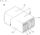
- FIG. 1 is a perspective view of a battery module according to the present invention.
- the battery module 100 includes a battery module housing configured to receive therein a battery cell stack in which a plurality of pouch-shaped battery cells 101 is stacked and a heat dissipation member disposed at each of the upper surface and the lower surface of the battery cell stack.
- bidirectional pouch-shaped battery cells 101 As the plurality of pouch-shaped battery cells 101, bidirectional pouch-shaped battery cells 101, each of which has electrode leads 102 protruding in opposite directions, are shown in FIG. 1 .
- unidirectional pouch-shaped battery cells each of which has a positive electrode lead and a negative electrode lead protruding in the same direction, may be used.
- the battery module housing includes an upper plate 110 disposed at the upper part of the battery cell stack, a lower plate 120 disposed at the lower part of the battery cell stack, and a side plate 130 disposed between the upper plate 110 and the lower plate 120, the side plate being disposed at the side of the battery cell stack.
- an end plate (not shown) may be coupled to the upper plate 110, the lower plate, and the side plate 130, whereby the battery module housing may be assembled.
- the shape of the battery module housing is not limited to the structure shown in FIG. 1 . Unlike what is shown in FIG. 1 , a mono frame or a U frame may be used for the battery module housing.
- FIG. 2 is a vertical sectional view of a battery module according to an embodiment.
- a battery cell stack in which a plurality of pouch-shaped battery cells 101 is stacked is received in a battery module housing including an upper plate 110 and a lower plate 120.
- a heat dissipation member 200 includes a heat dissipation plate 210 and a refrigerant flow portion 220 configured to allow a refrigerant to be introduced thereinto, to flow therein, and to be discharged therefrom.
- the heat dissipation plate 210 is coupled to the upper plate 110 so as to be spaced apart from the upper plate, and the refrigerant flow portion 220 is defined in the space between the heat dissipation plate and the upper plate. Consequently, the upper plate 110, the heat dissipation plate 210, and the refrigerant flow portion 220 form an integrated structure.
- the heat dissipation member 200 is located at the upper part of the battery cell stack in a state of being coupled to the upper plate 110 so as to be integrated therewith.
- a heat dissipation member 200' includes a heat dissipation plate 210 and a refrigerant flow portion 220 configured to allow a refrigerant to be introduced thereinto, to flow therein, and to be discharged therefrom.
- the heat dissipation plate 210 is coupled to the lower plate 120 so as to be spaced apart from the lower plate, and the refrigerant flow portion 220 is defined in the space between the heat dissipation plate and the lower plate. Consequently, the lower plate 120, the heat dissipation plate 210, and the refrigerant flow portion 220 form an integrated structure.
- the heat dissipation member 200' is located at the lower part of the battery cell stack in a state of being coupled to the lower plate 120 so as to be integrated therewith.
- a through-hole 230 is formed in the heat dissipation plate 210, and a sealing member 240 is added to the through-hole 230.
- the sealing member 240 is made of a material that is melted by high-temperature gas or sparks discharged from the pouch-shaped battery cells 101. That is, in a normal state as in the pouch-shaped battery cell 101, the state in which the through-hole 230 is sealed by the sealing member 240 is maintained. When temperature is increased or fire breaks out as in the pouch-shaped battery cell 103, however, the sealing member 240 is melted, whereby the through-hole 230 is opened.
- the refrigerant from the refrigerant flow portion 220 is directly injected into the pouch-shaped battery cell 103 through the opened through-hole 230. As a result, the pouch-shaped battery cell that overheats or catches fire is rapidly cooled, whereby it is possible to rapidly prevent propagation of thermal runaway.
- the sealing member is made of a material that is melted by high-temperature gas or sparks discharged due to venting of the pouch-shaped battery cell having increased temperature.
- a thermoplastic polymer resin having a melting point of about 200°C or lower may be applied.
- a material having a melting point between about 100°C and about 200°C, such as polyethylene or polypropylene, may be used as the thermoplastic polymer resin.
- an additive included in the coolant it is necessary to prevent the pouch-shaped battery cell from having increasing flames or exploding due to injection of the coolant in consideration of the fact that the coolant is directly injected to the pouch-shaped battery cell. Consequently, it is preferable for an additive included in the coolant to include no combustible material.
- the amount of the additive may be provided to such an extent that it is possible to prevent secondary explosion of the pouch-shaped battery cell and at the same time the additive is used as an antifreeze in order to prevent freezing of the coolant.
- the heat dissipation member 200 and the heat dissipation member 200' of FIG. 2 are identical in construction to each other except that the heat dissipation member 200 is configured such that the heat dissipation plate and the upper plate are coupled to each other and the heat dissipation member 200' is configured such that the heat dissipation plate and the lower plate are coupled to each other. Consequently, a description will be given based on the heat dissipation member 200.
- FIG. 3 is a perspective view and a plan view of the heat dissipation member according to the present invention in the state in which the heat dissipation member is exploded.
- FIG. 3 a perspective view of the heat dissipation member in the state in which the heat dissipation plate 210 is removed from the heat dissipation member is shown in FIG. 3(a) and a plan view of the heat dissipation plate 210 is shown in FIG. 3(b) in order to described the inner structure of the heat dissipation member in which the upper plate 110 and the heat dissipation plate 210 are coupled to each other.
- the upper plate 110 is provided with partition walls 215 configured to guide the flow of the coolant used as the refrigerant, and a flow channel is defined between the partition walls 215.
- the upper plate 110 is provided at the outer periphery of one side thereof with a coolant inlet and a coolant outlet formed so as to be adjacent to each other as indicated by arrows.
- the coolant inlet and a coolant outlet are formed in a middle portion of the outer periphery of one side of the upper plate in a lateral direction a thereof.
- the temperature of the coolant introduced through the coolant inlet is the lowest and the temperature of the coolant discharged through the coolant outlet is the highest.
- the deviation in temperature of all of the coolant that flows in the refrigerant flow portion may be small.
- the entire heat dissipation member may exhibit uniform heat dissipation efficiency.
- FIG. 3(b) shows the state in which the through-hole 230 is formed in the heat dissipation plate 210.
- Through-holes 230 are disposed in the heat dissipation plate 210 so as to be spaced apart from each other at uniform intervals in a horizontal direction and a vertical direction.
- the through-hole must be formed at a position at which the coolant can be supplied to the pouch-shaped battery cell catching fire. That is, it is preferable for at least one through-hole to be disposed for each pouch-shaped battery cell such that the coolant can be supplied to all of the pouch-shaped battery cells. Consequently, the number and intervals of the through-holes may be adjusted depending on the number and size of the pouch-shaped battery cells.
- FIG. 4 is a plan view of a heat dissipation plate according to the present invention.
- through-holes 230' and 230" formed in the heat dissipation plate 210 are different in shape from the through-holes 230 of FIG. 3 .
- the through-holes 230' are formed obliquely such that one through-hole can cover two or more pouch-shaped battery cells, and the through-holes 230" are formed in a direction perpendicular to the longitudinal direction L of each of the battery cells such that one through-hole can cover two or more pouch-shaped battery cells.
- the through-holes are formed as described above, when the sealing member is melted by heat generated from any one of the pouch-shaped battery cells and explosion thereof, the through-hole is greatly formed, whereby the coolant may also be supplied to the surface of at least one battery cell that is located adjacent to the battery cell that has generated heat and exploded but has not generated heat and exploded. Consequently, it is possible to reduce the temperature of the battery cells that have not generated heat and exploded, and therefore it is possible to prevent the occurrence of a thermal runaway phenomenon.
- FIG. 5 is a partial enlarged view of FIG. 2 .
- the refrigerant flow portion 220 is formed between the heat dissipation plate 210 and the upper plate 110, and the partition wall 215 is formed in the refrigerant flow portion 220.
- the flow channel of the refrigerant is defined by the partition wall 215.
- a space may be formed between the battery cell stack and the heat dissipation plate 210, and individual battery cells 101 may have different deviations in distance between the battery cells and the heat dissipation plate 210.
- Heat dissipation efficiency in which heat in the battery module is discharged out of the battery module is reduced by the space formed between the battery cell stack and the heat dissipation plate 210 as described above.
- the space between the battery cell stack and the heat dissipation plate 210 may be filled with a thermal interface material (TIM) 390.
- TIM thermal interface material
- thermal interface material 390 increases thermal contact area between the battery cell stack and the heat dissipation plate, it is possible to rapidly discharge thermal energy generated in the battery cell stack into the battery module.
- the temperature of the sealing member may not reach a melting temperature. For this reason, addition of the thermal interface material may be omitted.
- the thermal interface material may not be formed at the lower part of the through-hole of the heat dissipation plate but may be added to the remaining portion thereof.
- thermal energy of the vented battery cell may be directly transferred to the sealing member without loss even in the case in which the thermal interface material is added.
- the sealing member may be melted, and therefore the refrigerant may be supplied to the vented battery cell.
- the sealing member 240 is added to the through-hole 230, which is formed through the heat dissipation plate 210.
- the sealing member 240 fills the through-hole 230, and includes an extension portion 241 formed at the inner surface 211 of the heat dissipation plate and the outer surface 212 of the heat dissipation plate so as to further extend outwards from the circumference of the through-hole 230.
- the extension portion 241 is formed at the sealing member 240, it is possible to prevent the sealing member 240 from being removed by the pressure of the coolant flowing in the refrigerant flow portion, thereby preventing the through-hole from being opened.
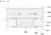
- FIG. 6 is a vertical sectional enlarged view of a battery module in which a sealing member is added to a heat dissipation plate having a recess formed therein.
- a refrigerant flow portion 320 is formed between an upper plate 110 and a heat dissipation plate 310, and a sealing member 340 is added to a through hole formed in the heat dissipation plate 310.
- the sealing member 340 includes an extension portion 341, and a recess 314 is formed in the portion of each of an inner surface 311 of the heat dissipation plate and an outer surface 312 of the heat dissipation plate at which the extension portion 341 is formed.
- a portion of the sealing member constituting the extension portion 341 is inserted into the recess 314 to form an insertion portion 345. Consequently, it is possible to prevent the sealing member from being removed by the pressure of a coolant, thereby preventing the through-hole from being opened.
- the sealing member including the extension portion described above an insert injection molding method of injecting a resin for the sealing member to the heat dissipation plate having the recess formed therein may be used.
- the portion of the sealing portion that fills the through-hole may be formed as a central portion of a sealing member having a shape and size corresponding to the shape and size of the through-hole, and a separate member may be added to the central portion of the sealing member to form an extension portion.
- the central portion of the sealing member and the separately added extension portion may be coupled to each other by adhesion using an adhesive material, screw engagement, or interference fitting.
- the coupling method is not restricted.
- the central portion of the sealing member may be made of a thermoplastic polymer resin that is melted at high temperature
- the separately added extension portion may be made of a material that is not melted at high temperature.
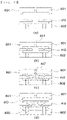
- FIG. 7 is a vertical sectional view showing the state in which a sealing member is added to a heat dissipation plate having a recess formed therein.
- each of sealing members 440, 540, and 640 is added to a corresponding one of heat dissipation plates 410, 510, and 610.
- the portions of the heat dissipation plates 410, 510, and 610 that join extension portions are provided with recesses 414, 514, and 614, respectively, and insertion portions 445, 545, and 645 are formed in the recesses 414, 514, and 614, respectively.
- each of the portions of the heat dissipation plates 410, 510, and 610 in which the recesses 414, 514, and 614 are formed, respectively, may be at least one selected from the group consisting of a polygonal shape, including a triangular shape and a trapezoidal shape, a semicircular shape, and a semielliptical shape or a combination thereof.
- the thickness of a central portion 641 of the sealing member 640 is formed so as to be less than the thickness of a central portion of the sealing member 410 and the thickness of a central portion of the sealing member 510.
- the portion of the sealing member that seals a through-hole is formed so as to have a relatively small thickness, as described above, a time until the sealing member is melted and the through-hole is opened may be shortened, whereby it is possible to rapidly supply a refrigerant to a battery cell.
- FIG. 8 is a vertical sectional view of a battery pack according to another embodiment.
- a battery module housing includes an upper plate 110' and a lower plate 120', and a battery cell stack in which pouch-shaped battery cells 101 are arranged so as to be stacked is received in the battery module housing.
- a water tank 260 configured to function as a heat dissipation member is coupled to the inner surface of the upper plate 110'.
- the water tank 260 includes a first surface 261 coupled to the inner surface of the upper plate 110' and a second surface 263 disposed so as to face the first surface 261, and a coolant 262 is received in a space defined between the first surface 261 and the second surface 263.
- a through-hole 267 is formed in the second surface 263, and a sealing member 268 is added to the through-hole 267.
- the sealing member 268 is made of a material that is melted by high-temperature gas or sparks discharged from the pouch-shaped battery cell 101 as the result of being opened.
- the sealing member 268 is melted, whereby the through-hole 267 is opened.
- the coolant 262 is directly injected into the pouch-shaped battery cell 101 that has caught fire. Consequently, it is possible to cool the pouch-shaped battery cell 101 that has caught fire and to extinguish the fire.
- a water tank 260' includes a first surface 261' coupled to the inner surface of the lower plate 120' and a second surface 263' disposed so as to face the first surface 261', and a coolant 262' is received in a space defined between the first surface 261' and the second surface 263'.
- a through-hole 267' is formed in the second surface 263', and a sealing member 268' is added to the through-hole 267' .
- a description of the water tank 268 is equally applicable to melting of the sealing member 268' due to venting or catching fire of the pouch-shaped battery cell 101 and effects resulting therefrom.
- FIG. 9 is a front view schematically showing a heat dissipation plate manufacturing process
- FIG. 10 is a front view schematically showing a process of adding a sealing member to a heat dissipation plate.
- FIGS. 9 and 10 A method of manufacturing a heat dissipation member included in a battery module according to the present invention will be described with reference to FIGS. 9 and 10 .
- the method of manufacturing the heat dissipation member includes (a) a step of disposing a flat plate for a heat dissipation plate of the heat dissipation member between a die and a holder, (b) a step of punching the flat plate using a punching machine to form a through-hole, thereby manufacturing a heat dissipation plate, (c) a step of mounting the heat dissipation plate in a mold for insert extrusion molding, (d) a step of fixing the heat dissipation plate to the mold and injecting a resin for a sealing member, and (e) a step of removing the mold and collecting a heat dissipation plate having a sealing member added thereto, wherein a protrusion configured to form a recess in the heat dissipation plate may be formed in each of the die and the holder.
- FIGS. 9 and 10 a process of manufacturing the heat dissipation plate 410 shown in FIG. 7(a) is shown.
- a flat plate 401 for a heat dissipation plate of a heat dissipation member may be disposed between a die 710 and a holder 720, and a portion of the flat plate at which a through-hole is to be formed may be punched using a punching machine 730 in order to form the through-hole, whereby the heat dissipation plate 410 may be manufactured.
- a cut portion 217 formed as the result of cutting using the punching machine 730 is removed.
- Protrusions 711 and 721 are formed on the die 710 and the holder 720, respectively, and recesses 414 having shapes and sizes corresponding to the shapes and sizes of the protrusions 711 and 721 are formed in the heat dissipation plate 410.
- An insert extrusion molding method may be used as a method of forming a sealing member 440 at the heat dissipation plate 410.
- the heat dissipation plate 410 is disposed between an upper mold 801 and a lower mold 802. Subsequently, a resin 447 for a sealing member is injected through an injection port 811 formed in the upper mold 801. After the resin 447 for a sealing member is dried, a heat dissipation plate 410 having a sealing member 440 added thereto in the shape of an inner space formed between the upper mold 801 and the lower mold 802 is formed. A portion of the sealing member is inserted into the recesses 414 of the heat dissipation plate 410, whereby it is possible to stably fix the sealing member 440 to the heat dissipation plate 410.
- the heat dissipation plate manufactured as described above is coupled to each of an upper plate and a lower plate of a battery module housing so as to be spaced apart therefrom, whereby it is possible to manufacture a heat dissipation member having a structure in which a refrigerant is introduced into and discharged from the space.
- the heat dissipation plate may constitute a water tank coupled to each of the upper plate and the lower plate of the battery module housing, and the heat dissipation plate may be disposed at the other surface of the water tank that is opposite one surface of the water tank coupled to each of the upper plate and the lower plate.
- a battery module according to the present invention is configured such that the structure of a conventional heat dissipation member is changed without the addition of a separate additional construction in order to rapidly cool a battery cell that has caught fire, whereby it is possible to reliably inhibit a thermal runaway phenomenon of the battery cell while minimizing an increase in volume of the battery module.
- a refrigerant is directly injected into the battery cell through the heat dissipation member, whereby it is possible to rapidly reduce the temperature of the battery cell.
- a through-hole is formed in the heat dissipation member, and the sealing member is added to the through-hole to seal the through-hole, whereby it is possible to minimize an increase in weight of the battery module in spite of the addition of a fire-extinguishing structure.
- a heat dissipation member configured to allow a refrigerant to be injected into the battery cell is used, whereby it is also possible to obtain a thermal diffusion blocking effect for a large-capacity battery module.
- water is injected into a battery cell instead of an expensive fire-extinguishing agent, whereby it is possible to reduce production cost.
Landscapes
- Chemical & Material Sciences (AREA)
- Chemical Kinetics & Catalysis (AREA)
- Electrochemistry (AREA)
- General Chemical & Material Sciences (AREA)
- Engineering & Computer Science (AREA)
- Manufacturing & Machinery (AREA)
- Health & Medical Sciences (AREA)
- Public Health (AREA)
- Business, Economics & Management (AREA)
- Emergency Management (AREA)
- Mechanical Engineering (AREA)
- Battery Mounting, Suspending (AREA)
- Secondary Cells (AREA)
Applications Claiming Priority (2)
| Application Number | Priority Date | Filing Date | Title |
|---|---|---|---|
| KR1020200079312A KR102690299B1 (ko) | 2020-06-29 | 2020-06-29 | 방열부재를 포함하는 전지모듈 및 상기 방열부재의 제조방법 |
| PCT/KR2020/017427 WO2022004972A1 (fr) | 2020-06-29 | 2020-12-02 | Module de batterie comprenant un élément de dissipation de chaleur, et procédé de fabrication d'élément de dissipation de chaleur |
Publications (2)
| Publication Number | Publication Date |
|---|---|
| EP4007043A1 true EP4007043A1 (fr) | 2022-06-01 |
| EP4007043A4 EP4007043A4 (fr) | 2023-09-06 |
Family
ID=79316365
Family Applications (1)
| Application Number | Title | Priority Date | Filing Date |
|---|---|---|---|
| EP20943108.9A Pending EP4007043A4 (fr) | 2020-06-29 | 2020-12-02 | Module de batterie comprenant un élément de dissipation de chaleur, et procédé de fabrication d'élément de dissipation de chaleur |
Country Status (7)
| Country | Link |
|---|---|
| US (1) | US11978876B2 (fr) |
| EP (1) | EP4007043A4 (fr) |
| JP (1) | JP7282902B2 (fr) |
| KR (1) | KR102690299B1 (fr) |
| CN (1) | CN114128012B (fr) |
| AU (1) | AU2020456793A1 (fr) |
| WO (1) | WO2022004972A1 (fr) |
Cited By (4)
| Publication number | Priority date | Publication date | Assignee | Title |
|---|---|---|---|---|
| EP4329047A3 (fr) * | 2022-08-23 | 2024-05-08 | Huawei Digital Power Technologies Co., Ltd. | Module de batterie et système de stockage d'énergie |
| EP4213288A4 (fr) * | 2021-05-28 | 2024-12-11 | LG Energy Solution, Ltd. | Dispositif de refroidissement, module de batterie, système de stockage d'énergie comprenant ces derniers, et véhicule automobile |
| DE102023128749A1 (de) | 2023-08-18 | 2025-02-20 | Webasto SE | Batteriemodul mit Pouch-Zellen |
| EP4560813A4 (fr) * | 2022-09-16 | 2025-12-17 | Lg Energy Solution Ltd | Boîtier de batterie et batterie le comprenant |
Families Citing this family (25)
| Publication number | Priority date | Publication date | Assignee | Title |
|---|---|---|---|---|
| US20230155220A1 (en) * | 2020-10-05 | 2023-05-18 | Turun Ammattikorkeakoulu Oy | Battery lid and battery assembly |
| EP4016699A1 (fr) * | 2020-12-17 | 2022-06-22 | Volvo Car Corporation | Système de gestion de température |
| KR20220152918A (ko) * | 2021-05-10 | 2022-11-17 | 삼성에스디아이 주식회사 | 에너지 저장 시스템의 소화 시스템 |
| EP4718574A2 (fr) * | 2021-12-27 | 2026-04-01 | LG Energy Solution, Ltd. | Bloc-batterie à sécurité améliorée |
| KR102856932B1 (ko) * | 2022-02-08 | 2025-09-05 | 주식회사 엘지에너지솔루션 | 배터리 랙 및 이를 포함하는 전력 저장 장치 |
| KR20230124138A (ko) * | 2022-02-17 | 2023-08-25 | 주식회사 엘지에너지솔루션 | 전지 팩 및 이를 포함하는 디바이스 |
| EP4461595A4 (fr) * | 2022-03-10 | 2025-06-04 | LG Energy Solution, Ltd. | Dispositif comprenant un système de refroidissement |
| KR20230133621A (ko) * | 2022-03-11 | 2023-09-19 | 주식회사 엘지에너지솔루션 | 배터리 팩 및 이를 포함하는 전력 저장 장치 |
| KR20230135998A (ko) * | 2022-03-17 | 2023-09-26 | 주식회사 엘지에너지솔루션 | 히트 싱크, 히트 싱크의 제조방법 및 배터리 모듈 |
| WO2023182841A1 (fr) * | 2022-03-23 | 2023-09-28 | 주식회사 엘지에너지솔루션 | Module de batterie, et bloc-batterie et automobile le comprenant |
| TWI833208B (zh) * | 2022-04-26 | 2024-02-21 | 新盛力科技股份有限公司 | 具有熱防護機制的電池設備 |
| EP4325635B1 (fr) * | 2022-04-29 | 2026-03-11 | LG Energy Solution, Ltd. | Bloc-batterie à performance de refroidissement améliorée |
| JP7730986B2 (ja) * | 2022-06-10 | 2025-08-28 | エルジー エナジー ソリューション リミテッド | バッテリーパック及びこれを含む自動車 |
| WO2024019473A1 (fr) * | 2022-07-18 | 2024-01-25 | 주식회사 엘지에너지솔루션 | Module de batterie et bloc-batterie comprenant une partie de refroidissement |
| WO2024019467A1 (fr) * | 2022-07-18 | 2024-01-25 | 주식회사 엘지에너지솔루션 | Module de batterie et bloc-batterie comprenant une unité de refroidissement |
| US20240097236A1 (en) * | 2022-09-21 | 2024-03-21 | Viridi Parente, Inc. | Stacking frame and cooling system for battery cells |
| KR20240045611A (ko) * | 2022-09-30 | 2024-04-08 | 주식회사 엘지에너지솔루션 | 냉각 부재 및 이를 포함하는 전지 팩 |
| KR102679870B1 (ko) * | 2023-02-27 | 2024-07-02 | 성원하이텍(주) | 연소가스 배출과 소화용제의 유입이 용이한 전기차 배터리팩 케이스 |
| CN116544574B (zh) * | 2023-05-17 | 2023-10-24 | 智泰新能源(东台)有限公司 | 一种储能电池组 |
| KR20240171471A (ko) * | 2023-05-30 | 2024-12-09 | 삼성에스디아이 주식회사 | 배터리 팩 소화 시스템 |
| KR20250014490A (ko) * | 2023-07-20 | 2025-02-03 | 삼성에스디아이 주식회사 | 배터리 팩 |
| ES3063836T3 (en) * | 2023-09-14 | 2026-04-20 | Lg Energy Solution Ltd | Battery cell assembly and battery pack including the same |
| KR20250056009A (ko) * | 2023-10-18 | 2025-04-25 | 삼성에스디아이 주식회사 | 배터리 팩 및 배터리 팩의 소화 방법 |
| KR20250079478A (ko) * | 2023-11-27 | 2025-06-04 | 삼성에스디아이 주식회사 | 에너지 저장 시스템 |
| CN222072062U (zh) * | 2024-04-01 | 2024-11-26 | 株式会社Aesc日本 | 电池包 |
Family Cites Families (16)
| Publication number | Priority date | Publication date | Assignee | Title |
|---|---|---|---|---|
| JP2010040420A (ja) * | 2008-08-07 | 2010-02-18 | Sanyo Electric Co Ltd | 車両用の電源装置 |
| KR101057556B1 (ko) * | 2010-02-03 | 2011-08-17 | 에스비리모티브 주식회사 | 배터리 시스템 및 그 구동 방법 |
| KR101451873B1 (ko) * | 2010-12-30 | 2014-10-17 | 에스케이이노베이션 주식회사 | 유입구와 유출구가 수직구조인 배터리 팩 |
| US9406917B2 (en) * | 2011-07-07 | 2016-08-02 | Federal Express Corporation | Battery cooling method and system |
| KR20160113888A (ko) * | 2015-03-23 | 2016-10-04 | 삼성에스디아이 주식회사 | 배터리 팩 |
| JP2017147128A (ja) * | 2016-02-17 | 2017-08-24 | 三菱重工業株式会社 | 電池モジュール、および、電池システム |
| EP3333932B1 (fr) * | 2016-12-06 | 2019-02-13 | Samsung SDI Co., Ltd. | Système de batterie |
| CN106654417B (zh) * | 2017-01-26 | 2023-04-11 | 合肥国轩高科动力能源有限公司 | 电池液冷装置和电池系统 |
| CN106816668A (zh) | 2017-03-22 | 2017-06-09 | 北京航盛新能科技有限公司 | 一种动力电池热失控降温灭火液冷装置、监控系统及方法 |
| CN206650148U (zh) | 2017-03-22 | 2017-11-17 | 北京航盛新能科技有限公司 | 一种动力电池热失控降温灭火液冷装置、监控系统 |
| KR101984817B1 (ko) | 2017-05-11 | 2019-05-31 | 주식회사 대경산전 | 에너지 저장시스템용 자동소화장치 |
| US10668832B2 (en) * | 2017-09-12 | 2020-06-02 | Chongqing Jinkang New Energy Vehicle Co., Ltd. | Temperature control apparatus for electric vehicle battery packs |
| EP3707258A1 (fr) | 2017-11-06 | 2020-09-16 | Editas Medicine, Inc. | Procédés, compositions et composants pour l'édition crispr-cas9 de cblb dans des lymphocytes t pour l'immunothérapie |
| CN110112507B (zh) * | 2019-05-23 | 2021-02-12 | 华霆(合肥)动力技术有限公司 | 热管理装置、电源系统及热管理方法 |
| ES2963900T3 (es) * | 2019-07-05 | 2024-04-03 | A Svensson Int Ab | Dispositivo de extinción de incendios |
| KR102814054B1 (ko) * | 2019-07-23 | 2025-05-29 | 에스케이온 주식회사 | 배터리 모듈 |
-
2020
- 2020-06-29 KR KR1020200079312A patent/KR102690299B1/ko active Active
- 2020-12-02 EP EP20943108.9A patent/EP4007043A4/fr active Pending
- 2020-12-02 WO PCT/KR2020/017427 patent/WO2022004972A1/fr not_active Ceased
- 2020-12-02 JP JP2021545909A patent/JP7282902B2/ja active Active
- 2020-12-02 US US17/639,193 patent/US11978876B2/en active Active
- 2020-12-02 CN CN202080050356.XA patent/CN114128012B/zh active Active
- 2020-12-02 AU AU2020456793A patent/AU2020456793A1/en active Pending
Cited By (4)
| Publication number | Priority date | Publication date | Assignee | Title |
|---|---|---|---|---|
| EP4213288A4 (fr) * | 2021-05-28 | 2024-12-11 | LG Energy Solution, Ltd. | Dispositif de refroidissement, module de batterie, système de stockage d'énergie comprenant ces derniers, et véhicule automobile |
| EP4329047A3 (fr) * | 2022-08-23 | 2024-05-08 | Huawei Digital Power Technologies Co., Ltd. | Module de batterie et système de stockage d'énergie |
| EP4560813A4 (fr) * | 2022-09-16 | 2025-12-17 | Lg Energy Solution Ltd | Boîtier de batterie et batterie le comprenant |
| DE102023128749A1 (de) | 2023-08-18 | 2025-02-20 | Webasto SE | Batteriemodul mit Pouch-Zellen |
Also Published As
| Publication number | Publication date |
|---|---|
| US20220328906A1 (en) | 2022-10-13 |
| EP4007043A4 (fr) | 2023-09-06 |
| JP2022544429A (ja) | 2022-10-19 |
| JP7282902B2 (ja) | 2023-05-29 |
| CN114128012A (zh) | 2022-03-01 |
| AU2020456793A1 (en) | 2022-02-10 |
| US11978876B2 (en) | 2024-05-07 |
| CN114128012B (zh) | 2024-11-29 |
| WO2022004972A1 (fr) | 2022-01-06 |
| KR102690299B1 (ko) | 2024-08-01 |
| KR20220001227A (ko) | 2022-01-05 |
Similar Documents
| Publication | Publication Date | Title |
|---|---|---|
| US11978876B2 (en) | Battery module including heat dissipation member and method of manufacturing the heat dissipation member | |
| US11616260B2 (en) | Cartridge for battery cell and battey module including the same | |
| US12057597B2 (en) | Battery pack including thermal spread inhibition structure | |
| JPWO2017130259A1 (ja) | 電池パック | |
| US12609376B2 (en) | Battery pack including thermal spread inhibition structure | |
| US20240204346A1 (en) | Battery module with improved safety | |
| EP4376173B1 (fr) | Bac de batteries et dispositif de stockage d'énergie le comprenant | |
| EP4310991B1 (fr) | Bloc-batterie et dispositif le comprenant | |
| EP4258447A1 (fr) | Bloc-batterie et dispositif le comprenant | |
| EP4117092A1 (fr) | Bloc-batterie comprenant une structure pour supprimer la diffusion thermique | |
| EP4117091A1 (fr) | Bloc-batterie comprenant une structure pour suppression de diffusion thermique | |
| EP4120442A1 (fr) | Bloc-batterie comprenant une structure pour suppression de diffusion thermique | |
| JP2024519787A (ja) | 二次電池 | |
| EP4120443A1 (fr) | Bloc-batterie comprenant une structure pour supprimer la diffusion thermique | |
| EP4503272A1 (fr) | Module de batterie et bloc-batterie comprenant une partie de refroidissement | |
| EP4503271A1 (fr) | Module de batterie et bloc-batterie comprenant une unité de refroidissement | |
| JP7729700B2 (ja) | 冷却部材、当該冷却部材を含む電池モジュールおよび電池パック | |
| EP4461595A1 (fr) | Dispositif comprenant un système de refroidissement | |
| KR20230134090A (ko) | 냉각 시스템을 포함하는 디바이스 | |
| CN118843562A (zh) | 包括冷却系统的装置 |
Legal Events
| Date | Code | Title | Description |
|---|---|---|---|
| STAA | Information on the status of an ep patent application or granted ep patent |
Free format text: STATUS: THE INTERNATIONAL PUBLICATION HAS BEEN MADE |
|
| PUAI | Public reference made under article 153(3) epc to a published international application that has entered the european phase |
Free format text: ORIGINAL CODE: 0009012 |
|
| STAA | Information on the status of an ep patent application or granted ep patent |
Free format text: STATUS: REQUEST FOR EXAMINATION WAS MADE |
|
| 17P | Request for examination filed |
Effective date: 20220225 |
|
| AK | Designated contracting states |
Kind code of ref document: A1 Designated state(s): AL AT BE BG CH CY CZ DE DK EE ES FI FR GB GR HR HU IE IS IT LI LT LU LV MC MK MT NL NO PL PT RO RS SE SI SK SM TR |
|
| A4 | Supplementary search report drawn up and despatched |
Effective date: 20230804 |
|
| RIC1 | Information provided on ipc code assigned before grant |
Ipc: B29C 45/14 20060101ALI20230731BHEP Ipc: A62C 3/16 20060101ALI20230731BHEP Ipc: H01M 50/20 20210101ALI20230731BHEP Ipc: H01M 10/613 20140101ALI20230731BHEP Ipc: H01M 10/647 20140101ALI20230731BHEP Ipc: H01M 10/6567 20140101ALI20230731BHEP Ipc: H01M 10/6556 20140101AFI20230731BHEP |
|
| DAV | Request for validation of the european patent (deleted) | ||
| DAX | Request for extension of the european patent (deleted) | ||
| STAA | Information on the status of an ep patent application or granted ep patent |
Free format text: STATUS: EXAMINATION IS IN PROGRESS |
|
| 17Q | First examination report despatched |
Effective date: 20240701 |
|
| GRAJ | Information related to disapproval of communication of intention to grant by the applicant or resumption of examination proceedings by the epo deleted |
Free format text: ORIGINAL CODE: EPIDOSDIGR1 |
|
| GRAP | Despatch of communication of intention to grant a patent |
Free format text: ORIGINAL CODE: EPIDOSNIGR1 |
|
| GRAP | Despatch of communication of intention to grant a patent |
Free format text: ORIGINAL CODE: EPIDOSNIGR1 |
|
| STAA | Information on the status of an ep patent application or granted ep patent |
Free format text: STATUS: GRANT OF PATENT IS INTENDED |
|
| INTG | Intention to grant announced |
Effective date: 20251211 |
|
| P01 | Opt-out of the competence of the unified patent court (upc) registered |
Free format text: CASE NUMBER: UPC_APP_0000245_4007043/2026 Effective date: 20260106 |
|
| GRAS | Grant fee paid |
Free format text: ORIGINAL CODE: EPIDOSNIGR3 |
|
| GRAA | (expected) grant |
Free format text: ORIGINAL CODE: 0009210 |
|
| STAA | Information on the status of an ep patent application or granted ep patent |
Free format text: STATUS: THE PATENT HAS BEEN GRANTED |