EP4007069A1 - Drahtloskommunikationsvorrichtung und -verfahren - Google Patents
Drahtloskommunikationsvorrichtung und -verfahren Download PDFInfo
- Publication number
- EP4007069A1 EP4007069A1 EP20848545.8A EP20848545A EP4007069A1 EP 4007069 A1 EP4007069 A1 EP 4007069A1 EP 20848545 A EP20848545 A EP 20848545A EP 4007069 A1 EP4007069 A1 EP 4007069A1
- Authority
- EP
- European Patent Office
- Prior art keywords
- transmitter
- calibration
- signal
- calibration signal
- frequency
- Prior art date
- Legal status (The legal status is an assumption and is not a legal conclusion. Google has not performed a legal analysis and makes no representation as to the accuracy of the status listed.)
- Pending
Links
Images













Classifications
-
- H—ELECTRICITY
- H04—ELECTRIC COMMUNICATION TECHNIQUE
- H04B—TRANSMISSION
- H04B17/00—Monitoring; Testing
- H04B17/10—Monitoring; Testing of transmitters
- H04B17/11—Monitoring; Testing of transmitters for calibration
- H04B17/14—Monitoring; Testing of transmitters for calibration of the whole transmission and reception path, e.g. self-test loop-back
-
- H—ELECTRICITY
- H01—ELECTRIC ELEMENTS
- H01Q—ANTENNAS, i.e. RADIO AERIALS
- H01Q1/00—Details of, or arrangements associated with, antennas
- H01Q1/12—Supports; Mounting means
- H01Q1/22—Supports; Mounting means by structural association with other equipment or articles
- H01Q1/24—Supports; Mounting means by structural association with other equipment or articles with receiving set
- H01Q1/241—Supports; Mounting means by structural association with other equipment or articles with receiving set used in mobile communications, e.g. GSM
- H01Q1/246—Supports; Mounting means by structural association with other equipment or articles with receiving set used in mobile communications, e.g. GSM specially adapted for base stations
-
- H—ELECTRICITY
- H01—ELECTRIC ELEMENTS
- H01Q—ANTENNAS, i.e. RADIO AERIALS
- H01Q21/00—Antenna arrays or systems
- H01Q21/06—Arrays of individually energised antenna units similarly polarised and spaced apart
-
- H—ELECTRICITY
- H01—ELECTRIC ELEMENTS
- H01Q—ANTENNAS, i.e. RADIO AERIALS
- H01Q3/00—Arrangements for changing or varying the orientation or the shape of the directional pattern of the waves radiated from an antenna or antenna system
- H01Q3/26—Arrangements for changing or varying the orientation or the shape of the directional pattern of the waves radiated from an antenna or antenna system varying the relative phase or relative amplitude of energisation between two or more active radiating elements; varying the distribution of energy across a radiating aperture
-
- H—ELECTRICITY
- H01—ELECTRIC ELEMENTS
- H01Q—ANTENNAS, i.e. RADIO AERIALS
- H01Q3/00—Arrangements for changing or varying the orientation or the shape of the directional pattern of the waves radiated from an antenna or antenna system
- H01Q3/26—Arrangements for changing or varying the orientation or the shape of the directional pattern of the waves radiated from an antenna or antenna system varying the relative phase or relative amplitude of energisation between two or more active radiating elements; varying the distribution of energy across a radiating aperture
- H01Q3/2605—Array of radiating elements provided with a feedback control over the element weights, e.g. adaptive arrays
-
- H—ELECTRICITY
- H04—ELECTRIC COMMUNICATION TECHNIQUE
- H04B—TRANSMISSION
- H04B1/00—Details of transmission systems, not covered by a single one of groups H04B3/00 - H04B13/00; Details of transmission systems not characterised by the medium used for transmission
- H04B1/02—Transmitters
- H04B1/04—Circuits
-
- H—ELECTRICITY
- H04—ELECTRIC COMMUNICATION TECHNIQUE
- H04B—TRANSMISSION
- H04B1/00—Details of transmission systems, not covered by a single one of groups H04B3/00 - H04B13/00; Details of transmission systems not characterised by the medium used for transmission
- H04B1/02—Transmitters
- H04B1/04—Circuits
- H04B1/0483—Transmitters with multiple parallel paths
-
- H—ELECTRICITY
- H04—ELECTRIC COMMUNICATION TECHNIQUE
- H04B—TRANSMISSION
- H04B7/00—Radio transmission systems, i.e. using radiation field
- H04B7/02—Diversity systems; Multi-antenna system, i.e. transmission or reception using multiple antennas
- H04B7/04—Diversity systems; Multi-antenna system, i.e. transmission or reception using multiple antennas using two or more spaced independent antennas
- H04B7/06—Diversity systems; Multi-antenna system, i.e. transmission or reception using multiple antennas using two or more spaced independent antennas at the transmitting station
Definitions
- the present disclosure relates to a wireless communication device and a wireless communication method.
- MU-MIMO multi user-multi input multi output
- the base station When performing MU-MIMO, the base station performs beamforming of controlling a directivity of a beam emitted from the antenna.
- beamforming the directivity in a direction of a desired wave to an optional terminal among terminals that perform spatial multiplexing is increased, while a null is generated in a direction of another terminal, and an interference beam to the another terminal is suppressed.
- an active antenna system (AAS) is used for a base station (for example, refer to Patent Literature 1).
- the AAS includes a plurality of antennas and a plurality of transmitter-receivers provided in association with each of the plurality of antennas.
- EIRP equivalent isotropic radiated power
- Patent Literature 1 Japanese Unexamined Patent Application Publication No. 2017-195463
- the AAS it is necessary to prevent degradation of a desired beamforming characteristic because amplitude and phase characteristics having variations for each transmitter-receiver are applied to the amplitude and phase weighted to a signal passing through each transmitter-receiver in order to form beamforming. Therefore, in the AAS, it is necessary to calibrate all of the transmitter-receivers and reduce or eliminate variations in amplitude and phase among the transmitter-receivers.
- the amplitude and phase specifications of each transmitter-receiver fluctuate due to fluctuations in outside air temperature and over time during operation, and the fluctuation also causes a difference in the amplitude and phase specifications between the transmitter-receivers. In order to compensate for the difference together, it is also important to perform sequential calibration periodically and remove the difference.
- each transmitter when transmission calibration being calibration of a transmitter in the transmitter-receiver is performed, each transmitter sends a transmission calibration signal.
- the transmission calibration signals may interfere with each other depending on a connection configuration of transmission paths of the transmission calibration signals.
- An object of the present disclosure is to provide a wireless communication device and a wireless communication method that are capable of solving the above-mentioned problem and maintaining high accuracy of transmission calibration.
- a wireless communication device includes:
- a wireless communication method is a wireless communication method by a wireless communication device provided with:
- Fig. 1 is a circuit diagram illustrating a configuration example of the AAS 100 according to the first example embodiment.
- the AAS 100 according to the first example embodiment is an example of a wireless communication device.
- the frontend unit 30 includes a plurality (m) of transmitter-receivers TRX#n, switches (SW) 31#n, transmission amplifiers 32#n, and reception amplifiers 33#n, which are each associated to one of the plurality of antennas 40#n.
- the transmitter-receiver TRX#n includes a transmitter TX#n and a receiver RX#n, which are not illustrated.
- an input/output portion of the calibration transmitter-receiver CAL-TRX is represented by a point A
- the input/output portion of each transmitter-receiver TRX#n is represented by a point B.
- the AAS 100 is assumed to be used for a base station. Therefore, the AAS 100 performs DL calibration (sometimes referred to as "DL CAL” in the figure) that calculates a downlink (DL) calibration weight (sometimes referred to as "DL CAL Weight” in the figure) for compensating for variations in amplitude and phase characteristics of each transmitter TX#n as transmission calibration.
- the AAS 100 performs uplink (UL) calibration that calculates an uplink (UL) calibration weight for compensating for variations in amplitude and phase characteristics of each receiver RX#n as reception calibration.
- the optical transceiver 10 performs photoelectric conversion of signals to be transmitted and received between a distributed unit (DU) 900 and the baseband unit 20, and vice versa.
- DU distributed unit
- the baseband unit 20 When performing DL calibration, the baseband unit 20 outputs a DL calibration signal (IQ signal) to each transmitter-receiver TRX#n. When performing UL calibration, the baseband unit 20 outputs a UL calibration signal (IQ signal) to the calibration transmitter-receiver CAL-TRX.
- the baseband unit 20 is an example of a control unit.
- the transmitter-receiver TRX#n includes a transmitter TX#n and a receiver RX#n, which are not illustrated.
- the transmitter TX#n converts the DL calibration signal being output from the baseband unit 20 from an IQ signal to an RF signal, and sends the signal to a transmission amplifier 32#n.
- the receiver RX#n converts the UL calibration signal being output from a reception amplifier 33#n from an RF signal to an IQ signal, and sends the converted signal to the baseband unit 20.
- the transmission amplifier 32#n When performing DL calibration, the transmission amplifier 32#n amplifies the DL calibration signal being output from the transmitter TX#n and outputs the amplified DL calibration signal to the switch 31#n.
- the reception amplifier 33#n When performing UL calibration, the reception amplifier 33#n amplifies the UL calibration signal being output from the switch 31#n and outputs the amplified UL calibration signal to the receiver RX#n.
- the switch 31#n is a switch that switches a connection between the antenna 40#n and the transmitter TX#n or the receiver RX#n, and time division duplex (TDD) is assumed as a communication method in the first example embodiment.
- TDD time division duplex
- the switch 31#n When performing DL calibration, the switch 31#n outputs the DL calibration signal being output from the transmission amplifier 32#n to the distribution synthesis unit 60.
- the switch 31#n When performing UL calibration, the switch 31#n outputs the UL calibration signal being output from the distribution synthesis unit 60 to the reception amplifier 33#n.
- the distribution synthesis unit 60 When performing DL calibration, the distribution synthesis unit 60 synthesizes the DL calibration signals being output from the switches 31#n and outputs the synthesized DL calibration signal to the switch 50. When performing UL calibration, the distribution synthesis unit 60 distributes the UL calibration signal being output from the switch 50 and outputs the distributed UL calibration signal to each of the switches 31#n.
- the switch 50 is a switch that switches directions of DL and UL calibration between the calibration transmitter-receiver CAL-TRX and each transmitter-receiver TRX#n.
- the switch 50 When performing DL calibration, the switch 50 outputs the DL calibration signal being output from the distribution synthesis unit 60 to the calibration transmitter-receiver CAL-TRX.
- the switch 50 When performing UL calibration, the switch 50 outputs the UL calibration signal being output from the calibration transmitter-receiver CAL-TRX to the distribution synthesis unit 60.
- the calibration transmitter-receiver CAL-TRX includes a calibration transmitter CAL-TX and a calibration receiver CAL-RX, which are not illustrated.
- the calibration receiver CAL-RX converts the DL calibration signal being output from the switch 50 from an RF signal to an IQ signal, and sends the converted signal to the baseband unit 20.
- the calibration transmitter CAL-TX converts the UL calibration signal being output from the baseband unit 20 from an IQ signal to an RF signal, and sends the converted signal to the switch 50.
- the baseband unit 20 When performing DL calibration, the baseband unit 20 calculates a DL calibration weight of each transmitter TX#n, based on the DL calibration signal sent from the calibration receiver CAL-RX. When performing UL calibration, the baseband unit 20 calculates an UL calibration weight of each receiver RX#n, based on the UL calibration signal sent from each receiver RX#n.
- a BF signal (IQ signal) being output from the distribution unit 900 is input to the baseband unit 20 via the optical transceiver 10.
- the baseband unit 20 corrects the BF signal by using the DL calibration weight of each transmitter TX#n, and outputs the corrected BF signal to each transmitter TX#n.
- the BF signal is converted from the IQ signal to the RF signal by each transmitter TX#n and is sent out, amplified by each transmission amplifier 32#n, and transmitted from each antenna 40#n to a terminal that is not illustrated.
- a UL signal (RF signal) from the terminal that is not illustrated is received by each of the antennas 40#n, amplified by each of the reception amplifiers 33#n, converted from an RF signal to an IQ signal by each receiver RX#n, sent out, and input to the baseband unit 20.
- the baseband unit 20 corrects the UL signal from each receiver RX#n by using the UL calibration weight of each receiver RX#n, and outputs the corrected UL signal to the distribution unit 900 via the optical transceiver 10.
- Fig. 2 is a diagram explaining an operation example of the DL calibration operation of the AAS 100 according to the first example embodiment.
- the baseband unit 20 outputs a DL calibration signal (IQ signal) to each transmitter TX#n.
- Each transmitter TX#n converts the DL calibration signal from an IQ signal to an RF signal and sends it out.
- the DL calibration signal sent from each transmitter TX#n is output to the distribution synthesis unit 60 via the transmission amplifier 32#n and the switch 31#n, and is synthesized by the distribution synthesis unit 60.
- the DL calibration signal synthesized by the distribution synthesis unit 60 is transmitted to the calibration transmitter-receiver CAL-TRX via the switch 50.
- the calibration transmitter-receiver CAL-TRX converts the DL calibration signal transmitted from the distribution synthesis unit 60 from an RF signal to an IQ signal, and sends the signal to the baseband unit 20.
- the DL calibration signal sent from the calibration transmitter-receiver CAL-TRX is in a state in which the DL calibration signal sent from each transmitter TX#n is synthesized by frequency multiplexing. Therefore, the baseband unit 20 frequency-separates the DL calibration signal sent from the calibration transmitter-receiver CAL-TRX by fast Fourier transform (FFT), extracts the DL calibration signal for each transmitter TX#n, and calculates a DL calibration weight.
- FFT fast Fourier transform
- the DL calibration weight of the transmitter TX#n is multiplied by transmission system characteristics (amplitude and phase characteristics) [TX#n] of the transmitter TX#n and reception system characteristics (amplitude and phase characteristics) [CAL-RX] of the calibration receiver CAL-RX, as expressed by the following equation 1.
- DL CALIBRATION WEIGHT TX#n ⁇ CAL ⁇ RX
- Fig. 3 is a diagram explaining an operation example of the DL operation of the AAS 100 according to the first example embodiment.
- the BF signal (IQ signal) being output from the distribution unit 900 is input to the baseband unit 20 via the optical transceiver 10.
- the baseband unit 20 corrects the BF signal by using the DL calibration weights of the transmitters TX#n. Specifically, the baseband unit 20 multiplies the BF signal by a fraction having a DL calibration weight as a denominator and a fixed reception system characteristic [CAL-RX (fixed)] of the calibration receiver CAL-RX as a numerator.
- the corrected BF signal can be expressed as in the following Equation 2. It is noted that [CAL-RX (fixed)] is stored in advance in the baseband unit 20.
- BF ⁇ CAL ⁇ RX FIXED TX#n ⁇ CAL ⁇ RX
- the corrected BF signal being corrected by the baseband unit 20 is converted from the IQ signal to the RF signal by each transmitter TX#n and sent, amplified by each transmission amplifier 32#n, and output from the frontend unit 30. Since the BF signal being output from the frontend unit 30 passes through each transmitter TX#n, the BF signal can be expressed as in the following Equation 3. BF ⁇ CAL ⁇ RX FIXED TX#n ⁇ CAL ⁇ RX ⁇ TX#n
- Equation 3 can be expressed as in Equation 4 below when [TX#n] is deleted. BF ⁇ CAL ⁇ RX FIXED CAL ⁇ RX
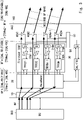
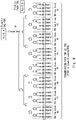
- Fig. 4 illustrates a connection configuration example of the entire transmission path from the point A to each point B
- Fig. 5 illustrates an enlarged configuration example of a TRX sub-block #1 of Fig. 4 .
- the distribution synthesis unit 60 arranged in the transmission path from the point A to each point B is composed of a plurality of distribution synthesizer 61 connected in a tournament mode.
- the uppermost stage of the tournament is the point A
- the lowermost stage is each point B.
- the UL calibration signals can be transmitted from the calibration transmitter-receiver CAL-TRX to each receiver RX#n collectively and simultaneously.
- the DL calibration signals can be transmitted from each transmitter TX#n to the calibration transmitter-receiver CAL-TRX collectively and simultaneously.
- the DL calibration when DL calibration signals are transmitted from the transmitters TX#n to the calibration transmitter-receiver CAL-TRX, the DL calibration signals sent from the transmitters TX#n are synthesized by the distribution synthesis unit 60. Therefore, when each transmitter TX#n uses DL calibration signals having the same frequency arrangement composed of multi-tones, the DL calibration signals interfere with each other. In order to avoid such interference between the DL calibration signals, it is also conceivable to individually perform DL calibration for each transmitter TX#n in a different time zone. However, when the DL calibration is performed individually for each transmitter TX#n, it takes time to complete the DL calibration of each transmitter TX#n. As a result, the amplitude and phase specifications of each transmitter TX#n fluctuate within that time, and thus accuracy of DL calibration deteriorates.
- the AAS 100 performs DL calibration under the Fifth Generation (5G) New Radio (NR) standard established by the Third Generation Partnership Project (3GPP), it is necessary to perform the DL calibration at a very short free time at the head or the tail of a UL symbol or a DL symbol.
- 5G Fifth Generation
- NR New Radio
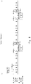
- Fig. 6 is a diagram explaining an example of a timing at which the AAS 100 performs DL calibration under the 5G NR standard.
- SC subcarriers
- a very short free time (denoted as "DC” in the drawing) of 8.34 [ ⁇ sec] at the head of the DL symbol (denoted as "D” in the drawing) is allocated as a time for executing the DL calibration (i.e., a time for executing the DL calibration operation of Fig. 2 described above).
- the DL operation in Fig. 3 described above is executed at the time when the DL symbol is allocated.
- the UL operation is executed at a time when the UL symbol (denoted as "U" in the figure) is allocated.
- an amplitude phase state of the transmitter TX#1 for which the DL calibration correction value is acquired at the beginning of a calibration cycle may change at a time when derivation of the DL calibration correction value of the last transmitter TX#m is terminated.
- a deviation occurs in the amplitude phase after performing the calibration of the transmitter TX#1 at the beginning of the same cycle, a problem arises that a residual amplitude phase error after the DL calibration of all the transmitters TX#1 to TX#m deteriorates.
- the baseband unit 20 causes the DL calibration signal composed of multi-tones, which is sent from each transmitter TX#n, to be orthogonalized in frequency for each transmitter TX#n.
- Fig. 7 is a diagram explaining a first example of the frequency arrangement of the DL calibration signal for each transmitter TX#n.
- subcarriers used for sending out the DL calibration signal are arranged at intervals of X [MHz].
- the frequency arrangements of the DL calibration signals are caused to shift by Y [MHz] in a frequency direction. It is noted that fs0 [MHz] is a reference frequency.
- Frequency arrangement condition A1 X MHz > Y MHz ⁇ number of transmitters TX # n - 1 is established .
- the frequency arrangements of the DL calibration signals are caused to shift by Y [MHz] in the frequency direction.
- the frequency arrangements of the DL calibration signals are caused to shift in such a way as to deviate by Y [MHz] or more.
- Fig. 9 is a diagram explaining a second example of the frequency arrangement of the DL calibration signal of each transmitter TX#n.
- the frequency arrangements of the DL calibration signals are caused to shift by deviating by Y [MHz] or more in the frequency direction.
- the frequency arrangement of the transmitter TX#2 is caused to shift in a positive frequency direction by fs1 - fs0 (>Y) [MHz] with respect to the frequency arrangement of the transmitter TX#1.
- fs0 [MHz] is a frequency serving as a reference of the transmitter TX#n in which n is an odd number
- fs1 [MHz] is a frequency serving as a reference of the transmitter TX#n in which n is an even number.
- the frequency arrangement of the transmitter TX#3 is caused to shift in a negative frequency direction by fs1 - fs0 - Y (>Y) [MHz] with respect to the frequency arrangement of the transmitter TX#2. Therefore, the frequency separation of the DL calibration signals between the transmitters TX#2 and TX#3 can be ensured.
- a shift amount of the frequency arrangement of the DL calibration signals between the adjacent transmitters TX#n may be optionally determined. For example, a shift amount which is not affected by mutual coupling may be acquired in advance, and the frequency arrangement may be caused to shift to the shift amount or more.
- the baseband unit 20 causes the DL calibration signal sent from each transmitter TX#n to be orthogonalized in frequency for each transmitter TX#n. Therefore, even when the DL calibration signals are transmitted from the transmitters TX#n to the calibration transmitter-receiver CAL-TRX collectively and simultaneously, mixing and interference of the DL calibration signals on the frequency axis can be avoided.
- DL calibration of each transmitter TX#n can be performed collectively and simultaneously. Therefore, in order to perform DL calibration in a very short free time at the head or the tail of a UL symbol or a DL symbol under the 5G NR standard, it is effective to perform DL calibration of each transmitter TX#n collectively and simultaneously as in the first example embodiment.
- the spatial multiplexing performance (achievement of null depth, increase in the number of spatial multiplexing, etc.) when performing MU-MIMO depends greatly on the accuracy of DL calibration. Therefore, maintaining the accuracy of DL calibration as in the first example embodiment is effective in improving the spatial multiplexing performance when performing MU-MIMO.
- the DL calibration according to the first example embodiment makes it possible not only to correct a variation in amplitude and phase characteristics of each transmitter TX#n but also to compensate an absolute value of output power of each transmitter TX#n, it is possible to further stabilize a transmission level of each transmitter TX#n.
- a method of stabilizing absolute values of output powers of all the transmitters TX#1 to TX#m using the DL calibration function described above can be achieved by performing weighting correction on an absolute output level of each of the transmitters TX#n in such a way as to match an absolute output level of the transmitter other than the representative transmitter to an absolute output level of the transmitter TX#1 as a representative transmitter.
- weighting correction can be performed on the absolute output level of each transmitter TX#n in such a way as to match the absolute output level of each transmitter TX#n to the average value of the absolute output levels of all the transmitters TX#1 to TX#m.
- the baseband unit 20 causes the DL calibration signal sent from each transmitter TX#n to be orthogonalized in frequency for each transmitter TX#n. As a result, even when the DL calibration signals are transmitted from each transmitter TX#n to the calibration transmitter-receiver CAL-TRX collectively and simultaneously, mixing and interference between the DL calibration signals on the frequency axis can be avoided.
- the DL calibration signal passes through each transmitter TX#n or a calibration receiver CAL-RX, in a case where a peak to average power ratio (PAPR) of the DL calibration signal is high, the DL calibration signal may be affected by a nonlinearity of the transmitter TX#n or CAL-RX. As a result, the DL calibration signal may suffer distortion degradation due to AM-AM degradation to amplitude or AM-PM degradation to phase (where AM means amplitude modulation and PM means phase modulation).
- AM means amplitude modulation
- PM means phase modulation
- the baseband unit 20 applies phase modulation to the phase of each subcarrier used for sending out the DL calibration signal for each transmitter TX#n.
- the phase modulation may be, for example, phase modulation by a Zadoff-Chu (ZC) sequence, phase modulation by quadrature phase shift keying (QPSK), or quadrature amplitude modulation (QAM) in which phase modulation and amplitude modulation are combined may be used.
- ZC Zadoff-Chu
- QPSK quadrature phase shift keying
- QAM quadrature amplitude modulation
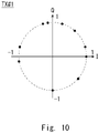
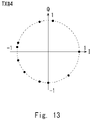
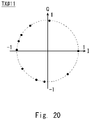
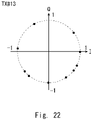
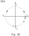
- each transmitter TX#n uses 10 subcarriers for sending out the DL calibration signal, and for each transmitter TX#n, phase modulation by a Zadoff-Chu sequence is applied to the phase of each of the 10 subcarriers.
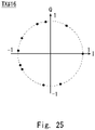
- a constellation of DL calibration signals subjected to phase modulation by the Zadoff-Chu sequence an example of a constellation of DL calibration signals for transmitters TX#1 to TX#16 are representatively illustrated in each of Figs. 10 to 25 .
- the horizontal axis represents PAPR [dB]
- the vertical axis represents a complementary cumulative distribution function (CCDF) [%].
- CCDF represents a probability that PAPR being the value on the horizontal axis occurs with respect to the DL calibration time signal.
- PAPR characteristics of two types of DL calibration signals are illustrated as the PAPR characteristics of the DL calibration signals from one transmitter TX#n that have passed through the point B in Fig. 1 .
- the first type is a PAPR characteristic of a DL calibration signal (denoted as "ZC-OFDM, 1TX” in the figure) subjected to phase modulation by a Zadoff-Chu sequence.
- the second type is a PAPR characteristic of a DL calibration signal (denoted as "QPSK-OFDM, 1TX” in the figure) subjected to phase modulation by QPSK.
- the PAPR of the DL calibration signal is suppressed by applying the phase modulation.
- PAPR is suppressed in the DL calibration signal subjected to phase modulation by the Zadoff-Chu sequence, compared with the DL calibration signal subjected to phase modulation by QPSK.
- PAPR characteristics of three kinds of synthesized signals are illustrated as PAPR characteristics of synthesized signals in which DL calibration signals from 32 transmitters TX#n passing through the point A in Fig. 1 are synthesized.
- the first type is a PAPR characteristic of a synthesized signal (denoted as "the same CAL signal, 32TX" in the figure) of the DL calibration signals from the 32 transmitters TX#n when the DL calibration signals are all arranged at the same frequency.
- the second type is a PAPR characteristic of a synthesized signal (denoted as "ZC-OFDM, 32TX” in the figure) of DL calibration signals from the 32 transmitters TX#n when the DL calibration signals are orthogonalized in frequency and subjected to phase modulation by a Zadoff-Chu sequence.
- the third type is a PAPR characteristic of a synthesized signal (denoted as "QPSK-OFDM, 32TX” in the figure) of the DL calibration signals from the 32 transmitters TX#n when the DL calibration signals are orthogonalized in frequency and subjected to phase modulation by QPSK.
- the PAPR is suppressed in the synthesized signal of the DL calibration signals subjected to the phase modulation by the Zadoff-Chu sequence, compared to the synthesized signal of the DL calibration signals subjected to the phase modulation by the QPSK, similarly to the DL calibration signal passing through the point B. Accordingly, the DL calibration signal subjected to the phase modulation by the Zadoff-Chu sequence can reduce a distortion influence on the DL calibration signal more than the DL calibration signal subjected to the phase modulation by the QPSK.
- the baseband unit 20 applies phase modulation to the phase of each subcarrier used by each transmitter TX#n for sending out the DL calibration signal for each transmitter TX#n.
- Fig. 27 is a diagram illustrating a configuration example of the wireless communication device 500 conceptually illustrating the first and second example embodiments described above.
- the transmitter-receiver TRX#n is associated to the transmitter-receiver TRX#n illustrated in Fig. 1 .
- the transmitter-receiver TRX#n includes a transmitter TX#n and a receiver RX#n.
- the control unit 510 is associated to the baseband unit 20 illustrated in Fig. 1 , and performs control related to transmission calibration (DL calibration).
- control unit 510 causes the transmission calibration signal to be sent to each transmitter TX#n to be orthogonalized in frequency for each transmitter TX#n.
- the control unit 510 may arrange the frequency arrangement of the transmission calibration signal of each transmitter TX#n by arranging subcarriers used for sending out the transmission calibration signal at predetermined intervals.
- the control unit 510 may cause the frequency arrangement of the transmission calibration signal of a transmitter (transmitter TX#n-1 or transmitter TX#n+1) adjacent to one transmitter TX#n to shift in a frequency direction from the frequency arrangement of the transmission calibration signal of the one transmitter TX#n.
- the control unit 510 may cause the frequency arrangement of the transmission calibration signal of the transmitter (transmitter TX#n-1 or transmitter TX#n+1) adjacent to one transmitter TX#n to shift by a predetermined shift amount or more in the frequency direction from the frequency arrangement of the transmission calibration signal of the transmitter TX#n.
- Each transmitter TX#n sends a transmission calibration signal that is orthogonalized in frequency. It is noted that each transmitter TX#n may simultaneously send transmission calibration signals that are orthogonalized in frequency.
- the distribution synthesis unit 530 is associated to the distribution synthesis unit 60 illustrated in Fig. 1 .
- the distribution synthesis unit 530 synthesizes the transmission calibration signals transmitted from the transmitters TX#n, and transmits the synthesized signal to the calibration receiver CAL-RX in the calibration transmitter-receiver CAL-TRX.
- the calibration transmitter-receiver CAL-TRX is associated to the calibration transmitter-receiver CAL-TRX illustrated in Fig. 1 .
- the calibration receiver CAL-RX sends the synthesized signal transmitted from the distribution synthesis unit 530 to the control unit 510.
- the control unit 510 calculates a transmission calibration weight for compensating for variations in amplitude and phase characteristics of each transmitter TX#n, based on the synthesized signal sent from the calibration transmitter-receiver CAL-TRX.
- control unit 510 may apply phase modulation to the phase of the subcarrier used by each transmitter TX#n for sending out the transmission calibration signal for each transmitter TX#n.
- the phase modulation may be a phase modulation by a Zadoff-Chu sequence, a phase modulation by QPSK, or an amplitude phase modulation by QAM.
- the configuration in which 32 transmitter-receivers are provided has been described as an example, but the number of transmitter-receivers is not limited to 32.
- the number of transmitter-receivers may be greater than 32 or less than 32.
- the AAS according to the present disclosure is used for a base station, but the present disclosure is not limited thereto.
- the AAS according to the present disclosure can be used for optional wireless communication device other than a base station.
- the AAS according to the present disclosure has been described as a hardware configuration, but the present disclosure is not limited thereto. According to the present disclosure, optional processing of the ASS can also be achieved by causing a processor such as a central processing unit (CPU) to execute a computer program.
- a processor such as a central processing unit (CPU) to execute a computer program.
- Non-transitory computer readable media include various types of tangible storage media.
- Examples of the non-transitory computer readable media include magnetic recording media (e.g., flexible disk, magnetic tape, hard disk drive), magneto-optical recording media (e.g., magneto-optical disk), compact disc-read only memory (CD-ROM), CD-recordable (CD-R), CD-rewritable (CD-R/W), semiconductor memory (e.g., mask ROM, programmable ROM (PROM), erasable PROM (EPROM), flash ROM, and random access memory (RAM)).
- magnetic recording media e.g., flexible disk, magnetic tape, hard disk drive
- magneto-optical recording media e.g., magneto-optical disk
- CD-ROM compact disc-read only memory
- CD-R CD-recordable
- CD-R/W CD-rewritable
- semiconductor memory e.g., mask ROM, programmable ROM (PROM), erasable PROM
- the program may also be supplied to a computer by various types of transitory computer readable media.
- Examples of the transitory computer-readable media include electrical signals, optical signals, and electromagnetic waves.
- the transitory computer-readable media are able to provide the program to the computer via wired communication paths, such as electrical wires and optical fibers, or wireless communication paths.
- a wireless communication device comprising:
- control unit arranges a frequency arrangement of the transmission calibration signal of each transmitter by arranging subcarriers being used by each transmitter for sending out the transmission calibration signal at predetermined intervals, and causes a frequency arrangement of the transmission calibration signal of a transmitter adjacent to one transmitter to shift in a frequency direction from a frequency arrangement of the transmission calibration signal of the one transmitter.
- control unit causes a frequency arrangement of the transmission calibration signal of a transmitter adjacent to the one transmitter to shift in a frequency direction from a frequency arrangement of the transmission calibration signal of the one transmitter by a predetermined shift amount or more.
- control unit applies phase modulation to a phase of a subcarrier being used by each transmitter for sending out the transmission calibration signal, for each transmitter.
- phase modulation is phase modulation by a Zadoff-Chu sequence, phase modulation by quadrature phase shift keying (QPSK), or amplitude-phase modulation by quadrature amplitude modulation (QAM).
- QPSK quadrature phase shift keying
- QAM amplitude-phase modulation by quadrature amplitude modulation
- a frequency arrangement of the transmission calibration signal of each transmitter is a frequency arrangement in which subcarriers being used by each transmitter for sending out the transmission calibration signal are arranged at predetermined intervals, and a frequency arrangement of the transmission calibration signal of a transmitter adjacent to one transmitter is caused to shift in a frequency direction from a frequency arrangement of the transmission calibration signal of the one transmitter.
- a frequency arrangement of the transmission calibration signal of a transmitter adjacent to the one transmitter is caused to shift in a frequency direction from a frequency arrangement of the transmission calibration signal of the one transmitter by a predetermined shift amount or more.
- the wireless communication method according to any one of Supplementary Notes 6 to 8, further comprising a fourth step of applying phase modulation to a phase of a subcarrier being used by each transmitter for sending out the transmission calibration signal, for each transmitter.
- phase modulation is phase modulation by a Zadoff-Chu sequence, phase modulation by quadrature phase shift keying (QPSK), or amplitude-phase modulation by quadrature amplitude modulation (QAM).
- QPSK quadrature phase shift keying
- QAM amplitude-phase modulation by quadrature amplitude modulation
Landscapes
- Engineering & Computer Science (AREA)
- Computer Networks & Wireless Communication (AREA)
- Signal Processing (AREA)
- Physics & Mathematics (AREA)
- Electromagnetism (AREA)
- Radio Transmission System (AREA)
- Variable-Direction Aerials And Aerial Arrays (AREA)
Applications Claiming Priority (2)
| Application Number | Priority Date | Filing Date | Title |
|---|---|---|---|
| JP2019141082 | 2019-07-31 | ||
| PCT/JP2020/020714 WO2021019885A1 (ja) | 2019-07-31 | 2020-05-26 | 無線通信装置及び無線通信方法 |
Publications (2)
| Publication Number | Publication Date |
|---|---|
| EP4007069A1 true EP4007069A1 (de) | 2022-06-01 |
| EP4007069A4 EP4007069A4 (de) | 2023-01-25 |
Family
ID=74230667
Family Applications (1)
| Application Number | Title | Priority Date | Filing Date |
|---|---|---|---|
| EP20848545.8A Pending EP4007069A4 (de) | 2019-07-31 | 2020-05-26 | Drahtloskommunikationsvorrichtung und -verfahren |
Country Status (4)
| Country | Link |
|---|---|
| US (1) | US11990683B2 (de) |
| EP (1) | EP4007069A4 (de) |
| JP (1) | JP7497892B2 (de) |
| WO (1) | WO2021019885A1 (de) |
Families Citing this family (1)
| Publication number | Priority date | Publication date | Assignee | Title |
|---|---|---|---|---|
| JP7753854B2 (ja) | 2021-12-14 | 2025-10-15 | 日本電気株式会社 | アクティブ・アンテナ・システム及びその方法 |
Family Cites Families (21)
| Publication number | Priority date | Publication date | Assignee | Title |
|---|---|---|---|---|
| EP1178562A1 (de) * | 2000-08-03 | 2002-02-06 | Telefonaktiebolaget L M Ericsson (Publ) | Kalibrierung einer Gruppenantenne |
| JP2003218621A (ja) * | 2002-01-21 | 2003-07-31 | Nec Corp | アレーアンテナの校正装置及び校正方法 |
| JP4252573B2 (ja) * | 2003-06-02 | 2009-04-08 | 富士通株式会社 | アレーアンテナ通信装置およびアレーアンテナ通信装置のキャリブレーション方法 |
| DE602004029906D1 (de) * | 2003-08-27 | 2010-12-16 | Wavion Ltd | Wlan-kapazitäts-erweiterung durch verwendung von sdm |
| JP2006279900A (ja) * | 2005-03-30 | 2006-10-12 | Kyocera Corp | 通信装置及びキャリブレーション方法 |
| US7215298B1 (en) * | 2005-09-06 | 2007-05-08 | Lockheed Martin Corporation | Extendable/retractable antenna calibration element |
| US20080129613A1 (en) * | 2006-12-05 | 2008-06-05 | Nokia Corporation | Calibration for re-configurable active antennas |
| FI20065841A0 (fi) * | 2006-12-21 | 2006-12-21 | Nokia Corp | Kommunikointimenetelmä ja -järjestelmä |
| US8953562B2 (en) * | 2007-02-01 | 2015-02-10 | Alcatel Lucent | Method of using uplink reference signals for access grant requests |
| JP5725703B2 (ja) | 2009-11-13 | 2015-05-27 | 三菱電機株式会社 | アレーアンテナの校正装置および校正方法 |
| US9780447B2 (en) * | 2012-01-24 | 2017-10-03 | Commscope Technologies Llc | Multi-element antenna calibration technique |
| US9735899B2 (en) * | 2013-09-30 | 2017-08-15 | Vayyar Imaging Ltd. | Device and method for calibrating antenna array systems |
| US9386606B2 (en) * | 2014-09-03 | 2016-07-05 | Motorola Solutions, Inc. | Methods and systems for embedding supplementary data channel in LTE-based communication systems |
| WO2016129674A1 (ja) | 2015-02-13 | 2016-08-18 | 伊東電機株式会社 | 植物栽培装置及び植物栽培システム |
| CN111132362B (zh) | 2015-09-02 | 2024-06-28 | 华为技术有限公司 | 一种物联网通信方法、网络侧设备及物联网终端 |
| JP2017195463A (ja) | 2016-04-19 | 2017-10-26 | 住友電気工業株式会社 | アクティブアンテナシステム |
| JP7156399B2 (ja) * | 2019-01-11 | 2022-10-19 | 日本電気株式会社 | 制御装置及び無線通信装置 |
| JP7511094B2 (ja) * | 2021-03-16 | 2024-07-04 | エーエスティー アンド サイエンス エルエルシー | 相互結合に基づくキャリブレーション |
| TWI796828B (zh) * | 2021-11-10 | 2023-03-21 | 財團法人工業技術研究院 | 天線陣列校正裝置與其方法 |
| FR3129787B1 (fr) * | 2021-12-01 | 2025-02-21 | Commissariat Energie Atomique | Système antennaire à rayonnement contrôlé |
| US12580308B2 (en) * | 2022-02-25 | 2026-03-17 | Bdcm A2 Llc | Beamformer RFIC calibration method therefor |
-
2020
- 2020-05-26 EP EP20848545.8A patent/EP4007069A4/de active Pending
- 2020-05-26 WO PCT/JP2020/020714 patent/WO2021019885A1/ja not_active Ceased
- 2020-05-26 JP JP2021536628A patent/JP7497892B2/ja active Active
- 2020-05-26 US US17/628,314 patent/US11990683B2/en active Active
Also Published As
| Publication number | Publication date |
|---|---|
| EP4007069A4 (de) | 2023-01-25 |
| US20220285853A1 (en) | 2022-09-08 |
| US11990683B2 (en) | 2024-05-21 |
| JP7497892B2 (ja) | 2024-06-11 |
| JPWO2021019885A1 (de) | 2021-02-04 |
| WO2021019885A1 (ja) | 2021-02-04 |
Similar Documents
| Publication | Publication Date | Title |
|---|---|---|
| US10256894B2 (en) | Hybrid beam former | |
| US8958412B2 (en) | Methods and apparatus for uplink timing alignment in system with large number of antennas | |
| US8526537B2 (en) | Digital pre-distortion processing method and apparatus | |
| KR102059138B1 (ko) | 포락선 추적 보정 장치 및 방법 | |
| US8923374B2 (en) | Method and arrangement of delay calibration for orthogonal frequency division multiplexing (OFDM) system | |
| US9819407B2 (en) | Pre-compensation of the phase shifting error | |
| US10541760B2 (en) | Radio communication apparatus and antenna calibration method | |
| US12592730B2 (en) | Signal processing device, signal processing method, and non-transitory computer readable medium for a distortion compensation circuit | |
| US11456762B2 (en) | Control device and radio communication device | |
| US11990683B2 (en) | Wireless communication device and wireless communication method | |
| US9866288B2 (en) | Method for operating a base station comprising a plurality of antennas in a wireless radio network | |
| EP2896175B1 (de) | Übertragung in einem nullraum einer vorgegebenen frequenz | |
| US10944489B2 (en) | Active antenna system, communication device, calibration method of active antenna system and recording medium | |
| US9991994B1 (en) | Method and terminal device for reducing image distortion | |
| KR102945140B1 (ko) | 상향링크 신호 교정 방법 및 장치 | |
| JP2006319412A (ja) | 無線受信装置、及び無線送信装置 | |
| US20160323126A1 (en) | Wireless device and data transfer method | |
| US12456994B2 (en) | Signal processing device, signal processing method, and non-transitory computer readable medium | |
| US12526059B2 (en) | Signal processing apparatus, radio communication apparatus, signal processing method, and non-transitory computer readable medium on which program is stored | |
| EP2706714A1 (de) | Signalverarbeitungsvorrichtung und Verfahren zur Verarbeitung von mindestens zwei Eingangssignalen für einen Sender einer Kommunikationsvorrichtung | |
| CN115134197B (zh) | 信道补偿方法及系统、用户设备、基站及存储介质 | |
| CN117713844A (zh) | 无线通信装置和无线通信装置的操作方法 | |
| WO2010082333A1 (ja) | 無線基地局装置及び遅延補正方法 | |
| KR20160031404A (ko) | 빔 공간 mimo에서 기저대역 신호 변조 방법 및 장치 |
Legal Events
| Date | Code | Title | Description |
|---|---|---|---|
| STAA | Information on the status of an ep patent application or granted ep patent |
Free format text: STATUS: THE INTERNATIONAL PUBLICATION HAS BEEN MADE |
|
| PUAI | Public reference made under article 153(3) epc to a published international application that has entered the european phase |
Free format text: ORIGINAL CODE: 0009012 |
|
| STAA | Information on the status of an ep patent application or granted ep patent |
Free format text: STATUS: REQUEST FOR EXAMINATION WAS MADE |
|
| 17P | Request for examination filed |
Effective date: 20220121 |
|
| AK | Designated contracting states |
Kind code of ref document: A1 Designated state(s): AL AT BE BG CH CY CZ DE DK EE ES FI FR GB GR HR HU IE IS IT LI LT LU LV MC MK MT NL NO PL PT RO RS SE SI SK SM TR |
|
| RIC1 | Information provided on ipc code assigned before grant |
Ipc: H04B 7/06 20060101ALI20220920BHEP Ipc: H01Q 21/06 20060101ALI20220920BHEP Ipc: H01Q 3/26 20060101ALI20220920BHEP Ipc: H04B 1/04 20060101AFI20220920BHEP |
|
| DAV | Request for validation of the european patent (deleted) | ||
| DAX | Request for extension of the european patent (deleted) | ||
| REG | Reference to a national code |
Ref country code: DE Ref legal event code: R079 Free format text: PREVIOUS MAIN CLASS: H01Q0003260000 Ipc: H04B0001040000 |
|
| A4 | Supplementary search report drawn up and despatched |
Effective date: 20230103 |
|
| RIC1 | Information provided on ipc code assigned before grant |
Ipc: H04B 7/06 20060101ALI20221221BHEP Ipc: H01Q 21/06 20060101ALI20221221BHEP Ipc: H01Q 3/26 20060101ALI20221221BHEP Ipc: H04B 1/04 20060101AFI20221221BHEP |
|
| STAA | Information on the status of an ep patent application or granted ep patent |
Free format text: STATUS: EXAMINATION IS IN PROGRESS |
|
| 17Q | First examination report despatched |
Effective date: 20241217 |