EP4007073A1 - Elektrische leiter und elektrische anschlussanordnung, die einen solchen elektrischen leiter umfasst - Google Patents
Elektrische leiter und elektrische anschlussanordnung, die einen solchen elektrischen leiter umfasst Download PDFInfo
- Publication number
- EP4007073A1 EP4007073A1 EP21210517.5A EP21210517A EP4007073A1 EP 4007073 A1 EP4007073 A1 EP 4007073A1 EP 21210517 A EP21210517 A EP 21210517A EP 4007073 A1 EP4007073 A1 EP 4007073A1
- Authority
- EP
- European Patent Office
- Prior art keywords
- electrical
- fixing
- fixing grooves
- electrical conductor
- conductors
- Prior art date
- Legal status (The legal status is an assumption and is not a legal conclusion. Google has not performed a legal analysis and makes no representation as to the accuracy of the status listed.)
- Withdrawn
Links
Images




Classifications
-
- H—ELECTRICITY
- H02—GENERATION; CONVERSION OR DISTRIBUTION OF ELECTRIC POWER
- H02B—BOARDS, SUBSTATIONS OR SWITCHING ARRANGEMENTS FOR THE SUPPLY OR DISTRIBUTION OF ELECTRIC POWER
- H02B1/00—Frameworks, boards, panels, desks, casings; Details of substations or switching arrangements
- H02B1/20—Bus-bar or other wiring layouts, e.g. in cubicles, in switchyards
-
- H—ELECTRICITY
- H01—ELECTRIC ELEMENTS
- H01R—ELECTRICALLY-CONDUCTIVE CONNECTIONS; STRUCTURAL ASSOCIATIONS OF A PLURALITY OF MUTUALLY-INSULATED ELECTRICAL CONNECTING ELEMENTS; COUPLING DEVICES; CURRENT COLLECTORS
- H01R25/00—Coupling parts adapted for simultaneous co-operation with two or more identical counterparts, e.g. for distributing energy to two or more circuits
- H01R25/14—Rails or bus-bars constructed so that the counterparts can be connected thereto at any point along their length
-
- H—ELECTRICITY
- H01—ELECTRIC ELEMENTS
- H01R—ELECTRICALLY-CONDUCTIVE CONNECTIONS; STRUCTURAL ASSOCIATIONS OF A PLURALITY OF MUTUALLY-INSULATED ELECTRICAL CONNECTING ELEMENTS; COUPLING DEVICES; CURRENT COLLECTORS
- H01R4/00—Electrically-conductive connections between two or more conductive members in direct contact, i.e. touching one another; Means for effecting or maintaining such contact; Electrically-conductive connections having two or more spaced connecting locations for conductors and using contact members penetrating insulation
- H01R4/28—Clamped connections, spring connections
- H01R4/30—Clamped connections, spring connections utilising a screw or nut clamping member
- H01R4/305—Clamped connections, spring connections utilising a screw or nut clamping member having means for facilitating engagement of conductive member or for holding it in position
-
- H—ELECTRICITY
- H01—ELECTRIC ELEMENTS
- H01R—ELECTRICALLY-CONDUCTIVE CONNECTIONS; STRUCTURAL ASSOCIATIONS OF A PLURALITY OF MUTUALLY-INSULATED ELECTRICAL CONNECTING ELEMENTS; COUPLING DEVICES; CURRENT COLLECTORS
- H01R4/00—Electrically-conductive connections between two or more conductive members in direct contact, i.e. touching one another; Means for effecting or maintaining such contact; Electrically-conductive connections having two or more spaced connecting locations for conductors and using contact members penetrating insulation
- H01R4/28—Clamped connections, spring connections
- H01R4/30—Clamped connections, spring connections utilising a screw or nut clamping member
- H01R4/34—Conductive members located under head of screw
-
- H—ELECTRICITY
- H02—GENERATION; CONVERSION OR DISTRIBUTION OF ELECTRIC POWER
- H02B—BOARDS, SUBSTATIONS OR SWITCHING ARRANGEMENTS FOR THE SUPPLY OR DISTRIBUTION OF ELECTRIC POWER
- H02B1/00—Frameworks, boards, panels, desks, casings; Details of substations or switching arrangements
- H02B1/01—Frameworks
- H02B1/014—Corner connections for frameworks
-
- H—ELECTRICITY
- H02—GENERATION; CONVERSION OR DISTRIBUTION OF ELECTRIC POWER
- H02G—INSTALLATION OF ELECTRIC CABLES OR LINES, OR OF COMBINED OPTICAL AND ELECTRIC CABLES OR LINES
- H02G5/00—Installations of bus-bars
-
- H—ELECTRICITY
- H02—GENERATION; CONVERSION OR DISTRIBUTION OF ELECTRIC POWER
- H02G—INSTALLATION OF ELECTRIC CABLES OR LINES, OR OF COMBINED OPTICAL AND ELECTRIC CABLES OR LINES
- H02G5/00—Installations of bus-bars
- H02G5/02—Open installations
-
- H—ELECTRICITY
- H01—ELECTRIC ELEMENTS
- H01R—ELECTRICALLY-CONDUCTIVE CONNECTIONS; STRUCTURAL ASSOCIATIONS OF A PLURALITY OF MUTUALLY-INSULATED ELECTRICAL CONNECTING ELEMENTS; COUPLING DEVICES; CURRENT COLLECTORS
- H01R13/00—Details of coupling devices of the kinds covered by groups H01R12/70 or H01R24/00 - H01R33/00
- H01R13/02—Contact members
- H01R13/03—Contact members characterised by the material, e.g. plating, or coating materials
Definitions
- the present disclosure relates to the distribution of electricity and relates in particular to electrical connectors which can be used in an electricity distribution board.
- busbars in English
- connection bars make it possible to distribute and distribute electricity between several devices and/or groups of conductors thanks to connections made in electrical cabinets or electrical panels.
- connection bar arrangement in an electrical cubicle.
- the bars are made of copper and are interconnected by means of mechanical devices. Such connection bars have long been satisfactory.
- connection devices having increased performance, for example to operate with high current ratings, in particular greater than or equal to 5000 A or 6300 A, while being less expensive to manufacture.
- the invention relates to an electrical connection assembly comprising a plurality of electrical conductors as previously described, at least one connection plate and at least one fixing element, the connection plate being associated with at least two conductors electrical to connect them electrically with each other, said at least one fixing element being associated with the connection plate and being at least partially received in a corresponding groove of at least one of the electrical conductors.
- the invention relates to an electricity distribution installation comprising an armature, an electrical connection assembly as described above and at least one electrical device connected to at least some of the conductors of the connection assembly.
- the figure 1 represents an electricity distribution installation 1, such as an electrical cabinet or an electrical panel.
- the installation 1 comprises a plurality of electrical conductors 2, or connection bars, which are preferably arranged in a frame 4 which is here placed or fixed on the ground 6.
- a first group 8 of electrical conductors 2 is arranged horizontally, while a second group 10 of electrical conductors 2 is arranged vertically.
- each electrical phase (as well as the neutral, if applicable) can be associated with a conductor 2 .
- connection plates 14 made of metal, which are held pressed against the corresponding conductors 2 by means of fixing elements 16, such as screws, or fishplates, or any other suitable mechanical element, which cooperate with grooves 18 provided along the conductors 2.
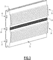
- the figure 2 and 3 represent a portion of an electrical conductor 2, seen from two different angles.
- the conductor 2 comprises a metallic body 20 made of aluminum having the shape of a bar and extending along a longitudinal axis, denoted X2 on the figure 2 .
- the cross section 22 of the body 20 has a parallelepipedal or substantially parallelepipedal shape.
- the conductor 2 has the shape of a flat bar.
- the cross section 22 of the body 20 is greater than or equal to 9000mm 2 , or preferably greater than or equal to 9600mm 2 .
- the body 20 is obtained by an extrusion process.
- the conductor 2 comprises a main front face, designated "23" in what follows, and a rear main face.
- the main faces here are the faces which are parallel to the axis X2, which are perpendicular to the cross sections 22, and which have the largest areas.
- the conductor 2 comprises a plurality of fixing grooves 24 formed on a main face of the metal body, here on the front face 23.
- the fixing grooves 24 extend parallel to the longitudinal axis X2.
- one of the fixing grooves 24 is arranged in the center of said main face 23, along the axis X2.
- the other fixing grooves 24 are arranged symmetrically on either side of the central fixing groove, on the same face of the body 20, parallel to the axis X2.
- the grooves 24 have a rectilinear shape.
- Each of the grooves 24 is extended inside the body 20 by a recess 26 which here has the shape of a trench or mushroom.
- the recess 26 extends straight under each groove 24 along the conductor 2.
- the recess 26 is configured to receive a head of a screw or, more generally, a retaining portion of an element. fixing 16.
- the conductor 2 has three grooves: a central groove and two lateral grooves, each arranged on one side of the central groove.
- This arrangement makes it possible to circulate, for a single conductor 2, electric currents of high intensity, for example of intensity which can range up to 6300 A.
- the symmetrical arrangement of the grooves 24 makes it possible to ensure a uniform distribution of the electric current in the conductor 2, and to improve heat dissipation and to balance the heating points present at the level of the interconnections and the points of contact with the plates. 14 and/or with fixing elements 16.
- the conductor 2 does not have a preferential mounting direction, which facilitates the assembly of the conductors 2 with other elements, for example to form the installation 1.
- the establishment of the fixing elements 16 is carried out without additional operation in the conductor 2 (such as a drilling) in front face by the recess 26, the latter forming a continuous clamping line in the conductor 2.
- the conductor 2 comprises electrical contact tracks 28 which are arranged in pairs parallel to the side edges of each fixing groove 24.
- the contact tracks 28 are made of an electrically conductive material different from the material used to form the body.
- metal conductor 2 here, aluminum
- the contact tracks 28 are made of copper, although alternatively it is possible to use another metallic material, for example a copper alloy such as bronze or brass, or tin, or nickel, or silver, or an alloy of these materials, or any other suitable material.
- conductor 2 has a hybrid construction, using two different electrically conductive materials.
- contact tracks 28 are arranged on the body 2 and in particular on the main face 23. In other words, the contact tracks 28 cover part of the surface of the metallic body of the conductor 2. Alternatively, grooves 24 and contact tracks 28 could also be provided on the opposite face
- Each groove 24 is associated with two tracks 28.
- tracks 28 have identical dimensions.
- the tracks 28 associated with each groove 24 are arranged symmetrically on either side of said groove 24.
- the contact tracks 28 make it possible to ensure good electrical connectivity with the fixing elements 16 and/or with the fixing plates 14.
- each contact track 28 is less than or equal to 500 microns.
- the material used to form the contact tracks is deposited by a thermal spraying process.
- fixing teeth 30 are formed on the side edges 32 of body 20.
- fixing teeth 30 extend along body 20, parallel to axis X2.
- the body 20 comprises cooling fins 36, 38 arranged on a rear face 34 opposite the main face 23 on which the fixing grooves 24 are formed.
- the cooling fins 36, 38 are aligned parallel to the direction longitudinal X2.
- cooling fins 36 of a first type are arranged laterally on either side of a central part of the rear face 34.
- Cooling fins 38 of a second type are arranged along the part center of the rear face 34.
- the cooling fins 38 of the second type are for example smaller than the cooling fins 36 of the first type.
- the fins 36 and 38 significantly increase the exchange perimeter of the conductor 2 with the surrounding air and make it possible to dissipate the heat resulting from the circulation of the electric current (Joule effect) in the conductor 2.
- the body 20 may include a surface treatment such as painting or anodizing (colorless or not) to promote heat exchange by radiation.
- a surface treatment such as painting or anodizing (colorless or not) to promote heat exchange by radiation.
- connection elements without however needing to use a conductor made entirely of copper, since this would increase the manufacturing cost of the conductor, and this would increase its weight and its size.
- Conductor 2 can be easily dimensioned so that its rating in electric current corresponds to the standardized ratings used by electrical and electrotechnical devices (for example, 1000 A, 1600 A, 2000 A, 3200 A, 4000 A, 5000 A, 6300 A) .
- This is not the case with copper bars, which are generally available on the market with only predefined dimensions, which means that the gauge obtained by assembly of these copper bars is different from the standardized electrotechnical gauges.
- the figure 4 represents an electrical connection assembly 40, also called busbar, comprising a plurality of electrical conductors 2, at least one connection plate 14 and at least one fixing element 16.
- the first group 8 comprises four conductors 2: one for each phase plus one for the neutral line. These conductors are aligned along a first horizontal axis X8.
- the second group 10 also comprises four conductors 2: one for each phase and one for the neutral line, these conductors being aligned along a vertical axis X10.
- connection plates 14 are used to connect the respective conductors of the two groups 8 and 10, using connection plates 14 (one for each phase/neutral).
- Each plate 14 is associated with two electrical conductors 2 of the same phase (or neutral, if applicable) to connect them electrically with each other.
- connection plate 42 can be fixed on a conductor 2 to promote the distribution of electric currents in this conductor 2.
- Such plates 42 can be arranged at regular intervals along each conductor 2.
- the figure 5 represents an electrical conductor 44 according to a second embodiment of the invention.
- the electrical conductor 44 is analogous or similar to the electrical conductor 2 of the first embodiment, the elements common to these two embodiments bearing the same references and not being described in detail.
- the metal bar of the electrical conductor 44 has a recess 46 which extends longitudinally along the bar.
- the recess 46 has a convex wall 48 here facing the front face 23.
- This architecture makes it possible to modify the current rating of the electrical conductor 44, while retaining the benefits described with reference to the first embodiment.
- the gauge of electrical conductor 44 is equal to 5000 Amperes.
Landscapes
- Engineering & Computer Science (AREA)
- Power Engineering (AREA)
- Cooling Or The Like Of Electrical Apparatus (AREA)
- Coupling Device And Connection With Printed Circuit (AREA)
Applications Claiming Priority (1)
| Application Number | Priority Date | Filing Date | Title |
|---|---|---|---|
| FR2012188A FR3116668B1 (fr) | 2020-11-26 | 2020-11-26 | Conducteurs électriques et ensemble de raccordement électrique comportant un tel conducteur électrique |
Publications (1)
| Publication Number | Publication Date |
|---|---|
| EP4007073A1 true EP4007073A1 (de) | 2022-06-01 |
Family
ID=74347313
Family Applications (1)
| Application Number | Title | Priority Date | Filing Date |
|---|---|---|---|
| EP21210517.5A Withdrawn EP4007073A1 (de) | 2020-11-26 | 2021-11-25 | Elektrische leiter und elektrische anschlussanordnung, die einen solchen elektrischen leiter umfasst |
Country Status (2)
| Country | Link |
|---|---|
| EP (1) | EP4007073A1 (de) |
| FR (1) | FR3116668B1 (de) |
Citations (2)
| Publication number | Priority date | Publication date | Assignee | Title |
|---|---|---|---|---|
| FR2792123A1 (fr) | 1999-04-09 | 2000-10-13 | Schneider Electric Ind Sa | Agencement de barres dans une cellule electrique, et cellule equipee d'un tel agencement de barres |
| EP2495832A1 (de) * | 2011-03-01 | 2012-09-05 | Schneider Electric Industries SAS | Stromleiter |
-
2020
- 2020-11-26 FR FR2012188A patent/FR3116668B1/fr active Active
-
2021
- 2021-11-25 EP EP21210517.5A patent/EP4007073A1/de not_active Withdrawn
Patent Citations (2)
| Publication number | Priority date | Publication date | Assignee | Title |
|---|---|---|---|---|
| FR2792123A1 (fr) | 1999-04-09 | 2000-10-13 | Schneider Electric Ind Sa | Agencement de barres dans une cellule electrique, et cellule equipee d'un tel agencement de barres |
| EP2495832A1 (de) * | 2011-03-01 | 2012-09-05 | Schneider Electric Industries SAS | Stromleiter |
Also Published As
| Publication number | Publication date |
|---|---|
| FR3116668A1 (fr) | 2022-05-27 |
| FR3116668B1 (fr) | 2022-12-30 |
Similar Documents
| Publication | Publication Date | Title |
|---|---|---|
| FR2952762A1 (fr) | Ensemble de montage de contacteur avec caracteristiques thermiques ameliorees | |
| EP0330525B1 (de) | Vorgefertigte elektrische Kanalisation, anwendbar auf mehrere Nennströme vom Typ bestehend aus einem flachen kannelierten Isolationsträger für Leiterschienen | |
| FR2640093A1 (fr) | Logement, de grande efficacite thermique, pour barres omnibus d'alimentation | |
| EP1376638B1 (de) | Elektromagnetischer Schutz und Steuereinheit | |
| FR3098078A1 (fr) | Circuit imprimé et procédé pour la mesure de la température dans un connecteur électrique de puissance | |
| FR2972289A1 (fr) | Conducteur de courant | |
| CA2348111A1 (fr) | Dispositif a contacts multiples pour les systemes de barres de bus de puissance | |
| FR2982712A1 (fr) | Plaque de distribution d'energie electrique comprenant une barre de distribution protegee. | |
| EP3641063B1 (de) | Vorrichtung zur stromversorgung und zum elektrischen anschluss eines schützes an einen satz modularer elektrischer einheiten, die nebeneinander auf einer montageschiene montiert sind und system mit einer solchen vorrichtung | |
| FR3116668A1 (fr) | Conducteurs électriques et ensemble de raccordement électrique comportant un tel conducteur électrique | |
| EP3336983B1 (de) | Niederspannungs-stromverteilungsanlage | |
| EP0028791A1 (de) | Elektrische Sammelschiene | |
| EP1422799B1 (de) | Energieverteileranordnung für elektrische Geräte | |
| EP0716487B1 (de) | Verteiler zur elektrischen Energieversorgung einer Reihe von Geräten | |
| FR2537358A1 (fr) | Dispositif de connexion a barre omnibus | |
| EP1107363A1 (de) | Monopolarer Modularerverteiler | |
| FR2706684A1 (fr) | Bornier de raccordement électrique de câbles d'alimentation en énergie électrique. | |
| FR2697376A1 (fr) | Connecteur unipolaire du type à cage pour câble électrique. | |
| EP4047755B1 (de) | Elektrischer anschluss, elektrisches system, das einen solchen anschluss umfasst, und schienenfahrzeug mit einem solchen system | |
| FR3058275B1 (fr) | Systeme d'assemblage d'armoires electriques d'un tableau electrique | |
| EP4164063A1 (de) | Anschlussklemme | |
| FR2687861A1 (fr) | Alternateur equipe d'un ensemble redresseur, notamment pour vehicule automobile, et ensemble redresseur destine a un tel alternateur. | |
| FR2667739A1 (fr) | Pont redresseur pour alternateur de vehicule automobile. | |
| EP0119134B1 (de) | Zusammenbau-Anordnung für elektronische Leistungsbauelemente auf einem Kühlkörper und Anwendung für Monophasen- oder Polyphasen-Brücken | |
| FR2704362A1 (fr) | Connecteur électrique à fixation magnétique sur un rail à deux conducteurs. |
Legal Events
| Date | Code | Title | Description |
|---|---|---|---|
| PUAI | Public reference made under article 153(3) epc to a published international application that has entered the european phase |
Free format text: ORIGINAL CODE: 0009012 |
|
| STAA | Information on the status of an ep patent application or granted ep patent |
Free format text: STATUS: THE APPLICATION HAS BEEN PUBLISHED |
|
| AK | Designated contracting states |
Kind code of ref document: A1 Designated state(s): AL AT BE BG CH CY CZ DE DK EE ES FI FR GB GR HR HU IE IS IT LI LT LU LV MC MK MT NL NO PL PT RO RS SE SI SK SM TR |
|
| STAA | Information on the status of an ep patent application or granted ep patent |
Free format text: STATUS: REQUEST FOR EXAMINATION WAS MADE |
|
| 17P | Request for examination filed |
Effective date: 20220621 |
|
| RBV | Designated contracting states (corrected) |
Designated state(s): AL AT BE BG CH CY CZ DE DK EE ES FI FR GB GR HR HU IE IS IT LI LT LU LV MC MK MT NL NO PL PT RO RS SE SI SK SM TR |
|
| STAA | Information on the status of an ep patent application or granted ep patent |
Free format text: STATUS: EXAMINATION IS IN PROGRESS |
|
| 17Q | First examination report despatched |
Effective date: 20240328 |
|
| STAA | Information on the status of an ep patent application or granted ep patent |
Free format text: STATUS: THE APPLICATION IS DEEMED TO BE WITHDRAWN |
|
| 18D | Application deemed to be withdrawn |
Effective date: 20241001 |