EP4007082B1 - Connecteur enfichable coudé et procédé d'assemblage d'un connecteur enfichable coudé - Google Patents
Connecteur enfichable coudé et procédé d'assemblage d'un connecteur enfichable coudé Download PDFInfo
- Publication number
- EP4007082B1 EP4007082B1 EP21210680.1A EP21210680A EP4007082B1 EP 4007082 B1 EP4007082 B1 EP 4007082B1 EP 21210680 A EP21210680 A EP 21210680A EP 4007082 B1 EP4007082 B1 EP 4007082B1
- Authority
- EP
- European Patent Office
- Prior art keywords
- housing part
- connector
- connection
- cable
- connector portion
- Prior art date
- Legal status (The legal status is an assumption and is not a legal conclusion. Google has not performed a legal analysis and makes no representation as to the accuracy of the status listed.)
- Active
Links
Images



Classifications
-
- H—ELECTRICITY
- H01—ELECTRIC ELEMENTS
- H01R—ELECTRICALLY-CONDUCTIVE CONNECTIONS; STRUCTURAL ASSOCIATIONS OF A PLURALITY OF MUTUALLY-INSULATED ELECTRICAL CONNECTING ELEMENTS; COUPLING DEVICES; CURRENT COLLECTORS
- H01R13/00—Details of coupling devices of the kinds covered by groups H01R12/70 or H01R24/00 - H01R33/00
- H01R13/46—Bases; Cases
- H01R13/502—Bases; Cases composed of different pieces
-
- H—ELECTRICITY
- H01—ELECTRIC ELEMENTS
- H01R—ELECTRICALLY-CONDUCTIVE CONNECTIONS; STRUCTURAL ASSOCIATIONS OF A PLURALITY OF MUTUALLY-INSULATED ELECTRICAL CONNECTING ELEMENTS; COUPLING DEVICES; CURRENT COLLECTORS
- H01R13/00—Details of coupling devices of the kinds covered by groups H01R12/70 or H01R24/00 - H01R33/00
- H01R13/56—Means for preventing chafing or fracture of flexible leads at outlet from coupling part
-
- H—ELECTRICITY
- H01—ELECTRIC ELEMENTS
- H01R—ELECTRICALLY-CONDUCTIVE CONNECTIONS; STRUCTURAL ASSOCIATIONS OF A PLURALITY OF MUTUALLY-INSULATED ELECTRICAL CONNECTING ELEMENTS; COUPLING DEVICES; CURRENT COLLECTORS
- H01R13/00—Details of coupling devices of the kinds covered by groups H01R12/70 or H01R24/00 - H01R33/00
- H01R13/58—Means for relieving strain on wire connection, e.g. cord grip, for avoiding loosening of connections between wires and terminals within a coupling device terminating a cable
- H01R13/582—Means for relieving strain on wire connection, e.g. cord grip, for avoiding loosening of connections between wires and terminals within a coupling device terminating a cable the cable being clamped between assembled parts of the housing
- H01R13/5825—Means for relieving strain on wire connection, e.g. cord grip, for avoiding loosening of connections between wires and terminals within a coupling device terminating a cable the cable being clamped between assembled parts of the housing the means comprising additional parts captured between housing parts and cable
-
- H—ELECTRICITY
- H01—ELECTRIC ELEMENTS
- H01R—ELECTRICALLY-CONDUCTIVE CONNECTIONS; STRUCTURAL ASSOCIATIONS OF A PLURALITY OF MUTUALLY-INSULATED ELECTRICAL CONNECTING ELEMENTS; COUPLING DEVICES; CURRENT COLLECTORS
- H01R13/00—Details of coupling devices of the kinds covered by groups H01R12/70 or H01R24/00 - H01R33/00
- H01R13/62—Means for facilitating engagement or disengagement of coupling parts or for holding them in engagement
- H01R13/629—Additional means for facilitating engagement or disengagement of coupling parts, e.g. aligning or guiding means, levers, gas pressure electrical locking indicators, manufacturing tolerances
-
- H—ELECTRICITY
- H01—ELECTRIC ELEMENTS
- H01R—ELECTRICALLY-CONDUCTIVE CONNECTIONS; STRUCTURAL ASSOCIATIONS OF A PLURALITY OF MUTUALLY-INSULATED ELECTRICAL CONNECTING ELEMENTS; COUPLING DEVICES; CURRENT COLLECTORS
- H01R24/00—Two-part coupling devices, or either of their cooperating parts, characterised by their overall structure
- H01R24/38—Two-part coupling devices, or either of their cooperating parts, characterised by their overall structure having concentrically or coaxially arranged contacts
- H01R24/40—Two-part coupling devices, or either of their cooperating parts, characterised by their overall structure having concentrically or coaxially arranged contacts specially adapted for high frequency
- H01R24/54—Intermediate parts, e.g. adapters, splitters or elbows
- H01R24/545—Elbows
-
- H—ELECTRICITY
- H01—ELECTRIC ELEMENTS
- H01R—ELECTRICALLY-CONDUCTIVE CONNECTIONS; STRUCTURAL ASSOCIATIONS OF A PLURALITY OF MUTUALLY-INSULATED ELECTRICAL CONNECTING ELEMENTS; COUPLING DEVICES; CURRENT COLLECTORS
- H01R43/00—Apparatus or processes specially adapted for manufacturing, assembling, maintaining, or repairing of line connectors or current collectors or for joining electric conductors
- H01R43/20—Apparatus or processes specially adapted for manufacturing, assembling, maintaining, or repairing of line connectors or current collectors or for joining electric conductors for assembling or disassembling contact members with insulating base, case or sleeve
-
- H—ELECTRICITY
- H01—ELECTRIC ELEMENTS
- H01R—ELECTRICALLY-CONDUCTIVE CONNECTIONS; STRUCTURAL ASSOCIATIONS OF A PLURALITY OF MUTUALLY-INSULATED ELECTRICAL CONNECTING ELEMENTS; COUPLING DEVICES; CURRENT COLLECTORS
- H01R13/00—Details of coupling devices of the kinds covered by groups H01R12/70 or H01R24/00 - H01R33/00
- H01R13/46—Bases; Cases
- H01R13/502—Bases; Cases composed of different pieces
- H01R13/504—Bases; Cases composed of different pieces different pieces being moulded, cemented, welded, e.g. ultrasonic welding, or swaged together
- H01R13/5045—Bases; Cases composed of different pieces different pieces being moulded, cemented, welded, e.g. ultrasonic welding, or swaged together different pieces being assembled by press-fit
-
- H—ELECTRICITY
- H01—ELECTRIC ELEMENTS
- H01R—ELECTRICALLY-CONDUCTIVE CONNECTIONS; STRUCTURAL ASSOCIATIONS OF A PLURALITY OF MUTUALLY-INSULATED ELECTRICAL CONNECTING ELEMENTS; COUPLING DEVICES; CURRENT COLLECTORS
- H01R24/00—Two-part coupling devices, or either of their cooperating parts, characterised by their overall structure
- H01R24/86—Parallel contacts arranged about a common axis
Definitions
- the invention relates to an angled connector, in particular an angled push-pull connector, and a method for assembling or putting together an angled connector.
- the invention is in the field of connector technology, in particular in the field of circular connectors.
- a subtype of these connectors are angled connectors, which are designed at an angle and can have an angle of, for example, 90° adjacent to a plug-in end of the connector, with which the connector is plugged into a complementary connector receptacle in the direction of a plug-in direction.
- These connectors therefore have an angle, which is why the plug-in end is arranged at an angle to the cable end of the connector.
- Angled connectors generally have more components than non-angled connectors. This makes the assembly of angled connectors particularly difficult. Furthermore, angled connectors are more susceptible to mechanical forces acting on the connector, which can impair the connection between the connector and a complementary connector receptacle.
- a coaxial cable connector which is provided with a connector body made of cylindrically shaped conductive metal and a cylindrical interlocking portion made of conductive metal.
- the interlocking portion is formed such that an opening side, which is the opposite side of the connector body, is tapered with the diameter widening toward the outer direction; and the opening side is capable of having its diameter shortened by the tapered portion is divided into several sections by a plurality of slots which are formed starting from the opening side and formed along the central axis of the interlocking section.
- the US 2019/393652 A1 further relates to an electrical plug with a plug housing, which has a first, at least partially metallic housing outer part and a separate second, at least partially metallic housing outer part, wherein the electrical plug has a protective conductor contact which is arranged in the plug housing, and a one-piece protective conductor connection element of the electrical plug which is separate from the protective conductor contact is arranged in the plug housing, wherein the protective conductor connection element is connected to the protective conductor contact, the first housing outer part and the second housing outer part in order to produce an electrically conductive connection.
- connection housing part advantageously allows the first connector section and the second connector section to be angled to one another at an angle predetermined by the connection housing part. Furthermore, the connection housing part connects the first connector section to the second connector section.
- the connection housing part can determine the angle between a longitudinal axis of the first connector section and a longitudinal axis of the second connector section, wherein the longitudinal axis of the first connector section runs essentially parallel to the insertion direction and the longitudinal axis of the second connector section runs essentially parallel to the cable routing direction.
- the longitudinal axis is understood to be the axis that corresponds to the direction of the greatest extent of the corresponding element, e.g. the first connector section or the second connector section.
- the longitudinal axes can each approximately form an axis of symmetry of the respective element.
- the connection housing part can be formed in one piece and/or solid.
- first connector section, the connection housing part and the second connector section can together form a housing of the connector in which the cable is guided at least in sections.
- the cable within the second connector section is arranged substantially parallel to the cable guide direction.
- the longitudinal direction of the cable within the second connector section is substantially parallel to the cable guide direction.
- connection housing part has a first connection section that can be connected to the first connector section in a force-fitting manner.
- first connector section can thus be easily connected to the connection housing part and the connection housing part and the first connector section can be separated from one another without causing any damage.
- connection housing part has a second connection section which can be connected to the second connector section in a form-fitting manner along the cable routing direction.
- the second connector section can thus advantageously be easily connected to the connection housing part.
- the connection housing part and the second connector section can be displaced into one another in order to be connected to one another in a form-fitting manner.
- the connection housing part and the second connector section can be detached from one another without causing any damage.
- the second connector section is first connected to the connection housing part and then the first connector section is connected to the connection housing part.
- the connection housing part Before the first connector section is connected to the connection housing part in a force-fitting manner, it can be provided in particular that the connection housing part is first pushed onto the second connector section in the insertion direction. At the same time, the force-fitting connection of the first connector section to the connection housing part prevents the second connector section from being detached from the connection housing part.
- the first The first connector portion is arranged on the connection housing part such that the second connector portion is not detachable from the connection housing part. In other words, the first connector portion secures the second connector portion to the connection housing part.
- the first connector section can have a first housing part and a second housing part, wherein the first housing part surrounds the insulating body at least in sections along the insertion direction and wherein the second housing part surrounds the first housing part at least in sections along the insertion direction, and wherein the connector preferably has a connecting means which is arranged at least in sections between the first housing part and the second housing part and is rotatably mounted and which can be connected in a force-fitting manner to the first connecting section.
- the first housing part and/or the second housing part can be designed as a substantially elongated hollow body, preferably as a substantially hollow cylindrical body.
- the longitudinal axis of the first housing part and/or the longitudinal axis of the second housing part can run substantially parallel to the insertion direction.
- the longitudinal axis is understood to be the axis that corresponds to the direction of the greatest extent of the first housing part or the second housing part.
- the longitudinal axis of the first housing part and the longitudinal axis of the second housing part can each approximately form an axis of symmetry of the respective housing part.
- the insulating body can be arranged at least in sections in the first housing part and/or at least in sections in the second housing part.
- the first housing part can be arranged between the second housing part and the insulating body.
- the first housing part can be arranged at least in sections in the second housing part.
- the insulating body can be inserted into the first housing part and the first housing part into the second housing part.
- the The insulating body must be insertable into the first housing part in the direction of insertion and the first housing part must be insertable into the second housing part in the direction of insertion.
- the connector can also be assembled in the opposite direction, namely that the second housing part can be pushed onto the first housing part against the insertion direction and that the first housing part can be pushed onto the insulating body against the insertion direction.
- the electrical contacting means on the connector side can have one or more electrical contacting means, for example pins and/or sockets, which can be connected and/or are connected to electrically conductive wires or strands of the cable.
- the complementary electrical contacting means on the connector receptacle side can have one or more complementary electrical contacting means, for example pins and/or sockets, which can be electrically connected to corresponding electrical contacting means on the connector side, for example by inserting the connector into the connector receptacle in the direction of insertion.
- the insulating body can be made of a dielectric material so that the electrical contacting means on the connector side are electrically insulated from other parts of the connector.
- the insulating body arranges the one or more electrical contacting means on the connector side of the insulating body so as to be electrically insulated from one another on the insulating body.
- the connecting means can preferably be designed as a hollow body, for example as a nut, which can be screwed to the first connecting section, which is preferably designed as a thread.
- the axis of rotation of the connecting means can coincide with the longitudinal axis of the first housing part or the second housing part.
- the connecting means can be arranged between the first housing part and the second housing part in the assembled state of the connector in such a way that the connecting means cannot be pulled away from the first connector section can be released.
- the connecting means can have a stop which can strike a complementary stop of the first housing part when the connecting means is moved relative to the first housing part against the insertion direction.
- the first housing part is inserted or introduced into the connecting means in the insertion direction in order to assemble the plug connector, or that the connecting means is pushed onto the first housing part in the opposite direction to the insertion direction.
- the first housing part can thus be arranged in sections in the connecting means.
- connection housing part can have a connection housing part-side alignment element which extends from the first connection portion in the insertion direction and which is designed to engage with a complementary housing part-side alignment element of the first housing part in order to align the position of the first connector portion with respect to the connection housing part.
- connection housing part-side alignment element and the complementary housing part-side alignment element allows the first housing part to be aligned with the connection housing part, so that the first housing part can be arranged in a predetermined orientation on the connection housing part.
- the alignment elements can be designed as projections, the arrangement of which determines the orientation of the first housing part with respect to the connection housing part. Furthermore, the alignment elements are arranged in such a way that rotation of the first housing part relative to the connection housing part about the longitudinal axis of the first housing part is prevented.
- the insulating body can be arranged in a form-fitting manner in the circumferential direction of the first housing part; and/or the first housing part can be arranged in a form-fitting manner in the second housing part in the circumferential direction of the second housing part.
- the positive arrangement of the insulating body in the first housing part and the positive arrangement of the first housing part in the second housing part allows forces, which act in particular on the second connector section and transversely to the insertion direction, to be distributed to the elements of the first connector section, in particular on the insulating body, the first housing part and the second housing part.
- stress on the mechanical and/or electrical connection between the connector and the complementary connector receptacle can advantageously be reduced, which at the same time improves the electrical connection between the connector and the complementary connector receptacle or reliably implements this.
- the circumferential direction of the first housing part and the circumferential direction of the second housing part are each understood to be a direction which lies in a plane which is arranged substantially perpendicular to the insertion direction. Furthermore, the circumferential direction is a direction in an extension of the circumference of the respective housing part.
- the insulating body can have an anti-twist element on the insulating body side, in particular a projection or a recess
- the first housing part can have a complementary first anti-twist element on the housing part side, in particular a recess or a projection, wherein in an assembled or put together state of the connector, the anti-twist element on the insulating body side and the first anti-twist element on the housing part side engage with one another in such a way that the insulating body is arranged in a form-fitting manner in the first housing part in the circumferential direction of the first housing part.
- the insulating body and the first housing part are not movable relative to one another in the circumferential direction of the first housing part.
- the interlocking of the anti-twisting element on the insulation body side and the first housing part side By means of the anti-twisting element, a torque acting on the insulating body and/or the first housing part can be transferred to the other element (the insulating body or the first housing part), whereby the force is distributed between the insulating body and the first housing part.
- the anti-twisting element on the insulation body side can be formed on the outer circumferential surface of the insulation body, which faces the first housing part.
- the insulation body can be formed as a substantially cylindrically shaped body, wherein the anti-twisting element on the insulation body side is arranged on the outer surface of the insulation body.
- the cylinder axis of the insulation body can lie substantially parallel to the insertion direction. Furthermore, in the assembled state of the connector, the cylinder axis of the insulation body can substantially coincide with the longitudinal axis of the first housing part and/or the second housing part.
- the first anti-twisting element on the housing part side can be designed to be complementary to the anti-twisting element on the insulation body side. This means that if the anti-twisting element on the insulation body side is designed as a projection, then the first anti-twisting element on the housing part side is designed as a complementary recess into which the anti-twisting element on the insulation body side can engage, and if the anti-twisting element on the insulation body side is designed as a recess, then the first anti-twisting element on the housing part side is designed as a projection which can engage in the anti-twisting element on the insulation body side.
- the anti-twisting element on the insulation body side and the anti-twisting element on the first housing part side are arranged in such a way as to predetermine an orientation of the insulation body relative to the first housing part.
- the insulation body can be introduced into the first housing part in exactly one orientation by means of the anti-twisting element on the insulation body side and the anti-twisting element on the first housing part side.
- the second housing part can have a second housing-part-side anti-twist element, in particular a projection or a recess, wherein in the assembled state of the connector, the second housing-part-side anti-twist element and the first housing-part-side anti-twist element engage with one another in such a way that the first housing part is arranged in the second housing part in a form-fitting manner in the circumferential direction of the second housing part.
- the second housing part and the first housing part are not movable relative to one another in the circumferential direction of the first housing part.
- a torque that acts on the insulating body and/or the first housing part and/or the second housing part can be transmitted to the other elements (the insulating body, the first housing part, or the second housing part), whereby the force is distributed over the insulating body, the first housing part, and the second housing part.
- the second housing part-side anti-twist element can be arranged on an inner side of the second housing part, which faces the first housing part.
- the first anti-twisting element on the housing part side can engage with the anti-twisting element on the insulation body side and at the same time with the second anti-twisting element on the housing part side.
- the first anti-twisting element on the housing part side can be provided as a recess into which the anti-twisting element on the insulation body side, designed as a projection, and the second anti-twisting element on the housing part side, designed as a projection, engage together. It is therefore advantageously sufficient for the first housing part to have only a single first anti-twisting element on the housing part side.
- the first housing part-side anti-twist element can be arranged on an outer side of the first housing part, which faces the second Housing part faces, and on an inner side of the first housing part, which faces the insulation body.
- the first housing-part-side anti-twist element can have a projection on the outer side of the first housing part and a projection on the inner side of the first housing part, which are arranged opposite one another in relation to the wall of the first housing part.
- the projection arranged on the inner side of the first housing part can engage in the insulation body-side anti-twist element designed as a recess
- the projection arranged on the outer side of the first housing part can engage in the second housing-part-side anti-twist element designed as a recess.
- the second housing part is movable relative to the first housing part along the insertion direction, wherein the path or range by which the second housing part is movable relative to the first housing part is limited.
- the movement of the second housing part relative to the first housing part in the direction of the insertion direction and against the insertion direction is limited.
- the first housing part can have a resiliently mounted securing element which is designed to engage positively in the connector receptacle, and wherein preferably a movement of the second housing part relative to the first housing part along the insertion direction, in particular against the insertion direction, releases an engagement of the securing element in the connector receptacle.
- the connector can be released from the complementary connector receptacle by moving the second housing part in the opposite direction to the insertion direction.
- the second housing part can also be seen as an operating part, which a user actively moves in the opposite direction to the insertion direction in order to release the connector from the connector receptacle.
- the second housing part can be arranged on the outside of the connector so that it can be operated or touched by the user.
- the second housing part can have a through-opening through which the securing element of the first housing part can pass from the inside to the outside. Furthermore, by moving the first housing part against the insertion direction, the securing element can be displaced in the direction of the longitudinal axis of the first housing part, so that the engagement of the securing element in the connector receptacle can be released. Furthermore, the resilient mounting of the securing element can move the securing element radially outwards, i.e. away from the longitudinal axis of the first housing part. Furthermore, when the connector is assembled, the securing element can limit the movement of the second housing element relative to the first housing element in the insertion direction. In particular, the through-opening and the securing element are arranged in such a way that the through-opening strikes the securing element when the second housing element is moved in the insertion direction.
- the first housing part designed as a hollow body can have a spring element which is arranged in the housing wall or in the wall of the first housing part.
- the spring element can in particular be designed integrally with the first housing part and be formed by a recess which runs around the spring element at least in sections and which is provided in the housing wall.
- the longitudinal direction of the spring element can extend essentially parallel to the insertion direction, with an end of the spring element lying in the insertion direction not being connected to the first housing part and an end of the spring element lying opposite to the insertion direction being connected to the first housing part.
- the end of the spring element lying in the insertion direction can have the securing element on the outside which faces the second housing part, for example in the form of a nose or a projection.
- first housing part can also have more than one securing element and that the second housing part can correspondingly have several through-openings.
- the second connecting section of the connecting housing part can have two opposing connecting housing part-side guide elements and the second connector section can have connector section-side guide elements that are complementary to the connecting housing part-side guide elements. Furthermore, in order to connect the connecting housing part to the second connector section, the connecting housing part-side guide elements and the connector section-side guide elements can engage with one another and be moved relative to one another essentially along the insertion direction.
- the connecting housing part can be connected to the second connector section in a form-fitting manner by the interlocking of the guide elements on the connector section side and the guide elements on the connecting housing part side.
- the connecting housing part is designed such that movement of the second connector section relative to the connecting housing part counter to the insertion direction is limited.
- the longitudinal direction of the guide elements on the connector section side and the guide elements on the connection housing part side can run substantially parallel to the insertion direction.
- the guide elements on the connector section side can be arranged opposite one another with respect to a cable arranged in the second connector section.
- the guide elements on the connector section side and the guide elements on the connection housing part side can be designed such that a relative movement of the second connector section with respect to the connection housing part along the cable guide direction is prevented.
- the cable can thus be easily arranged and secured in the second connector section when assembling the connector.
- the third housing part can have the guide elements on the connector section side.
- the cable securing element, the third housing part and/or the fourth housing part are designed as essentially elongated hollow bodies, preferably as essentially hollow cylindrical bodies, with their longitudinal axis running essentially parallel to the cable guide direction.
- the cable is guided with one cable end in the cable guide direction first through the fourth housing part, then through the cable securing element and then through the third housing part.
- the cable is secured in the second connector section by means of the cable securing element.
- the term secured means that the position of the cable is fixed in relation to the second connector section.
- the cable securing element can be designed to be deformable, whereby by force-fitting the fourth housing part to the third housing part, the cable securing element can be deformed such that the cable is secured in the second connector section. Furthermore, by releasing the force-fitting connection between the third and fourth housing parts, the cable securing element can be relaxed so that the cable is released.
- the cable securing element can be designed as a clamping bush, which secures the cable at least in sections along the Cable routing direction.
- the cable securing element can have an outwardly directed projection which can engage in the third housing part in order to prevent a rotational movement of the cable securing element relative to the third housing part about the longitudinal axis of the cable securing element.
- the third housing part, the cable securing element and the fourth housing part can be detached from one another without causing damage. It can also be provided that the first connector section and the second connector section can be detached from the connecting housing part without causing damage.
- the third housing part has the connector section-side guide elements, which are arranged at an end of the third housing part lying in the cable guide direction.
- the insertion direction and the cable routing direction essentially form an angle of 80° to 145°, preferably 80° to 120°, and particularly preferably approximately 90° to one another.
- the second connector section is angled relative to the first connector section essentially by an angle of 80° to 145°, preferably 80° to 120°, and particularly preferably approximately 90°.
- the longitudinal axes of the first connector section and the second connector section are arranged such that they intersect in the connection housing part and enclose an angle of 80° to 145°, preferably 80° to 120°, and particularly preferably approximately 90°.
- the connector can have a spacer element which spaces the insulating body from the connection housing part in the direction of the insertion direction.
- the spacer element can in particular enclose the insulation body in sections along the insertion direction.
- a section of the insulation body along the insertion direction is not surrounded by the spacer element
- the anti-twisting element on the insulation body side is not covered by the spacer element.
- the spacer element can be arranged at least in sections in the connection housing part and in particular in the first connection section.
- the spacer element can preferably be formed by two symmetrical, preferably mirror-symmetrical, half-shell elements which, when put together, result in an elongated hollow body, preferably a substantially hollow-cylindrical body, the longitudinal axis of which runs substantially parallel to the insertion direction and coincides with the longitudinal axis of the insulation body.
- the insulating body is arranged in a positionally fixed manner at an end of the spacer element lying in the insertion direction, such that the position of the insulating body relative to the spacer element is fixed along the insertion direction.
- the insulating body can have a positioning element on the insulating body side, which can engage with a complementary positioning element of the spacer element on the spacer element side, so that the insulating body and the spacer element are arranged in a form-fitting manner along the insertion direction.
- the spacer element is arranged in the assembled state of the connector at least in sections along the insertion direction in the first housing part.
- the first connector section is designed to be arranged in a form-fitting manner in the circumferential direction of the first connector section in the complementary connector receptacle.
- a torque acting on the connector in particular a torque acting on the insulation body, the first housing part and/or the second housing part, can thus be transmitted to the connector receptacle.
- the second housing part is designed to be arranged in a form-fitting manner in the complementary connector receptacle in the circumferential direction of the first connector section or in the circumferential direction of the second housing part.
- the circumferential direction of the first connector section runs in a plane that is aligned substantially perpendicular to the insertion direction.
- the circumferential direction of the first connector section can run around the longitudinal direction of the first connector section.
- the second housing part can have an orientation aid that engages with a complementary orientation aid of the connector receptacle when the connector is plugged into the connector receptacle and/or is plugged in.
- the orientation aid is designed in such a way as to prevent or block movement of the first housing part relative to the connector receptacle along the circumferential direction.
- first housing part, the second housing part, the insulating body, the connecting means and the spacer element can be separated from one another without causing any damage.
- the connector can be easily assembled using the proposed method.
- the connector can be developed according to the previous aspect.
- step (b) of the method can provide that the cable is guided in the cable guide direction first through the fourth housing part, then through the cable securing element and then through the third housing part, wherein a shielding of the cable is preferably arranged between the cable securing element and the third housing part.
- step (c) of the method can provide that wires or strands of the cable are connected to the corresponding electrical contacting means on the connector side, for example by soldering. Furthermore, the method can provide that after step (d) the spacer element is arranged on the insulation body and on the third housing part. The connection housing part is then connected in a form-fitting manner to the second connector section or the third housing part, whereby the spacer element is arranged at least in sections in the connection housing part.
- the following step can be provided between steps (f) and (g): Aligning the first connection section with respect to the Connection housing part by means of a connection housing part-side alignment element provided on the connection housing part and a complementary housing part-side alignment element provided on the first connector section.
- the connecting means can then be connected in a force-fitting manner to the first connecting section of the connecting housing part, so that the second connector section is secured to the connecting housing part. Furthermore, the third housing part can be connected in a force-fitting manner to the fourth housing part.
- process steps can be carried out in the order given above. However, individual process steps can also be carried out in a different order.
- Figure 1 shows a perspective view of an angled connector 10, which is preferably designed as an angled push-pull connector.
- the connector 10 is designed to receive a cable 12 and to be connected to a complementary connector receptacle (not shown). Furthermore, the connector 10 is essentially L-shaped and has an essentially straight first connector section 14 and an essentially straight second connector section 16.
- the first connector section 14 is designed to be connected to the complementary connector receptacle (not shown) in the direction of an insertion direction E.
- an end of the first connector section 14 located in the insertion direction E has an insertion section 15 which can preferably be mechanically connected to the complementary connector receptacle.
- connection housing part 18 which connects the first connector section 14 to the second connector section 16.
- the cable 12 can be inserted into the connector 10 in the direction of the cable routing direction K via the second connector section 16.
- the cable 12 is guided through the second connector section 16 along the cable routing direction K.
- the longitudinal direction of the cable 12 is substantially parallel to the cable routing direction K.
- the first connector section 14 and the second connector section 16 are angled to one another so that the cable routing direction K and the insertion direction E run in different directions.
- the first connector section 14 has a longitudinal axis L1 and the second connector section 16 has a longitudinal axis L2, which intersect in the connection housing part 18.
- the longitudinal axes L1 and L2 enclose an angle ⁇ , which determines the angle of the second connector section 16 relative to the first connector section 14.
- the angle ⁇ is essentially 90°.
- other angles ⁇ are also included in the invention, in particular angles ⁇ in a range from 80° to 145° and preferably from 80° to 120°.
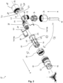
- Figure 2 shows an exploded view of the Figure 1 shown connector 10.
- the first connector section 14 has a first housing part 20, a second housing part 22, an insulating body 24 and a connecting means 26.
- the connection housing part 18 has a first connection section 28 and a second connection section 30.
- the first connector section 14 can be connected in a force-fitting manner to the connecting housing part 18 and in particular to the first connecting section 28.
- the second connector section 16 has a third housing part 32, a cable securing element 34 and a fourth housing part 36.
- the third housing part 32 and the second connecting section 30 are designed to be connected to one another in a form-fitting manner. Furthermore, the assembled connector 10, having the first connector section 14, the second connector section 16 and the connecting housing part 18, forms a housing in which the cable 12 is guided.
- the insulating body 24 has a connector-side electrical contacting means 54, for example one or more pins and/or sockets, which electrically connect the cable 12 to a complementary connector-receiving-side electrical contacting means (not shown).
- the complementary connector receptacle can be made of a dielectric material so that the connector-side electrical contacting means 54 is electrically insulated from other elements of the connector 10, in particular from other connector-side electrical contacting means 54 that are arranged on the insulating body 24.
- first housing part 20, the second housing part 22, the third housing part 32, the fourth housing part 36 and the cable securing element 34 are designed as essentially elongated hollow bodies, preferably as an essentially hollow cylindrical body.
- the longitudinal axis of the first housing part 20, the second housing part 22 coincide with the longitudinal axis L1 of the first connector section 14.
- the longitudinal axis of the third housing part 32, the cable securing element 34 and the fourth housing part 36 coincide with the longitudinal axis L2 of the second connector section 16.
- the insulating body 24 can have a substantially cylindrical shape, wherein the cylinder axis of the insulating body 24 coincides with the longitudinal axis L1 of the first connector section 14 in the assembled state of the connector 10.
- Figure 3 shows a sectional view of the connector 10 along the Figure 1 AA line shown.
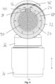
- Figure 4 shows a cross-sectional view of the connector 10 along the Figure 1 shown BB line.
- Figure 5 shows a cross-sectional view of the connector 10 along the Figure 1 shown CC line.
- the insulating body 24 is at least partially along the Insertion direction E in the first housing part 20.
- the insulating body 24 is arranged in a form-fitting manner in the circumferential direction Ur of the first housing part 20 in the first housing part 20.
- the insulating body 24 cannot be moved relative to the first housing part 20 in the circumferential direction Ur of the first housing part 20.
- the circumferential direction Ur lies in a fictitious plane which is essentially perpendicular to the insertion direction E.
- the first housing part 14 is arranged at least in sections along the insertion direction E within the second housing part 22.
- the first housing part 20 is arranged in a form-fitting manner in the circumferential direction Ur of the first housing part 20 in the second housing part 22.
- the first housing part 20 cannot be moved relative to the second housing part 22 in the circumferential direction Ur of the first housing part 20.
- the second housing part 22 has a circumferential direction Ur which runs essentially parallel to the circumferential direction Ur of the first housing part 20.
- the insulating body 24 has an anti-twist element 38 on its outer surface (see Figures 2 , 3 and 4 ). Furthermore, the first housing part 20 has a first housing part-side anti-twist element 40 which is designed to be complementary to the insulation body-side anti-twist element 38 and which is arranged on an inner side of the first housing part 20 which faces the insulation body 24. As can be seen from the Figures 2 and 4 As can be seen, the anti-twisting element 38 on the insulation body side is designed as a projection, and the first anti-twisting element 40 on the housing part side is designed as a recess that extends from the inside to the outside through the wall of the first housing part 20.
- the anti-twisting element 38 on the insulation body side and the first anti-twisting element 40 on the housing part side engage with one another in order to arrange the insulation body 24 in a form-fitting manner in the first housing part 20.
- the second housing part 22 has a second housing-part-side anti-twist element 42, which is designed to be complementary to the first housing-part-side anti-twist element 40.
- the second housing-part-side anti-twist element 42 and the first housing-part-side anti-twist element 40 are designed to engage with one another.
- the second housing-part-side anti-twist element 42 can be formed on an inner side of the second housing part 22, which faces the first housing part 20.
- the second housing-part-side anti-twist element 42 is preferably designed as a projection, which can engage with the first housing-part-side anti-twist element 40.
- the first housing-part-side anti-twisting element 40 can be used for the positive-locking arrangement of the insulating body 24 in the first housing part 20 and for the positive-locking arrangement of the first housing part 20 in the second housing part 22.
- the first housing part-side anti-twist element 40 specifies an orientation about the longitudinal axis of the first housing part-side anti-twist element 40, in which the insulating body 24 can be inserted into the first housing part 20.
- the second housing part 22 is movable along the insertion direction E relative to the first housing part 20, wherein the movement path or distance along the insertion direction E is limited.
- the first housing part 20 further comprises a resiliently mounted securing element 44 which is designed to engage positively in the connector receptacle. The positive engagement of the securing element 44 in the connector receptacle secures the connector 10 to the connector receptacle. Furthermore, moving the second housing part 22 against the insertion direction E and relative to the first housing part 20 results in the engagement of the securing element 44 in the connector receptacle being released or cancelled, so that the connector 10 can be removed from the connector receptacle.
- the second housing part 22 is arranged on the outside of the connector 10 so that it can be operated by a user.
- the second housing part 22 is moved relative to the first housing part 20 in the direction of insertion direction E, whereby the securing element 44 is released in order to engage positively in the connector receptacle.
- the second housing part 44 has a through-opening 46 through which the securing element 44 extends outwards.
- the through-opening 46 is formed in the insertion section 15 of the first connector section 14.
- the securing element 44 forms a stop against which the second housing part 22 with the through-opening 46 strikes when the second housing part 22 is moved relative to the first housing part 20 in the direction of the insertion direction E.
- the securing element 44 and the through-opening 46 limit the movement path of the second housing part 22 in the direction of the insertion direction E relative to the first housing part 20.
- the first housing part 20 has a spring element 48, which is arranged or formed in the housing wall or in the wall of the first housing part 20.
- the spring element 48 is in particular formed integrally with the first housing part 20 and is formed by a recess 50 which runs around the spring element 48 at least in sections and which is provided in the housing wall.
- the longitudinal direction of the spring element 48 can extend essentially parallel to the insertion direction E, wherein an end of the spring element 48 lying in the insertion direction E is not connected to the first housing part 20 and an end of the spring element 48 lying opposite to the insertion direction E is connected to the first housing part 20.
- the end of the spring element 48 lying in the insertion direction E can have the securing element 44 on its outer side, which faces the second housing part 22, for example in the form of a nose or a projection.
- first housing part 20 can also have more than one securing element 44 with corresponding spring elements 48, and that the second housing part 22 can accordingly have several passage openings 46
- first housing part 20 has three securing elements 44, which are evenly distributed in the circumferential direction Ur on the first housing part 20. Accordingly, the second housing part 22 has three through openings 46.
- the second housing part 22 has an orientation aid 52 in the form of a projection on the outside in the area of the insertion section 15, with which the plug connector 10 can be inserted into the plug connector receptacle in a predetermined orientation. Furthermore, the second housing part 22 can be connected to the complementary plug connector receptacle in a form-fitting manner in the circumferential direction Ur of the second housing part 22, preferably by means of the orientation aid 52.
- this can ensure that a connector-side electrical contacting means 54 arranged on the insulating body 24 can be correctly electrically connected, in particular contacted, with a complementary connector receptacle-side electrical contacting means (not shown) or that several connector-side electrical contacting means 54 of the insulating body 24 are correctly assigned to respective complementary connector receptacle-side electrical contacting means. Furthermore, a torque acting on the elements of the first connector section 14, in particular on the first housing part 20, on the second housing part 22 and/or on the insulating body 24, can be transmitted or diverted to the connector receptacle.
- the electrical contacting means 54 on the connector side are designed to electrically connect wires or strands of the cable 12 to the corresponding electrical contacting means on the connector receptacle side.
- the electrical contacting means 54 on the connector side can be designed in particular as pins and/or sockets.
- the insulating body 24 is made of a dielectric material in order to electrically insulate the electrical contacting means 54 on the connector side from other elements of the connector 10.
- the electrical contacting means 54 on the connector side are each arranged in or on the insulating body 24 so as to be electrically insulated from one another.
- the connecting means 26 is shown as being arranged so as to be rotatable at least in sections along the insertion direction E between the first housing part 20 and the second housing part 22.
- the connecting means 26 can preferably be designed as a hollow body, preferably as a hollow cylindrical body, for example as a nut, which can be non-positively connected to the first connecting section 28, which is preferably designed as a thread.
- the axis of rotation of the connecting means 26 can coincide with the longitudinal axis L1 of the first connector section 14.
- the connecting means 26 can be arranged between the first housing part 20 and the second housing part 22 in such a way that the connecting means 26 cannot be detached from the first connector section 14 contrary to the insertion direction E.
- the connecting means 26 can have a stop 56 running around in the circumferential direction Ur on the inner side facing the first housing part 22, which stop 56, when the connecting means 26 moves relative to the first housing part 20 against the insertion direction E, strikes a stop 58 running around in the circumferential direction Ur on the outer side of the first housing part 20 facing the connecting means 26.
- the first housing part 20 is inserted into the connecting means 26 in the direction of the insertion direction E.
- the second housing part 22 can be pushed onto the first housing part 20 against the insertion direction E, so that the securing element 44 protrudes through the passage opening 46.
- the mobility of the second housing part 22 relative to the first housing part 20 against the insertion direction E can be limited at least by the connecting means 26.
- the engagement of the second housing-part-side anti-twist element 42 with the first housing-part-side anti-twist element 40 can limit the mobility of the second housing part 22 relative to the first housing part 20 against the insertion direction E.
- the first housing part 20 can have a shoulder 60 running around the circumference in the circumferential direction Ur, at which the outer diameter of the first housing part 20 decreases abruptly in the direction of the insertion direction E.
- the shoulder 60 can limit the mobility of the second housing part 22 relative to the first housing part 20 against the Limit the insertion direction E by the second housing part 22 striking the shoulder 60 when the second housing part 22 moves relative to the first housing part 20 against the insertion direction E.
- the structure of the second connector section 16 is described below with .
- the cable securing element 34 can be arranged in the cable routing direction K between the third housing part 32 and the fourth housing part 36. Furthermore, the cable securing element 34 can be designed as a clamping bush which at least partially surrounds the cable 12 along the cable routing direction K.
- the cable securing element 34 can be arranged between the third housing part 32 and the fourth housing part 36 in such a way that by force-fittingly connecting the third housing part 32 to the fourth housing part 36, the cable securing element 34 is deformed in order to secure the position of the cable 12 in the second connector section 16.
- the fourth housing part 36 can be designed as a nut which can be screwed to the third housing part 32.
- the third housing part 32 can be positively connected to the second connecting section 30 of the connecting housing part 18.
- the connecting housing part 18 and the third housing part 32 are designed such that the connecting housing part 18 can be pushed onto the third housing part 32 in the direction of the insertion direction E in order to positively connect the third housing part 32 to the connecting housing part 18 in the direction of the cable guide direction K.
- the third housing part 32 has guide elements 62 on the connector section side at an end lying in the cable guide direction K, which can come into positive engagement with complementary guide elements 64 on the connecting housing part side of the second connecting section 30 of the connecting housing part 18.
- the connector section-side guide elements 62 may consist of two guide elements which are arranged in relation to the longitudinal axis L2 of the second connector section 16 are arranged opposite each other and whose longitudinal direction runs substantially parallel to the insertion direction E.
- connection housing part 18 is essentially hollow-cylindrical in the direction of the insertion direction E and is delimited by an end wall 66 at an end opposite to the insertion direction E. Furthermore, the outer surface of the connection housing part 18 is not completely closed and has a recess 68 which, when the plug connector 10 is connected, enables the cable 12 to be fed to the insulation body 24. Furthermore, the guide elements 64 on the connection housing part side are formed on the recess 68, the longitudinal direction of which runs essentially parallel to the insertion direction E.
- connection housing part 18 To connect the connection housing part 18 to the third housing part 32, the connection housing part 18 is pushed onto the third housing part 32 in the insertion direction E in such a way that the guide elements 64 on the connection housing part side are moved relative to the guide elements 62 on the connector section side in the insertion direction E. Furthermore, the connecting housing part 18 abuts against the third housing part 32, so that the mobility of the connecting housing part 18 relative to the third housing part 32 in the insertion direction E is limited. Furthermore, the recess 68 can continue into the first connecting section 28, so that the external thread of the connecting section 28 is not continuous or continuous around the circumference.
- connection housing part 18 has a connection housing part-side alignment element 70, which extends from the first connection section 28 in the direction of the insertion direction E.
- first housing part 20 has a housing part-side alignment element 72, which is complementary to the connection housing part-side alignment element 70 and which, when the connector 10 is assembled, engages with the connection housing part-side alignment element 70 in order to determine an orientation of the first housing part 20 relative to the connection housing part 18 around the longitudinal axis L1.
- the connection housing part-side alignment element 70 can consist of at least one projection, wherein in the in Figure 2 In the embodiment shown, three projections are shown, and the housing part-side alignment element 72 consists of corresponding recesses which engage in the connection housing part-side alignment element 70. In other words, the connection housing part-side alignment element 70 and the housing part-side alignment element 72 are interlocked with one another in the assembled state of the connector 10.
- the connector 10 has a spacer element 74 (see Figures 2 and 3 ), which spaces the insulating body 24 from the connecting housing part 18 in the direction of the insertion direction E.
- the spacer element 74 can in particular enclose the insulating body 24 in sections along the insertion direction E.
- a section of the insulating body 24 along the insertion direction E is not encompassed by the spacer element 74.
- the anti-twist element 38 on the insulating body side is not covered by the spacer element 74.
- the spacer element 74 can be arranged at least in sections in the connecting housing part 18 and in particular in the first connecting section 28.
- the spacer element 74 can preferably be formed by two symmetrical, preferably mirror-symmetrical, half-shell elements 74a/74b which, when assembled, form an elongated hollow body, preferably a substantially hollow cylindrical body, the longitudinal axis of which runs substantially parallel to the insertion direction E and coincides with the longitudinal axis of the insulating body 24.
- the insulation body 24 is arranged at an end of the spacer element 74 lying in the insertion direction E in such a way that its position is fixed relative to the spacer element 74 that the position of the insulation body 24 relative to the spacer element 74 is fixed along the insertion direction E.
- the insulation body 24 can have an insulation body-side positioning element 76 which can engage with a complementary spacer element-side positioning element 78 of the spacer element 74 so that the insulation body 24 and the spacer element 74 are arranged in a form-fitting manner along the insertion direction E.
- the insulation body side Positioning element 76 is designed as a projection on the outside of the insulating body 24, which faces the spacer element 74, and runs in the circumferential direction Ur of the insulating body 24.
- the positioning element 78 on the spacer element side is designed as a groove on the inside of the spacer element 74, which faces the insulating body 24, running in the circumferential direction Ur.
- the spacer element 74 is arranged in the assembled state of the plug connector 10 at least in sections along the insertion direction E in the first housing part 20.
- a method for assembling the plug connector 10 is shown.
- a cable 12 is guided through the fourth housing part 36, through the cable securing element 34 and through the third housing part 32 in the cable routing direction K.
- a shield for the cable 12 is arranged between the cable securing element 34 and the third housing part 36.
- wires or strands of the cable 12 are connected to corresponding electrical contacting means 54 of the insulating body 24 on the connector side, for example by soldering.
- the spacer element 74 is then arranged on the insulating body 24 and the spacer element 74 with the insulating body 24 is arranged at an end of the third housing part 32 lying in the cable direction K.
- the connecting housing part 18 is positively connected to the third housing part 32 by means of the second connecting section 30, wherein the spacer element 74 is arranged in sections along the insertion direction E in the connecting housing part 18.
- first housing part 20 is inserted into the connecting means 26 in the insertion direction E.
- the second housing part 22 is then pushed onto the first housing part 20 against the insertion direction E, so that the securing element 44 passes through the through-opening 46.
- the first housing part 20 is then pushed onto the insulating body 24 against the insertion direction E and the connecting means 26 is connected in a force-fitting manner to the first connecting section 28.
- the first housing part 20 is secured by means of the housing part-side alignment element 72 and the connection housing part-side alignment element 70 with respect to the connection housing part 18.
- the fourth housing part 36 can be force-fitted to the third housing part 32, so that the cable securing element 34 is deformed in order to determine the position of the cable 12 in the second connector section 16 or to secure the cable 12 in the connector 17.
Landscapes
- Engineering & Computer Science (AREA)
- Manufacturing & Machinery (AREA)
- Details Of Connecting Devices For Male And Female Coupling (AREA)
- Connector Housings Or Holding Contact Members (AREA)
Claims (13)
- Connecteur enfichable coudé (10), notamment connecteur enfichable coudé push-pull, présentant :- une première section de connecteur enfichable (14) pour enficher le connecteur enfichable (10) en direction d'une direction d'enfichage (E) dans un logement de connecteur enfichable complémentaire, la première section de connecteur enfichable (14) présentant un corps isolant (24) qui présente un moyen de contact électrique côté connecteur enfichable (54) pour la connexion électrique d'un câble (12) avec un moyen de contact électrique complémentaire côté logement de connecteur enfichable ;- une deuxième section de connecteur enfichable (16) pour insérer le câble (12) dans le connecteur enfichable (10), le câble (12) pouvant être agencé dans la deuxième section de connecteur enfichable (16) le long d'une direction de guidage de câble (K) ; et- une partie de boîtier de connexion (18) pour connecter la première section de connecteur enfichable (14) et la deuxième section de connecteur enfichable (16) de telle sorte que la direction de guidage de câble (K) soit différente de la direction d'enfichage (E),la partie de boîtier de connexion (18) présentant une première section de connexion (28) qui peut être connectée par force à la première section de connecteur enfichable (14),caractérisé en ce quela partie de boîtier de connexion (18) présente une deuxième section de connexion (30) qui peut être connectée par complémentarité de forme à la deuxième section de connecteur enfichable (16) le long de la direction de guidage de câble (K),pour assembler le connecteur enfichable (10), la deuxième section de connecteur enfichable (16) devant d'abord être connectée à la deuxième section de connexion (30) de la partie de boîtier de connexion (18) et la première section de connecteur enfichable (14) devant ensuite être connectée à la première section de connexion (28) de la partie de boîtier de connexion (18), etla connexion par force de la première section de connecteur enfichable (14) à la partie de boîtier de connexion (18) empêchant un détachement de la deuxième section de connecteur enfichable (16) de la partie de boîtier de connexion (18).
- Connecteur enfichable coudé (10) selon la revendication 1, la première section de connecteur enfichable (14) présentant une première partie de boîtier (20) et une deuxième partie de boîtier (22), la première partie de boîtier (20) entourant le corps isolant (24) au moins par sections le long de la direction d'enfichage (E) et la deuxième partie de boîtier (22) entourant la première partie de boîtier (20) au moins par sections le long de la direction d'enfichage (E), et
le connecteur enfichable (10) présentant de préférence un moyen de connexion (26) agencé au moins par sections entre la première partie de boîtier (20) et la deuxième partie de boîtier (22) et monté de manière rotative, lequel peut être connecté par force à la première section de connexion (28). - Connecteur enfichable coudé (10) selon la revendication 2, la partie de boîtier de connexion (18) présentant un élément d'orientation (70) côté partie de boîtier de connexion, qui s'étend dans la direction d'enfichage (E) à partir de la première section de connexion (28) et qui est conçu pour venir en prise avec un élément d'orientation (72) complémentaire, côté partie de boîtier, de la première partie de boîtier (20), afin d'orienter la position de la première section de connecteur enfichable (14) par rapport à la partie de boîtier de connexion (18), et/oule corps isolant (24) étant agencé par complémentarité de forme dans la première partie de boîtier (20) dans la direction périphérique (Ur) de la première partie de boîtier (20) ; et/oula première partie de boîtier (20) étant agencée par complémentarité de forme dans la deuxième partie de boîtier (22) dans la direction périphérique (Ur) de la deuxième partie de boîtier (22).
- Connecteur enfichable coudé (10) selon la revendication 2 ou 3, le corps isolant (24) présentant un élément de protection contre la torsion (38) côté corps isolant, notamment une saillie ou un évidement, et la première partie de boîtier (20) présentant un premier élément de protection contre la torsion (40) côté partie de boîtier, notamment un évidement ou une saillie, l'élément de protection contre la torsion (38) côté corps isolant et le premier élément de protection contre la torsion (40) côté partie de boîtier s'engageant l'un dans l'autre de telle sorte que le corps isolant (24) est agencé par complémentarité de forme dans la première partie de boîtier (20) dans la direction périphérique (Ur) de la première partie de boîtier (20).
- Connecteur enfichable coudé (10) selon la revendication 4, la deuxième partie de boîtier (22) présentant un deuxième élément de protection contre la torsion (42) côté partie de boîtier, notamment une saillie ou un évidement, et le deuxième élément de protection contre la torsion (42) côté partie de boîtier et le premier élément de protection contre la torsion (40) côté partie de boîtier s'engageant l'un dans l'autre de telle sorte que la première partie de boîtier (20) est agencée par complémentarité de forme dans la deuxième partie de boîtier (22) dans la direction périphérique (Ur) de la deuxième partie de boîtier (22).
- Connecteur enfichable coudé (10) selon l'une quelconque des revendications 2 à 5, la deuxième partie de boîtier (22) étant mobile par rapport à la première partie de boîtier (20) le long de la direction d'enfichage (E).
- Connecteur enfichable coudé (10) selon l'une quelconque des revendications 2 à 6, la première partie de boîtier (20) présentant un élément de sécurité (44) monté avec possibilité de rappel, qui est conçu pour s'engager par complémentarité de forme dans le logement de connecteur enfichable, et, de préférence, un déplacement de la deuxième partie de boîtier (22) par rapport à la première partie de boîtier (20) le long de la direction d'enfichage (E), notamment à l'encontre de la direction d'enfichage (E), déclenchant un engagement de l'élément de sécurité (44) dans le logement de connecteur enfichable.
- Connecteur enfichable coudé (10) selon l'une quelconque des revendications 1 à 7, la deuxième section de connexion (30) de la partie de boîtier de connexion (18) présentant deux éléments de guidage opposés (64) côté partie de boîtier de connexion, et la deuxième section de connecteur enfichable (16) présentant des éléments de guidage (62) côté section de connecteur enfichable, complémentaires respectivement des éléments de guidage (64) côté partie de boîtier de connexion, et
pour connecter la partie de boîtier de connexion (18) à la deuxième section de connecteur enfichable (16), les éléments de guidage (64) côté partie de boîtier de connexion et les éléments de guidage (62) côté section de connecteur enfichable s'engageant les uns dans les autres et étant mobiles les uns par rapport aux autres le long de la direction d'enfichage (E). - Connecteur enfichable coudé (10) selon l'une quelconque des revendications précédentes, la deuxième section de connecteur enfichable (16) présentant en outre :- un élément de sécurité de câble (34) qui entoure le câble (12) au moins par sections le long de la direction de guidage de câble,- une troisième partie de boîtier (32), et- une quatrième partie de boîtier (36), qui peut être connectée par force à la troisième partie de boîtier (32), l'élément de sécurité de câble (34) étant agencé au moins par sections dans la troisième partie de boîtier (32) et/ou la quatrième partie de boîtier (36),en option, l'élément de sécurité de câble (34), la troisième partie de boîtier (32) et/ou la quatrième partie de boîtier (36) étant configurés sous forme de corps creux essentiellement allongés et leur axe longitudinal étant essentiellement parallèle à la direction de guidage de câble (K).
- Connecteur enfichable coudé (10) selon la revendication 9, l'élément de sécurité de câble (34) étant configuré pour être déformable et, en connectant par force la quatrième partie de boîtier (36) à la troisième partie de boîtier (32), l'élément de sécurité de câble (34) étant déformé de telle sorte que le câble (12) est sécurisé dans la deuxième section de connecteur enfichable (15), et/ou
la troisième partie de boîtier (32) présentant les éléments de guidage (72) côté section de connecteur enfichable. - Connecteur enfichable coudé (10) selon l'une quelconque des revendications précédentes, la première partie de boîtier (20) et la deuxième partie de boîtier (22) étant configurées sous forme de corps creux essentiellement allongés et leur axe longitudinal étant essentiellement parallèle à la direction d'enfichage (E), et/oula direction d'enfichage (E) et la direction de guidage de câble (K) formant essentiellement un angle de 90° l'une par rapport à l'autre, et/ouprésentant en outre un élément d'écartement (74) qui éloigne le corps isolant (24) de la partie de boîtier de connexion (18) en direction de la direction d'enfichage (E).
- Procédé d'assemblage d'un connecteur enfichable coudé (10), notamment d'un connecteur enfichable coudé push-pull, le procédé présentant les étapes suivantes :(a) la fourniture d'une première section de connecteur enfichable (14) du connecteur enfichable, la première section de connecteur enfichable (14) étant configurée pour enficher le connecteur enfichable (10) dans un logement de connecteur enfichable complémentaire en direction d'une direction d'enfichage (E) ;(b) l'insertion d'une extrémité de câble d'un câble (12) en direction d'une direction de guidage de câble (K) dans une deuxième section de connecteur enfichable (16) du connecteur enfichable (10) et le passage de l'extrémité de câble à travers la deuxième section de connecteur enfichable (16), le câble (12) étant agencé dans la deuxième section de connecteur enfichable (16) le long de la direction de guidage de câble (K) ;(c) la connexion de l'extrémité de câble à un corps isolant (24) ;(d) le coudage du corps isolant (24) par rapport à la deuxième section de connecteur enfichable (16) ;(e) la connexion d'une partie de boîtier de connexion (18) du connecteur enfichable à la deuxième section de connecteur enfichable (16) de telle sorte qu'une deuxième section de connexion (30) de la partie de boîtier de connexion (18) soit connectée par complémentarité de forme à la deuxième section de connecteur enfichable (16) le long de la direction de guidage de câble (K) ;(f) l'insertion du corps isolant (24) dans la première section de connecteur enfichable (14) ; et(g) la connexion de la première section de connecteur enfichable (14) à la partie de boîtier de connexion (18) de telle sorte que la direction de guidage de câble (K) soit différente de la direction d'enfichage (E) et qu'une première section de connexion (28) de la partie de boîtier de connexion (18) soit connectée par force à la première section de connecteur enfichable (14), la connexion par force de la première section de connecteur enfichable (14) à la partie de boîtier de connexion (18) empêchant un détachement de deuxième section de connecteur enfichable (16) de la partie de boîtier de connexion (18).
- Procédé selon la revendication 12, il étant prévu l'étape suivante entre les étapes (f) et (g) :
l'orientation de la première section de connexion (14) par rapport à la partie de boîtier de connexion (18) au moyen d'un élément d'orientation (70) côté partie de boîtier de connexion prévu sur la partie de boîtier de connexion et d'un élément d'orientation (72) complémentaire côté partie de boîtier prévu sur la première section de connecteur enfichable (14).
Applications Claiming Priority (1)
| Application Number | Priority Date | Filing Date | Title |
|---|---|---|---|
| DE102020214935.6A DE102020214935B4 (de) | 2020-11-27 | 2020-11-27 | Gewinkelter Steckverbinder und Verfahren zum Zusammensetzen eines gewinkelten Steckverbinders |
Publications (3)
| Publication Number | Publication Date |
|---|---|
| EP4007082A1 EP4007082A1 (fr) | 2022-06-01 |
| EP4007082C0 EP4007082C0 (fr) | 2024-11-20 |
| EP4007082B1 true EP4007082B1 (fr) | 2024-11-20 |
Family
ID=78806309
Family Applications (1)
| Application Number | Title | Priority Date | Filing Date |
|---|---|---|---|
| EP21210680.1A Active EP4007082B1 (fr) | 2020-11-27 | 2021-11-26 | Connecteur enfichable coudé et procédé d'assemblage d'un connecteur enfichable coudé |
Country Status (2)
| Country | Link |
|---|---|
| EP (1) | EP4007082B1 (fr) |
| DE (1) | DE102020214935B4 (fr) |
Families Citing this family (2)
| Publication number | Priority date | Publication date | Assignee | Title |
|---|---|---|---|---|
| DE102023128623A1 (de) * | 2023-10-18 | 2025-04-24 | Yamaichi Electronics Deutschland Gmbh | Gewinkelter steckverbinder und verfahren zum assemblieren eines gewinkelten steckverbinders |
| DE102024122060A1 (de) * | 2024-08-02 | 2026-02-05 | Lufthansa Technik Aktiengesellschaft | Steckergehäuse |
Family Cites Families (4)
| Publication number | Priority date | Publication date | Assignee | Title |
|---|---|---|---|---|
| CH616279A5 (fr) | 1977-07-06 | 1980-03-14 | Interlemo Holding Sa | |
| JP5566095B2 (ja) * | 2009-03-31 | 2014-08-06 | マスプロ電工株式会社 | 同軸ケーブルコネクタ |
| HUE043283T2 (hu) | 2016-08-30 | 2019-08-28 | Interlemo Holding Sa | Könyök csatlakozó |
| DE102017104982B3 (de) * | 2017-03-09 | 2018-08-02 | Te Connectivity Industrial Gmbh | Elektrischer Stecker mit spezifischer Erdung von Außenteilen |
-
2020
- 2020-11-27 DE DE102020214935.6A patent/DE102020214935B4/de active Active
-
2021
- 2021-11-26 EP EP21210680.1A patent/EP4007082B1/fr active Active
Also Published As
| Publication number | Publication date |
|---|---|
| DE102020214935B4 (de) | 2023-07-27 |
| EP4007082C0 (fr) | 2024-11-20 |
| EP4007082A1 (fr) | 2022-06-01 |
| DE102020214935A1 (de) | 2022-06-02 |
Similar Documents
| Publication | Publication Date | Title |
|---|---|---|
| EP2434582B1 (fr) | Borne de connexion | |
| EP3394936B1 (fr) | Connecteur enfichable | |
| EP2797175B1 (fr) | Fiche pour un câble de données et/ou de télécommunications multi-brins | |
| EP3735722B1 (fr) | Support de contact et connecteur pour un agencement de contacts hybride blindé | |
| EP3767750B1 (fr) | Connecteur enfichable électrique, élément de protection isolant et procédé de montage d'un connecteur enfichable électrique | |
| DE69305320T2 (de) | Modularer koaxialer Kabelverbinder | |
| EP4007082B1 (fr) | Connecteur enfichable coudé et procédé d'assemblage d'un connecteur enfichable coudé | |
| EP3869632A1 (fr) | Prise de recharge pour un véhicule électrique | |
| DE102018118405B3 (de) | Steckverbinder sowie Steckverbindung mit einem solchen Steckverbinder | |
| EP0968548A1 (fr) | Douille munie de zones de contact a configuration hyperboloidale | |
| DE102014116482B4 (de) | Kontaktelement | |
| EP3364507A1 (fr) | Connecteur électrique pour un câble électrique multi-fils | |
| DE102024125089A1 (de) | Steckereinsatz | |
| EP4443665A1 (fr) | Connecteur coaxial multi-parties configurable de façon variable par rapport à la géométrie d'interface | |
| DE102020214934B4 (de) | Gewinkelter Steckverbinder und Verfahren zum Zusammensetzen eines gewinkelten Steckverbinders | |
| EP4254683B1 (fr) | Connecteur enfichable rond et procédé de fabrication d'un connecteur enfichable rond | |
| EP4246738B1 (fr) | Connecteur enfichable rond, utilisation d'un connecteur enfichable rond et procédé de fabrication d'un connecteur enfichable rond | |
| DE102021100858B4 (de) | Crimpverbinder zum Anschluss eines einen Kabelschirm aufweisenden Kabels an eine elektronische Baugruppe | |
| EP3896793A1 (fr) | Connecteur pour câble de données | |
| EP4636960A1 (fr) | Connecteur de carte de circuit imprimé, ensemble carte de circuit imprimé et procédé d'assemblage d'un connecteur de carte de circuit imprimé | |
| EP4622017A1 (fr) | Ensemble de terminaison d'un ensemble connecteur de câble, ensemble connecteur de câble et procédé d'assemblage d'un ensemble connecteur de câble | |
| WO2026032475A1 (fr) | Insert de fiche | |
| DE102020127124A1 (de) | Elektrisch leitende Verbindungsanordnung | |
| WO2006034839A1 (fr) | Fiche ou element de couplage comportant un element conducteur interne produit au moyen d'un procede de pliage par estampage |
Legal Events
| Date | Code | Title | Description |
|---|---|---|---|
| PUAI | Public reference made under article 153(3) epc to a published international application that has entered the european phase |
Free format text: ORIGINAL CODE: 0009012 |
|
| STAA | Information on the status of an ep patent application or granted ep patent |
Free format text: STATUS: THE APPLICATION HAS BEEN PUBLISHED |
|
| AK | Designated contracting states |
Kind code of ref document: A1 Designated state(s): AL AT BE BG CH CY CZ DE DK EE ES FI FR GB GR HR HU IE IS IT LI LT LU LV MC MK MT NL NO PL PT RO RS SE SI SK SM TR |
|
| STAA | Information on the status of an ep patent application or granted ep patent |
Free format text: STATUS: REQUEST FOR EXAMINATION WAS MADE |
|
| 17P | Request for examination filed |
Effective date: 20221125 |
|
| RBV | Designated contracting states (corrected) |
Designated state(s): AL AT BE BG CH CY CZ DE DK EE ES FI FR GB GR HR HU IE IS IT LI LT LU LV MC MK MT NL NO PL PT RO RS SE SI SK SM TR |
|
| GRAP | Despatch of communication of intention to grant a patent |
Free format text: ORIGINAL CODE: EPIDOSNIGR1 |
|
| STAA | Information on the status of an ep patent application or granted ep patent |
Free format text: STATUS: GRANT OF PATENT IS INTENDED |
|
| RIC1 | Information provided on ipc code assigned before grant |
Ipc: H01R 13/504 20060101ALI20240119BHEP Ipc: H01R 13/502 20060101ALI20240119BHEP Ipc: H01R 13/56 20060101ALI20240119BHEP Ipc: H01R 13/58 20060101ALI20240119BHEP Ipc: H01R 13/629 20060101ALI20240119BHEP Ipc: H01R 24/86 20110101ALI20240119BHEP Ipc: H01R 43/20 20060101ALI20240119BHEP Ipc: H01R 24/54 20110101AFI20240119BHEP |
|
| INTG | Intention to grant announced |
Effective date: 20240207 |
|
| GRAJ | Information related to disapproval of communication of intention to grant by the applicant or resumption of examination proceedings by the epo deleted |
Free format text: ORIGINAL CODE: EPIDOSDIGR1 |
|
| STAA | Information on the status of an ep patent application or granted ep patent |
Free format text: STATUS: REQUEST FOR EXAMINATION WAS MADE |
|
| GRAP | Despatch of communication of intention to grant a patent |
Free format text: ORIGINAL CODE: EPIDOSNIGR1 |
|
| STAA | Information on the status of an ep patent application or granted ep patent |
Free format text: STATUS: GRANT OF PATENT IS INTENDED |
|
| INTC | Intention to grant announced (deleted) | ||
| INTG | Intention to grant announced |
Effective date: 20240617 |
|
| GRAS | Grant fee paid |
Free format text: ORIGINAL CODE: EPIDOSNIGR3 |
|
| GRAA | (expected) grant |
Free format text: ORIGINAL CODE: 0009210 |
|
| STAA | Information on the status of an ep patent application or granted ep patent |
Free format text: STATUS: THE PATENT HAS BEEN GRANTED |
|
| AK | Designated contracting states |
Kind code of ref document: B1 Designated state(s): AL AT BE BG CH CY CZ DE DK EE ES FI FR GB GR HR HU IE IS IT LI LT LU LV MC MK MT NL NO PL PT RO RS SE SI SK SM TR |
|
| REG | Reference to a national code |
Ref country code: GB Ref legal event code: FG4D Free format text: NOT ENGLISH |
|
| REG | Reference to a national code |
Ref country code: DE Ref legal event code: R081 Ref document number: 502021005856 Country of ref document: DE Owner name: YAMAICHI ELECTRONICS DEUTSCHLAND GMBH, DE Free format text: FORMER OWNER: ANMELDERANGABEN UNKLAR / UNVOLLSTAENDIG, 80297 MUENCHEN, DE |
|
| REG | Reference to a national code |
Ref country code: CH Ref legal event code: EP |
|
| REG | Reference to a national code |
Ref country code: DE Ref legal event code: R096 Ref document number: 502021005856 Country of ref document: DE |
|
| REG | Reference to a national code |
Ref country code: IE Ref legal event code: FG4D Free format text: LANGUAGE OF EP DOCUMENT: GERMAN |
|
| U01 | Request for unitary effect filed |
Effective date: 20241126 |
|
| U07 | Unitary effect registered |
Designated state(s): AT BE BG DE DK EE FI FR IT LT LU LV MT NL PT RO SE SI Effective date: 20241202 |
|
| U20 | Renewal fee for the european patent with unitary effect paid |
Year of fee payment: 4 Effective date: 20241220 |
|
| PG25 | Lapsed in a contracting state [announced via postgrant information from national office to epo] |
Ref country code: HR Free format text: LAPSE BECAUSE OF FAILURE TO SUBMIT A TRANSLATION OF THE DESCRIPTION OR TO PAY THE FEE WITHIN THE PRESCRIBED TIME-LIMIT Effective date: 20241120 Ref country code: IS Free format text: LAPSE BECAUSE OF FAILURE TO SUBMIT A TRANSLATION OF THE DESCRIPTION OR TO PAY THE FEE WITHIN THE PRESCRIBED TIME-LIMIT Effective date: 20250320 |
|
| PG25 | Lapsed in a contracting state [announced via postgrant information from national office to epo] |
Ref country code: ES Free format text: LAPSE BECAUSE OF FAILURE TO SUBMIT A TRANSLATION OF THE DESCRIPTION OR TO PAY THE FEE WITHIN THE PRESCRIBED TIME-LIMIT Effective date: 20241120 |
|
| PG25 | Lapsed in a contracting state [announced via postgrant information from national office to epo] |
Ref country code: NO Free format text: LAPSE BECAUSE OF FAILURE TO SUBMIT A TRANSLATION OF THE DESCRIPTION OR TO PAY THE FEE WITHIN THE PRESCRIBED TIME-LIMIT Effective date: 20250220 |
|
| PG25 | Lapsed in a contracting state [announced via postgrant information from national office to epo] |
Ref country code: GR Free format text: LAPSE BECAUSE OF FAILURE TO SUBMIT A TRANSLATION OF THE DESCRIPTION OR TO PAY THE FEE WITHIN THE PRESCRIBED TIME-LIMIT Effective date: 20250221 |
|
| PG25 | Lapsed in a contracting state [announced via postgrant information from national office to epo] |
Ref country code: PL Free format text: LAPSE BECAUSE OF FAILURE TO SUBMIT A TRANSLATION OF THE DESCRIPTION OR TO PAY THE FEE WITHIN THE PRESCRIBED TIME-LIMIT Effective date: 20241120 |
|
| PG25 | Lapsed in a contracting state [announced via postgrant information from national office to epo] |
Ref country code: RS Free format text: LAPSE BECAUSE OF FAILURE TO SUBMIT A TRANSLATION OF THE DESCRIPTION OR TO PAY THE FEE WITHIN THE PRESCRIBED TIME-LIMIT Effective date: 20250220 |
|
| REG | Reference to a national code |
Ref country code: CH Ref legal event code: PL |
|
| PG25 | Lapsed in a contracting state [announced via postgrant information from national office to epo] |
Ref country code: SM Free format text: LAPSE BECAUSE OF FAILURE TO SUBMIT A TRANSLATION OF THE DESCRIPTION OR TO PAY THE FEE WITHIN THE PRESCRIBED TIME-LIMIT Effective date: 20241120 |
|
| REG | Reference to a national code |
Ref country code: CH Ref legal event code: PL |
|
| PG25 | Lapsed in a contracting state [announced via postgrant information from national office to epo] |
Ref country code: CH Free format text: LAPSE BECAUSE OF NON-PAYMENT OF DUE FEES Effective date: 20241130 |
|
| PG25 | Lapsed in a contracting state [announced via postgrant information from national office to epo] |
Ref country code: SK Free format text: LAPSE BECAUSE OF FAILURE TO SUBMIT A TRANSLATION OF THE DESCRIPTION OR TO PAY THE FEE WITHIN THE PRESCRIBED TIME-LIMIT Effective date: 20241120 |
|
| PG25 | Lapsed in a contracting state [announced via postgrant information from national office to epo] |
Ref country code: CZ Free format text: LAPSE BECAUSE OF FAILURE TO SUBMIT A TRANSLATION OF THE DESCRIPTION OR TO PAY THE FEE WITHIN THE PRESCRIBED TIME-LIMIT Effective date: 20241120 |
|
| PG25 | Lapsed in a contracting state [announced via postgrant information from national office to epo] |
Ref country code: MC Free format text: LAPSE BECAUSE OF FAILURE TO SUBMIT A TRANSLATION OF THE DESCRIPTION OR TO PAY THE FEE WITHIN THE PRESCRIBED TIME-LIMIT Effective date: 20241120 |
|
| PLBE | No opposition filed within time limit |
Free format text: ORIGINAL CODE: 0009261 |
|
| STAA | Information on the status of an ep patent application or granted ep patent |
Free format text: STATUS: NO OPPOSITION FILED WITHIN TIME LIMIT |
|
| 26N | No opposition filed |
Effective date: 20250821 |
|
| PG25 | Lapsed in a contracting state [announced via postgrant information from national office to epo] |
Ref country code: IE Free format text: LAPSE BECAUSE OF NON-PAYMENT OF DUE FEES Effective date: 20241126 |
|
| U20 | Renewal fee for the european patent with unitary effect paid |
Year of fee payment: 5 Effective date: 20251126 |
|
| PGFP | Annual fee paid to national office [announced via postgrant information from national office to epo] |
Ref country code: GB Payment date: 20251126 Year of fee payment: 5 |
|
| PG25 | Lapsed in a contracting state [announced via postgrant information from national office to epo] |
Ref country code: HU Free format text: LAPSE BECAUSE OF FAILURE TO SUBMIT A TRANSLATION OF THE DESCRIPTION OR TO PAY THE FEE WITHIN THE PRESCRIBED TIME-LIMIT; INVALID AB INITIO Effective date: 20211126 |
|
| PG25 | Lapsed in a contracting state [announced via postgrant information from national office to epo] |
Ref country code: CY Free format text: LAPSE BECAUSE OF FAILURE TO SUBMIT A TRANSLATION OF THE DESCRIPTION OR TO PAY THE FEE WITHIN THE PRESCRIBED TIME-LIMIT; INVALID AB INITIO Effective date: 20211126 |