EP4007116A1 - Procédé et appareil de charge, dispositif informatique et support de stockage - Google Patents
Procédé et appareil de charge, dispositif informatique et support de stockage Download PDFInfo
- Publication number
- EP4007116A1 EP4007116A1 EP20881763.5A EP20881763A EP4007116A1 EP 4007116 A1 EP4007116 A1 EP 4007116A1 EP 20881763 A EP20881763 A EP 20881763A EP 4007116 A1 EP4007116 A1 EP 4007116A1
- Authority
- EP
- European Patent Office
- Prior art keywords
- charging
- electronic device
- target electronic
- cut
- current
- Prior art date
- Legal status (The legal status is an assumption and is not a legal conclusion. Google has not performed a legal analysis and makes no representation as to the accuracy of the status listed.)
- Pending
Links
Images




Classifications
-
- H—ELECTRICITY
- H02—GENERATION; CONVERSION OR DISTRIBUTION OF ELECTRIC POWER
- H02J—ELECTRIC POWER NETWORKS; CIRCUIT ARRANGEMENTS OR SYSTEMS FOR SUPPLYING OR DISTRIBUTING ELECTRIC POWER; SYSTEMS FOR STORING ELECTRIC ENERGY
- H02J7/00—Circuit arrangements for charging or discharging batteries or for supplying loads from batteries
- H02J7/90—Regulation of charging or discharging current or voltage
-
- H—ELECTRICITY
- H02—GENERATION; CONVERSION OR DISTRIBUTION OF ELECTRIC POWER
- H02J—ELECTRIC POWER NETWORKS; CIRCUIT ARRANGEMENTS OR SYSTEMS FOR SUPPLYING OR DISTRIBUTING ELECTRIC POWER; SYSTEMS FOR STORING ELECTRIC ENERGY
- H02J7/00—Circuit arrangements for charging or discharging batteries or for supplying loads from batteries
- H02J7/90—Regulation of charging or discharging current or voltage
- H02J7/92—Regulation of charging or discharging current or voltage with prioritisation of loads or sources
-
- H—ELECTRICITY
- H01—ELECTRIC ELEMENTS
- H01M—PROCESSES OR MEANS, e.g. BATTERIES, FOR THE DIRECT CONVERSION OF CHEMICAL ENERGY INTO ELECTRICAL ENERGY
- H01M10/00—Secondary cells; Manufacture thereof
- H01M10/42—Methods or arrangements for servicing or maintenance of secondary cells or secondary half-cells
- H01M10/44—Methods for charging or discharging
-
- H—ELECTRICITY
- H01—ELECTRIC ELEMENTS
- H01M—PROCESSES OR MEANS, e.g. BATTERIES, FOR THE DIRECT CONVERSION OF CHEMICAL ENERGY INTO ELECTRICAL ENERGY
- H01M10/00—Secondary cells; Manufacture thereof
- H01M10/42—Methods or arrangements for servicing or maintenance of secondary cells or secondary half-cells
- H01M10/44—Methods for charging or discharging
- H01M10/443—Methods for charging or discharging in response to temperature
-
- H—ELECTRICITY
- H02—GENERATION; CONVERSION OR DISTRIBUTION OF ELECTRIC POWER
- H02J—ELECTRIC POWER NETWORKS; CIRCUIT ARRANGEMENTS OR SYSTEMS FOR SUPPLYING OR DISTRIBUTING ELECTRIC POWER; SYSTEMS FOR STORING ELECTRIC ENERGY
- H02J7/00—Circuit arrangements for charging or discharging batteries or for supplying loads from batteries
- H02J7/80—Circuit arrangements for charging or discharging batteries or for supplying loads from batteries including monitoring or indicating arrangements
- H02J7/82—Control of state of charge [SOC]
- H02J7/825—Detection of fully charged condition
-
- H—ELECTRICITY
- H02—GENERATION; CONVERSION OR DISTRIBUTION OF ELECTRIC POWER
- H02J—ELECTRIC POWER NETWORKS; CIRCUIT ARRANGEMENTS OR SYSTEMS FOR SUPPLYING OR DISTRIBUTING ELECTRIC POWER; SYSTEMS FOR STORING ELECTRIC ENERGY
- H02J7/00—Circuit arrangements for charging or discharging batteries or for supplying loads from batteries
- H02J7/90—Regulation of charging or discharging current or voltage
- H02J7/94—Regulation of charging or discharging current or voltage in response to battery current
-
- H—ELECTRICITY
- H02—GENERATION; CONVERSION OR DISTRIBUTION OF ELECTRIC POWER
- H02J—ELECTRIC POWER NETWORKS; CIRCUIT ARRANGEMENTS OR SYSTEMS FOR SUPPLYING OR DISTRIBUTING ELECTRIC POWER; SYSTEMS FOR STORING ELECTRIC ENERGY
- H02J7/00—Circuit arrangements for charging or discharging batteries or for supplying loads from batteries
- H02J7/90—Regulation of charging or discharging current or voltage
- H02J7/96—Regulation of charging or discharging current or voltage in response to battery voltage
-
- H—ELECTRICITY
- H02—GENERATION; CONVERSION OR DISTRIBUTION OF ELECTRIC POWER
- H02J—ELECTRIC POWER NETWORKS; CIRCUIT ARRANGEMENTS OR SYSTEMS FOR SUPPLYING OR DISTRIBUTING ELECTRIC POWER; SYSTEMS FOR STORING ELECTRIC ENERGY
- H02J7/00—Circuit arrangements for charging or discharging batteries or for supplying loads from batteries
- H02J7/90—Regulation of charging or discharging current or voltage
- H02J7/971—Regulation of charging or discharging current or voltage the charge cycle being controlled or terminated in response to non-electric parameters
- H02J7/975—Regulation of charging or discharging current or voltage the charge cycle being controlled or terminated in response to non-electric parameters in response to temperature
- H02J7/977—Regulation of charging or discharging current or voltage the charge cycle being controlled or terminated in response to non-electric parameters in response to temperature of the battery
-
- H—ELECTRICITY
- H01—ELECTRIC ELEMENTS
- H01M—PROCESSES OR MEANS, e.g. BATTERIES, FOR THE DIRECT CONVERSION OF CHEMICAL ENERGY INTO ELECTRICAL ENERGY
- H01M2220/00—Batteries for particular applications
- H01M2220/30—Batteries in portable systems, e.g. mobile phone, laptop
-
- Y—GENERAL TAGGING OF NEW TECHNOLOGICAL DEVELOPMENTS; GENERAL TAGGING OF CROSS-SECTIONAL TECHNOLOGIES SPANNING OVER SEVERAL SECTIONS OF THE IPC; TECHNICAL SUBJECTS COVERED BY FORMER USPC CROSS-REFERENCE ART COLLECTIONS [XRACs] AND DIGESTS
- Y02—TECHNOLOGIES OR APPLICATIONS FOR MITIGATION OR ADAPTATION AGAINST CLIMATE CHANGE
- Y02E—REDUCTION OF GREENHOUSE GAS [GHG] EMISSIONS, RELATED TO ENERGY GENERATION, TRANSMISSION OR DISTRIBUTION
- Y02E60/00—Enabling technologies; Technologies with a potential or indirect contribution to GHG emissions mitigation
- Y02E60/10—Energy storage using batteries
Definitions
- This disclosure relates to the field of computer technologies, and particularly to a charging method and apparatus, a computer device, and a storage medium.
- the process of charging a battery in the electronic device generally includes a constant voltage charging stage.
- the charging voltage remains unchanged, and the charging current continues to decrease until it decreases to a certain small amplitude, and then the charging process ends.
- the charging current in the constant voltage charging stage usually decreases slowly, which causes the constant voltage charging stage to last for a long period of time, and even to account for about 50% of the total charging time of the battery. Therefore, how to reduce the duration of the constant voltage charging stage has become a key issue in reducing the total charging time of the battery.
- embodiments of the present disclosure provide a charging method and apparatus, a computer device, and a storage medium, by which the duration of the constant voltage charging stage can be shortened.
- a charging method which includes: controlling a target electronic device to perform a first stage of constant voltage charging with a first cut-off voltage, in response to detecting that constant current charging of the target electronic device ends; and controlling the target electronic device to perform a second stage of constant voltage charging with a second cut-off voltage, in response to detecting that the first stage of constant voltage charging ends, where the second cut-off voltage is less than the first cut-off voltage.
- a charging apparatus which includes:
- a computer device which includes a memory and a processor.
- the memory stores a computer program.
- the computer program is executed by the processor, the charging method according to the first aspect is caused to be implemented.
- a computer-readable storage medium on which a computer program is stored.
- the charging method according to the first aspect is caused to be implemented.
- the target electronic device After the constant current charging ends, the target electronic device is controlled to perform a first stage of constant voltage charging with a first cut-off voltage. Then, after the first stage of constant voltage charging ends, the target electronic device is controlled to perform a second stage of constant voltage charging with a second cut-off voltage, where the second cut-off voltage is less than the first cut-off voltage.
- the constant voltage charging process of the target electronic device is divided into two stages with the charging voltage (that is, the second cut-off voltage) of the second stage of constant voltage charging being relatively small, the charging current decreases fast in the second stage of constant voltage charging. Therefore, the second stage of constant voltage charging lasts for a short period of time.
- the charging method provided in the embodiments of the present disclosure can shorten the duration of the entire constant voltage charging process, thus shortening the total charging time of the battery.
- the charging method provided by the embodiments of the present disclosure can be applied to an electronic device.
- the electronic device may be provided with a battery and a charging control chip.
- the battery may be a lithium battery.
- the charging control chip may be configured to control the electronic device to perform the charging process for the battery.
- the electronic device may be a notebook computer, a smart phone, a tablet computer, a wearable device, and the like.
- the charging method can be applied to a target electronic device that is an electronic device to be charged.
- the charging method may be performed under the controlling of the charging control chip in the target electronic device.
- the charging method may include operations as follows.
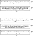
- the target electronic device is controlled to perform a first stage of constant voltage charging with a first cut-off voltage, in response to detecting that constant current charging of the target electronic device ends.
- the target electronic device when the target electronic device detects a charging signal, for example, when the target electronic device detects that it is connected to a power adapter (which can be generally referred to as a charger), the target electronic device may detect whether its own battery voltage is greater than or equal to a first preset voltage threshold.
- the first preset voltage threshold may be a boot voltage, and the so-called “boot voltage” refers to a minimum battery voltage that can ensure the normal boot of the target electronic device.
- the target electronic device can directly enter the constant current charging stage.
- the constant current charging stage refers to a process of charging the battery with a fixed charging current.
- the target electronic device is charged with a target charging current in the constant current charging stage.
- the target electronic device may enter a pre-charging stage, in which the target electronic device is charged with a small charging current until the battery voltage of the target electronic device reaches the first preset voltage threshold, at that time, the pre-charging stage ends. After the pre-charging stage, the target electronic device can enter the constant current charging stage. As described above, in the embodiments of the present disclosure, the target electronic device is charged with the target charging current in the constant current charging stage.
- the magnitude of the target charging current mentioned above may be determined by the target electronic device according to its own battery temperature and the type of the power adapter connected thereto. The method of determining the magnitude of the target charging current is described in detail below.
- the target electronic device cannot be always charged in the constant current charging stage, otherwise, the battery voltage of the target electronic device will continuously increase which would cause damage to the battery of the target electronic device. Therefore, in order to ensure the safety of the battery of the target electronic device, optionally, the target electronic device may periodically detect its own battery voltage during the constant current charging process. When it is detected that its own battery voltage is greater than or equal to a first cut-off voltage, the target electronic device needs to stop performing the constant current charging. The first cut-off voltage is greater than a rated voltage of the battery of the target electronic device.
- the battery of the target electronic device After the constant current charging stage ends, the battery of the target electronic device is generally not fully charged.
- the target electronic device In order to make the battery of the target electronic device to be fully charged, the target electronic device can be controlled to perform constant voltage charging.
- the so-called constant voltage charging refers to a process of charging the battery with a fixed charging voltage.
- the target electronic device can perform the constant voltage charging in two stages.
- the target electronic device is charged with the first cut-off voltage, where the first cut-off voltage is the battery voltage of the target electronic device that is obtained at the end of the constant current charging stage. That is, the first cut-off voltage is a boundary voltage between the constant current charging stage and the constant voltage charging stage.
- the process of the second stage of constant voltage charging is described in detail below.
- the first cut-off voltage may be determined by the target electronic device according to its own battery temperature.
- a first voltage look-up table may be maintained in the target electronic device, and the first voltage look-up table may store correspondences between the battery voltages to be reached at the end of the constant current charging stage and the battery temperatures.
- the target electronic device may query the first voltage look-up table according to the current battery temperature, to obtain the battery voltage (that is, the first cut-off voltage) to be reached at the end of the constant current charging stage and corresponding to the current battery temperature.
- the first cut-off voltage may be greater than a second preset voltage threshold.
- the second preset voltage threshold may be set according to the rated voltage of the battery of the target electronic device. In actual applications, the second preset voltage threshold may be 20-30 mV higher than the rated voltage. In other words, the first cut-off voltage may be set to be relatively large. Since the first cut-off voltage is set to be relatively large, the duration of the constant current charging stage of the target electronic device is relatively long; and after the constant current charging stage ends, the battery level of the target electronic device is relatively high, which enables the duration of the subsequent constant voltage charging process to be shortened, thereby shortening the total charging time of the battery of the target electronic device.
- the target electronic device is controlled to perform a second stage of constant voltage charging with a second cut-off voltage, in response to detecting that the first stage of constant voltage charging ends.
- the target electronic device may enter the second stage of constant voltage charging, where the charging voltage (that is, the second cut-off voltage) of the second stage of constant voltage charging is less than the charging voltage (that is, the first cut-off voltage) of the first stage of constant voltage charging.
- the second cut-off voltage may also be determined by the target electronic device according to its own battery temperature.
- a second voltage look-up table may be maintained in the target electronic device, and the second voltage look-up table may store correspondences between the charging voltages of the second stage of constant voltage charging and the battery temperatures.
- the target electronic device may query the second voltage look-up table according to the current battery temperature, to obtain the charging voltage (that is, the second cut-off voltage) of the second stage of constant voltage charging that corresponds to the current battery temperature.
- the second stage of constant voltage charging Since the charging voltage of the second stage of constant voltage charging is relatively small, the charging current decreases relatively fast during the second stage of constant voltage charging. Therefore, the second stage of constant voltage charging lasts for a relatively short period of time.
- the two-stage constant voltage charging way provided by the embodiments of the present disclosure enables the duration of the entire constant voltage charging process to be shortened, thereby shortening the total charging time of the battery.
- FIG. 2 a schematic diagram illustrating a charging curve F1 of the traditional one-stage constant voltage charging way and a charging curve F2 of the two-stage constant voltage charging way provided by the embodiments of the present disclosure is shown.
- the horizontal axis represents time in unit of minutes (min), and the vertical axis represents the charging current in unit of mA.
- the charging curve F1 of the one-stage constant voltage charging way and the charging curve F2 of the two-stage constant voltage charging way have an overlapped portion corresponding to the constant current charging stage H.
- the two-stage constant voltage charging process includes the first stage of constant voltage charging J1 and the second stage of constant voltage charging J2.
- the charging current of the second stage of constant voltage charging J2 decreases faster, for reasons as follows. After the first stage of constant voltage charging J1 ends, the battery is generally close to get a full charge, that is, the battery voltage is already relatively high and has a small difference from the first cut-off voltage (the charging voltage of the first stage of constant voltage charging).
- the charging current is related to the difference between the charging voltage and the battery voltage, specifically, the greater the difference, the faster the charging current decreases, and the smaller the difference, the slower the charging current decreases.
- the charging current decreases slowly.
- the charging voltage (that is, the second cut-off voltage) of the second stage of constant voltage charging J2 is lower than the charging voltage (that is, the first cut-off voltage) of the first stage of constant voltage charging, the difference between the charging voltage of the second stage of constant voltage charging J2 and the battery voltage is relatively large, and accordingly, the charging current decreases relatively fast.
- the duration of the second stage of constant voltage charging J2 is relatively short, which enables the duration of the entire constant voltage charging process to be short.
- the charging current decreases slowly as a whole, and the duration of the entire constant voltage charging process is relatively long.
- the duration t1 of the constant current charging stage is longer than the duration t2 of the traditional constant current charging stage. In this way, after the constant current charging stage ends, the battery level of the target electronic device is relatively high, which enables the duration of the subsequent constant voltage charging process to be shortened, thereby shortening the total charging time of the battery of the target electronic device.
- the target electronic device after the second stage of constant voltage charging ends, it can be considered that the battery of the target electronic device has been fully charged. At this time, the target electronic device can be controlled to stop charging.
- the target electronic device is controlled to perform the first stage of constant voltage charging with the first cut-off voltage after the constant current charging stage ends. Then, when it is detected that the first stage of constant voltage charging ends, the target electronic device is controlled to perform the second stage of constant voltage charging with the second cut-off voltage, where the second cut-off voltage is less than the first cut-off voltage.
- the constant voltage charging process of the target electronic device is divided into two stages with the charging voltage (that is, the second cut-off voltage) of the second stage of constant voltage charging being relatively small, the charging current decreases fast in the second stage of constant voltage charging. Therefore, the second stage of constant voltage charging lasts for a short period of time.
- the charging method provided in the embodiments of the present disclosure can shorten the duration of the entire constant voltage charging process, thus shortening the total charging time of the battery.
- the operation of determining that the first stage of constant voltage charging of the target electronic device ends may include operations as follows.
- the stage switching condition refers to a condition for switching from the first stage of constant voltage charging to the second stage of constant voltage charging.
- the stage switching condition may be set according to the charging current within the first stage of constant voltage charging and a first cut-off current.
- the stage switching condition may be set according to the relationship between the magnitudes of the charging current and the first cut-off current.
- the stage switching condition may be set according to whether the charging current is less than or equal to the first cut-off current.
- the first cut-off current may be determined by the target electronic device according to its own battery temperature.
- a first current look-up table may be maintained in the target electronic device, and the first current look-up table may store correspondences between the cut-off currents corresponding to the stage switching condition and the battery temperatures.
- the target electronic device may query the first current look-up table according to the current battery temperature, to obtain the first cut-off current corresponding to the current battery temperature.
- the current charging state of the target electronic device may be determined according to the relationship between the magnitudes of the charging current and a certain current threshold.
- the target electronic device may periodically detect its own charging current, and the target electronic device can determine whether the charging state meets the stage switching conditions by determining whether the charging current is less than or equal to the first cut-off current.
- the target electronic device when the number of times, that the target electronic device detects that its own charging current is less than or equal to the first cut-off current, is greater than or equal to a first number threshold, it may be determined that the charging state of the target electronic device meets the stage switching condition.
- the target electronic device does not determine that its own charging state meets the stage switching condition once it detects that the charging current is less than or equal to the first cut-off current. Rather, the target electronic device determines that its own charging state meets the stage switching condition, only when the number of times, that the target electronic device detects that its own charging current is less than or equal to the first cut-off current, is greater than or equal to the first number threshold. Therefore, the influence of accidental factors on determining whether the charging state meets the stage switching condition can be sufficiently reduced, and the accuracy of determining that the charging state meets the stage switching condition can be improved.
- the target electronic device may increase the number of times of first detections by 1 (the initial value of the number of times of the first detections is 0).
- the target electronic device can determine that its own charging state meets the stage switching condition.
- the operation of determining that the second stage of constant voltage charging ends may include operations as follows.
- the charging cut-off condition refers to a condition for switching from the second stage of constant voltage charging to stopping charging.
- the charging cut-off condition may be set according to the charging current and a second cut-off current.
- the charging cut-off condition may be set according to the relationship between the magnitudes of the charging current and the second cut-off current.
- the charging cut-off condition may be set according to whether the charging current within the second stage of constant voltage charging is less than or equal to the second cut-off current.
- the second cut-off current is less than the first cut-off current.
- the second cut-off current may be determined by the target electronic device according to its own battery temperature.
- a second current look-up table may be maintained in the target electronic device, and the second current look-up table may store correspondences between the cut-off currents corresponding to the charging cut-off condition and the battery temperatures.
- the target electronic device may query the second current look-up table according to the current battery temperature, to obtain the second cut-off current corresponding to the current battery temperature.
- the target electronic device may periodically detect its own charging current, and the target electronic device may determine whether the charging state meets the charging cut-off condition by determining whether the charging current is less than or equal to the second cut-off current.
- the number of times, that the charging current of the target electronic device is detected to be less than or equal to the second cut-off current, is greater than or equal to a second number threshold it may be determined that the charge state of the target electronic device meets the charging cut-off condition.
- the target electronic device does not determine that its own charging state meets the charging cut-off condition once it detects that the charging current is less than or equal to the second cut-off current. Rather, the target electronic device determines that its own charging state meets the charging cut-off condition, only when the number of times, that the target electronic device detects that its own charging current is less than or equal to the second cut-off current, is greater than or equal to the second time threshold. Therefore, the influence of accidental factors on determining whether the charging state meets the charging cut-off condition can be sufficiently reduced, and the accuracy of determining that the charging state meets the charging cut-off condition can be improved.
- the target electronic device may increase the number of times of second detections by 1 (the initial value of the number of times of the second detections is 0).
- the target electronic device can determine that its own charging state meets the charging cut-off condition.
- the target electronic device can enter the second stage of constant voltage charging in which the charging current decreases relatively fast. Since the charging current decreases fast in the second stage of constant voltage charging, a small second cut-off current may be set for the second stage of constant voltage charging, so that the battery of the target electronic device can be charged more fully without significantly increasing the charging time.
- the first cut-off current is set to be relatively large, the duration of the first stage of constant voltage charging in which the charging current decreases relatively slowly can be shortened, so that the target electronic device can quickly enter the second stage of constant voltage charging in which the charging current decreases relatively fast. Since the second cut-off current is set to be relatively small, and the charging current of the second stage of constant voltage charging decreases relatively fast, the battery of the target electronic device can be charged more fully without significantly increasing the charging time.
- the target electronic device can stop charging.
- the target electronic device may be controlled to display information indicating that the battery is fully charged and that the charging of the target electronic device ends.
- the target electronic device In the traditional charging technology, once the target electronic device detects that its battery level reaches 100% during the charging, it displays the information indicating that the battery is fully charged. However, at the time instant the battery level reaches 100%, the target electronic device is usually still in the constant voltage charging stage. That is, at the time instant the battery level reaches 100%, the charging of the target electronic device has not stopped yet. In this case, if the user disconnects the power adapter from the electronic device based on the information indicating that the battery is fully charged, the charging of the target electronic device is terminated, causing the battery level of the target electronic device not to be sufficiently full, which in turn affects the standby time of the target electronic device.
- the target electronic device may not display the information indicating that the battery is fully charged, once detecting the battery level reaches 100% during the charging. Rather, the target electronic device displays the information indicating that the battery is fully charged, only after the target electronic device stops charging, that is, only after the two stages of constant voltage charging of the target electronic device end. In this way, the user will not be misled to disconnect the power adapter from the target electronic device when the target electronic device has not stopped charging yet. Accordingly, the battery level of the target electronic device can be charged to be sufficient full, and the standby time of the target electronic device can be ensured.
- the embodiments of the present disclosure provide an exemplary method for determining the magnitude of the target charging current.
- the target charging current refers to the charging current adopted in the constant current charging stage of the target electronic device.
- the method can be applied to the target electronic device.
- the method may be executed by the charging control chip in the target electronic device. As shown in FIG. 5 , the method may include operations as follows.
- the type of the power adapter connected to the target electronic device and the battery temperature of the target electronic device are acquired.
- the target electronic device may be compatible with multiple types of power adapters.
- the charging currents that can be output by different types of power adapters are generally different. For example, some types of power adapters can output a charging current of 4A, and some types of power adapters can output a charging current of 6A. Therefore, when determining the charging current for the constant current charging stage of the target electronic device, the type of the power adapter connected to the target electronic device needs to be considered.
- the target electronic device and the power adapter may be connected through a Universal Serial Bus (USB) interface, and the target electronic device may read the type of the power adapter through the USB interface.
- USB Universal Serial Bus
- the target electronic device may detect its own battery temperature through a temperature sensor.
- a first charging current corresponding to the type of the power adapter is determined, and a second charging current corresponding to the battery temperature of the target electronic device is determined.
- a third current look-up table and a fourth current look-up table may be maintained in the target electronic device.
- the third current look-up table may store correspondences between the types of the power adapters and the charging currents
- the fourth current look-up table may store correspondences between the battery temperatures and the charging currents.
- the target electronic device may query the third current look-up table according to the acquired type of the power adapter, to obtain the first charging current corresponding to the acquired type of the power adapter.
- the target electronic device may query the fourth current look-up table according to the acquired battery temperature, to obtain the second charging current corresponding to the acquired battery temperature.
- a smaller one of the first charging current and the second charging current is determined as the target charging current.
- the target charging current refers to the charging current adopted for the constant current charging stage of the target electronic device.
- the target electronic device can obtain a smaller charging current from the first charging current and the second charging current. For example, if the first charging current is 4A and the second charging current is 9A, the target electronic device can obtain the smaller charging current of 4A that equals to the first charging current.
- the target electronic device may determine the smaller charging current as the target charging current. Since the target electronic device uses the smaller charging current of the first charging current and the second charging current as the target charging current, the target charging current can be compatible with both the type of the power adapter and the battery temperature, making the determined target charging current more accurate.
- the embodiments of the present disclosure provide an exemplary method for determining the second cut-off voltage and the second cut-off current.
- the method can be applied to the target electronic device.
- the method may be executed by the charging control chip in the target electronic device.
- the method may include operations as follows.
- the battery level of the target electronic device is detected, in response to detecting that the first stage of constant voltage charging ends.
- the battery temperature affects the battery level during the charging process.
- the battery levels are different, when the battery is charged at the same charging current and different battery temperatures for the same length of time.
- the battery levels are also different, when the battery is charged at the same charging voltage and different battery temperatures for the same length of time.
- the battery level of the target electronic device may not a fixed value, but fluctuates according to the battery temperature. In this way, there will be such a situation that the battery level of the target electronic device may not be as full as expected after the first stage of constant voltage charging ends. At this time, it is necessary to charge more power to the battery of the target electronic device through the second stage of constant voltage charging, to make up for the insufficiency of the battery level in the previous charging stage.
- the target electronic device when it is detected that the charging state of the target electronic device meets the stage switching condition, that is, when the target electronic device can be switched from the first stage of constant voltage charging to the second stage of constant voltage charging, the target electronic device can detect its own battery level.
- the second cut-off voltage and the second cut-off current are determined according to the battery level of the target electronic device.
- the target electronic device After acquiring the battery level of the target electronic device at the end of the first stage of constant voltage charging, the target electronic device can determine the second cut-off voltage and the second cut-off current according to the acquired battery level, so that the insufficiency of the battery level of the previous charging stage can be compensated through the second stage of constant voltage charging in a case where the battery level of the target electronic device is not as full as expected after the first stage of constant voltage charging ends.
- the target electronic device may determine the second cut-off voltage and the second cut-off current according to both the battery temperature and the battery level.
- FIG. 4, and FIG. 5 are shown in sequence as indicated by the arrows, these operations are not necessarily performed in sequence in the order indicated by the arrows. Unless specifically stated in this disclosure, the execution of these operations is not strictly limited in order, and these operations can be executed in other orders. Moreover, at least some of the operations in FIG. 1 , FIG. 3 , FIG. 4, and FIG. 5 may include multiple sub-operations or multiple stages. These sub-operations or stages are not necessarily executed at the same time instant, but can be executed at different time instants. The sub-operations or stages may not necessarily performed sequentially in order, but may be performed alternately with other operations or at least a part of the sub-operations or stages of other operations.
- the process may include operations as follows.
- the process is started.
- it is determined whether the target electronic device is equipped with a plug-in for the two-stage constant voltage charging; if not, operation 703 is performed; and if yes, operation 704 is performed.
- the charging voltage and the cut-off current for the constant voltage charging stage are set, and one-stage constant voltage charging is performed.
- the type of the power adapter is identified.
- the charging voltage (that is, the first cut-off voltage) of the first stage of constant voltage charging and the cut-off current (that is, the first cut-off current) of the first stage of constant voltage charging are set.
- an adaptive operation is performed for of the input current.
- the battery temperature is acquired.
- the charging current of the constant current charging stage is set according to the battery temperature and the type of the power adapter.
- other charging function thread operations are performed.
- the constant current charging is performed.
- the first stage of constant voltage charging is performed.
- the first stage of constant voltage charging is performed.
- the charging voltage (that is, the second cut-off voltage) of the second stage of constant voltage charging and the cut-off current (that is, the second cut-off current) of the second stage of constant voltage charging are set.
- the charging process is stopped.
- FIG. 8 a block diagram of a charging apparatus 700 provided by embodiments of the present disclosure is illustrated.
- the charging apparatus 700 may be configured in the target electronic device described above.
- the charging apparatus 700 may include a first control module 701 and a second control module 702.
- the first control module 701 is configured to control the target electronic device to perform a first stage of constant voltage charging with a first cut-off voltage, when it is detected that constant current charging of the target electronic device ends.
- the second control module 702 is configured to control the target electronic device to perform a second stage of constant-voltage charging with a second cut-off voltage, when it is detected that the first stage of constant-voltage charging ends, where the second cut-off voltage is less than the first cut-off voltage.
- the embodiments of the present disclosure also provides another charging apparatus 800.
- the charging apparatus 800 may optionally include a first detection module 703, a third control module 704, a second detection module 705, a display module 706, a third detection module 707, a first determination module 708, an acquisition module 709, a second determination module 710, a third determination module 711, and a fourth detection module 712.
- the first detection module 703 is configured to detect whether the charging state of the target electronic device meets a stage switching condition, the stage switching condition being set according to a charging current and a first cut-off current; and determine that the first stage of constant voltage charging ends, when it is detected that the charging state of the target electronic device meets the stage switching condition.
- the first detection module 703 is specifically configured to: periodically detect the charging current of the target electronic device; and determine whether the charging current of the target electronic device is less than or equal to the first cut-off current, to determine whether the charging state of the target electronic device meets the stage switching condition.
- the first detection module 703 is specifically configured to: determine that the charging state of the target electronic device meets the stage switching condition, when the number of times, that the charging current of the target electronic device is detected to be less than or equal to the first cut-off current, is greater than or equal to a first number threshold.
- the third control module 704 is configured to control the target electronic device to stop charging, when it is detected that the second stage of constant voltage charging ends.
- the second detection module 705 is configured to detect whether the charging state of the target electronic device meets a charging cut-off condition, the charging cut-off condition being set according to the charging current and a second cut-off current, and the second cut-off current being less than the first cut-off current; and determine that the second stage of constant voltage charging ends, when it is detected that the charging state of the target electronic device meets the charging cut-off condition.
- the second detection module 705 is specifically configured to: periodically detect the charging current of the target electronic device; and determine whether the charging current of the target electronic device is less than or equal to the second cut-off current, to determine whether the charging state of the target electronic device meets the charging cut-off condition.
- the second detection module 705 is specifically configured to: determine that the charging state of the target electronic device meets the charging cut-off condition, when the number of times, that the charging current of the target electronic device is detected to be less than or equal to the second cut-off current, is greater than or equal to a second number threshold.
- the display module 706 is configured to control the target electronic device to display information indicating that the battery is fully charged and that the charging of the target electronic device ends.
- the third detection module 707 is configured to detect a battery level of the target electronic device, when it is detected that the first stage of constant voltage charging ends.
- the first determination module 708 is configured to determine the second cut-off voltage and the second cut-off current according to the battery level of the target electronic device.
- the acquisition module 709 is configured to acquire the type of the power adapter connected to the target electronic device and the battery temperature of the target electronic device.
- the second determination module 710 is configured to: determine a first charging current corresponding to the type of the power adapter, and determine a second charging current corresponding to the battery temperature of the target electronic device.
- the third determination module 711 is configured to determine a smaller one of the first charging current and the second charging current as the charging current for the constant current charging of the target electronic device.
- the fourth detection module 712 is configured to: periodically detect the battery voltage of the target electronic device; and determine that the constant current charging of the target electronic device ends, when it is detected that the battery voltage of the target electronic device is greater than or equal to the first cut-off voltage, where the first cut-off voltage is greater than a rated voltage of the battery of the target electronic device.
- the charging apparatus provided in the embodiments of the present disclosure can implement the foregoing method embodiments, and its implementation principles and technical effects are similar to those in the method embodiments, which will not be repeated here.
- Each module in the above-mentioned charging apparatus can be implemented in whole or in part by software, hardware, or a combination thereof.
- the foregoing modules may be embedded in the form of hardware into the processor of the computer device or independent of the processor, or may be stored in the memory of the computer device in the form of software, so that the processor can call and execute them to implement the operations corresponding to the foregoing modules.
- an electronic device may be a notebook computer, a smart phone, a tablet computer, a wearable device, and the like, and its internal structure may be as shown in FIG. 10 .
- the electronic device includes a processor, a memory, a network interface, a display screen and an input device connected through a system bus. Among them, the processor of the electronic device is used to provide calculation and control capabilities.
- the memory of the electronic device includes a non-volatile storage medium and an internal memory.
- the non-volatile storage medium stores an operating system and computer programs.
- the internal memory provides an environment for the operation of the operating system and computer programs in the non-volatile storage medium.
- the network interface of the electronic device is used for communication with an external terminal through a network connection.
- the computer program is executed by the processor to realize the charging method.
- the display screen of the electronic device may be a liquid crystal display screen or an electronic ink display screen.
- the input device of the electronic device may be a touch layer covered on the display screen, or a button, trackball or touch pad set on the housing of the electronic device, and it can also be an external keyboard, touchpad, or mouse.
- FIG. 10 is only a block diagram illustrating a part of the structures related to the solution of the present disclosure, and does not limiting the electronic device to which the solution of the present disclosure is applied.
- the specific electronic device may include more or fewer parts than those shown in the figure, or combining some of the parts, or having a different arrangement of the parts.
- an electronic device in the embodiments of the present disclosure, includes a memory and a processor, and a computer program is stored in the memory.
- the processor implements the following operations when executing the computer program: controlling a target electronic device to perform a first stage of constant voltage charging with a first cut-off voltage, in response to detecting that constant current charging of the target electronic device ends; and controlling the target electronic device to perform a second stage of constant voltage charging with a second cut-off voltage, in response to detecting that the first stage of constant voltage charging ends, where the second cut-off voltage is less than the first cut-off voltage.
- the processor further implements the following operations when executing the computer program: detecting whether a charging state of the target electronic device meets a stage switching condition, where the stage switching condition is set according to a charging current and a first cut-off current; and determining that the first stage of constant voltage charging ends, in response to detecting that the charging state of the target electronic device meets the stage switching condition.
- the processor further implements the following operations when executing the computer program: periodically detecting the charging current of the target electronic device; and determining whether the charging current of the target electronic device is less than or equal to the first cut-off current, to determine whether the charging state of the target electronic device meets the stage switching condition.
- the processor further implements the following operations when executing the computer program: determining that the charging state of the target electronic device meets the stage switching condition, in response to detecting that the number of times, that the charging current of the target electronic device is detected to be less than or equal to the first cut-off current, is greater than or equal to a first number threshold.
- the processor further implements the following operations when executing the computer program: controlling the target electronic device to stop charging, in response to detecting that the second stage of constant voltage charging ends.
- the processor further implements the following operations when executing the computer program: detecting whether the charging state of the target electronic device meets a charging cut-off condition, where the charging cut-off condition is set according to the charging current and a second cut-off current, and the second cut-off current is less than the first cut-off current; and determining that the second stage of constant voltage charging ends, in response to detecting that the charging state of the target electronic device meets the charging cut-off condition.
- the processor further implements the following operations when executing the computer program: periodically detecting the charging current of the target electronic device; and determining whether the charging current of the target electronic device is less than or equal to the second cut-off current, to determine whether the charging state of the target electronic device meets the charging cut-off condition.
- the processor further implements the following operations when executing the computer program: determining that the charging state of the target electronic device meets the charging cut-off condition, in response to detecting that the number of times, that the charging current of the target electronic device is detected to be less than or equal to the second cut-off current, is greater than or equal to a second number threshold.
- the processor further implements the following operations when executing the computer program: detecting a battery level of the target electronic device in response to detecting that the first stage of constant voltage charging ends; and determining the second cut-off voltage and the second cut-off current according to the battery level of the target electronic device.
- the processor further implements the following operations when executing the computer program: controlling the target electronic device to display information indicating that a battery of the target electronic device is fully charged and that the charging of the target electronic device ends.
- the processor further implements the following operations when executing the computer program: acquiring a type of a power adapter connected to the target electronic device and a battery temperature of the target electronic device; determining a first charging current corresponding to the type of the power adapter, and determining a second charging current corresponding to the battery temperature of the target electronic device; and determining a smaller one of the first charging current and the second charging current as the charging current for the constant current charging of the target electronic device.
- the processor further implements the following operations when executing the computer program: periodically detecting a battery voltage of the target electronic device; and determining that the constant current charging of the target electronic device ends, in response to detecting that the battery voltage of the target electronic device is greater than or equal to a first cut-off voltage, where the first cut-off voltage is greater than a rated voltage for the battery of the target electronic device.
- a computer-readable storage medium on which a computer program is stored.
- the following operations are caused to be implemented: controlling a target electronic device to perform a first stage of constant voltage charging with a first cut-off voltage, in response to detecting that constant current charging of the target electronic device ends; and controlling the target electronic device to perform a second stage of constant voltage charging with a second cut-off voltage, in response to detecting that the first stage of constant voltage charging ends, where the second cut-off voltage is less than the first cut-off voltage.
- the following operations are further implemented: detecting whether a charging state of the target electronic device meets a stage switching condition, where the stage switching condition is set according to a charging current and a first cut-off current; and determining that the first stage of constant voltage charging ends, in response to detecting that the charging state of the target electronic device meets the stage switching condition.
- the following operations are further implemented: periodically detecting the charging current of the target electronic device; and determining whether the charging current of the target electronic device is less than or equal to the first cut-off current, to determine whether the charging state of the target electronic device meets the stage switching condition.
- the following operations are further implemented: determining that the charging state of the target electronic device meets the stage switching condition, in response to detecting that the number of times, that the charging current of the target electronic device is detected to be less than or equal to the first cut-off current, is greater than or equal to a first number threshold.
- the following operations are further implemented: controlling the target electronic device to stop charging, in response to detecting that the second stage of constant voltage charging ends.
- the following operations are further implemented: detecting whether the charging state of the target electronic device meets a charging cut-off condition, where the charging cut-off condition is set according to the charging current and a second cut-off current, and the second cut-off current is less than the first cut-off current; and determining that the second stage of constant voltage charging ends, in response to detecting that the charging state of the target electronic device meets the charging cut-off condition.
- the following operations are further implemented: periodically detecting the charging current of the target electronic device; and determining whether the charging current of the target electronic device is less than or equal to the second cut-off current, to determine whether the charging state of the target electronic device meets the charging cut-off condition.
- the following operations are further implemented: determining that the charging state of the target electronic device meets the charging cut-off condition, in response to detecting that the number of times, that the charging current of the target electronic device is detected to be less than or equal to the second cut-off current, is greater than or equal to a second number threshold.
- the following operations are further implemented: detecting a battery level of the target electronic device in response to detecting that the first stage of constant voltage charging ends; and determining the second cut-off voltage and the second cut-off current according to the battery level of the target electronic device.
- the following operations are further implemented: controlling the target electronic device to display information indicating that a battery of the target electronic device is fully charged and that the charging of the target electronic device ends.
- the following operations are further implemented: acquiring a type of a power adapter connected to the target electronic device and a battery temperature of the target electronic device; determining a first charging current corresponding to the type of the power adapter, and determining a second charging current corresponding to the battery temperature of the target electronic device; and determining a smaller one of the first charging current and the second charging current as the charging current for the constant current charging of the target electronic device.
- the following operations are further implemented: periodically detecting a battery voltage of the target electronic device; and determining that the constant current charging of the target electronic device ends, in response to detecting that the battery voltage of the target electronic device is greater than or equal to a first cut-off voltage, where the first cut-off voltage is greater than a rated voltage for the battery of the target electronic device.
- the memory, storage, database or other media referred in the embodiments provided by the disclosure may include non-volatile and/or volatile memories.
- the non-volatile memory may include read only memory (ROM), programmable ROM (PROM), electrically programmable ROM (EPROM), electrically erasable programmable ROM (EEPROM), or flash memory.
- the volatile memory may include random access memory (RAM) or external cache memory.
- RAM is available in many forms, such as static RAM (SRAM), dynamic RAM (DRAM), synchronous DRAM (SDRAM), double data rate SDRAM (DDRSDRAM), enhanced SDRAM (ESDRAM), Synchlink DRAM (SLDRAM), Rambus direct RAM (RDRAM), direct Rambus dynamic RAM (DRDRAM), and Rambus dynamic RAM (RDRAM), etc.
- SRAM static RAM
- DRAM dynamic RAM
- SDRAM synchronous DRAM
- DDRSDRAM double data rate SDRAM
- ESDRAM enhanced SDRAM
- SLDRAM Synchlink DRAM
- RDRAM Rambus direct RAM
- DRAM direct Rambus dynamic RAM
- RDRAM Rambus dynamic RAM
Landscapes
- Engineering & Computer Science (AREA)
- Power Engineering (AREA)
- Manufacturing & Machinery (AREA)
- Chemical & Material Sciences (AREA)
- Chemical Kinetics & Catalysis (AREA)
- Electrochemistry (AREA)
- General Chemical & Material Sciences (AREA)
- Charge And Discharge Circuits For Batteries Or The Like (AREA)
- Secondary Cells (AREA)
Applications Claiming Priority (2)
| Application Number | Priority Date | Filing Date | Title |
|---|---|---|---|
| CN201911031329.3A CN110729790B (zh) | 2019-10-28 | 2019-10-28 | 充电方法、装置、计算机设备与存储介质 |
| PCT/CN2020/121078 WO2021082934A1 (fr) | 2019-10-28 | 2020-10-15 | Procédé et appareil de charge, dispositif informatique et support de stockage |
Publications (2)
| Publication Number | Publication Date |
|---|---|
| EP4007116A1 true EP4007116A1 (fr) | 2022-06-01 |
| EP4007116A4 EP4007116A4 (fr) | 2022-11-09 |
Family
ID=69222269
Family Applications (1)
| Application Number | Title | Priority Date | Filing Date |
|---|---|---|---|
| EP20881763.5A Pending EP4007116A4 (fr) | 2019-10-28 | 2020-10-15 | Procédé et appareil de charge, dispositif informatique et support de stockage |
Country Status (4)
| Country | Link |
|---|---|
| US (1) | US20220285967A1 (fr) |
| EP (1) | EP4007116A4 (fr) |
| CN (1) | CN110729790B (fr) |
| WO (1) | WO2021082934A1 (fr) |
Families Citing this family (13)
| Publication number | Priority date | Publication date | Assignee | Title |
|---|---|---|---|---|
| CN110729790B (zh) * | 2019-10-28 | 2023-03-21 | Oppo广东移动通信有限公司 | 充电方法、装置、计算机设备与存储介质 |
| CN111371140B (zh) * | 2020-03-11 | 2024-03-29 | Oppo广东移动通信有限公司 | 充电控制方法、装置、终端设备以及存储介质 |
| CN111384757B (zh) * | 2020-04-08 | 2022-06-14 | Oppo广东移动通信有限公司 | 充电方法、装置、设备及存储介质 |
| CN113571787B (zh) * | 2020-04-29 | 2023-04-07 | 北京小米移动软件有限公司 | 一种锂离子电池的充电方法 |
| CN114388911B (zh) * | 2020-10-16 | 2024-08-13 | Oppo广东移动通信有限公司 | 充电方法、电子设备和可读存储介质 |
| CN112952883B (zh) * | 2021-04-22 | 2023-02-07 | 国网甘肃省电力公司电力科学研究院 | 一种分布式储能系统的充电控制方法及系统 |
| CN113315196A (zh) * | 2021-05-26 | 2021-08-27 | 闻泰通讯股份有限公司 | 恒流充电控制方法、装置、电子设备和存储介质 |
| CN113364089A (zh) * | 2021-06-03 | 2021-09-07 | 珠海市魅族科技有限公司 | 充电方法、装置、电子设备、存储介质以及充电电路 |
| CN114336891A (zh) * | 2022-01-14 | 2022-04-12 | 深圳市晶讯技术股份有限公司 | 基于线材压降补偿的快速充电控制方法、装置和相关设备 |
| CN116961149A (zh) * | 2022-04-13 | 2023-10-27 | Oppo广东移动通信有限公司 | 充电方法、装置、电子设备和计算机可读存储介质 |
| CN115864597A (zh) * | 2022-12-29 | 2023-03-28 | 联想(北京)有限公司 | 充电方法、装置、充电电路、电子设备及存储介质 |
| CN117096991B (zh) * | 2023-10-08 | 2024-04-19 | 荣耀终端有限公司 | 一种充电方法、电子设备及可读存储介质 |
| CN118868333B (zh) * | 2024-09-24 | 2025-03-04 | 宁德时代新能源科技股份有限公司 | 充电方法及装置、电子设备及可读存储介质 |
Family Cites Families (110)
| Publication number | Priority date | Publication date | Assignee | Title |
|---|---|---|---|---|
| US4016473A (en) * | 1975-11-06 | 1977-04-05 | Utah Research & Development Co., Inc. | DC powered capacitive pulse charge and pulse discharge battery charger |
| US4152635A (en) * | 1977-07-14 | 1979-05-01 | Research Development Systems, Inc. | Battery charger |
| US4396880A (en) * | 1981-06-05 | 1983-08-02 | Firing Circuits Inc. | Method and apparatus for charging a battery |
| CA1159110A (fr) * | 1981-07-22 | 1983-12-20 | Alfred M. Hase | Redresseur de charge d'entretien a deux regimes de tension constante et dispositif de surveillance d'accumulateur |
| CA1209205A (fr) * | 1984-11-02 | 1986-08-05 | Alfred M. Hase | Circuits a auto-excitation et coupure magnetique, respectivement, pour le chargement des accumulateurs et le controle du niveau de charge |
| DE3732339A1 (de) * | 1987-09-25 | 1989-04-13 | Varta Batterie | Ladeverfahren fuer wartungsfreie bleibatterien mit festgelegtem elektrolyten |
| US5185566A (en) * | 1990-05-04 | 1993-02-09 | Motorola, Inc. | Method and apparatus for detecting the state of charge of a battery |
| US5111131A (en) * | 1990-11-30 | 1992-05-05 | Burr-Brown Corporation | Compact low noise low power dual mode battery charging circuit |
| US5442274A (en) * | 1992-08-27 | 1995-08-15 | Sanyo Electric Company, Ltd. | Rechargeable battery charging method |
| JP3428015B2 (ja) * | 1992-10-23 | 2003-07-22 | ソニー株式会社 | バッテリーパック |
| DE4414134A1 (de) * | 1993-05-03 | 1994-11-10 | Dial Engineering Ag | Verfahren zum Laden von verschlossenen Bleibatterien |
| JP3286456B2 (ja) * | 1994-02-28 | 2002-05-27 | 三洋電機株式会社 | 二次電池の充電方法 |
| US5572110A (en) * | 1994-12-15 | 1996-11-05 | Intel Corporation | Smart battery charger system |
| US5630027A (en) * | 1994-12-28 | 1997-05-13 | Texas Instruments Incorporated | Method and apparatus for compensating horizontal and vertical alignment errors in display systems |
| US5670863A (en) * | 1995-02-07 | 1997-09-23 | Benchmarq Microelectronics, Inc. | Lead acid charger with ratioed time-out periods and current pulse mode of operation |
| US6104165A (en) * | 1995-06-16 | 2000-08-15 | Zip Charge Corporation | Multi-stage battery charging system |
| JP3620118B2 (ja) * | 1995-10-24 | 2005-02-16 | 松下電器産業株式会社 | 定電流・定電圧充電装置 |
| US5684387A (en) * | 1996-08-15 | 1997-11-04 | Motorola, Inc. | Voltage cutoff compensation method for a battery in a charger |
| JP3628123B2 (ja) * | 1996-08-21 | 2005-03-09 | シチズン時計株式会社 | 充電式電子時計 |
| US6181103B1 (en) * | 1997-05-27 | 2001-01-30 | Shu-Chin Chen | Advanced intelligent computer power management system |
| US5994878A (en) * | 1997-09-30 | 1999-11-30 | Chartec Laboratories A/S | Method and apparatus for charging a rechargeable battery |
| US6275006B1 (en) * | 1998-05-27 | 2001-08-14 | Matsushita Electric Industrial Co., Ltd. | Method for charging secondary battery |
| US6333619B1 (en) * | 2000-03-15 | 2001-12-25 | Jaime H Chavez | Cyclical battery charger with incremental and decremental current and a method of operation thereof |
| EP1291999B1 (fr) * | 2000-04-13 | 2013-01-30 | Makita Corporation | Adaptateur pour chargeur de batterie |
| JP4165037B2 (ja) * | 2001-06-08 | 2008-10-15 | 株式会社デンソー | 携帯型読取装置 |
| TW530429B (en) * | 2001-12-24 | 2003-05-01 | Avid Electronics Corp | Intelligent secondary battery management method and device |
| CN106099218B (zh) * | 2003-11-24 | 2019-05-17 | 密尔沃基电动工具公司 | 含有电池组的运行和运行电池组的方法及电动工具电池组 |
| JP4245571B2 (ja) * | 2005-02-09 | 2009-03-25 | Necエレクトロニクス株式会社 | 充電制御回路及び充電装置 |
| KR100669476B1 (ko) * | 2005-12-21 | 2007-01-16 | 삼성에스디아이 주식회사 | 배터리의 soc보정 방법 및 이를 이용한 배터리 관리시스템 |
| JP5020530B2 (ja) * | 2006-04-14 | 2012-09-05 | パナソニック株式会社 | 充電方法ならびに電池パックおよびその充電器 |
| JP2008206259A (ja) * | 2007-02-19 | 2008-09-04 | Matsushita Electric Ind Co Ltd | 充電システム、充電装置、及び電池パック |
| US7973515B2 (en) * | 2007-03-07 | 2011-07-05 | O2Micro, Inc | Power management systems with controllable adapter output |
| JP4379480B2 (ja) * | 2007-03-09 | 2009-12-09 | ソニー株式会社 | 充電器および充電方法 |
| US8344700B2 (en) * | 2008-03-03 | 2013-01-01 | Panasonic Corporation | Charging method and charger |
| US8624560B2 (en) * | 2008-04-11 | 2014-01-07 | Apple Inc. | Controlling battery charging based on current, voltage and temperature |
| US8847551B2 (en) * | 2009-02-09 | 2014-09-30 | Younicos, Inc. | Discharging batteries |
| TWI489732B (zh) * | 2009-02-23 | 2015-06-21 | 新德科技股份有限公司 | 多節電池芯之電池剩餘電量管理系統 |
| CN102025001B (zh) * | 2009-09-21 | 2013-07-31 | 联想(北京)有限公司 | 一种终端的充电、供电方法及终端 |
| US8643342B2 (en) * | 2009-12-31 | 2014-02-04 | Tesla Motors, Inc. | Fast charging with negative ramped current profile |
| KR101069951B1 (ko) * | 2010-01-06 | 2011-10-04 | 주식회사 엘지화학 | 배터리 제어 장치 및 방법 |
| TWI486771B (zh) * | 2011-03-10 | 2015-06-01 | Chi Mei Comm Systems Inc | 手機及其電量轉移系統及方法 |
| CN102789252B (zh) * | 2011-05-17 | 2015-10-21 | 瑞昱半导体股份有限公司 | 电流供应方法以及电流供应系统 |
| WO2013046690A1 (fr) * | 2011-09-30 | 2013-04-04 | パナソニック株式会社 | Procédé de chargement de batterie au lithium-ion et dispositif équipé de batterie |
| US9120132B2 (en) * | 2011-11-09 | 2015-09-01 | ZZ Ventures, LLC | Pallet washing apparatus |
| US9197089B2 (en) * | 2011-11-14 | 2015-11-24 | Auburn University | Rapid battery charging method and system |
| WO2013084353A1 (fr) * | 2011-12-09 | 2013-06-13 | 日立ビークルエナジー株式会社 | Contrôleur de cellule |
| US10291051B2 (en) * | 2013-01-11 | 2019-05-14 | Zpower, Llc | Methods and systems for recharging a battery |
| CN104253458B (zh) * | 2013-06-28 | 2018-06-15 | 富泰华工业(深圳)有限公司 | Usb充电线缆的性能测试系统、测试方法及电子装置 |
| US9559543B2 (en) * | 2013-07-19 | 2017-01-31 | Apple Inc. | Adaptive effective C-rate charging of batteries |
| KR101502230B1 (ko) * | 2013-09-17 | 2015-03-12 | 삼성에스디아이 주식회사 | 배터리 충전 방법 및 배터리 충전 시스템 |
| EP2881838B1 (fr) * | 2013-10-25 | 2019-09-11 | Huawei Device Co., Ltd. | Procédé de réglage et procédé d'amorçage pour tension de seuil de mise hors tension, et dispositif électronique correspondant |
| CN104682458A (zh) * | 2013-11-27 | 2015-06-03 | 展讯通信(上海)有限公司 | 充电控制装置、系统、充电芯片和用户终端 |
| KR20150081696A (ko) * | 2014-01-06 | 2015-07-15 | 삼성에스디아이 주식회사 | 배터리 충전 장치 및 배터리 충전 방법 |
| CN105467321B (zh) * | 2014-05-29 | 2019-03-26 | 比亚迪股份有限公司 | 电池的充电剩余时间的计算方法和电池系统 |
| KR102255130B1 (ko) * | 2014-07-16 | 2021-05-24 | 삼성전자주식회사 | 배터리의 충전을 제어하는 전자 장치 및 방법 |
| CN105470588B (zh) * | 2014-08-21 | 2019-08-02 | 中兴通讯股份有限公司 | 一种电池信息检测控制方法、智能电池及终端 |
| KR102273766B1 (ko) * | 2014-08-26 | 2021-07-06 | 삼성에스디아이 주식회사 | 배터리 충전방법 및 이를 이용한 배터리 팩 |
| TWI542115B (zh) * | 2014-12-10 | 2016-07-11 | 大同股份有限公司 | 充電裝置及其充電方法 |
| TWI526803B (zh) * | 2014-12-22 | 2016-03-21 | 華碩電腦股份有限公司 | 供電控制方法及應用其之可攜式電子裝置 |
| JP6500911B2 (ja) * | 2015-01-16 | 2019-04-17 | 株式会社村田製作所 | 電池装置、充電制御装置および充電制御方法 |
| KR102358435B1 (ko) * | 2015-02-03 | 2022-02-04 | 삼성에스디아이 주식회사 | 배터리 충전방법 및 이를 이용한 배터리 팩 |
| EP3171480B1 (fr) * | 2015-04-29 | 2020-07-29 | Guangdong Oppo Mobile Telecommunications Corp., Ltd. | Procédé d'identification de types de câbles, adaptateur de puissance et câble |
| CN105098884B (zh) * | 2015-07-01 | 2019-03-29 | 小米科技有限责任公司 | 移动终端的充电设备及充电方法 |
| CN105140985B (zh) * | 2015-08-05 | 2017-08-25 | 青岛海信移动通信技术股份有限公司 | 移动终端、可直充电源适配器及充电方法 |
| CN104993565B (zh) * | 2015-08-05 | 2017-12-05 | 青岛海信移动通信技术股份有限公司 | 可直充电源适配器 |
| CN104967200B (zh) * | 2015-08-05 | 2018-04-27 | 青岛海信移动通信技术股份有限公司 | 一种快速充电方法及移动终端 |
| CN104967199B (zh) * | 2015-08-05 | 2018-07-10 | 青岛海信移动通信技术股份有限公司 | 快速充电方法及移动终端 |
| CN104967201B (zh) * | 2015-08-05 | 2018-10-02 | 青岛海信移动通信技术股份有限公司 | 快速充电方法、移动终端及可直充电源适配器 |
| CN105098900B (zh) * | 2015-08-05 | 2018-05-29 | 青岛海信移动通信技术股份有限公司 | 移动终端、可直充电源适配器及充电方法 |
| CN105098945B (zh) * | 2015-08-05 | 2018-01-09 | 青岛海信移动通信技术股份有限公司 | 一种可直充电源适配器 |
| EP3255719B1 (fr) * | 2015-09-24 | 2021-12-22 | Guangdong Oppo Mobile Telecommunications Corp., Ltd. | Procédé et dispositif de charge |
| WO2017133400A2 (fr) * | 2016-02-05 | 2017-08-10 | 广东欧珀移动通信有限公司 | Adaptateur et procédé de commande de charge |
| TWI581542B (zh) * | 2016-03-01 | 2017-05-01 | 財團法人工業技術研究院 | 電池管理系統及應用其之電池系統 |
| CN209488195U (zh) * | 2016-10-12 | 2019-10-11 | Oppo广东移动通信有限公司 | 移动终端 |
| CN108475935B (zh) * | 2016-11-30 | 2021-06-01 | 华为技术有限公司 | 一种电池充电管理方法和终端 |
| WO2018120407A1 (fr) * | 2016-12-30 | 2018-07-05 | 华为技术有限公司 | Procédé de détection de courant de fuite de batterie, dispositif et circuit |
| TWI614966B (zh) * | 2017-01-03 | 2018-02-11 | 飛宏科技股份有限公司 | 定電流模式之充電方法 |
| CN106655398A (zh) * | 2017-01-13 | 2017-05-10 | 广东欧珀移动通信有限公司 | 充电控制方法、装置和终端 |
| CN106655396B (zh) * | 2017-01-13 | 2019-02-12 | Oppo广东移动通信有限公司 | 充电控制方法、装置及终端 |
| CN106786958B (zh) * | 2017-01-13 | 2019-06-14 | Oppo广东移动通信有限公司 | 充电方法、装置及终端 |
| CN106786962B (zh) * | 2017-01-13 | 2019-12-10 | Oppo广东移动通信有限公司 | 充电控制方法、装置及终端 |
| CN106877435B (zh) * | 2017-03-14 | 2020-07-07 | 上海摩软通讯技术有限公司 | 一种终端的充电方法及终端 |
| CN107195997B (zh) * | 2017-06-19 | 2019-06-04 | 厦门美图移动科技有限公司 | 一种充电方法、装置及移动终端 |
| US10649512B2 (en) * | 2017-07-25 | 2020-05-12 | Quanta Computer Inc. | High efficient battery backup system |
| US10770908B2 (en) * | 2017-10-29 | 2020-09-08 | Rivian Ip Holdings, Llc | Configurable battery pack for series and parallel charging using switching |
| CN107785969A (zh) * | 2017-12-05 | 2018-03-09 | 上海空间电源研究所 | 高压锂离子电池组的充电控制装置 |
| CN108258348B (zh) * | 2018-02-13 | 2022-04-29 | 中兴通讯股份有限公司 | 充电方法及装置、系统、充电电路、终端、充电系统 |
| JP7103809B2 (ja) * | 2018-03-22 | 2022-07-20 | ビークルエナジージャパン株式会社 | 電池制御装置 |
| US20190296575A1 (en) * | 2018-03-23 | 2019-09-26 | Beijing Hanergy Solar Power Investment Co., Ltd. | Solar battery system and control method thereof |
| CN108767909B (zh) * | 2018-03-30 | 2022-05-10 | 超威电源集团有限公司 | 一种标准的充电曲线及充电方法 |
| KR102338938B1 (ko) * | 2018-05-03 | 2021-12-10 | 주식회사 엘지에너지솔루션 | 배터리 관리 장치 및 이를 포함하는 에너지 저장 시스템 |
| CN108711905B (zh) * | 2018-05-31 | 2021-04-27 | 北京小米移动软件有限公司 | 充电设备的输出电压控制方法及装置 |
| JP7185692B2 (ja) * | 2018-05-31 | 2022-12-07 | オッポ広東移動通信有限公司 | 充電方法及び充電装置 |
| EP3709472A4 (fr) * | 2018-09-06 | 2021-02-17 | Guangdong Oppo Mobile Telecommunications Corp., Ltd. | Procédé de régulation de charge, terminal et support de stockage informatique |
| CN111183561B (zh) * | 2018-09-12 | 2024-02-23 | Oppo广东移动通信有限公司 | 充电控制方法和装置、电子设备、计算机可读存储介质 |
| CN109417305B (zh) * | 2018-09-21 | 2022-12-13 | 深圳市德品通电子有限公司 | 携带式供电管理方法 |
| CN111406353A (zh) * | 2018-09-29 | 2020-07-10 | Oppo广东移动通信有限公司 | 电池的快速充电方法、充电装置、待充电设备和充电系统 |
| DE102018217445A1 (de) * | 2018-10-11 | 2020-04-16 | Dialog Semiconductor (Uk) Limited | Zweistufige Batterieladevorrichtung |
| EP3890150A4 (fr) * | 2018-12-21 | 2021-12-01 | Guangdong Oppo Mobile Telecommunications Corp., Ltd. | Dispositif chargeur, dispositif à charger, procédé de charge, et support d'informations informatique |
| KR102651773B1 (ko) * | 2018-12-21 | 2024-03-28 | 광동 오포 모바일 텔레커뮤니케이션즈 코포레이션 리미티드 | 충전 제어 방법 및 장치, 컴퓨터 저장 매체 |
| CN110741503B (zh) * | 2018-12-21 | 2023-02-07 | Oppo广东移动通信有限公司 | 一种充电控制方法、装置及计算机存储介质 |
| EP3806279B1 (fr) * | 2019-02-28 | 2023-04-05 | Guangdong Oppo Mobile Telecommunications Corp., Ltd. | Procédé de charge et appareil chargeur |
| US11616384B2 (en) * | 2019-03-19 | 2023-03-28 | Dialog Semiconductor (Uk) Limited | Battery charger with constant current control loop |
| WO2020191583A1 (fr) * | 2019-03-25 | 2020-10-01 | Oppo广东移动通信有限公司 | Procédé, appareil et dispositif de charge de batterie, et support de stockage lisible |
| CN111033872B (zh) * | 2019-04-18 | 2023-05-05 | Oppo广东移动通信有限公司 | 充电方法和充电装置 |
| CN113544929B (zh) * | 2019-05-06 | 2024-09-06 | Oppo广东移动通信有限公司 | 充电方法和充电装置 |
| CN111934369B (zh) * | 2019-05-13 | 2022-09-06 | Oppo广东移动通信有限公司 | 充电方法及装置、设备、存储介质 |
| CN110364775B (zh) * | 2019-05-27 | 2020-10-16 | 漳州科华技术有限责任公司 | 电池的充电控制方法、充电控制装置及终端 |
| CN112671051A (zh) * | 2019-10-16 | 2021-04-16 | Oppo广东移动通信有限公司 | 充电控制方法、设备及可读存储介质 |
| CN110729790B (zh) * | 2019-10-28 | 2023-03-21 | Oppo广东移动通信有限公司 | 充电方法、装置、计算机设备与存储介质 |
-
2019
- 2019-10-28 CN CN201911031329.3A patent/CN110729790B/zh active Active
-
2020
- 2020-10-15 WO PCT/CN2020/121078 patent/WO2021082934A1/fr not_active Ceased
- 2020-10-15 EP EP20881763.5A patent/EP4007116A4/fr active Pending
-
2022
- 2022-02-16 US US17/673,726 patent/US20220285967A1/en not_active Abandoned
Also Published As
| Publication number | Publication date |
|---|---|
| CN110729790B (zh) | 2023-03-21 |
| US20220285967A1 (en) | 2022-09-08 |
| CN110729790A (zh) | 2020-01-24 |
| WO2021082934A1 (fr) | 2021-05-06 |
| EP4007116A4 (fr) | 2022-11-09 |
Similar Documents
| Publication | Publication Date | Title |
|---|---|---|
| US20220285967A1 (en) | Charging method, electronic device and storage medium | |
| KR102666476B1 (ko) | 어댑터 테스트 장치, 방법 및 컴퓨터 저장 매체 | |
| EP3349322B1 (fr) | Procédé de charge, dispositif de charge et terminal | |
| CN107843802B (zh) | 内短路检测方法及装置 | |
| US8538494B2 (en) | Mobile phone and method for transferring battery power of the mobile phone | |
| US20160099608A1 (en) | Power adapter with built-in battery and power storage and supply method thereof | |
| US10298033B2 (en) | Information processing method, smart battery, terminal and computer storage medium | |
| CN106655344B (zh) | 一种移动终端的充电方法和装置 | |
| CN106655343B (zh) | 一种移动终端的充电方法和装置 | |
| CN108845655A (zh) | 电子设备控制方法、装置、控制电路及电子设备 | |
| CN113036710A (zh) | 获取电池状态的方法及装置、电池、电子设备、存储介质 | |
| CN107959072B (zh) | 一种充电方法、装置、计算机设备及可读存储介质 | |
| CN116914894B (zh) | 截止电压的调整方法、电子设备及可读存储介质 | |
| TWI558058B (zh) | 充電系統及其充電方法 | |
| WO2021018233A1 (fr) | Procédé et appareil de charge, dispositif électronique et support de stockage | |
| CN116667472B (zh) | 一种充电方法和装置 | |
| CN109617175B (zh) | 移动终端充电器检测控制方法、移动终端及存储介质 | |
| CN103683340A (zh) | 使用电池作为电源的装置的电源管理设备及方法 | |
| CN113193607A (zh) | 电池充电方法和装置、电子设备、存储介质 | |
| CN106130093A (zh) | 一种充电控制装置和方法 | |
| KR20230071214A (ko) | 배터리 관리 장치 및 배터리 제어 방법 | |
| CN103095929B (zh) | 一种防止移动终端不停重启的方法、系统及移动终端 | |
| CN116961153A (zh) | 异常检测方法、装置、终端、存储介质和程序产品 | |
| CN104868512B (zh) | 智能动态识别充电器负载能力的系统与方法 | |
| CN107273274A (zh) | 终端的显示方法、装置及终端 |
Legal Events
| Date | Code | Title | Description |
|---|---|---|---|
| STAA | Information on the status of an ep patent application or granted ep patent |
Free format text: STATUS: THE INTERNATIONAL PUBLICATION HAS BEEN MADE |
|
| PUAI | Public reference made under article 153(3) epc to a published international application that has entered the european phase |
Free format text: ORIGINAL CODE: 0009012 |
|
| STAA | Information on the status of an ep patent application or granted ep patent |
Free format text: STATUS: REQUEST FOR EXAMINATION WAS MADE |
|
| 17P | Request for examination filed |
Effective date: 20220222 |
|
| AK | Designated contracting states |
Kind code of ref document: A1 Designated state(s): AL AT BE BG CH CY CZ DE DK EE ES FI FR GB GR HR HU IE IS IT LI LT LU LV MC MK MT NL NO PL PT RO RS SE SI SK SM TR |
|
| A4 | Supplementary search report drawn up and despatched |
Effective date: 20221010 |
|
| RIC1 | Information provided on ipc code assigned before grant |
Ipc: H01M 10/44 20060101ALI20221004BHEP Ipc: H02J 7/00 20060101AFI20221004BHEP |
|
| DAV | Request for validation of the european patent (deleted) | ||
| DAX | Request for extension of the european patent (deleted) |