EP4007129A1 - Elektromotor und waschmaschine - Google Patents
Elektromotor und waschmaschine Download PDFInfo
- Publication number
- EP4007129A1 EP4007129A1 EP20950481.0A EP20950481A EP4007129A1 EP 4007129 A1 EP4007129 A1 EP 4007129A1 EP 20950481 A EP20950481 A EP 20950481A EP 4007129 A1 EP4007129 A1 EP 4007129A1
- Authority
- EP
- European Patent Office
- Prior art keywords
- end cover
- flange portion
- electric motor
- mating surface
- motor according
- Prior art date
- Legal status (The legal status is an assumption and is not a legal conclusion. Google has not performed a legal analysis and makes no representation as to the accuracy of the status listed.)
- Pending
Links
- 238000005406 washing Methods 0.000 title claims abstract description 15
- 238000009434 installation Methods 0.000 claims abstract description 107
- 230000013011 mating Effects 0.000 claims description 73
- XEEYBQQBJWHFJM-UHFFFAOYSA-N Iron Chemical group [Fe] XEEYBQQBJWHFJM-UHFFFAOYSA-N 0.000 claims description 42
- XLYOFNOQVPJJNP-UHFFFAOYSA-N water Substances O XLYOFNOQVPJJNP-UHFFFAOYSA-N 0.000 claims description 18
- 239000000463 material Substances 0.000 claims description 16
- 239000004412 Bulk moulding compound Substances 0.000 claims description 6
- 239000011347 resin Substances 0.000 claims description 6
- 229920005989 resin Polymers 0.000 claims description 6
- 239000007769 metal material Substances 0.000 claims description 4
- 230000000903 blocking effect Effects 0.000 claims description 2
- 238000001746 injection moulding Methods 0.000 description 7
- 230000008093 supporting effect Effects 0.000 description 7
- 239000000243 solution Substances 0.000 description 5
- 238000003860 storage Methods 0.000 description 5
- 230000000694 effects Effects 0.000 description 4
- 230000009286 beneficial effect Effects 0.000 description 3
- 239000012778 molding material Substances 0.000 description 3
- 230000017525 heat dissipation Effects 0.000 description 2
- 230000004048 modification Effects 0.000 description 2
- 238000012986 modification Methods 0.000 description 2
- 239000004033 plastic Substances 0.000 description 2
- 239000002994 raw material Substances 0.000 description 2
- 229910000838 Al alloy Inorganic materials 0.000 description 1
- 239000000853 adhesive Substances 0.000 description 1
- 230000001070 adhesive effect Effects 0.000 description 1
- 230000004323 axial length Effects 0.000 description 1
- 239000003054 catalyst Substances 0.000 description 1
- 239000002131 composite material Substances 0.000 description 1
- 238000000748 compression moulding Methods 0.000 description 1
- 238000010586 diagram Methods 0.000 description 1
- 238000005516 engineering process Methods 0.000 description 1
- 239000000835 fiber Substances 0.000 description 1
- 239000000945 filler Substances 0.000 description 1
- 230000006872 improvement Effects 0.000 description 1
- 239000013072 incoming material Substances 0.000 description 1
- 238000002347 injection Methods 0.000 description 1
- 239000007924 injection Substances 0.000 description 1
- 238000010030 laminating Methods 0.000 description 1
- 238000004519 manufacturing process Methods 0.000 description 1
- 238000000034 method Methods 0.000 description 1
- 239000000049 pigment Substances 0.000 description 1
- 238000003825 pressing Methods 0.000 description 1
- 230000008569 process Effects 0.000 description 1
- 238000004080 punching Methods 0.000 description 1
- 230000009467 reduction Effects 0.000 description 1
- 230000002787 reinforcement Effects 0.000 description 1
- 239000003381 stabilizer Substances 0.000 description 1
- 229920001187 thermosetting polymer Polymers 0.000 description 1
- 239000002699 waste material Substances 0.000 description 1
Images



Classifications
-
- H—ELECTRICITY
- H02—GENERATION; CONVERSION OR DISTRIBUTION OF ELECTRIC POWER
- H02K—DYNAMO-ELECTRIC MACHINES
- H02K1/00—Details of the magnetic circuit
- H02K1/06—Details of the magnetic circuit characterised by the shape, form or construction
- H02K1/12—Stationary parts of the magnetic circuit
- H02K1/18—Means for mounting or fastening magnetic stationary parts on to, or to, the stator structures
- H02K1/185—Means for mounting or fastening magnetic stationary parts on to, or to, the stator structures to outer stators
-
- H—ELECTRICITY
- H02—GENERATION; CONVERSION OR DISTRIBUTION OF ELECTRIC POWER
- H02K—DYNAMO-ELECTRIC MACHINES
- H02K5/00—Casings; Enclosures; Supports
- H02K5/04—Casings or enclosures characterised by the shape, form or construction thereof
- H02K5/10—Casings or enclosures characterised by the shape, form or construction thereof with arrangements for protection from ingress, e.g. water or fingers
-
- H—ELECTRICITY
- H02—GENERATION; CONVERSION OR DISTRIBUTION OF ELECTRIC POWER
- H02K—DYNAMO-ELECTRIC MACHINES
- H02K1/00—Details of the magnetic circuit
- H02K1/06—Details of the magnetic circuit characterised by the shape, form or construction
- H02K1/12—Stationary parts of the magnetic circuit
-
- H—ELECTRICITY
- H02—GENERATION; CONVERSION OR DISTRIBUTION OF ELECTRIC POWER
- H02K—DYNAMO-ELECTRIC MACHINES
- H02K11/00—Structural association of dynamo-electric machines with electric components or with devices for shielding, monitoring or protection
- H02K11/30—Structural association with control circuits or drive circuits
-
- H—ELECTRICITY
- H02—GENERATION; CONVERSION OR DISTRIBUTION OF ELECTRIC POWER
- H02K—DYNAMO-ELECTRIC MACHINES
- H02K5/00—Casings; Enclosures; Supports
- H02K5/02—Casings or enclosures characterised by the material thereof
-
- H—ELECTRICITY
- H02—GENERATION; CONVERSION OR DISTRIBUTION OF ELECTRIC POWER
- H02K—DYNAMO-ELECTRIC MACHINES
- H02K5/00—Casings; Enclosures; Supports
- H02K5/04—Casings or enclosures characterised by the shape, form or construction thereof
- H02K5/15—Mounting arrangements for bearing-shields or end plates
-
- D—TEXTILES; PAPER
- D06—TREATMENT OF TEXTILES OR THE LIKE; LAUNDERING; FLEXIBLE MATERIALS NOT OTHERWISE PROVIDED FOR
- D06F—LAUNDERING, DRYING, IRONING, PRESSING OR FOLDING TEXTILE ARTICLES
- D06F37/00—Details specific to washing machines covered by groups D06F21/00 - D06F25/00
- D06F37/30—Driving arrangements
- D06F37/304—Arrangements or adaptations of electric motors
-
- H—ELECTRICITY
- H02—GENERATION; CONVERSION OR DISTRIBUTION OF ELECTRIC POWER
- H02K—DYNAMO-ELECTRIC MACHINES
- H02K2213/00—Specific aspects, not otherwise provided for and not covered by codes H02K2201/00 - H02K2211/00
- H02K2213/03—Machines characterised by numerical values, ranges, mathematical expressions or similar information
-
- H—ELECTRICITY
- H02—GENERATION; CONVERSION OR DISTRIBUTION OF ELECTRIC POWER
- H02K—DYNAMO-ELECTRIC MACHINES
- H02K5/00—Casings; Enclosures; Supports
- H02K5/04—Casings or enclosures characterised by the shape, form or construction thereof
-
- H—ELECTRICITY
- H02—GENERATION; CONVERSION OR DISTRIBUTION OF ELECTRIC POWER
- H02K—DYNAMO-ELECTRIC MACHINES
- H02K5/00—Casings; Enclosures; Supports
- H02K5/04—Casings or enclosures characterised by the shape, form or construction thereof
- H02K5/08—Insulating casings
-
- H—ELECTRICITY
- H02—GENERATION; CONVERSION OR DISTRIBUTION OF ELECTRIC POWER
- H02K—DYNAMO-ELECTRIC MACHINES
- H02K5/00—Casings; Enclosures; Supports
- H02K5/24—Casings; Enclosures; Supports specially adapted for suppression or reduction of noise or vibrations
Definitions
- the present application relates to the field of household appliances, in particular to an electric motor and a washing machine.
- stretched or injection-molded end covers can be used to replace cast end covers, which can not only reduce the cost of raw materials, but also reduce the cost of production processes.
- stretched or injection molded end cover due to its thin wall thickness, is easily deformed under pressure during assembly, resulting in an unstable connection structure of the end covers.
- One of objects of embodiments of the present application is to provide an electric motor and a washing machine, aimed at solving a problem that the stretched or injection-molded motor end cover is easily deformed under pressure.
- an electric motor which includes a first end cover, a second end cover, a fastener configured for connecting the first end cover and the second end cover, a stator assembly and a rotor assembly.
- the stator assembly and the rotor assembly are arranged in a chamber enclosed by the first end cover and the second end cover.
- the first end cover is provided with a first flange portion
- the second end cover is provided with a second flange portion
- a support installation portion is provided between the first flange portion and the second flange portion.
- the fastener is configured to fasten the first flange portion, the support installation portion and the second flange portion.
- an inner wall of the first end cover has a first mating surface
- an outer periphery of the stator assembly has a second mating surface
- the first mating surface abuts on the second mating surface
- an end surface of the first flange portion facing the support installation portion is a third mating surface
- a surface of the support installation portion facing the third mating surface is a fourth mating surface.
- a distance between the end surface of the stator assembly inside the first end cover and the third mating surface is HI, and a thickness of the stator component is H2, where, H1>2mm, H2 ⁇ 60mm, and H1 ⁇ H2.
- the stator assembly includes a middle iron core, a first side iron core and a second side iron core respectively disposed on opposite sides of the middle iron core, and the support installation portion is formed by extending the middle iron core outwardly in a radial direction.
- the first side iron core is arranged in the first end cover
- the second side iron core is arranged in the second end cover
- an outer periphery of the second side iron core has an arc-shaped fifth mating surface
- an inner wall of the second end cover has an arc-shaped sixth mating surface
- central axes of the fifth mating surface and the sixth mating surface coincide with each other.
- the first flange portion is provided with a first connection hole
- the support installation portion is provided with a second connection hole
- the second flange portion is provided with a third connection hole.
- the fastener is arranged to be extended into the first connection hole, the second connection hole and the third connection hole.
- a triangle formed by lines connecting three center points of the second connection holes is a non-equilateral triangle.
- the maximum distance between an outer edge of the support installation portion and a center of the stator assembly is D1
- a distance between a center of the second connection hole and the center of the stator assembly is D2, where 0.5 ⁇ D2/D1 ⁇ 1.
- an outer side of the second end cover is provided with a first installation foot configured for connecting with an external structure, and part of the second flange portion is integrally formed with the first installation foot, and the third connection hole is defined in the first installation foot.
- the outer side of the second end cover is provided with a water baffle configured for blocking water, and the water baffle is connected to a side wall of the first installation foot.
- a side of the support installation portion facing the second flange portion has a first positioning portion
- the second flange portion is correspondingly provided with a second positioning portion
- the first positioning portion and the second positioning portions are plugged into each other.
- the support installation portion is integrally formed with the first flange portion or the second flange portion.
- the support installation portion is formed separately from the first flange portion and the second flange portion.
- a side of the support block facing the second flange portion has a third positioning portion, the second flange portion is provided with a fourth positioning portion.
- the third positioning portion and the fourth positioning parts are plugged into each other.
- the first end cover is made of a metal material, a bulk molding compound or a resin material.
- the electric motor further includes a controller and a controller cover, the controller is arranged inside the controller cover, the controller cover is fixedly connected to the first end cover, and a side of the controller cover facing away from the first end cover has a second installation foot configured for connecting with an external structure.
- a washing machine which includes the electric motor as aforementioned.
- the electric motor of the present application includes a first end cover, a second end cover, a fastener configured for connecting the first end cover and the second end cover, a stator assembly and a rotor assembly.
- the first end cover is formed through stretching or injection molding and has a thin wall thickness and low strength
- the first end cover and the second end cover are respectively provided with a first flange portion and a second flange portion, both configured for connecting the fastener.
- the electric motor includes a first end cover, a second end cover, a fastener configured for connecting the first end cover and the second end cover, a stator assembly and a rotor assembly.
- the first end cover is formed through stretching or injection molding and has a thin wall thickness and low strength
- the first end cover and the second end cover are respectively provided with a first flange portion and a second flange portion, both configured for connecting the fastener.
- each reference sign in the figures is listed as follows: 1-first end cover; 11-first flange portion; 110-first connection hole; 111-third mating surface; 12-first mating surface; 2-second end cover; 21a, 21b-second flange portion; 210-third connection hole; 22-water baffle; 220-terminal box installation portion; 23-first installation foot; 24-sixth mating surface; 25-outlet port; 3a, 3b-stator assembly; 31-first side iron core; 311-second mating surface; 32-second side iron core; 321-fifth mating surface; 33-middle iron core; 331-support installation portion; 3310-second connection hole; 3311-fourth mating surface; 4-rotor assembly; 5-controller cover; 51-second installation foot; and 6-support installation portion.
- first and second are only used for purpose of description, and should not be understood as indicating or implying relative importance or implicitly indicating the number of technical features.
- the phase of "a plurality of' means two or more, unless expressly and specifically defined otherwise.
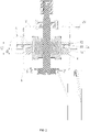
- the electric motor may include a first end cover 1, a second end cover 2, a fastener, a stator assembly 3a and a rotor assembly 4.
- the first end cover 1 and the second end cover 2 are fixedly connected through the fastener.
- the stator assembly 3a is arranged at an outer periphery of the rotor assembly 4. Both the stator assembly 3a and the rotor assembly 4 are arranged in a chamber enclosed by the first end cover 1 and the second end cover 2.
- first end cover 1 close to the second end cover 2 extends outwardly in a radial direction to form a first flange portion 11, and one end of the second end cover 2 close to the first end cover 1 extends outwardly in a radial direction to form a second flange portion 21a.
- the first flange portion 11 the second flange portion 21a are aligned with each other.
- the first end cover 1 is formed through stretching or injection molding, has relatively thin wall thickness and relatively low strength, and is therefore easy to be squeezed and deformed during assembly.
- a support installation portion 331 is provided between the first flange portion 11 and the second flange portion 21a.
- the arrangement of the support installation portion 331 has a supporting effect on the first flange portion 11 of the first end cover 1, which can prevent the first flange portion 11 from being pressed and deformed.
- the fastener can provide a fixed connection between the first flange portion 11, the support installation portion 331, and the second flange portion 21a, thereby achieving a fixed connection between the first end cover 1 and the second end cover 2.
- the fastener may be selected from screws, pins and the like.
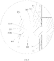
- an inner wall of the first end cover 1 has a first mating surface 12
- an outer periphery of the stator assembly 3a has a second mating surface 311, and the first mating surface 12 and the second mating surface 311 abut against each other, so that the first end cover 1 is wrapped around the outer circumference of the stator assembly 3a, thereby providing a supporting effect on the stator assembly 3a, which may indirectly strengthen the strength of the stator assembly 3a, and prevent the stator assembly 3a from vibrating to generate noise when the electric motor is working, thereby reducing the noise of the electric motor.
- an end surface of the first flange portion 11 facing the support installation portion 331 is a third mating surface 111
- a surface of the support installation portion 331 facing the first flange portion 11 is a fourth mating surface 3311.
- the third mating surface 111 and the fourth mating surface 3311 are contacted with each other, so as to realize supporting of the first flange portion 11 by the support installation portion 33.
- a distance between the end surface of the stator assembly 3a inside the first end cover 1 and the third mating surface 111 is HI, and a thickness of the stator assembly 3a is H2, where H1>2mm, H2 ⁇ 60mm.
- the stator assembly 3a is arranged to have an axial length of at least 2 mm being fitted with the first end cover 1, that is, a fitting length of the first mating surface 12 and the second mating surface 311 is at least 2 mm, so as to ensure a noise reduction effect of the first end cover 1 on the stator assembly 3a.
- H1 ⁇ H2 the stator assembly 3a is arranged to have a part being located in the first end cover 1 and a part being located in the second end cover 2, so that the first end cover 1 and the second end cover 2 both provide a wrapping effect on the stator assembly 3a.
- the stator assembly 3a includes a middle iron core 33, a first side iron core 31 and a second side iron core 32, and the first side iron core 31 and the second side iron core 32 are respectively provided on opposite sides of the middle iron core 33.
- the middle iron core 33, the first side iron core 31 and the second side iron core 32 are all formed by laminating a plurality of punching pieces.
- the middle iron core 33 radially extends to form the above-mentioned support installation portion 331, and the support installation portion 331 is sandwiched between the first flange portion 11 and the second flange portion 21a.
- the first flange portion 11 is supported by the middle iron core 33, thus a deformation of the first flange portion 11 can be prevented.
- a plurality of first flange portion 11 and a plurality of second flange portion 21a may be provided being distributed circumferentially on an outer periphery of the first end cover 1 and the second end cover 2 respectively. And accordingly, a plurality of support installation portions 331 is also provided.
- the first side iron core 31 is disposed in the first end cover 1, an outer periphery of the first side iron core 31 has the above-mentioned second mating surface 311, and the inner wall of the first end cover 1 has the first mating surface 12.
- the first mating surface 12 and the second mating surface 311 are both arc-shaped, and central axes of the first mating surface 12 and the second mating surface 311 coincide with each other, so that the first mating surface 12 and the second mating surface 311 are completely fitted.
- the first mating surface 12 and the second mating surface 311 are in an interference fit, so that the first end cover 1 has a supporting effect on the first side iron core 31.
- first mating surface 12 and the second mating surface 311 may be an annular surface composed of multiple spaced arc surfaces or may be an entire annular surface.
- specific structures of the first mating surface 12 and the second mating surface 311 are not limited.
- the first mating surface 12 and the second mating surface 311 may also be surfaces in the shape of a square, a waist circle, a polygon, or the like.
- the second side iron core 32 is located in the second end cover 2, an outer periphery of the second side iron core 32 has an arc-shaped fifth mating surface 321, and an inner side of the second end cover 2 has an arc-shaped sixth mating surface 24.
- Central axes of the fifth mating surface 321 and the sixth mating surface 24 coincide with each other, so that the fifth mating surface 321 and the sixth mating surface 24 are completely fitted.
- the fifth mating surface 321 and the sixth mating surface 24 are in an interference fit, so that the second end cover 2 has a supporting effect on the second side iron core 32.
- the fifth mating surface 321 and the sixth mating surface 24 may be annular surfaces composed of multiple spaced arc surfaces or may be an entire annular surface.
- the specific structures of the fifth mating surface 321 and the sixth mating surface 24 are not limited here.
- the fifth mating surface 321 and the sixth mating surface 24 may also be surfaces in the shape of a square, a waist circle, a polygon, or the like.
- the first flange portion 11 is provided with a first connection hole 110
- the support installation portion 331 is provided with a second connection hole 3310
- the second flange portion 21a is provided with a third connection hole 210
- the first connection hole 110, the second connection hole 3310, and the third connection hole 210 are arranged to be aligned with each other.
- the fastener is arranged to be extended into the first connection hole 110, the second connection hole 3310 and the third connection hole 210, so that the first end cover 1, the middle iron core 33 and the second end cover 2 are fixed to each other.
- the fastener may optionally be a screw, and the screw, passing through the first connection hole 110 and the second connection hole 3310, is threadedly connected to the third connection hole 210.
- the fastener may optionally be a pin, and the pin is configured to pass through the first connection hole 110, the second connection hole 3310 and the third connection hole 210.
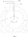
- a plurality of support installation portions 331 are provided, and the support installation portions 331 are circumferentially arranged on circumference of the middle iron core 33.
- three support installation portions 331 are provided, and correspondingly, three first flange portions 11 and three second flange portions 21a are also provided.
- one first flange portion 11 is provided having an annular shape
- one second flange portion 21a is provided having an annular shape.
- the three support installation portions 331 are circumferentially arranged on the circumference of the middle iron core 33.
- A1, A2, and A3 are equal, and each support installation portion 331 is evenly arranged on the circumference of the middle iron core 33 in a circumferential direction.
- a triangle formed by lines connecting the center points of the three second connection holes 3310 is a non-equilateral triangle, that is, the three third connection holes 3310 are not uniformly arranged on a stator blade in the circumferential direction.
- the incoming material is a material strip.
- at the same width position at least two stator blades can be punched out.
- the third connection hole 3310 is asymmetrically arranged, so that waste on the material belt can be fully utilized. It is possible to punch out the stator blade with the support installation portion 331 without widening the material strip, which can save material.
- A1 90 ⁇ 5°
- the maximum distance between an outer edge of the support installation portion 331 and the center of the stator assembly 3a is D1
- a distance between the center of the second connection hole 3310 and the center of the stator assembly 3a is D2.
- the line connecting the center point of the second connection hole 3310 and the center point of the stator assembly 3a extends to the outer edge of the support installation portion 331
- D1 is a distance from the intersection of the line and the outer edge of the support installation portion 331 to the center of the stator assembly 3a.
- 0.5 ⁇ D2/D1 ⁇ 1 a value of D2/D1 may be 0.6, 0.7, 0.8, 0.9, etc.
- the value of D2/D1 is in a range from 0.5 and 1.
- a side of the support installation portion 331 facing the second flange portion 21a has a first positioning portion, and the second flange portion 21a is correspondingly provided with a second positioning portion.
- the first positioning portion and the second positioning portion are plugged into each other, such that relative positions of the support installation portion 331 and the second flange portion 21a in the circumferential direction are fixed to prevent the stator assembly 3a from rotating.
- Outer contour shapes of the first positioning portion and the second positioning portion are matched.
- the first positioning portion may be a groove or a through hole
- the second positioning portion may be a convex rib, a convex column, etc.
- the second positioning portion may be a groove or a through hole
- the first positioning portion may be a convex rib, a convex column, etc.
- the first end cover 1 may be made of a metal material, a bulk molding material or a resin material.
- the first end cover 1 may be formed through stretching, and when the first end cover 1 is made of the bulk molding compound, the resin material, etc., the first end cover 1 may be formed through injection molding.
- the bulk molding compound can be referred to as a BMC plastic, and the BMC plastic is a thermosetting plastic, in which various inert fillers, fiber reinforcements, catalysts, stabilizers and pigments are mixed to form an adhesive "putty-like" composite material for compression molding or injection molding.
- an outer wall of the second end cover 2 is extended forming the first installation foot 23, and the first installation foot 23 is configured to form a fixed connection with external structures such as a water storage bucket.
- Part of the second flange portion 21a is integrally formed with the first installation foot 23, and the third connection hole 210 is defined in the first installation foot 23.
- the outer side of the second end cover 2 has a first installation foot 23 and also has a water baffle 22.
- the first installation foot 23 and the water baffle 22 are both connected to the outer wall of the second end cover 2.
- the water baffle 22 is also connected to a side wall of the first installation foot 23, so that the water baffle 22, the outer wall of the second end cover 2 and the first installation foot 23 form a triangular-like structure, so that the arrangement of the water baffle 22 and the first installation foot 23 can be more stable.
- a function of the first installation foot 23 is to be fixedly connected with external structures such as a water storage bucket.
- the first installation foot 23 may be provided with other structures such as installation holes to facilitate connection with the external structures.
- the water baffle 22 is provided with a terminal box installation portion 220 for mounting a terminal box.
- the terminal box installation portion 220 may optionally be a structure of a through hole or a groove.
- the second embodiment differs from the first embodiment in that: the support installation portion is integrally formed with the first flange portion or the second flange portion. That is, the support installation portion is formed by extending the second flange portion 21a in the first embodiment toward the first flange portion 11, forming the support installation portion (the second flange portion 21b) in the second embodiment, i.e., the support installation portion is integrally formed with the second flange portion 21b, while supporting the first flange portion 11.
- the support installation portion is formed by extending the first flange portion 11 in the first embodiment toward the second flange portion 21a, forming the support installation portion in the second embodiment, i.e., the support installation portion is integrally formed with the first flange portion 11.
- the middle iron core of the stator assembly 3b does not require radial extension.
- the second end cover 2 is provided with an outlet port 25 for connecting with a controller or a washing machine.
- the outlet port 25 is disposed on the second end cover 2, the strength of the second end cover 2 will not be reduced.
- the strength of the outlet port 25 may be affected as the first end cover 1 is thinner.
- the third embodiment differs from the second embodiment in that: the support installation portion 6 is formed separately from the first flange portion 11 and the second flange portion 21a, so that the support installation portion 6 may be a support sleeve or a block, which is disposed between the first flange portion 11 and the second flange portion 21a.
- the support sleeve or the block is provided with a second connection hole 3310 for the fastener to pass through. Even if the support installation portion 6 is configured to be a support sleeve or a block, the effect of supporting the first flange portion 11 can also be achieved.
- a side of a support block 6 facing the second flange portion 21 has a first positioning portion, and the second flange portion 21a is correspondingly provided with a second positioning portion.
- the first positioning portion and the second positioning portion are plugged into each other, such that relative positions of the support block 6 and the second flange portion 21a in the circumferential direction are fixed to prevent the stator assembly 3 from rotating.
- the outer contour shapes of the first positioning portion and the second positioning portion are matched.
- the first positioning portion may be a groove or a through hole
- the second positioning portion may be a convex rib, a convex column, etc.
- the second positioning portion may be a groove or a through hole
- the first positioning portion may be a convex rib, a convex column, etc.
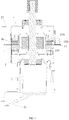
- the fourth embodiment differs from the first embodiment in that: the electric motor also includes a controller and a controller cover 5.
- the controller cover 5 is fixed on the first end cover 1.
- the controller is disposed inside the controller cover 5.
- the controller may be fixed on the first end cover 1, fixed on the controller cover 5 or pressed by the controller cover 5 on the first end cover 1.
- An outer side of the controller cover 5 is provided with a second installation foot 51, in this way, it may not be necessary to provide a mounting structure on the first end cover 1, when an electric motor is fixed to an external structure such as a water storage bucket, so that the structure of the first end cover 1 is simplified by using processes such as stretching and injection molding.
- the second installation foot 51 are transferred and arranged on the controller cover 5, so that not only the controller and the electric motor can form an integrated structure, but also the structure of the first end cover 1 can be simplified, saving the cost of the first end cover 1.
- the first installation foot 23 and the second installation foot 51 are jointly mounted on the external structure, so that an installation of the electric motor is more stable.
- the first installation foot 23 and the second installation foot 51 may be provided with installation holes for mounting connection components such as screws.
- a surface of the controller cover 5 is provided with heat dissipation ribs to enhance heat dissipation of the controller cover 5.
- controller cover 5 and the second installation foot 51 are separately formed or integrally formed.
- the controller cover 5 may be injection-molded from a bulk molding material, a resin material, or the like.
- the second installation foot 51 may be made of an aluminum alloy, a bulk molding material, a resin material and other materials.
- the present application also provides a washing machine, including the electric motor in any of the above embodiments.
- the electric motor includes a first end cover 1, a second end cover 2, a fastener for connecting the first end cover 1 and the second end cover 2, a stator assembly and a rotor assembly 4.
- the first end cover 1 is formed by stretching or injection molding, having a thinner wall thickness and lower strength.
- the first end cover 1 is provided with a first flange portion 11 configured for connecting the fastener
- the second end cover 2 is provided with a second flange configured for connecting the fastener.
- the stator assembly can be wrapped, which strengthens the strength of the stator assembly, and reduces the noise of the stator assembly during operation of the electric motor.
- the washing machine also includes a water storage bucket, and the electric motor is fixed on the water storage bucket through the above-mentioned first installation foot 23 and second installation foot 51.
Landscapes
- Engineering & Computer Science (AREA)
- Power Engineering (AREA)
- Textile Engineering (AREA)
- Motor Or Generator Frames (AREA)
- Main Body Construction Of Washing Machines And Laundry Dryers (AREA)
- Iron Core Of Rotating Electric Machines (AREA)
Applications Claiming Priority (4)
| Application Number | Priority Date | Filing Date | Title |
|---|---|---|---|
| CN202022024611.3U CN212935628U (zh) | 2020-09-15 | 2020-09-15 | 电动机及洗衣机 |
| CN202022023467.1U CN212751976U (zh) | 2020-09-15 | 2020-09-15 | 电动机及洗衣机 |
| CN202010969965.7A CN114189084A (zh) | 2020-09-15 | 2020-09-15 | 电动机及洗衣机 |
| PCT/CN2020/137616 WO2022057129A1 (zh) | 2020-09-15 | 2020-12-18 | 电动机及洗衣机 |
Publications (2)
| Publication Number | Publication Date |
|---|---|
| EP4007129A1 true EP4007129A1 (de) | 2022-06-01 |
| EP4007129A4 EP4007129A4 (de) | 2022-12-07 |
Family
ID=80775715
Family Applications (1)
| Application Number | Title | Priority Date | Filing Date |
|---|---|---|---|
| EP20950481.0A Pending EP4007129A4 (de) | 2020-09-15 | 2020-12-18 | Elektromotor und waschmaschine |
Country Status (5)
| Country | Link |
|---|---|
| US (1) | US12132374B2 (de) |
| EP (1) | EP4007129A4 (de) |
| JP (1) | JP7455959B2 (de) |
| KR (1) | KR102657432B1 (de) |
| WO (1) | WO2022057129A1 (de) |
Families Citing this family (1)
| Publication number | Priority date | Publication date | Assignee | Title |
|---|---|---|---|---|
| KR102728918B1 (ko) * | 2023-03-16 | 2024-11-13 | 뉴모텍(주) | 청소기용 모터 |
Family Cites Families (57)
| Publication number | Priority date | Publication date | Assignee | Title |
|---|---|---|---|---|
| DE608371C (de) * | 1931-06-24 | 1935-01-24 | Aeg | Klammer zum Zusammenhalten des Staenderblechpaketes von elektrischen Maschinen |
| DE2148827A1 (de) * | 1971-09-30 | 1973-04-12 | Siemens Ag | Elektromotor mit zwei sein staenderblechpaket uebergreifenden lagerschilden bzw. gehaeusehaelften |
| JPS60202116A (ja) | 1984-03-28 | 1985-10-12 | Toho Rayon Co Ltd | エポキシ樹脂組成物 |
| JPS62177253U (de) * | 1985-12-25 | 1987-11-11 | ||
| US4668898A (en) | 1986-04-21 | 1987-05-26 | General Electric Company | Electronically commutated motor |
| JPH01321848A (ja) * | 1988-06-21 | 1989-12-27 | Sanyo Electric Co Ltd | 回転電機 |
| EP1110802A3 (de) * | 1992-05-12 | 2001-07-11 | Seiko Epson Corporation | Elektrofahrzeug |
| DE9301825U1 (de) * | 1993-02-10 | 1994-06-16 | Robert Bosch Gmbh, 70469 Stuttgart | Elektrische Maschine, insbesondere Drehstromgenerator für Brennkraftmaschinen |
| JPH07212993A (ja) | 1994-01-18 | 1995-08-11 | Matsushita Electric Ind Co Ltd | モータのステータコア |
| JPH08223846A (ja) | 1995-02-20 | 1996-08-30 | Fujitsu General Ltd | 電動機 |
| JPH08266001A (ja) * | 1995-03-20 | 1996-10-11 | Fujitsu General Ltd | 電動機 |
| DE19532506B4 (de) * | 1995-09-02 | 2016-05-25 | Robert Bosch Gmbh | Elektrische Maschine |
| EP1416611B1 (de) * | 1999-12-14 | 2005-04-27 | Mitsubishi Denki Kabushiki Kaisha | Drehstromgenerator |
| JP2001251806A (ja) | 2000-03-01 | 2001-09-14 | Hitachi Ltd | 車両用交流発電機 |
| TW525871U (en) * | 2001-11-06 | 2003-03-21 | Lidashi Industry Co Ltd | Improved structure of motor housing |
| JP2005304213A (ja) | 2004-04-14 | 2005-10-27 | Toyota Motor Corp | ステータ固定構造 |
| JP4583191B2 (ja) | 2005-01-28 | 2010-11-17 | 三菱電機株式会社 | 回転電機 |
| JP4811114B2 (ja) | 2006-05-15 | 2011-11-09 | トヨタ自動車株式会社 | ステータの固定構造および車両 |
| US8269380B2 (en) | 2006-06-01 | 2012-09-18 | Panasonic Corporation | Brushless motor for washing machine having stress reduction on sensor casing and washing machine having the brushless motor mounted therein |
| ITMI20070304U1 (it) * | 2007-09-11 | 2009-03-12 | Askoll Holding Srl | Supporto per il fissaggio di un motore elettrico ad una vasca di una lavatrice o simile elettrodomestico |
| KR101460133B1 (ko) * | 2009-08-17 | 2014-11-11 | 삼성전자 주식회사 | 세탁기용 모터와 이를 가지는 세탁기 |
| JP2011155738A (ja) | 2010-01-26 | 2011-08-11 | Toyota Motor Corp | ステータ |
| KR101707402B1 (ko) * | 2010-04-09 | 2017-02-16 | 삼성전자주식회사 | 세탁기용 모터와 이를 갖는 세탁기 |
| US9093884B2 (en) | 2010-10-20 | 2015-07-28 | Nidec Motor Corporation | Integrated motor and control |
| DE102010062824A1 (de) | 2010-12-10 | 2012-06-14 | BSH Bosch und Siemens Hausgeräte GmbH | Gehäuseloser Elektromotor für ein Haushaltsgerät |
| DE102010062822A1 (de) * | 2010-12-10 | 2012-06-14 | BSH Bosch und Siemens Hausgeräte GmbH | Gehäuseloser Elektromotor für ein Haushaltsgerät |
| JP5485926B2 (ja) * | 2011-02-25 | 2014-05-07 | 東芝産業機器製造株式会社 | 固定子鉄心の製造方法 |
| JP5898876B2 (ja) | 2011-07-26 | 2016-04-06 | 山洋電気株式会社 | 電気機器 |
| JP5742570B2 (ja) | 2011-08-09 | 2015-07-01 | トヨタ自動車株式会社 | 電動車両の駆動装置 |
| KR20130063212A (ko) | 2011-12-06 | 2013-06-14 | 삼성전기주식회사 | 아웃터 로터 타입의 모터 |
| CN202721533U (zh) | 2012-06-29 | 2013-02-06 | 中山大洋电机股份有限公司 | 一种新型端盖及其应用的外转子电机 |
| JP5660400B2 (ja) | 2012-08-03 | 2015-01-28 | 株式会社デンソー | 回転電機、および、これを用いた電動パワーステアリング装置 |
| CN102801253A (zh) | 2012-08-20 | 2012-11-28 | 常州新亚电机有限公司 | 一种电机与控制器组件 |
| CN203660711U (zh) * | 2013-12-09 | 2014-06-18 | 中山大洋电机制造有限公司 | 一种拉伸端盖电机 |
| CN203883586U (zh) | 2014-05-28 | 2014-10-15 | 中山大洋电机股份有限公司 | 一种电机 |
| CN203933222U (zh) | 2014-07-16 | 2014-11-05 | 浙江伟康电机有限公司 | 用于滚筒洗衣机串激电机的拉伸铁端盖结构 |
| CN104158333B (zh) | 2014-07-29 | 2017-11-24 | 佛山市威灵洗涤电机制造有限公司 | 电机端盖以及具有其的一体式电机和分体式电机 |
| US20160056681A1 (en) * | 2014-08-21 | 2016-02-25 | Nidec Motor Corporation | Integrated motor and controller with internal heat sink and snap-on dripshield |
| CN104682607A (zh) | 2015-03-10 | 2015-06-03 | 佛山市威灵洗涤电机制造有限公司 | 电机后端盖、集成式电机及洗衣机 |
| CN204794453U (zh) * | 2015-05-21 | 2015-11-18 | 中山大洋电机制造有限公司 | 一种拉伸端盖电机 |
| CN204733005U (zh) * | 2015-06-30 | 2015-10-28 | 中山大洋电机股份有限公司 | 一种铁壳电机 |
| CN204794462U (zh) * | 2015-07-06 | 2015-11-18 | 黄炜琦 | 一种拉伸端盖电机 |
| CN205039640U (zh) | 2015-10-14 | 2016-02-17 | 苏州三星电子有限公司 | 一种滚筒洗衣机、电机及其组合式后端盖 |
| CN105386278B (zh) * | 2015-11-26 | 2018-01-16 | 佛山市威灵洗涤电机制造有限公司 | 家用电器的电机安装结构 |
| CN106253572A (zh) | 2016-07-28 | 2016-12-21 | 佛山市威灵洗涤电机制造有限公司 | 家用电器 |
| CN206962600U (zh) * | 2017-07-26 | 2018-02-02 | 佛山市威灵洗涤电机制造有限公司 | 电机和滚筒洗衣机 |
| CN107313948B (zh) * | 2017-07-31 | 2023-07-18 | 广东威灵电机制造有限公司 | 电机泵和洗碗机 |
| CN109962541A (zh) * | 2017-12-26 | 2019-07-02 | 上海海立电器有限公司 | 电机定子、压缩机以及压缩机的制造方法 |
| CN108551223B (zh) | 2018-06-14 | 2024-10-22 | 广东威灵电机制造有限公司 | 用于电机的端盖和具有其的电机、洗衣机 |
| CN110768474B (zh) | 2018-07-27 | 2025-07-25 | 广东威灵电机制造有限公司 | 电机和具有其的洗衣机 |
| CN208489737U (zh) | 2018-08-20 | 2019-02-12 | 广东威灵电机制造有限公司 | 用于电机的端盖、电机和洗衣机 |
| WO2020071739A1 (en) | 2018-10-02 | 2020-04-09 | Samsung Electronics Co., Ltd. | Washing machine |
| JP2020054628A (ja) | 2018-10-02 | 2020-04-09 | 三星電子株式会社Samsung Electronics Co.,Ltd. | 洗濯機 |
| CN210273657U (zh) | 2019-08-01 | 2020-04-07 | 莱克电气股份有限公司 | 一种电机与电机控制器一体化安装机构 |
| CN212343506U (zh) | 2020-09-15 | 2021-01-12 | 佛山市威灵洗涤电机制造有限公司 | 电动机及洗衣机 |
| CN212751976U (zh) | 2020-09-15 | 2021-03-19 | 佛山市威灵洗涤电机制造有限公司 | 电动机及洗衣机 |
| CN212935583U (zh) * | 2020-09-15 | 2021-04-09 | 佛山市威灵洗涤电机制造有限公司 | 定子铁芯冲片、定子铁芯及电动机 |
-
2020
- 2020-12-18 WO PCT/CN2020/137616 patent/WO2022057129A1/zh not_active Ceased
- 2020-12-18 KR KR1020227006919A patent/KR102657432B1/ko active Active
- 2020-12-18 JP JP2022513594A patent/JP7455959B2/ja active Active
- 2020-12-18 EP EP20950481.0A patent/EP4007129A4/de active Pending
-
2022
- 2022-02-28 US US17/682,500 patent/US12132374B2/en active Active
Also Published As
| Publication number | Publication date |
|---|---|
| KR20220042196A (ko) | 2022-04-04 |
| JP2022553118A (ja) | 2022-12-22 |
| WO2022057129A1 (zh) | 2022-03-24 |
| KR102657432B1 (ko) | 2024-04-16 |
| US12132374B2 (en) | 2024-10-29 |
| EP4007129A4 (de) | 2022-12-07 |
| US20220181944A1 (en) | 2022-06-09 |
| JP7455959B2 (ja) | 2024-03-26 |
Similar Documents
| Publication | Publication Date | Title |
|---|---|---|
| EP3770429B1 (de) | Elektrische ölpumpe | |
| CN112392762B (zh) | 扇轮 | |
| CN212751976U (zh) | 电动机及洗衣机 | |
| CN101355190B (zh) | 电波接收用变频器和卫星广播接收用天线装置 | |
| US20220181944A1 (en) | Electric motor and washing machine | |
| US12034340B2 (en) | Motor external rotor, brushless permanent magnet motor and electrical product | |
| KR102589674B1 (ko) | 로터 및 이를 포함하는 모터 | |
| US12136852B2 (en) | Electromotor and laundry machine | |
| CN212935583U (zh) | 定子铁芯冲片、定子铁芯及电动机 | |
| KR20200006850A (ko) | 모터 | |
| KR101757542B1 (ko) | 차량용 전기 모터 | |
| CN206349826U (zh) | 一种永磁同步电机 | |
| US20150322963A1 (en) | Casing and blower | |
| CN107017716B (zh) | 转子冲片、转子、电机及转子冲片加工方法 | |
| CN215498529U (zh) | 一种电机壳体结构及电机 | |
| CN211127347U (zh) | 电机转子 | |
| US8651818B2 (en) | Locking device | |
| CN109494915B (zh) | 一种可带驱动回路的电机端盖及电机 | |
| CN114172301B (zh) | 电动机及洗衣机 | |
| CN107240977B (zh) | 电机后端盖及电机 | |
| CN207218466U (zh) | 磁感应元件、马达以及包含该马达的车载产品 | |
| US12486847B2 (en) | Electric pump | |
| CN219012917U (zh) | 风扇 | |
| CN211791029U (zh) | 一种简便安装的电机外壳以及具有该外壳的电机 | |
| CN211266602U (zh) | 电机 |
Legal Events
| Date | Code | Title | Description |
|---|---|---|---|
| STAA | Information on the status of an ep patent application or granted ep patent |
Free format text: STATUS: UNKNOWN |
|
| STAA | Information on the status of an ep patent application or granted ep patent |
Free format text: STATUS: THE INTERNATIONAL PUBLICATION HAS BEEN MADE |
|
| PUAI | Public reference made under article 153(3) epc to a published international application that has entered the european phase |
Free format text: ORIGINAL CODE: 0009012 |
|
| STAA | Information on the status of an ep patent application or granted ep patent |
Free format text: STATUS: REQUEST FOR EXAMINATION WAS MADE |
|
| 17P | Request for examination filed |
Effective date: 20220228 |
|
| AK | Designated contracting states |
Kind code of ref document: A1 Designated state(s): AL AT BE BG CH CY CZ DE DK EE ES FI FR GB GR HR HU IE IS IT LI LT LU LV MC MK MT NL NO PL PT RO RS SE SI SK SM TR |
|
| REG | Reference to a national code |
Ref country code: DE Ref legal event code: R079 Free format text: PREVIOUS MAIN CLASS: H02K0005040000 Ipc: H02K0001180000 |
|
| A4 | Supplementary search report drawn up and despatched |
Effective date: 20221104 |
|
| RIC1 | Information provided on ipc code assigned before grant |
Ipc: D06F 37/30 20200101ALN20221028BHEP Ipc: H02K 5/24 20060101ALN20221028BHEP Ipc: H02K 5/04 20060101ALN20221028BHEP Ipc: H02K 5/08 20060101ALN20221028BHEP Ipc: H02K 5/15 20060101ALI20221028BHEP Ipc: H02K 1/18 20060101AFI20221028BHEP |
|
| DAV | Request for validation of the european patent (deleted) | ||
| DAX | Request for extension of the european patent (deleted) | ||
| STAA | Information on the status of an ep patent application or granted ep patent |
Free format text: STATUS: EXAMINATION IS IN PROGRESS |
|
| 17Q | First examination report despatched |
Effective date: 20250130 |